

Page 1
TLF200/TLR200 POTS CODEC
Operation Manual
For Software Version 2.205
Page 2

COMMANDER WELCOME
©Tieline Technology - 2 - August 2002
TLF200
TLR200
COMMANDER Features
¾ Two balanced Microphone/Line inputs; Standard XLR three-pin female.
¾ Optional ISDN Interface.
¾ Choice of a Compact Field unit or a Studio (rack mount) unit.
¾ LED Peak Program level meter (–12dBu to +16dBu).
¾
A cell phone jack (3.5mm) is provided for standard bi-directional phone quality audio.
¾ Two CMOS relay facilities are provided via 3.5mm jacks for remote control of
equipment.
¾
Optional Data Streaming for data link applications.
The COMMANDER has the same software upgrade capabilities as all other Tieline
Codecs. Full upgrades are possible using the Tieline Toolbox software.
We are continually updating our manuals and software…Get the latest at;
www.tieline.com.
IMPORTANT!
Register on our website as a Tieline user and get notification of new software
Page 3

COMMANDER WARRANTY
WARRANTY
WARRANTY
TIELINE TECHNOLOGY (Manufacturer) warrants that this product is free of defects in both
materials and workmanship.
Should any part of this equipment be defective, the Manufacturer agrees, at its option, to:
a) Repair or replace any defective part free of charge (except transportation charges) for a
period of one year from the date of the original purchase, provided the owner returns
the equipment to the Manufacturer. No charge will be made for parts or labor during this
period or
b) Furnish replacement for any defective parts in the equipment for a period of one year
from the date of original purchase. Replacement parts shall be furnished without
charge, except labor and transportation.
This Warranty excludes assembled products not manufactured by the Manufacturer
whether or not they are incorporated in a Manufacturer product or sold under a
Manufacturer part or model number.
THE WARRANTY IS TERMINATED WHEN ANY OF THE FOLLOWING HAS
OCCURRED TO THE EQUIPMENT:
a) Damage by negligence, accident, act of God, mishandling, or it has been operated
incorrectly to the various instructions described in the Operation Manual.
b) Altered or repaired by other than the Manufacturer or an authorized service
representative of the Manufacturer.
c) Any adaptations or accessories other than those manufactured or provided by the
Manufacturer have been made or attached to the equipment, which, in the determination of
the Manufacturer, shall have affected the performance, safety or reliability of the
equipment.
d) The original serial number has been modified or removed.
NO OTHER WARRANTY, EXPRESS OR IMPLIED, INCLUDING WARRANTY OF
MERCHANTABILITY OR FITNESS FOR ANY PARTICULAR USE, APPLIES TO THE
EQUIPMENT, nor is any person or company authorized to assume any warranty for the
Manufacturer or any other liability in connection with the sale of the Manufacturer's
products.
Manufacturer does not assume any responsibility for consequential damages, expenses, or
loss of revenue or property, inconvenience, or interruption in operation experienced by the
customer due to a malfunction in the purchased equipment.
No warranty service performed on any product shall extend the applicable warranty period.
In case of unsatisfactory operation, the purchaser shall promptly notify the Manufacturer in
writing, giving full particulars as to the defects or unsatisfactory operation. Upon receipt of
such notice, the Manufacturer will give instructions respecting the shipment of the
equipment, or such other matters as it elects to honor this warranty as above provided.
This warranty does not cover damage to the equipment during shipping and the
Manufacturer assumes no responsibility for such damage. The customer shall pay all
shipping costs.
This warranty extends only to the original purchaser and is not assignable or transferable.
Subject to change without notice
Page 4

COMMANDER TABLE OF CONTENTS
Table of Contents
WARRANTY ..........................................................................................................3
INSTALLATION AND USAGE TIPS ......................................................................7
CONTROLS & CONNECTIONS............................................................................8
Field Unit TLF200 ............................................................................................................................. 8
Rack Unit TLR200 ............................................................................................................................ 9
QUICK START GUIDE for the Beginner..............................................................10
Operating the Menu Selector (MS)................................................................................................. 10
Setup for Microphone Input ............................................................................................................ 10
GETTING STARTED...........................................................................................12
Setting Factory Defaults ................................................................................................................. 12
Dialing a number............................................................................................................................. 13
Dialing From an Office or Hotel Room............................................................................................13
Handset Dialing .............................................................................................................................. 14
Memory Dialing from Interstate or International call areas............................................................. 14
How to store a phone number ........................................................................................................ 15
FUNCTION KEYS................................................................................................17
Quick Function Tips ........................................................................................................................ 17
Default Function Keys..................................................................................................................... 17
Function Key Options ..................................................................................................................... 18
DETAILED CONFIGURATION ............................................................................20
Setup Menu .................................................................................................................................... 20
Sub Menus of 01 – View Configuration .......................................................................................... 22
Sub Menus of 02 – Codec Setup.................................................................................................... 26
Sub Menus of 03 – Modem setup...................................................................................................27
Sub Menus of 04 – Dialing setup.................................................................................................... 28
Sub Menus of 05 – Unit Setup........................................................................................................ 29
Sub Menus of 06 – ISDN Setup ..................................................................................................... 30
Sub Menus of 07 – Advanced Setup .............................................................................................. 31
Sub Menus of 08 – Timer Functions...............................................................................................32
Sub Menus of 09 – Reset Functions .............................................................................................. 33
Sub Menus of 10 – Test Modes...................................................................................................... 33
Sub Menus of 11 – Memory Setup ................................................................................................. 33
Sub Menus of 12 – Unit Details ...................................................................................................... 33
HOW THE COMMANDER WORKS.....................................................................34
Theory of Operation........................................................................................................................ 34
Peak Level Meter............................................................................................................................ 34
Modem Negotiation and Line Quality ............................................................................................. 35
Master Slave Operation.................................................................................................................. 35
ISDN Operation .............................................................................................................................. 36
Relay Control .................................................................................................................................. 36
Page 5

COMMANDER WELCOME
©Tieline Technology - 5 - August 2002
TOOLBOX Software ............................................................................................38
Preparing to use the ToolBox application....................................................................................... 38
Connecting COMMANDER to the PC ............................................................................................ 38
Menu Items ..................................................................................................................................... 39
General Configuration..................................................................................................................... 41
POTS Setup.................................................................................................................................... 41
Local Control................................................................................................................................... 42
Remote Control............................................................................................................................... 43
Line Monitor .................................................................................................................................... 43
Chat ................................................................................................................................................ 44
Phone Book .................................................................................................................................... 45
Functions ........................................................................................................................................ 46
Software Upgrade........................................................................................................................... 47
Mic / Line Audio In Connector ........................................................................................................ 48
Program Out Connector ................................................................................................................. 48
RS 232 Interface Connector ........................................................................................................... 48
TIELINE CODEC SOLUTIONS FAMILY..............................................................49
COMPLIANCES...................................................................................................50
INDEX..................................................................................................................52
Page 6

COMMANDER INTRODUCTION
INTRODUCTION
Thank you for buying a Tieline technology codec!
In the audio codec broadcast revolution Hearing is believing….
Tieline, providers of the world’s best Plain Old Telephone Service (POTS) Codec
technology, developed the COMMANDER codec to provide high quality, bi-directional
audio for POTS together or ISDN operation.
Tieline has changed the opinions of even the most critical broadcasters, proving that
stable high bandwidth links with unfailing audio and data is the new reality for
broadcasting over a telephone line.
A superb DSP algorithm delivers crystal clear 15kHz bi-directional audio in real time at bit
rates as low as 24kbps with a small 100ms delay and a minimal loss of quality over a
standard telephone line.
COMMANDER is the versatile CODEC solution, giving you full broadcast freedom with
the ability to use ISDN if required. COMMANDER is part of the Audio Codec Family that
includes the PATRIOT – the economical solution and i-Mix – the Sportscasters Dream
Machine.
COMMANDER provides audio-link opportunities previously that were impossible or
simply too expensive to use. Broadcast journalists and presenters now have an easy to
use compact portable field codec with high quality, two-way audio link performance.
COMMANDER can be transported as carry-on baggage allowing convenient worldwide
coverage with minimal equipment or is available as a professional Studio rack mount
unit.
Using the COMMANDER is as simple as plugging it into a POTS (Plain Old Telephone
Service) or ISDN (optional extra) phone line and dialing the destination number. The
receiving Tieline codec automatically answers the call and establishes the link. For POTS
connections, a built-in modem negotiates the best possible data rate for high-quality lownoise and distortion, bi-directional audio.
COMMANDER features include:
• High quality audio at very low bit rates
• ISDN as an optional extra
• Many remote control features for remote operation
• Purpose built modem for POTS codec operation
• Automatic link re-connect in the event of line dropouts
• Extensive menu system caters for most individual applications
• Choice of optional extras such as;
o 15kHz audio in one direction and up to 9600bps in the opposite direction
OR
o 7kHz audio and up to 4800bps of data simultaneously in both directions
• Fast and easy configuration via a Windows 9*/ME/2K software application:
Toolbox
Page 7

COMMANDER INSTALLATION AND USAGE TIPS
INSTALLATION AND USAGE TIPS
While the TIELINE COMMANDER is a very reliable telecom product, its performance will only be
as good as the line that it is operating over.
Proper precautions MUST be taken to ensure that only the COMMANDER uses the line.
Remove these possible interference sources:
• Other telephone handsets
• Fax machines
• Computer modems
• Alarm systems
• Extension bells
• Line monitoring devices
Important precaution for the COMMANDER phone-line:
ENSURE THAT CALL WAITING IS DISABLED!
It is always preferable to obtain a dedicated phone line from the local Exchange or Central Office.
Try to avoid going through a PBX, PABX, Key station or any other local exchange. If this is
unavoidable, check that the line works BEFORE you try to do a live program. Some of these
systems have poor line characteristics and may make the operation of the COMMANDER
marginal, if not unusable.
WARNING - DO NOT CONNECT YOUR TIELINE TO A DIGITAL PHONE SYSTEM AS
PERMANENT DAMAGE MAY OCCUR.
If you are unfamiliar with a particular facility, check that the line you are given is NOT a digital
line. This is very important. because If the unit becomes faulty due to the use of a digital phone
system, the Warranty automatically becomes void.
On most good lines, the COMMANDER is normally able to achieve 28,800 bps (Bits Per Second)
at a line quality of approximately 70%. If you are not able to achieve this level of operation, you
may have transmission problems with your line or the line at the other end of the connection.
CHECK:
• Length of the line from your site to the local Exchange or Central Office
• Presence of stub or party lines on your local loop
• Earth leakage problem on the line
• Equipment problem at the Exchange or CO
It is very desirable to have a local loop (The line from your office or home to the local CO or
Exchange) as short as possible. Optimum performance can be expected for lines up to about
three kilometers in length.
In some countries, it has been the practice to have more than one phone service attached to one
line. As more lines have been installed, the services have been separated but the unused lines
have remained connected to the local loop. Even though the old line may be unused, if it is still
present across your local loop, it will cause problems with your equipment operation.
A good line should have an earth isolation of better than ten meg-ohms. If your line is located in
an area where water is a problem, check out the earth leakage.
Although there are many factors at the Telco end that can cause problems, a problem that does
occasionally occur is if the clock on the interface codec to your line is not synchronized to the
network. A drifting clock will cause instability and unreliable COMMANDER performance. If you
suspect that this could be the problem, contact your local Telco.
Page 8
COMMANDER CONTROLS & CONNECTIONS
CONTROLS & CONNECTIONS
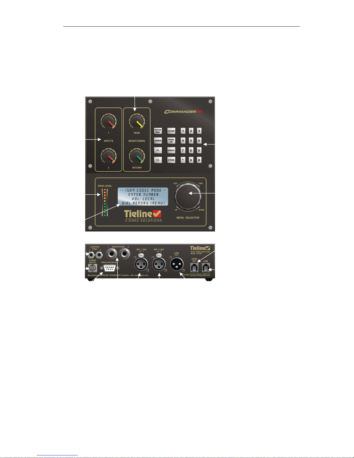
Field Unit TLF200
Menu Selector:
Rotate to scan Items
Click down to select item.
Visual
Output
LCD
Serial data
port for
connection to
a computer
and data
transmission
Keypad for Data Entry.
Function Keys,CLR
Hang Up etc.
Power
Supply
Software
controlled audio
input pots.
Software controlled send &
r
etu
rn
audio adjustme
nt POT
S
Headphone
monitoring
Balanced
mic/line
input 1
Balanced output
External Phone
Telephone Line
Peak
Program
Meter
Balanced
mic/line
input 2
2 CMOS relay
ports with
local or
remote control
operation
Page 9

COMMANDER CONTROLS & CONNECTIONS
Rack Unit TLR200
Headphone
monitoring
Menu Selector:
Rotate to scan Items
Click down to select
item.
Visual
Output
LCD
Keypad for Data Entry.
Function Keys,CLR
Hang Up etc.
Software
controlled audio
input pots
Software
controlled
send &
return audio
adjustment
POTS
ISDN Line
(Optional)
Balanced
output
External Phone
Telephone Line
Peak
Program
Meter
Relay Control
Interface
(
Optional
)
Balanced
mic/line
input 1
Serial data port for
connection to a
computer and data
transmission
Balanced
mic/line
input 2
Ancillary
Control
Ports
Page 10

COMMANDER QUICK START GUIDE for the Beginner
©Tieline Technology - 10 - August 2002
QUICK START GUIDE for the Beginner
Plug the COMMANDER in and wait for about 20 seconds for the unit to start up and load
the operating software.
Operating the Menu Selector (MS)
The rotary Menu Selector (MS) (see Controls & Connections on page 8) is used to operate
and configure the COMMANDER.
• Rotate the MS to scroll up, down or sideways on lists. The lists are viewable on the
LCD screen.
• Click the MS downwards to select an item in the LCD Screen which is highlighted in
[brackets].
NOTE the Keypad key marked CLEAR takes you back to the previous screen!
Setup for Microphone Input
Here is an example of how to use the MS in conjunction with the LCD screen to set up for a
microphone input;
1. Attach your Audio inputs to the XLR connector.
2. Attach a standard phone cord to RJ11 connector on the rear of your codec.
3. Use the MENU selector to change the Input to Microphone as follows;
Main screen – appears after start up
Select a Menu item by rotating the MS.
The selected item is identified by a square
bracket: [ ]. In this case you have a
choice of DIAL, MEMORY or MENU.
Choose MENU.
Scroll Down and select 05 Unit Setup.
Continues on next page…
Setup Menu
[05 Unit Setup ]
06 isdn Setuo
07 Advanced Setup
– POTS MODE –
Enter Number:
Ctl : Local
[DIAL] MEMORY MENU
– POTS MODE –
Enter Number:
Ctl : Local
[DIAL] MEMORY MENU
Page 11

COMMANDER QUICK START GUIDE for the Beginner
©Tieline Technology - 11 - August 2002
…Continues from previous page
Select 01 Set Input Gain.
On Input 1 Scroll to High Gain Mic and
Select.
Repeat for Input 2.
You can select Continue or Exit.
You have now changed the Input type.
4. Set Input 1 and 2 knobs to 2 ‘o’clock position. This sets the outgoing program level.
5. To hear outgoing
audio through the headphones (plug into rear socket) set the Send
knob to 3 ‘o’ clock and Return knob to minimum. To hear return
audio from the other
end - reverse the Send and Receive knob settings.
6. You are now SET to GO!
7. Repeat steps 2,4 & 6 for the “Destination” Tieline Codec equipment.
8. You can monitor the output using headphones attached to this COMMANDER.
Alternatively, connect the audio program output as desired on the destination
COMMANDER.
Note: the Return knob on the destination equipment is the headphone volume. It
does not adjust the program output level.
9. Using the keypad, enter the telephone number of the destination codec and press the
Enter/Dial key.
Important: Ensure you have installed your unit correctly as instructed in the Installation
and Usage Tips section on page 7.
Unit Setup
[01 Set Input Gain ]
02 PPM Mode
03 Relay Operation
Set Input Gain
INP1 : [ Line Level ]
INP2 : Line Level
Changes Saved…..
Continue Setup?
[CONTINUE] EXIT
Page 12

COMMANDER GETTING STARTED
©Tieline Technology - 12 - August 2002
GETTING STARTED
Setting Factory Defaults
Restoring to factory default settings is good practice. It gives your COMMANDER a configuration
with a predictable set of options.
FROM THE STARTUP SCREEN HERE’S HOW:
Rotate MS to
select MENU then Click MS.
Scroll using MS to [09 Reset Functions]
Select [09 Reset Functions] Click MS.
Scroll using MS
to [02 Reset Settings]
Select [02 Reset Settings] by clicking MS.
Continued on next page…
Setup Menu
[01 View Config ]
02 Codec Setup
03 Modem Setup
Setup Menu
[09 Reset Functions]
10 Test Modes
11 Memory Setup
Reset Functions
[01 Reset DSP ]
02 Reset Settings
03 Reset Phone Mem
Reset Functions
[02 Reset Settings ]
03 Reset Phone Mem
04 reset Funct Mem
– POTS MODE –
Enter Number:
Ctl : Local
[DIAL] MEMORY MENU
– POTS MODE –
Enter Number:
Ctl : Local IGC:--
[DIAL] MEMORY MENU
Page 13

COMMANDER GETTING STARTED
©Tieline Technology - 13 - August 2002
…Continued from previous page
Scroll right to [RESET] Then select with
MS
Select [CONTINUE] and follow prompts to
[04 Reset Function Mem].
This restores default values to the F1 and
F2 keys.
On the Reset Funct Mem screen “All
Function Saved will be lost!!!!” warning is
given. Scroll using MS to select [RESET].
The last display is the same as above.
Select by scrolling the MS [EXIT] then
select by clicking the MS.
Dialing a number
Here’s how to make a connection from one COMMANDER to another using a standard Plane Old
Telephone Service (POTS) telephone line. Connect the telephone line to the modular socket at
the rear of the COMMANDER. Switch on and wait for the self-check functions to complete.
The COMMANDER will dial the number to establish a connection with the remote TIELINE Codec
equipment at an initial attempt of 19,200 bps bit-rate. The modems measure the characteristics of
the telephone line and then negotiate the highest possible stable data rate for best sound quality.
Dialing From an Office or Hotel Room
Most hotels and offices require dialing an additional digit(s) followed by a pause to gain access to
an outside line. After entering the access number, hold the “#” key until a comma (“,”) appears
after the access number on the LCD display. Now enter the rest of the telephone number. A two
second pause has now been inserted after the access digit to allow time for the outside line to be
set up for dialing. The length of this pause can be changed in the “View Config” menu.
Reset Settings
All Current Settings
Will be lost !!!!
[CANCEL] RESET
-POTS CODEC MODE-
92496688
Ctl :Local
[DIAL] H-SET
Enter the telephone number of
remote TieLine using the
keypad. The number appears
here.
Then Press
Changes Saved.....
Continue Setup?
[CONTINUE] EXIT
ENTER
DIAL
Page 14
COMMANDER GETTING STARTED
©Tieline Technology - 14 - August 2002
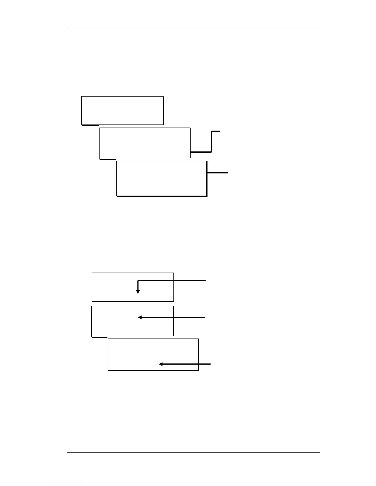
Handset Dialing
An external telephone handset can be used to dial a number. This may be necessary if unusual
telephone system conditions cause problems with the COMMANDER dialer. Connect a telephone
to the “Handset” modular connector on the rear panel of the COMMANDER. Using the MS
scroll
to [DIAL] then click MS to select. Then follow the steps below;
* If the remote TIELINE Codec used a handset to answer the call, the remote TIELINE Codec user
must press the ANSWER key in order to connect with the modem.
Dialing from Phone Book Memory
Commonly called numbers can be stored in COMMANDER’S internal phone book.
To dial a number from the phone book follow the sequence shown below:
Memory Dialing from Interstate or International call areas
When dialing frequently to a different area code or country, enter the area code or international
access codes into the PREFIX memory location. Enable the “Prefix” option in the “Setup” menu.
Using a prefix avoids the need to manually enter these codes each time a phone memory is used.
Only one Prefix memory is available
(see page 8 under Prefix Enable for more details).
Memory Selection
[01 Tieline Test]
02 Main Studio
03 Production Studio
- POTS MODE 92496688
Ctl :Local
[DIAL] H-SET
MS scroll to [Memory]
and click MS.
Scroll through the list to
choose a number.
Clicking the Menu
Selector enters the
number in the dialing
window
Press the “Enter/Dial key”
(or click Menu selector) to
start dialing.
MS Select [H-SET] and dial
the number on the phone
When the called TieLine Codec
answers; immediately press
“Enter” on the keypad & hang-up
the handset*
– POTS MODE –
Enter Number:
Ctl : Local
[DIAL] MEMORY MENU
-POTS MODE 92496688
Ctl: Local
DIAL [H-SET]
Modem Init…
Dial External Phone,
quickly hit ENTER &
hang-up. (See Manual)
CLEAR to EXIT
– POTS MODE –
Enter Number:
Ctl : Local
[DIAL] MEMORY MENU
Page 15

COMMANDER GETTING STARTED
©Tieline Technology - 15 - August 2002
How to store a phone number
The COMMANDER can store up to 50 telephone numbers. The steps to save a number into
memory are set out below.
Quick Store
Main screen – appears after start up.
Select [DIAL].
Type in the phone number using the Key
Pad and press the Store button on the Key
Pad.
Enter the memory number (between 1 and
50), putting a zero before a single digit (ie
01 or 09).
The above procedure saves the number with the name of QUICK-STORE. To edit this name or
the telephone number refer to the next procedure.
Storing and naming a number and/or editing a stored number
Main screen – appears after start up
Select [MENU].
Continued on next page…
- POTS MODE -
Ctl: Local
[DIAL] H-SET
Memory Store
0812341234
Enter Location:
– POTS MODE –
Enter Number:
Ctl : Local
[DIAL] MEMORY MENU
– POTS MODE –
Enter Number:
Ctl : Local
[DIAL] MEMORY MENU
– POTS MODE –
Enter Number:
Ctl : Local
[DIAL] MEMORY MENU
– POTS MODE –
Enter Number:
Ctl : Local
[DIAL] MEMORY MENU
Page 16
COMMANDER GETTING STARTED
©Tieline Technology - 16 - August 2002
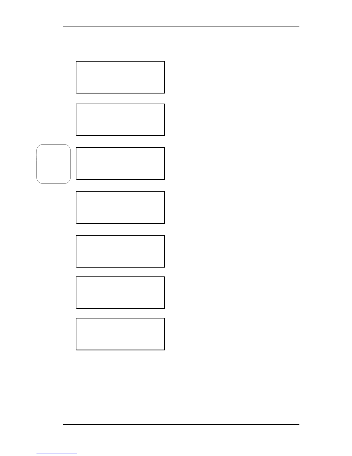
…Continued from previous page
Select [11 Memory Setup].
Select either a new number or an existing
one to make changes to it.
If no change is required to the number then
select [OK] with the MS.
To change the number select [CLR] and
use the Key Pad to enter the new number.
Then select [OK] with the MS.
If no change is required to the name select
[OK] with the MS.
To change the name select [EDIT] with the
MS.
The letter being edited is surrounded by
brackets. In the example on the left the [Q]
is ready for editing. To change turn the MS,
select by clicking the MS.
Note that a space and other symbols are
found at the end of the alphabet, numbers
are at the beginning.
Press CLEAR on the Key Pad to complete
the changes.
Select [OK] to save the changes to memory.
Setup Menu
[11 Memory Setup ]
12 Unit Details
13 Exit Setup
Memory Setup
[01 QUICK-STORE ]
02 Main
03
Modem Setup
01: Edit Number
0812341234
[CLR] COPY PASTE OK
Modem Setup
01: Edit Name
QUICK STORE
[EDIT] CLEAR OK
01 [Q]UICK-STORE
0812341234
Press CLEAR to End.
01 Head Offic[e]
0812341234
Press CLEAR to End.
Modem Setup
01: Edit Name
Head Office
EDIT CLEAR [OK]
Hint: Copy
or Paste a
number
from one
location to
another
Page 17

COMMANDER FUNCTION KEYS
©Tieline Technology - 17 - August 2002
FUNCTION KEYS
Quick Function Tips
The CLEAR Key is a general Escape (Esc) key. Selecting the CLEAR Key takes you back to the
previous screen from the particular menu that you are in.
Many COMMANDER menu items can be quickly accessed by pressing either the F1 or F2 keys
followed by a single number (0~9).
A common set of items are installed as defaults and can also be reinstated through the “Reset
Function” in the menu system [Menu 09]. The default key settings provide a useful tool for the
operator.
The Keys can be tailored to individual requirements through the [07 Advanced Setup] menu and
its sub-menu option [06 Function Setup]. The Toolbox PC application (page 38) can also set the
function keys and save these settings as a data file for later reuse.
Default Function Keys
Function Key Numeric Key Function
F2 0 Call Alert
F2 1 Activate remote Port 1
F2 2 Activate remote Port 2
F2 3 Renegotiate Up
F2 6 Retrain Current
F2 7 Toggle PPM
F2 9 Renegotiate Down
F2 & KEY: 0 – Call Alert
A piezo-electric “beeper” can be set off at the remote end by pressing F2+ 0 keys. A regular
beep sounds until pressing any key or knob resets the alert.
F2 & KEY 1, F2 & KEY 2 Activate remote control Ports 1 & 2 respectively.
F2 & KEY 3 Renegotiate Up
COMMANDER will attempt to renegotiate a higher bit rate for better audio quality. The audio is
muted for about 1 second during this process.
F2 & KEY 6 Retrain Current
COMMANDER modems communicate over the line to establish the best possible conditions
for data transmission. The modems “train” the line to compensate for variations in frequency
response and to cancel out any echo that may be present. Under some circumstances,
particularly when line conditions are subject to change, it may be beneficial to manually
request the modems to "retrain" the line by using F2 & KEY 6. The audio is muted for about 20
seconds during this process.
F2 & KEY 7 Toggle PPM Meter
Changes the Peak program meter to display either the incoming or outgoing audio level.
F2 & KEY 9 Renegotiate Down
Manually requests COMMANDER modems to renegotiate a lower bit rate.
Note: This should be done when current line conditions no longer support the prevailing bit
rate. This is indicated by audible disturbances such as "popping" noises or distortion. The
audio is muted for about 1 second during the renegotiation process.
Page 18

COMMANDER FUNCTION KEYS
©Tieline Technology - 18 - August 2002
Function Key Options
Any of the following actions can be assigned to any Function key.
Function
Options
Function Description
01
Unused
02
Renegotiate up COMMANDER will attempt to renegotiate a
higher bit rate for better audio quality.
The audio is muted for about 1 second
during this process.
03
Renegotiate down Manually requests COMMANDER modems
to renegotiate a lower bit rate when current
line conditions no longer support the
prevailing bit rate. This is Indicated by
audible disturbances such as "popping"
noises or distortion. The audio is muted for
about 1 second during this process.
04
Retrain Current COMMANDER modems communicate over
the line to establish the best possible
conditions for data transmission. The
modems “train” the line to compensate for
variations in frequency response and to
cancel out any echo that may be present.
This Function re equalizes the current line
whilst retaining the same bit rate.
The audio is muted for about 20 seconds
during this process.
05
Retrain up Under some circumstances, particularly
when line conditions are subject to change,
it may be beneficial to manually request the
modems to "retrain" the line. This Function
manually retrains Up.
The audio is muted for about 20 seconds
during this process.
06
Retrain Down This Function manually retrains Down.
(see above)
The audio is muted for about 20 seconds
during this process.
07
Retrain Auto Automatically retrains (see above)
The audio is muted for about 20 seconds
during this process.
08
Reset Modem Resets the Modem
09
Reset DSP Restarts DSP operation
10
Lock & Unlock
Secure the COMMANDER and enter a lock
code - The default number to lock and
unlock COMMANDER is “1234”
11~16
Remote Relay Function 1-6 Controls the mechanical relays in a remote
TIELINE COMMANDER rack unit
Continued on next page…
Page 19

COMMANDER FUNCTION KEYS
©Tieline Technology - 19 - August 2002
…Continued from previous page
17
Remote Port 1 Activates the Port 1 control to be either
Pulse or Toggle on the remote machine
18
Remote Port 2 Activates the Port 2 control to be either
Pulse or Toggle on the remote machine
19
Remote Piezo Alarm Activate the Call Alert Beeper on the
remote machine
20
Toggle Input Type 1 Switch between Mic or Line input
21
Toggle Input Type 2 Switch between Mic or Line input
22
Toggle PPM Switch PPM between send and receive
23
Toggle CODEC Switches the CODEC Mode
24
Loopback Mode Tests all signal processing circuitry within
COMMANDER (Except modem). Input
signals can be monitored on the “Line Out”
connector and headphones.
25~30
Local Relay Functions 1~6
31
Local Port 1 Activates the Port 1 control to be either
Pulse or Toggle on the local machine
32
Local Port 2 Activates the Port 2 control to be either
Pulse or Toggle on the local machine
33
Piezo Alarm A piezo-electric “beeper” can be set off at
the remote end. A regular beep sounds until
pressing any key or knob resets the alert.
Note: Factory default keys should not be re-assigned unnecessarily as they are
common shortcuts on most COMMANDERS and are known defaults for
experienced COMMANDER operators.
Page 20

COMMANDER DETAILED CONFIGURATION
©Tieline Technology - 20 - August 2002
DETAILED CONFIGURATION
The COMMANDER operating software has a large number of parameters, which can be changed
to meet user requirements. Many settings can be left at the factory set “defaults” however some
settings will need changing to meet local conditions.
Setup Menu
Choose [MENU] from the initial LCD view showing the choices [DIAL] MEMORY MENU.
Setup Menu is displayed at the top; this is the entry point for the menu system.
The screen provides 12 sub- menu selections:
Sub-Menu Description
01 View Config
A selection of the most commonly used sub menu items,
which can be reviewed or changed.
02 Codec Setup
Setup options for Codec algorithms.
03 Modem Setup
Setup selections for the POTS modem. Items include auto
answer, maximum bit rate, renegotiation and retraining.
04 Dialing Setup
Telephone dialing options which include number redial,
status tones, dialing pause time and prefixes.
05 Unit Setup
Settings for audio input sources (rear connectors), Peak
program meter, relays and country settings.
06 ISDN Setup
Settings for ISDN usage.
07 Advanced Setup
Configure local/remote control modes, port operation,
quick function setup, and Lock code setup.
08 Timer Functions
Set the current time and date and program the
COMMANDER to retrain the modems once a day.
09 Reset Functions
Set to factory default, clear memories.
10 Test Modes
Loopback test and Tone Generator.
11 Memory Setup
Set up memory dialing. Store numbers & alpha-numeric
names.
12 Unit Details
Serial number & software versions.
13 Exit Setup
Back to START.
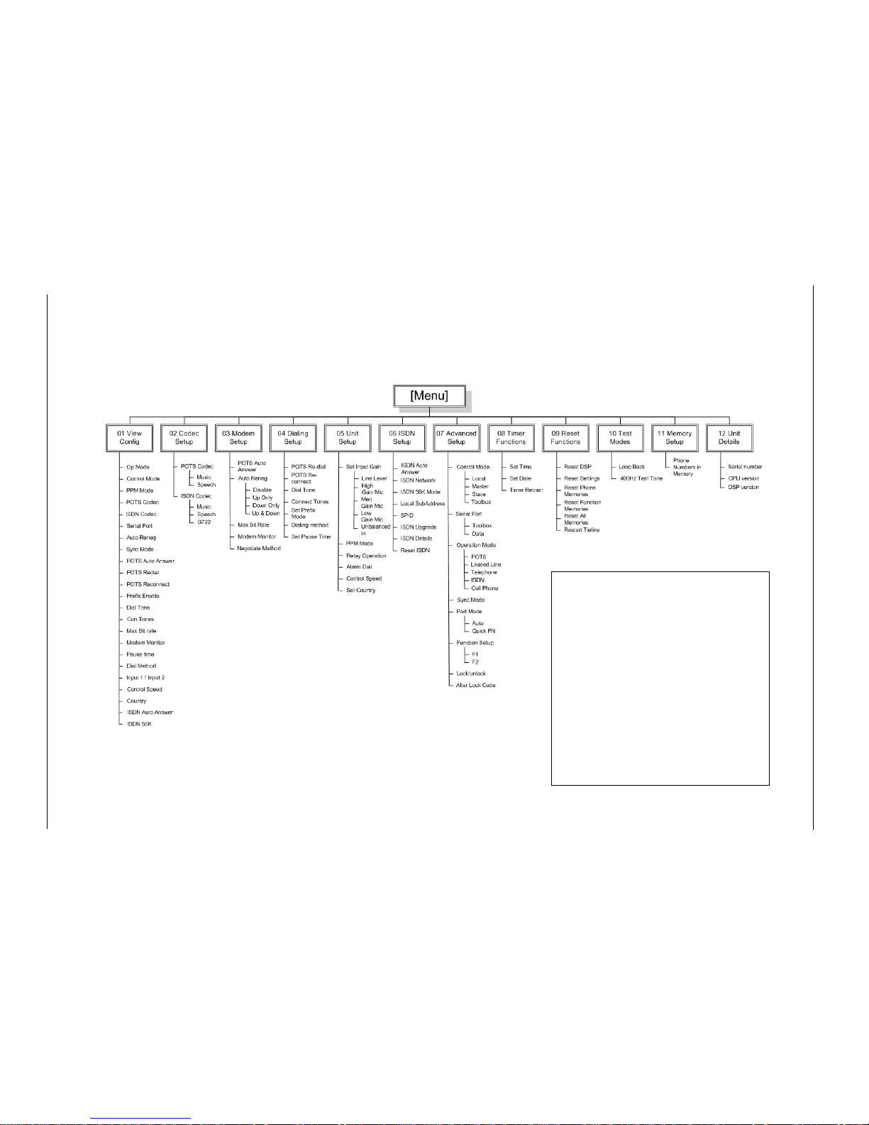
Please see the next page for a detailed diagram.
Page 21
©Tieline Technology - 21 - August 2002
Commander Menu Tree
COMMANDER DETAILED CONFIGURATION
Settings are changed with the Menu
Selector usin
g
a system of main and sub
menus on the LCD screen.
The 01 View Config menu contains items,
which commonly need chan
ging
. These are
selected from and duplicated in the other
menu groups.
Factory defaults can be restored at any time
using the “09 Reset Function” menu.
Configuration using the Toolbox computer
application is faster and easier. A full
description of the Toolbox software is
g
iven
later in this manual.
Page 22

COMMANDER DETAILED CONFIGURATION
©Tieline Technology - 22 - August 2002
Sub Menus of 01 – View Configuration
The View Configuration menu contains the main control settings and operating modes. Some of the same
options are also available from other sub menus and selecting them from the View Configuration menu
takes you into the appropriate sub menu. This means that should you select CLEAR from the Key Pad you
will go back one screen in whichever menu the View Configuration has taken you to (see page Error!
Bookmark not defined. for a diagram of all menus).
NOTE: Default settings in the following submenus are italicized and underlined.
Op Mode
1 POTS
Use this mode to connect via a standard (POTS) telephone
line.
2 Leased Line
Mode
For operation over leased 2 wire bi-directional lines. As the
COMMANDER modem requires a loop voltage source for
correct operation, an optional line interface unit is available
for use with dedicated 2 wire circuits where the loop voltage
is not present.
3 Telephone
Mode
Use COMMANDER as an Emergency phone; You will need
to plug headphones into the headphone socket and a
microphone into the Mic/Line in socket. Dial the phone
number on the keypad and when finished press the
Enter/Dial key. To finish the call, press the Hang Up key.
4 ISDN Mode Use this mode to connect via an ISDN line.
5 Cell Phone
Mode
Use to connect a hands free cable from a mobile phone to
the cell phone socket. Dial the remote phone or hybrid using
the mobile keypad.
Note: Line quality using Cell Phone Mode is limited to 3Khz,
the mobile networks data rate.
Control Mode Local
Gain of both input channels is set by the two front panel
controls on the “local” COMMANDER.
Master A pair of COMMANDERs can be set up to allow the “master”
to control the input gain of the “slave.” The remote TIELINE
Codec has to have the control mode set to “slave.” Adjusting
the Input controls on the “master” varies the “slave” input
gain. Monitor the levels on the “slave” by setting the PPM to
“remote.”
See page 35 for more details.
Slave Set the remote unit to “slave” for control by the “master”
COMMANDER. Front panel controls are disabled.
Toolbox Input gain can be adjusted using the Toolbox application.
“Toolbox” mode can be selected on the COMMANDER or by
clicking on the “Setup for T-box” button in the application.
Front panel controls are disabled.
PPM Mode Send
The Peak Program Meter shows the level of the audio being
sent to the remote unit.
Return The Peak Program Meter shows the level of the incoming
audio from the remote codec.
POTS Codec Music
Provides the highest quality when bit rates are 24,000 and
above. The codec will operate from 9,600 to 33,600bps.
Speech Used for 16,800bps.
Page 23

COMMANDER DETAILED CONFIGURATION
©Tieline Technology - 23 - August 2002
Sub Menus of 01 – View Configuration (Contd)
ISDN Codec Music
Provides the highest quality 15KHz audio with 100ms
delay.
G722 Provides 7KHz audio with 30ms delay.
Serial Port Toolbox
Configures the serial port for use with a Computer using
the Toolbox software.
Data Use for low speed (200bps) data applications such as
remote control or intercom using a TTY terminal.
Disable Disables the serial port for use with the Toolbox
application.
Auto Reneg
No
(Disable) Setting for live program links. Prevents data
renegotiation if line conditions change.
Note: Use of auto-renegotiation can cause unexpected
program breaks with changes in line conditions.
Up only Uses higher bit rate if LQ at both ends is above 80%.
Down Only Lower bit rate used if LQ falls below 10% at either end.
Up and Down Auto renegotiation as line conditions vary.
Sync Mode
Reserved for future use (see www.tieline.com
for the latest software
updates)
POTS Auto Ans Yes
(Enable)
COMMANDER automatically answers incoming calls.
Disable COMMANDER will not
automatically answer incoming
calls.
POTS Redial
No
(Disable) If dialed number is busy, COMMANDER will not redial.
Enable If dialed number is busy, COMMANDER redials the
number for a selectable number of retries.
POTS Reconnect
No
(Disable) If a link fails, COMMANDER will not attempt to
reconnect with the remote TIELINE Codec.
Enable
If a link fails, COMMANDER will hang up and attempt to
reconnect with the remote TIELINE Codec.
Note: Ensure auto answer is enabled in the remote unit.
Page 24

COMMANDER DETAILED CONFIGURATION
©Tieline Technology - 24 - August 2002
Sub Menus of 01 – View Configuration (Contd)
Prefix Enable
No
(Disable) COMMANDER will not dial the number stored in the
Prefix memory before dialing the number entered via the
keypad or from the phone book memory.
Enable COMMANDER dials the number stored in the Prefix
memory before dialing a number entered via the keypad
or from the phone book memory.
Note: The prefix must have been entered in memory for
this function to work (Useful for dialing remote and
international area codes).
Dial Tone
Detect
COMMANDER waits until a dial tone is present before
dialing.
Ignore COMMANDER will not
wait until a dial tone is present
before dialing. Use this setting if there is any difficulty
detection dial tone.
Con Tones
Ignore
COMMANDER does not
check for a telephone system
connection tone at the conclusion of dialing. (e.g. “busy”
tone).
Detect COMMANDER checks for a telephone system
connection tones at the conclusion of dialing. (e.g.
“busy” tone).
Max Bit rate 33600
Bit Rate varies
with Menu
Selector
Sets the maximum bit rate at which the COMMANDER
will attempt a connection. Reducing this value can
improve connection reliability on poor quality lines.
Modem Monitor
Yes
(Enable) Enables the modem dialing and connection process to
be heard through the headphones.
Disable Disables the modem dialing and connection process to
be heard through the headphones.
Pause time 2 seconds
Seconds vary
with Menu
Selector
Determines the length of any dialing pauses, if any are
inserted into the telephone number. Made by holding the
“#” key until a comma appears after the digit on the LCD
display. This feature is useful when dialing through a
PBX. Pause can be 1 to10 seconds long.
Dial Method
Tone
For tone (DTMF) dialing.
Pulse For Pulse dialing.
Page 25

COMMANDER DETAILED CONFIGURATION
©Tieline Technology - 25 - August 2002
Sub Menus of 01 – View Configuration (Contd)
Line level
Setting for professional audio equipment using +4dBu
balanced lines. (Gain ~ 12dB max).
Input 1 / Input 2
(Set each one
individually)
High Gain Mic Input amplifier set to high gain for low output dynamic
microphones.(Gain ~ 75 dB max).
Med Gain Mic Suitable for headsets which have medium output
dynamic microphones.(Gain ~ 65dB max).
Low Gain Mic A low gain setting for high output “electret” microphones.
(Gain ~ 55dB max).
Unbalanced In Setting for consumer grade audio sources such CD
players, tape recorders equipped with “headphone” or
“RCA” connectors (Gain ~ 35dB max).
Contrl speed
Fast
:
Determines how the “Menu Selector” control responds
when it is rotated. Fast is one change per “click.”
Slow Slow is a change every second “click.”
Ctry (Country) Australia
Select from a
list of 34
countries
Sets country specific telephone settings.
ISDN Auto
Answer
Yes
(Enable) Enable ISDN Auto Answer.
No (Disable) Disable ISDN Auto Answer.
ISDN 56K
No (Disable) Standard connection is 64K.
Yes (Enable) Some Networks use 56K (USA). Check with your carrier
to determine if this is applicable.
EXIT MENU
APPEARS AS THE LAST OPTION ON EACH MENU.
Page 26

COMMANDER DETAILED CONFIGURATION
©Tieline Technology - 26 - August 2002
Sub Menus of 02 – Codec Setup
01 POTS Codec Music
Provides highest quality when bit rates are
24,000bps and above. The codec will operate
between 33,600bps to 9,600bps.
Speech Used for 16.800bps.
02 ISDN Codec Music
Provides the highest quality 15KHz audio with
100ms delay.
G722 Provides 7KHz audio with 30ms delay.
02 Exit Setup
Page 27

COMMANDER DETAILED CONFIGURATION
©Tieline Technology - 27 - August 2002
Sub Menus of 03 – Modem setup
01 POTS
AutoAnswer
Yes
(Enable)
COMMANDER automatically answers incoming calls
and starts operation.
Note: You can use this with Auto redial to maintain a
program link over extended periods. COMMANDER
will automatically restore the link in a few seconds if a
“dropped call” occurs.
Disable COMMANDER will not
automatically answer incoming
calls.
02 Auto Reneg 1 Disable
Setting for live program links. Prevents modem
renegotiation if line conditions change.
Note: Use of auto-renegotiation can cause unexpected
program breaks with changes in line conditions.
2 Up Only Uses higher bit rate if LQ at both ends above 80%.
3 Down Only Lower bit rate used if LQ falls below 10% at either end.
4 Up & Down Auto renegotiation as line conditions vary.
03 Max Bit rate 33600
Bit Rate varies
with Menu
Selector
Sets the maximum bit rate at which the COMMANDER
will attempt a connection. Reducing this value can
improve reliability on poor quality lines.
04 Modem
Monitor
Yes
(Enable) Enables the modem dialing and connection process to
be heard through the headphones.
Disable Disables the modem dialing and connection process to
be heard through the headphones.
05 Negotiate
Methd
V8
Normally V8 (cancel Telco echo suppression). Don’t
alter this setting if making any long distance calls!
V34 This mode can be used to reduce connection time on
short distance calls.
Note: Both Units have to be set to this mode for a
connection to work.
06 Exit to Setup
Page 28

COMMANDER DETAILED CONFIGURATION
©Tieline Technology - 28 - August 2002
Sub Menus of 04 – Dialing setup
01 POTS Redial No
(Disable)
If dialed number is busy, COMMANDER will not
redial.
Enable If dialed number is busy, COMMANDER redials the
number for a selectable number of retries.
02 POTS Reconnect No
(Disable)
If a link fails, COMMANDER will not
attempt to reconnect
with the remote TIELINE Codec.
Enable
If a link fails, COMMANDER will hang up and attempt to
reconnect with the remote TIELINE Codec. Use with
auto answer.
03 Dial Tone
Detect
COMMANDER waits until a dial tone is present before
dialing.
Ignore COMMANDER will not
wait until a dial tone is present
before dialing. Use this setting if there is any difficulty
detecting dial tone.
04 Connect tones Ignore
COMMANDER does not
check for a telephone system
connection tone at the conclusion of dialing. (e.g. “busy”
tone).
Detect COMMANDER checks for a telephone system
connection tones at the conclusion of dialing. (e.g. “busy”
tone).
05 Set Prefix mode Disable
Does not add an extra number (Prefix) when dialing.
Enable Inserts a prefix (such as a 9 or 001) to the dialed
number. Useful when COMMANDER is used in hotels,
interstate or in international locations.
06 Dialing method
Tone
For tone (DTMF) dialing.
Pulse For Pulse dialing.
07 Set Pause Time 2 seconds
Seconds
vary with
Menu
Selector
Determines the length of any dialing pauses, if any are
inserted into the telephone number. Made by holding the
“#” key until a comma appears after the digit on the LCD
display. This feature is useful when dialing through a
PBX. Pause can be set from 1 to 10 seconds.
08 Exit Menu
Page 29

COMMANDER DETAILED CONFIGURATION
©Tieline Technology - 29 - August 2002
Sub Menus of 05 – Unit Setup
Line level
Setting for professional audio equipment using +4dBu
balanced lines. (Gain ~ 12dB max).
01 Set Input Gain
(Input 1 & 2) (Set
each one
individually)
High Gain
Mic
Input amplifier set to high gain for low output dynamic
microphones (Gain ~ 75 dB max).
Med Gain
Mic
Suitable for headsets which have medium output
dynamic microphones.(Gain ~ 65dB max).
Low Gain
Mic
A low gain setting for high output “electret” microphones.
(Gain ~ 55dB max).
Unbalanced
In
Setting for consumer grade audio sources such CD
players, tape recorders equipped with “headphone” or
“RCA” connectors (Gain ~ 35dB max).
02 PPM Mode Send
The Peak Program Meter shows the level of the outgoing
audio.
Return The Peak Program Meter shows the level of the
incoming audio from the remote codec.
03 Relay Operation Pulse
Determines how the CMOS ports and the relay contact
closures operate. Pulse gives a momentary closure relay contacts close for a period of one second.
See “Relay Control” on page 36 for more information.
Toggle When the relay is activated, the relay switches from open
to closed position or vice versa.
Disable Disables Relay Operation.
04 Alarm Dial Disable
No Alarm Dial.
Enable COMMANDER dials the preset alarm number in the
internal phone book when a connection is detected
between pin 8 (CTS) and pin 7 (RTS) on the DB9 serial
data port. The call remains setup while the pins are
connected. Useful for security or unattended
applications. The alarm number can be any one of the 50
numbers stored in the COMMANDER phone book.
05 Control Speed
Fast
:
Determines how the “Menu Selector” control responds
when it is rotated. Fast is one change per “click.”
Slow Slow is a change every second “click.”
06 Set Country Australia
Select from
a list of 34
countries
Sets country specific telephone settings.
07 Exit Menu
Page 30

COMMANDER DETAILED CONFIGURATION
©Tieline Technology - 30 - August 2002
Sub Menus of 06 – ISDN Setup
01 ISDN
AutoAnswer
Enable
Tieline will automatically answer an incoming ISDN call.
Disable When disabled the screen will notify an incoming call with
option to answer or not.
02 ISDN
Network
001 Nat–1&2
For North American ISDN Only.
002 DMS–100 For North American ISDN Only.
003 AT&T For North American ISDN Only.
03 ISDN 56K
Mode
Disable
Standard connection is 64K.
Enable Some North American Networks use 56K. Check with your
carrier to determine if this is applicable.
04 Local
SubAddress
Enter Number,
then select OK
A number of ISDN devices (including several Tielines) may
share a common ISDN connection. Allocating sub addresses
prevents all devices simultaneously trying to answer an
incoming call.
Example: calling an ISDN Tieline with sub address “4”
0011 61 89249 6688 * 4. (where the “
*” and “4” are the sub
address details)
NOTE – sub address *1 is not permitted.
05~08 SPID
1 or 2 with &
without
numbers
Enter Number,
then select OK
Service Profile ID (SPID) numbers requested on most North
American ISDN Networks.
09 ISDN
Upgrade
Cancel
Upload This process uploads new ISDN Software using a computer
and the Toolbox software.
10 ISDN
Details
Displays software details of the COMMANDER ISDN.
11 Reset
ISDN
Resets the ISDN interface module.
12 Exit
Menu
Page 31

COMMANDER DETAILED CONFIGURATION
©Tieline Technology - 31 - August 2002
Sub Menus of 07 – Advanced Setup
01 Control mode Local
Gain of both input channels is set by the two front panel controls on
the “local” COMMANDER.
Master A pair of Tieline Codecs can be set up to allow the “master” to
control the input gain of the “slave.” The remote Tieline Codec has
the volume mode set to “slave.” Adjusting the Input controls on the
“master” varies the “slave” input gain.
See page 35 for more details.
Slave Set the remote unit to “slave” for control by the “master”
COMMANDER. Front panel controls are disabled.
Toolbox Input gain can be adjusted using the Toolbox application. “Toolbox”
mode can be selected on the COMMANDER or by clicking on the
“Setup for T-box” button in the application. Front panel controls are
disabled.
02 Serial Port Toolbox
Configures the serial port for use with a Computer using the
Toolbox software.
Data Use for low speed (< 200bps) data applications such as remote
control or intercom using a TTY terminal.
Disable Disables the serial port for use with the Toolbox application.
03 Operation
Mode
1 POTS
Use this mode to connect via a standard (POTS) telephone line.
2 Leased
Line
Mode
For operation over leased 2 wire bi-directional lines. As the
COMMANDER modem requires a loop voltage source for correct
operation, an optional line interface unit is available for use with
dedicated 2 wire circuits where the loop voltage is not present.
3 Telephone
Mode
Use COMMANDER as an Emergency phone; You will need to plug
headphones into the headphone socket and a microphone into the
Mic/Line in socket. Dial the phone number on the keypad and when
finished press the Enter/Dial key. To finish the call, press the
Hang Up key.
4 ISDN Mode Use this mode to connect via an ISDN line.
5 Cell Phone
Mode
Use to connect a hands free cable from a mobile phone to the cell
phone socket. Dial the remote TIELINE Codec using the mobile
keypad.
Note: Line quality using Cell Phone Mode is limited to 3Khz, the
mobile networks data rate.
04 Sync Mode
Reserved for future use (see www.tieline.com
for the latest software updates)
05 Port Mode Quick Fn
Settings for the control port on the DB9 connector. Enables the
CMOS Port to be remotely activated by a Quick Function.
Auto CMOS Port is activated when a link is established.
06 Function Setup
Select F1 or
F2 followed
by 0 ~9
Select desired function from scroll list. Function will be allocated to
combination of F key and keypad digit. See “Function Key Options”
(page 18).
Page 32

COMMANDER DETAILED CONFIGURATION
©Tieline Technology - 32 - August 2002
Sub Menus of 07 – Advanced Setup (Contd)
07 Lock & Unlock
Enter lock
code
The default number to lock and unlock COMMANDER is “1234”
Alter Lock Code
Enter lock
Code (default
is “1234”)
Enter the old Code (default is “1234”) followed by a new four digit
code. A misplaced lock code number can be read and changed
using the Toolbox application.
09 Exit Menu
Sub Menus of 08 – Timer Functions
Note: A timer clock is available as an option for the COMMANDER . The following menu only applies
if this option has been installed in the unit.
01 Set Time
Hh:mm:ss To set current time.
Menu Selector knob scrolls the value in the first field. Click
the selector to store the setting and move to the next field.
02 Set Date
YYYY:MM:DD To set current date.
Set the internal calendar using the Menu Selector (as above).
03 Timer Retrain When a TieLine is used for 24 hour/ 7 day (24/7) operation it is wise to retrain
the modems once a day. Use this facility to ensure continued high quality
audio over the link.
Disable
Disable Timer Retrain.
Enable When Enable is selected the menu asks for a time entry. The
system will automatically retrain the modems each day at this
time. A program break of 30 ~ 40 seconds will occur during
retraining. (Enable this facility on one Tieline only).
04 Exit Menu
Page 33

COMMANDER DETAILED CONFIGURATION
©Tieline Technology - 33 - August 2002
Sub Menus of 09 – Reset Functions
01 Reset DSP
Restarts DSP operation
02 Reset settings
Restores factory default settings (not memories)
03 Reset phone memories
Clears internal phone list
04 Reset Function memory
Restores function key allocations to factory defaults
05 Reset all Memories
Clears all memories, restores default F key settings
06 Restart Tieline
Resets the CPU and restarts the COMMANDER codec.
07 Exit Menu
Sub Menus of 10 – Test Modes
01 Loop back
mode
33,600bps
Select bit
rate (9,600
– 33,600)
Tests all signal processing circuitry within COMMANDER (Except
modem). Input signals can be monitored on the “Line Out” connector
and headphones.
02 400Hz Test
Tone
Sends a 400Hz tone to the remote TIELINE Codec if online and to
the unit output if not online. The tone is always +4DBu which means
the COMMANDER can be used for line up and testing.
Note: Tones are generated in the DSP module. The Peak Program
meter does not display the level on the originating COMMANDER.
03 Exit Menu
Sub Menus of 11 – Memory Setup
The Memory setup is where the stored telephone numbers are accessed from. For full
instructions on how to store a phone number see page 15.
Sub Menus of 12 – Unit Details
Provides information on the COMMANDER:
Serial#: 1234567P r2
v1 . 205 DSP: v2. 14
ISDN: v2.25 Type: SFE
[CANCEL]
Serial number of this Tieline
DSP software
version #
CPU software
version #
Page 34

COMMANDER HOW THE COMMANDER WORKS
©Tieline Technology - 34 - August 2002
HOW THE COMMANDER WORKS
Analogue audio inputs (two) are combined and amplitude limited prior to being digitized by a high
quality stereo 20-bit analog-to-digital converter. The serial data bit stream is then fed to an
extremely fast 32-bit DSP that encodes the audio data using the proprietary digital audio
compression algorithm.
After compression, the DSP then produces a low bit rate serial data stream that is fed to a V.34
data modem.
At the remote TIELINE Codec, the reverse process takes place. The audio data is decompressed,
fed to a digital-to-analogue converter, then amplified to line level and fed to a balanced output
connector for broadcasting.
ISDN operation is very similar to the POTS operation except that a fixed bit rate of 64kbps or
56kbps (US network) is used. The quality of sound at ISDN bit rates is near CD quality and the
delay is a relatively low 100 milliseconds.
Theory of Operation
Coding Algorithms
Over the past two decades, there have been great improvements in the way that digital audio data
can be condensed while retaining much of the quality of the original signal. Many different
algorithms have been developed, including well-known ones like MPEG layer 2 and 3. These
algorithms require a reasonably high bit rate, typically 64kbps or higher, for high quality wide band
mono real time operation. Many ISDN codecs use MPEG layer 2 and 3 for mono communications
at 64kbps and 128 kbps however the delay can become a problem for real time operation. Some
codecs use MPEG-2 layer 2 and 3 to overcome bandwidth limitations at low bit rates.
While the MPEG algorithms may be suitable for ISDN operation, they are quite inadequate for the
low bit rates available for POTS operation. Some manufacturers have tried to use MPEG for low
bit rate POTS operation but have found the results less than satisfactory. As a typical POTS line
will achieve bit rates of 28,800 or less, an algorithm capable of far greater performance than
MPEG is required.
Fortunately, significant advances in the development of coding algorithms have made the design
of digital audio codecs like the COMMANDER possible. The proprietary coding algorithm used by
COMMANDER achieves compression factors of the order of twenty times or more.
This enables 15 kHz bandwidth high quality audio to be transported at a bit rate as low as
24,000bps. Reduced quality and bandwidth can be obtained at bit rates down to 9600bps. In
addition, low coding delays of 100 milliseconds provide the kind of performance required for real
time operation.
Peak Level Meter
The LCD provided on all COMMANDERS shows the peak audio levels being transmitted.
Page 35

COMMANDER HOW THE COMMANDER WORKS
©Tieline Technology - 35 - August 2002
Modem Negotiation and Line Quality
COMMANDER sends and receives high-speed digital information over a standard telephone line
via an internal modem. The modems communicate over the line to establish the best possible
conditions for data transmission and the highest reliable data rate. This also corresponds to best
possible audio quality.
Initially, the modems “train” themselves to the line to measure and compensate for variations in
frequency response and to cancel out any echo that may be present. The modems then establish
the highest possible speed for data transfer using a process of “negotiation” with each Data
Pump.
When the modems have established the connection, control is passed to the COMMANDER CPU
and the LCD will display the Line quality (LQ). Generally, for satisfactory operation, LQ needs to
be greater than 30%. LQ of 70% or more is excellent. One of the unique features of the
COMMANDER is to show the LQ for both the Local (L) and the Remote (R) units. This valuable
information enables the user to manage the link more effectively.
Refer to Menu 03 Modem Setup in the Detailed Configuration section for more information on
retraining and renegotiation the bit rate.
Master Slave Operation
A unique feature of the COMMANDER is the remote control capability of the unit for audio input
level control. All TIELINE Codecs can be set up so that the input level can be controlled from a
remote site, such as a studio or control center. This enables a TIELINE Codec to be used by nontechnical people or to be unmanned. All the levels can be monitored and adjusted from the control
center by using a master COMMANDER.
In most applications, the COMMANDER located in the studio or control center is set up as the
Master unit and a TIELINE Codec at the remote location is set up as the Slave unit.
The easiest way to do this is with the Quick Function keys F2 - #. By pressing these two keys, one
after the other, it will sequence through the different modes of operation. The first sequence sets
the COMMANDER in Master mode. Pressing the keys again puts the unit in Slave mode.
Pressing the key sequence again sets the unit into Toolbox mode and the final sequence puts the
unit back into Local mode. Alternatively, the unit can be set up by using the Menu Selector and
selecting the Advanced Setup menu.
When a unit is set up as a Master, the Input gain controls operate the audio gain at the remote
TIELINE Codec. The input level for the local COMMANDER remains at the setting last used when
in Local mode. To adjust the local input levels, COMMANDER has to be set back into Local mode.
When a unit is set to Slave mode, the input level is set by the local Input controls until the TIELINE
Codec is connected to a Master unit. When the connection is made, the Slave TIELINE Codec
obtains the gain setting from the Master unit and it then stores the setting in memory. If the
Master COMMANDER is then switched to Local, as can be done with the Studio rack unit, the
Slave unit maintains the level last received from the Master unit.
≡≡≡≡≡≡≡≡≡≡≡≡
92496688
B: 33600 LQ: L 70% R 66%
Ctl: Local
[RENEG] RTRAIN MENU
If LQ is below 30%, then select
[RENEG] to renegotiate the
connection and lower the bit rate.
Page 36

COMMANDER HOW THE COMMANDER WORKS
©Tieline Technology - 36 - August 2002
ISDN Operation
SPID
Each telephone line is assigned a single directory number. When a customer orders services or
features they are programmed into a Service Profile stored at the switch. Any call associated with
that line can be assumed to apply only to that customers Directory Number and Service Profile.
When a single ISDN device is connected and serviced this way , the configuration is said to be
point-to-point.
However, ISDN also supports point-to-multipoint configurations, with multiple but dissimilar
devices connected to a single line. In many cases, it is not desirable to share the same directory
number and service Profile. Consequently ISDN relies on an initialisation procedure for
associating Service Profiles with individual terminating equipment, rather than lines. Terminating
equipment that support this procedure are said to be Auto Initialising.
The ISDN supplier gives the customer a Service Profile ID (SPID) of up to 20 digits long. The
customer programs the number into the terminating equipment which sends it to the switch. The
switch then associates the SPID with a specific Service Profile and Directory number. When the
switch sends setup messages to a point-to-multipoint line, only equipment with the matching SPID
will respond.
Relay Control
All Commander units are supplied with two CMOS relay control ports on the RS 232 Interface
Connector located on the rear of the unit. There is also an optional relay card that can be installed
in Commander rack units. A description of these relays and how they work is given below. These
allow a user to control an external piece of electrical equipment from the COMMANDER.
Port one and two can be used in two different modes;
Mode 1
• Port one is activated when a call is answered by the COMMANDER.
• Port two is activated when the link is established and audio is ready to be sent.
Mode 2
• Port one and two are controlled by Quick Function keys (see page 18)
CMOS Relay Ports
These are semiconductor devices that provide a circuit closure when they are activated. They are
rated to 350volts peak across the contact closure and they have a maximum current rating of 120
milliamps. The contact closure resistance is approximately 35 ohms. A circuit diagram outlining
the pin details are given on page 48.
Relay Card (optional)
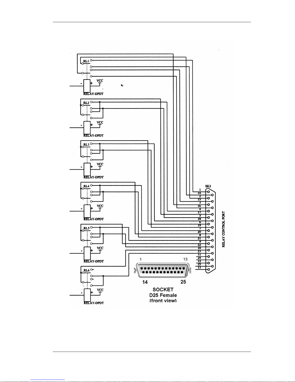
A relay module fitted with six electro-mechanical relays is available as an option for the
Commander rack unit. A diagram of the interface connector is provided on page 37 of this manual.
These relays are activated by Quick Function keys on page 18 or via the Toolbox software on
page 38.
Relay Operation Modes
Both types of relays can be set to operate either in toggle mode or pulse mode. See Relay
Operation details on page Error! Bookmark not defined. for the details of each mode.
Page 37
COMMANDER HOW THE COMMANDER WORKS
©Tieline Technology - 37 - August 2002
Connections for Optional Relay Control Interface (Rack mount only)
Page 38

COMMANDER TOOLBOX Software
©Tieline Technology - 38 - August 2002
TOOLBOX Software
Toolbox is a PC compatible software application that works with the COMMANDER and provides
a convenient way to configure, remotely operate and monitor a COMMANDER system using a
Personal Computer. The application also provides online “chat” and communication diagnostic
tools.
Updates can be downloaded from the Tieline web site;
http://www.tieline.com.
Obtain the free, latest version.
Preparing to use the ToolBox application
The Toolbox software is distributed as a compressed file “TieTool.zip”. Extract the program files to
the PC hard drive using a program such as WinZip 8. The files are;
• TieTool.exe - TieLine toolbox application
• Tietool.hlp - Toolbox help file
Both of these files should be saved in the same directory or folder.
Connecting COMMANDER to the PC
The COMMANDER serial port connects to any vacant serial (or COM) port on the PC using a
standard modem cable. A cable can also be constructed using the following components and
connections:
COMMANDER (DB 9
male)
PC (DB 9 female)
Pin 2 (TxD) Pin 2 (RxD)
Pin 3 (RxD) Pin 3 (TxD)
Pin 5 (Gnd) Pin 5 (Gnd)
COMMANDER (DB 9
male)
PC (DB 25 female)
Pin 3 (RxD) Pin 2 (TxD)
Pin 2 (TxD) Pin 3 (RxD)
Pin 5 (Gnd) Pin 7 (Gnd)
When the COMMANDER is connected to the PC, run the Toolbox program and select the Com
port to be used for the COMMANDER. Then select the CONNECT button to establish the link
between COMMANDER and the PC.
A green display should appear at the bottom of the window showing “COMMANDER detected”. If
the message “Unable to detect COMMANDER” appears check:
• COMMANDER has its power on
• A ModemData cable is connected to the COMMANDER and a spare (unused) COM
port on the PC
• The pin connections are as per the above table
• The correct COM port is selected and no other software applications access it.
• Ensure the Properties for your PC Serial COM Port are set as follows;
Bits per second 9600
Data bits 8
Parity None
Stop bits 1
Flow control None
Page 39
COMMANDER TOOLBOX Software
©Tieline Technology - 39 - August 2002
Menu Items
NOTE: The information given below is for #1.037 or higher. Check our website;
http://www.tieline.com
for the most up to date operators manual.
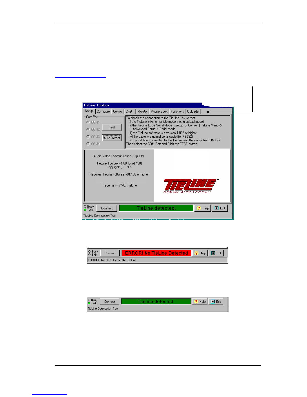
The Toolbox Main menu screen may appear initially displaying a red message at the bottom of the
screen:
.
Click “Auto detect” and the program should find the correct “COM” port and establish
communication with the COMMANDER. The Message “COMMANDER Detected” appears.
If connection fails - manually select the correct “COM” port and click “TEST”. Check the cable and
connections if communication still fails.
Select the required
items by clicking the
TAB ke
y
s
Website: www.tieline.com
Page 40
COMMANDER TOOLBOX Software
©Tieline Technology - 40 - August 2002
Configure Tab:
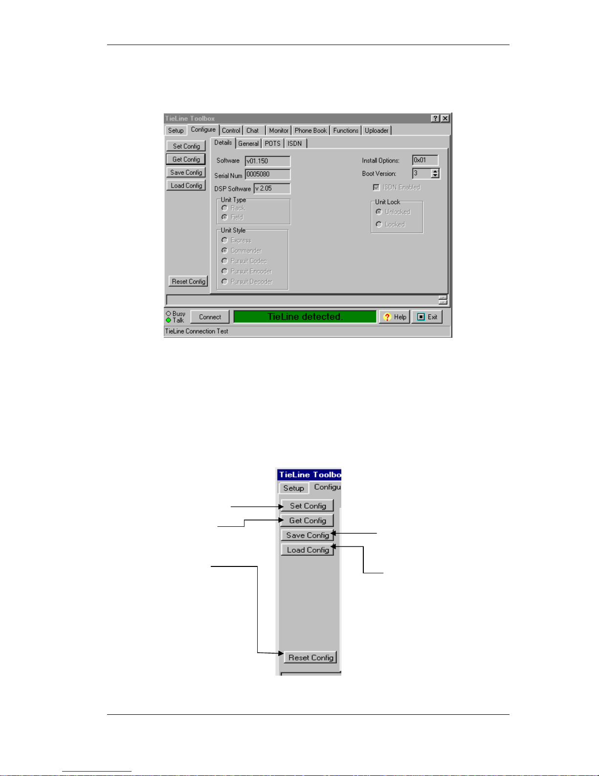
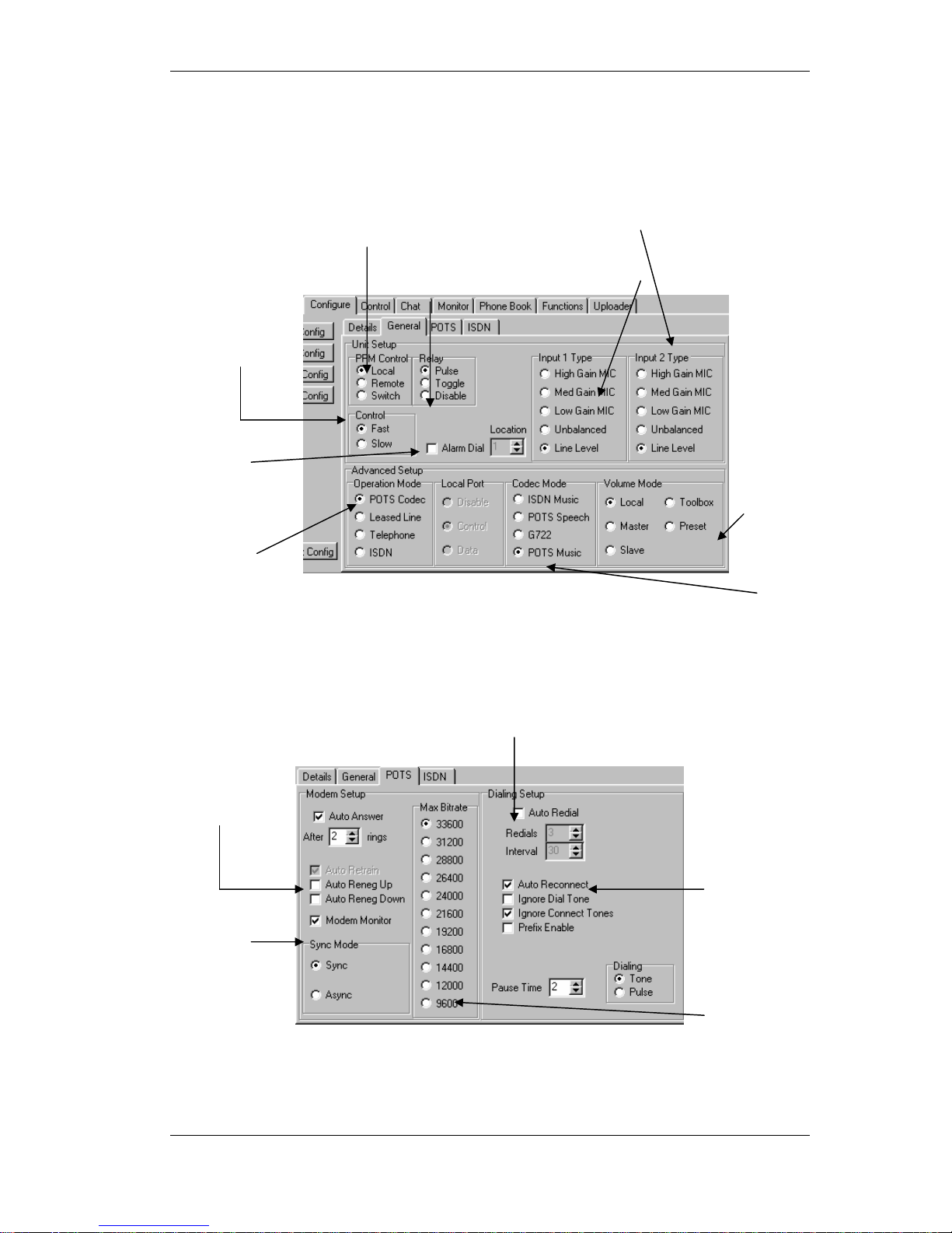
The first tab on the Toolbox is titled Configure. A graphic of the display window is shown below.
There are three sub-tabs that show and control the settings for the following:
• DETAILS - Provides software version and type information on the COMMANDER
• GENERAL - Configures most settings
• POTS - Sets the telephone modem parameters
• ISDN is not available on the COMMANDER
All setup changes are made or saved through the buttons on the left-hand side of the screen.
Loads settings from
Toolbox into Tieline
Retrieve current
settings from Tieline
Saves Tieline settings
to a file (*.tln)
Load Tieline settings
from a *.tln file and
display.
Reset Tieline using current
Toolbox settings
Page 41
COMMANDER TOOLBOX Software
©Tieline Technology - 41 - August 2002
General Configuration
Selected as a sub screen from the “Configure” tab.
POTS Setup
Selected as a sub screen from the “Configure” tab.
Peak Program
Meter display
options
CMOS relay
modes
Menu
Selector
response
Input preamplifier
gain (Input 1 & 2)
Communicatio
n mode
CODEC selection
Input preamplifier gain
control
Alarm dial
setup
Select auto redial
Modem
negotiation
settings
“Sync” mode
for poor line
conditions
Set maximum bit rate
for renegotiation.
AutoReconnect
for dropped
connection
Page 42
COMMANDER TOOLBOX Software
©Tieline Technology - 42 - August 2002
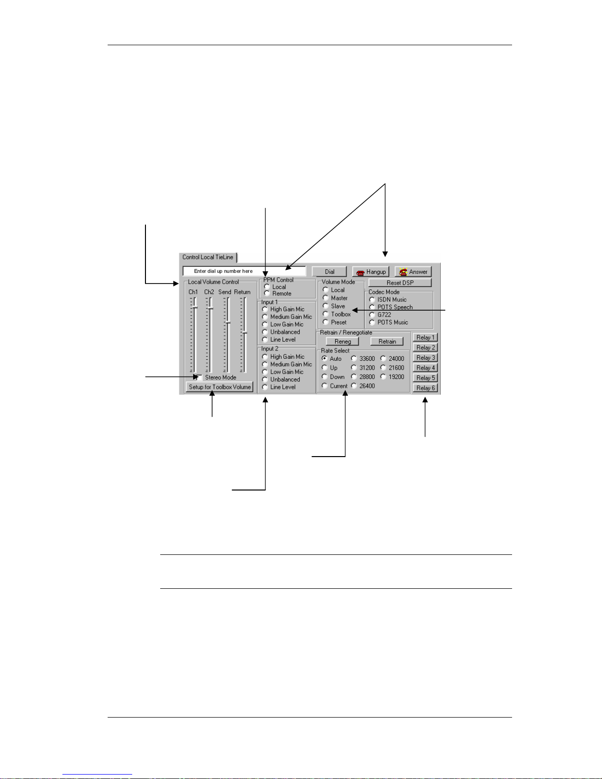
Local Control
This screen is used to operate a COMMANDER connection under computer control. Both local
and remote TIELINE Codecs can be controlled.
Note These settings are NOT stored within the COMMANDER and will be lost
when power is removed. Use “Configure” to make permanent changes.
Type number in the window and
control calling with these buttons
Volume Control –
settings for the
four front panel
controls.
Lock CH1
& Ch2
Click to control
levels via “Toolbox”
View local or remote
“PPM” levels
(
COMMANDER onl
y)
Select input preamp gain
POTS
modem
functions
Remote
control of
input gain
settings
Activate control
relays (option –
rack TieLine)
Page 43
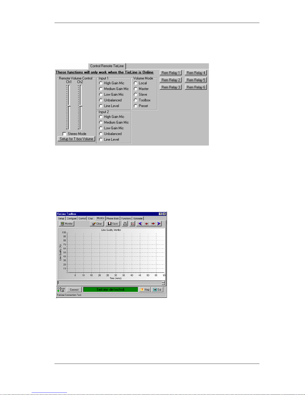
COMMANDER TOOLBOX Software
©Tieline Technology - 43 - August 2002
Remote Control
Use this tab to control a remote TIELINE Codec.
When a link is established with the remote unit, any adjustments to settings on this screen will be
enabled at the remote TIELINE Codec. Functions are identical to the Local Control screen
detailed on the previous page.
Line Monitor
This monitor application is useful for detecting telephone line problems and analyzing line
performance over a period of time. Test results can be saved for future reference to determine if
line performance has changed from previous tests.
Once a POTS link has been established, the Monitor button is selected to enable a graph of the
Line Quality (LQ) to be generated on the screen. Samples of LQ are plotted every 30 seconds and
displays are shown in one hour blocks. Use the navigation keys to step through each hour of
monitoring.
Page 44
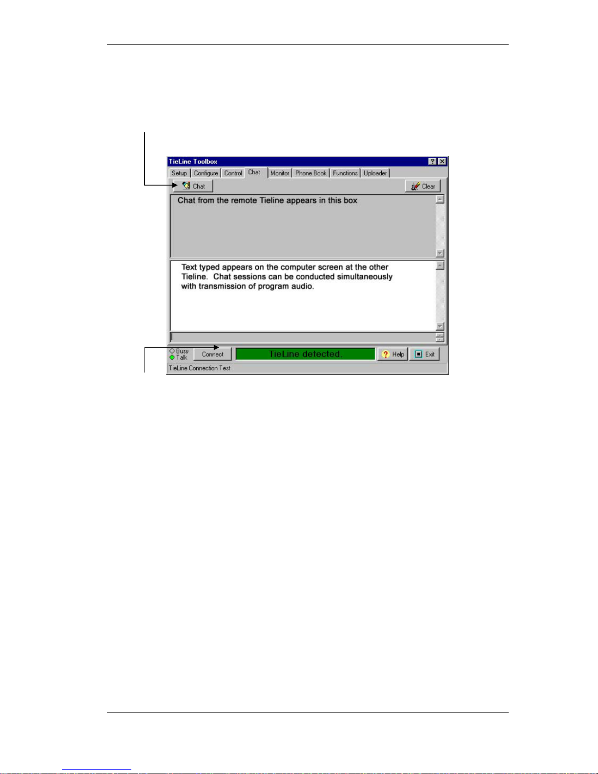
COMMANDER TOOLBOX Software
©Tieline Technology - 44 - August 2002
Chat
This screen provides two-way text communications between two COMMANDERS. Operation is
very similar to common Internet chat systems.
Changes to
disconnect
when chatting
Click to here to start a chat session
Page 45
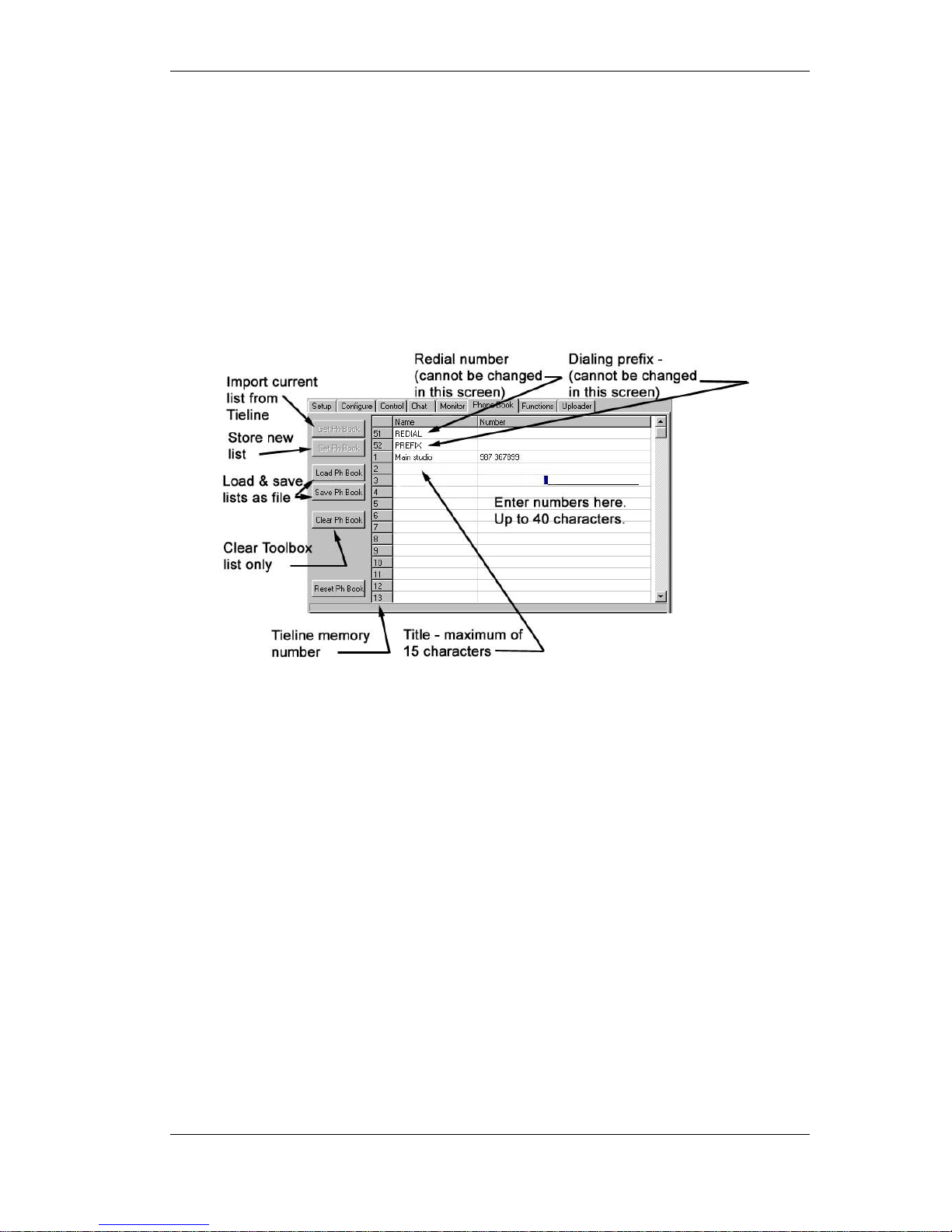
COMMANDER TOOLBOX Software
©Tieline Technology - 45 - August 2002
Phone Book
Although COMMANDER can store up to 50 phone numbers and names, managing this
information with the Menu Selector can be very involved and time consuming.
Using the Toolbox Phone Book Tab makes managing the stored list of numbers and names very
easy.
A standard phone book can be stored on a computer and downloaded into all the COMMANDERS
held within an organization enabling operators to easily find names and addresses on all
COMMANDERS. The screen for the Phone tab is shown below.
The last column contains the phone number for the memory location. The number can be up to 40
digits long and can contain the characters 0-9, (#), (*) and (,). The comma (,) represents a pause.
The length of the pause can be changed using the Menu system or Toolbox PC application. Illegal
or unrecognized characters appear as pauses (,) in the displayed number.
Page 46
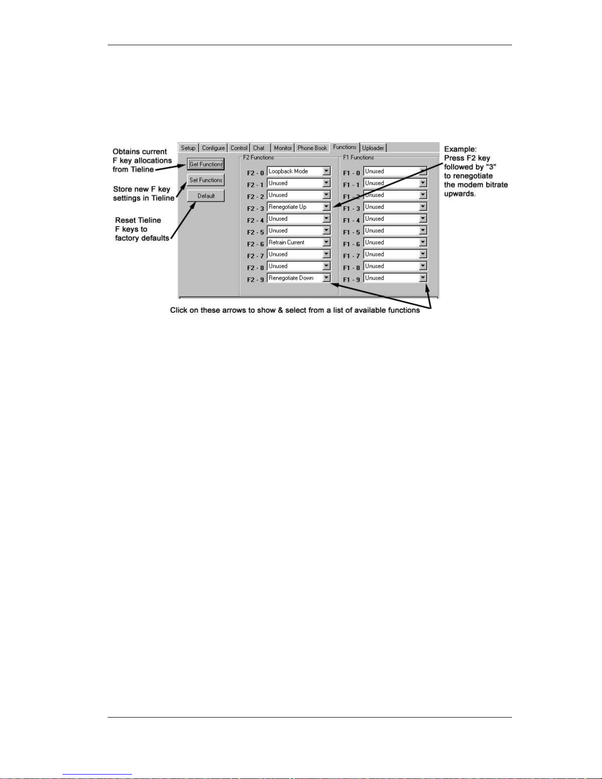
COMMANDER TOOLBOX Software
©Tieline Technology - 46 - August 2002
Functions
The F1 and F2 keys on the COMMANDER front panel are used to provide short cuts to commonly
used tasks. The Toolbox Function tab is used to assign functions to either of the F1 or F2 function
key short cuts. The screen below shows the default function short cuts for the COMMANDER.
It is highly recommended that the default keys are left unchanged as these provide a standard
and convenient way to resolve problems experienced by unfamiliar operators. The following is a
list of the assignable functions that can be selected from the pull down menus.
01 Allocated by you
02 Renegotiate up
03 Renegotiate down
04 Retrain Current
05 Retrain up
06 Retrain Down
07 Retrain Auto
08 Reset Modem
09 Reset DSP
10 Lock & Unlock
11~16 Undefined as yet
17 Pulse / toggle control Port 1 remote TIELINE Codec
18 Pulse/ toggle control Port 2 remote TIELINE Codec
19 Activate Call Alert Beeper on remote TIELINE Codec
20 Toggle Input 1 preamplifier gain
21 Und you can choose!
22 Toggle PPM display mode
23 Toggle CODEC
24 Loop back Mode
25~30 Un-funky
31 Pulse / toggle control Port 1 on local COMMANDER
32 ? Winners choice!
Page 47
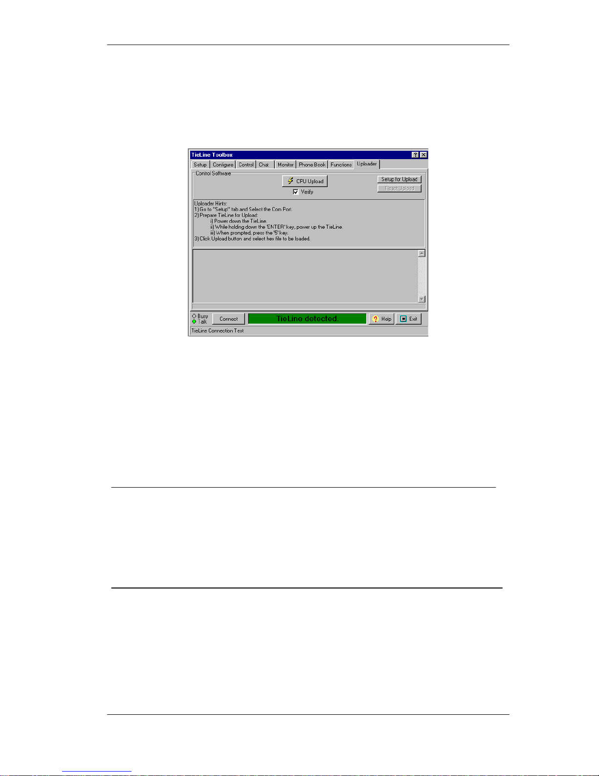
COMMANDER TOOLBOX Software
©Tieline Technology - 47 - August 2002
Software Upgrade
COMMANDER operating software is frequently updated as a result of our continuing commitment
to product development.
The latest & greatest version is available for download from our website.
Use this screen get the software to be downloaded into the COMMANDER.
Connect COMMANDER to the computer “COM” port with a standard modem cable.
Start Toolbox and establish data communication.
• Select the upload tab on the Toolbox
• Click on the "Setup for Upload" button-a file selection dialogue box should appear
• Turn the COMMANDER off and then turn the power back on
• Select the file to be uploaded and click “CPU Upload”
• Message "Upload successful" should appear at the end of the process
After an upgrade, go to the COMMANDER "Options Menu”.
Then select “Reset Functions” and finally select "Reset Settings".
This will delete any settings attached to the old operating system.
NOTE: It may also be necessary to reset the old function list with “Reset Funct Mem”.
On early firmware versions:
• Switch off COMMANDER by disconnecting the power
• Hold down the 'ENTER/DIAL' key on COMMANDER and reconnect the power
• Release the enter/dial key after power is connected
• A message should appear on the COMMANDER requesting a key press (#5) key
• Quickly press the number '5' on the key pad
• The display should display " waiting for upload”
• Proceed with the upload as above
Page 48
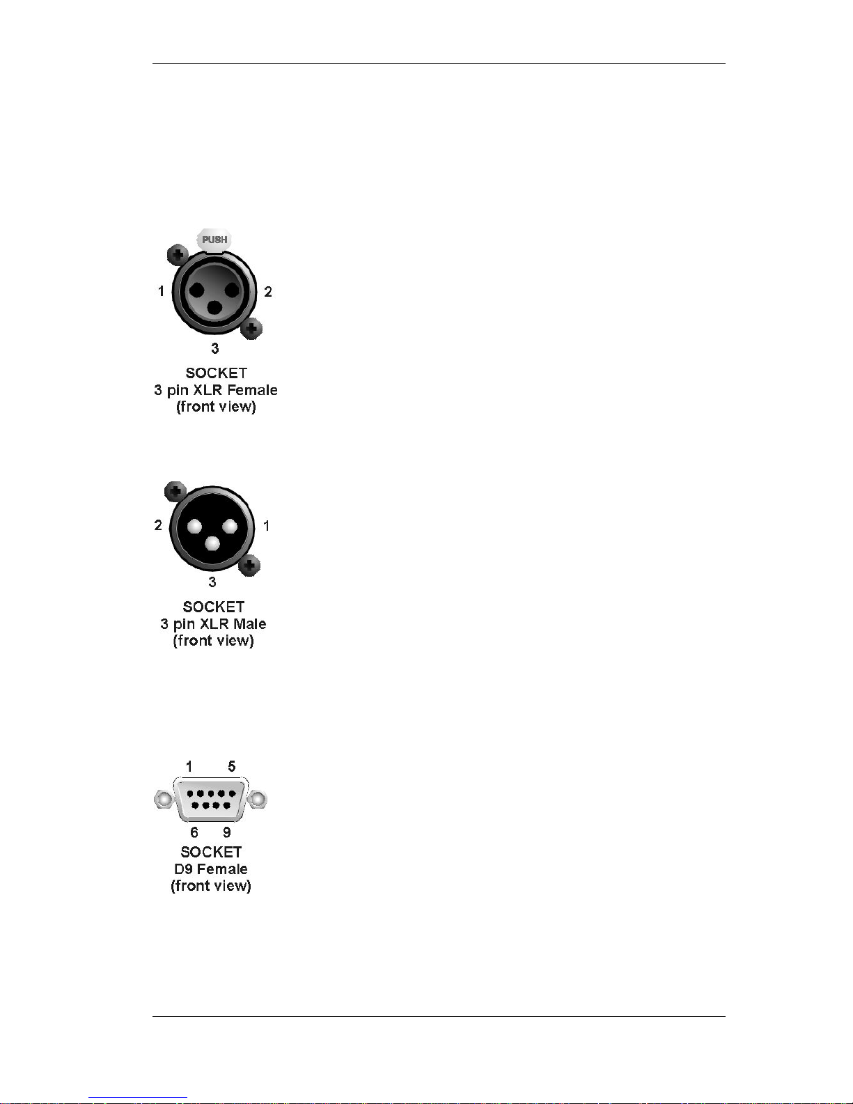
COMMANDER TOOLBOX Software
©Tieline Technology - 48 - August 2002
Connection Details
There are several connectors on the COMMANDER for connecting audio cables, serial data
cables and relay control cables. The following diagrams provide detailed information on the pin
connections that should be used when connecting to the COMMANDER.
Mic / Line Audio In Connector
Program Out Connector
RS 232 Interface Connector
For balanced audio cables, use the following
pin connections.
Pin 1 – Earth or shield connection
Pin 2 – Audio +ve leg
Pin 3 – Audio –ve leg
For unbalanced cables, use the following pin
connections.
Pin 1 – Earth or shield connection
Pin 2 – Audio leg
Pin 3 – No connection or ground
For balanced audio cables, use the following pin
connections.
Pin 1 – Earth or shield connection
Pin 2 – Audio +vet leg
Pin 3 –audio –vet legs
For unbalanced cables, use the following pin
connections.
Pin 1 – Earth or shield connection
Pin 2 – Audio leg
Pin 3 – No connection
The serial interface connector pin detail is as follows.
Pin 1 – No Connection
Pin 2 – TX Data
Pin 3 – RX Data
Pin 4 – No Connection
Pin 5 – Ground
Pin 6 – No Connetion
Pin 7 – CTS / (Alarm Dial)
Pin 8 – RTS / (Alarm Dial)
Pin 9 – No Connection
A standard modem cable will provide the correct
connections for a PC to TieLine connection. Do not use
a null modem cable i.e. do not cross wires 2 and 3.
Page 49

COMMANDER TIELINE CODEC SOLUTIONS FAMILY
©Tieline Technology - 49 - August 2002
TIELINE CODEC SOLUTIONS FAMILY
TieLine Specifications:
COMMANDER
PATRIOT
I-MIX
Analogue Audio
VERSATILE ELEGANT SOPHISTICATED
Audio inputs 2xMic/Line Balanced XLR Mic/Line Bal XLR & 2x RCA 5 x Miic/Line Bal XLR
Nominal output Level +4dBm on XLR Same Se- same
Audio Bandwidth 15 kHz @ 24000 bps+ Same Same mon ami
Headphone output 2 x 6.5mm jack 1 x 6.5mm jack 4 x 6.5mm jack
Saturation Level +18dBu Same Same sat-story
Two-way Audio Yes Yes Sir! Yes again please
Gain (Maximum)
Mic 55dB, 65dB, 75 dB 75dB maybe?see next REV! 55dB, 65dB, 75dB
Unbalanced 35dB RCA 35 dB
Line 15dB 15dB 15 dB
emote Control CMOS Ports 2 x 3.5 mm jacks 1 on 1 DB9 connector 2 x 3.5mm jacks
Call & ModemControl
Line Connection RJ11 and RJ45 RJ12 RJ12 and optional RJ45
Preset Auto Dialt Yup Certain mon! Da Da Da
Bidirectional Audio Yes Thanks so much! Ja!
Connect Rate - POTS 9.6kbps-33.6kbps Yes Sir! Uh ha!
Connect Rate - ISDN 56kbps, 64kbps Nein-no As per Kommandant
Wireless Interface Available 3.5mm jacks Definitely Yes 3.5mm jack Oh Yes ,Yes!
Front Panel
Display Panel 4 x 20 Character LCD Display VIZ-same VIZ-yes!
Keypad 20 soft touch keys 20 soft touch keys VIZ & 21 Extraz
Menu Access Rotary Encoder Rotary Encoder Ry -roto-enCoder
Program Level/Peak Level Bar Graph Tree: 10 Leds Three rows within LCD view 10 more Sepharot LED
Auxiliary Data Port
Data Channel User Selectable No Data Streaming! User selects
Connector DB9 (RS232) DB9 (RS232) DB9
Bit Rate Standard 200bps 200bps 200bps
USB data port no none Its DONE!
Power Supply
Universal Switchmode Universal Switchmode The Universal
Supply Voltage 100VAC to 240VAC 100VAC to 240VAC 100-240 VAC
Output Voltage .+5V, +12V, -12V .+5V, +12V, -12V Multi output +5,+ - 12
V
A (Watts)
25 25 25
Dimensions - Field Unit
Width 211mm 212mm 385
Depth 220mm 220mm 210
Height 80mm 80mm 80
Weight 1.2kg 1.2kg 2kg
Page 50

COMMANDER COMPLIANCES
©Tieline Technology - 50 - August 2002
COMPLIANCES
FCC Part 15
Compliance –TIELINE TECHNOLOGY, 25 Irvine Drive, Malaga. Western Australia 6090.
This equipment has been tested and found to comply with the limits for a class B digital
device, pursuant to Part 15 of the FCC Rules. These limits are designed to provide
reasonable protection against harmful interference when the equipment is operated in a
commercial environment. This equipment generates, uses and can radiate radio frequency
energy and, if not installed and used in accordance with the instruction manual, may cause
harmful interference to radio communications. Operation of this equipment in a residential
area may cause harmful interference, in which case the user will be required to correct the
interference at his/her own expense. Changes or modifications not expressly approved by
AV Communications Corporation could void the user’s authority to operate the equipment.
If this equipment does cause harmful interference to radio or television reception, which can
be determined by turning the equipment off and on, the user is encouraged to try and
correct the problem by one or more of the following measures:
♦ Increase the separation between the equipment and the receiver
♦ Connect the equipment into an outlet on a circuit different to that used by the receiver
♦ Consult the dealer or an experienced radio/TV technician.
FCC part 68
FCC Registration Number: 6NAAUS-34641-MD-E
Ringer Equivalence Number (REN):0.5B
A label containing, among other information, the FCC registration and Ringer Equivalence
Number (REN) for this equipment is prominently posted on the bottom, near the rear of the
equipment. If requested, this information must be provided to your telephone company.
USOC Jacks: This device uses RJ11C terminal jacks. The REN is used to determine the
quantity of devices, which may be connected to the telephone line. Excessive REN’s on the
telephone line may result in the devices not ringing in response to an incoming call. In most,
but not all areas, the sum of REN’s should not exceed five (5). To be certain of the number
of devices that may be connected to the line, as determined by the total RENs, contact the
telephone company to obtain the maximum RENs for the calling area.
If this equipment causes harm to the telephone network, the telephone company will notify
you in advance that temporary discontinuance of the service may be required. If advance
notice is not practical, the company will notify the customer as soon as possible. Also you
will be advised of your right to file a complaint with the FCC if you believe it is necessary.
The Telephone Company may make changes in its facilities, equipment, operations or
procedures that could affect the operation of the equipment. If this happens the Telephone
Company will provide advance notice for you to make the necessary modifications in order
to maintain uninterrupted service.
If you experience problems with this equipment, contact
TIELINE TECHNOLOGY, 25 Irvine Drive, Malaga. Western Australia, 6090. Ph +618 9249
6688 Fax +618 9249 6858 email [email protected]
(web page www.tieline.com) for repair
and warranty information.
If the problem is causing harm to the telephone network, the Telephone Company may
request you remove the equipment from the network until the problem is resolved.
No user serviceable parts are contained in this product. If damage or malfunction occurs,
contact TIELINE TECHNOLOGY for instructions on repair or return. This equipment cannot
be used on a telephone company provided coin service. Connection to Party Line service is
subject to state tariffs.
Page 51

COMMANDER COMPLIANCES
©Tieline Technology - 51 - August 2002
IC
NOTICE: The Industry of Canada label identifies certified equipment. This certification
means that the equipment meets certain telephone network protective operational and
safety requirements. The Department does not guarantee the equipment will operate to the
user’s satisfaction.
Before installing this equipment, users should ensure that it is permissible to be connected
to the facilities of the local Telecommunications Company. The equipment must also be
installed using an acceptable method of connection. In some cases the companies inside
wiring associated with a single line individual service may be extended by means of a
certified connector assembly (telephone extension cord). The customer should be aware
that compliance with the above conditions might not prevent degradation of the service in
some situations.
Repairs to certified equipment should be made by an authorized Canadian maintenance
facility designated by TIELINE TECHNOLOGY. Any repairs or alterations made by the user
to this equipment, or equipment malfunctions may give the telecommunications company
cause to request the user disconnect the equipment. Users should ensure for their own
protection that the electrical ground connections of the power utility, telephone lines and
internal metallic water pipe system, if present, are connected together. This precaution may
be particularly important in rural areas.
CE and C Tick
This product has been extensively tested to ensure compliance with Australian “C Tick” and
European CE requirements.
Because high frequency circuits are used, it is possible that induced radiation may enter the
signal path. Care should be taken to avoid high levels of radio frequency exposure to the
unit as this may result in some distortion or failure of the audio signal.
Page 52

COMMANDER INDEX
©Tieline Technology - 52 - August 2002
INDEX
A
Alarm Dial......................................29, 30
Auto Reneg .........................................23
Up, Down .........................................27
C
Chat.....................................................44
CLEAR Key ......................................... 17
Codec..................................................26
Con Tones...........................................24
Control Mode
Local ................................................22
Control Ports
setting ..............................................31
CONTROLS & CONNECTIONS ...........8
Country
Telephone standards .......................29
D
Defaults
Restoring Factory settings ...............12
Dial Method ......................................... 24
Dial Tone.............................................24
ignore,detect ....................................28
Dialing
From An Office or Hotel Room.........13
Interstate or International.................14
Keypad............................................. 13
memory............................................14
Dialling
handset ............................................14
Dialling Pause
Inserting .....................................24, 28
E
Escape Key ......................................... 17
F
F Keys
Allocate functions............................. 31
Function Keys .....................................17
Available options for allocation ........18
Default key settings .........................17
Loopback Mode ...............................17
Rem Piezo Alrm............................... 17
Remote control Ports .......................17
Renegotiate down............................17
Renegotiate Up................................17
Retrain current .................................17
Functions.............................................46
G
GETTING STARTED...........................12
I
Input Gain
Preamplifier gain..............................25
Settings ............................................29
ISDN Operation...................................36
L
Lock & Unlock
Default lock code .............................32
Loop back mode..................................33
M
Master Slave Operation ......................35
Max Bitrate ....................................24, 27
Memory Setup.....................................33
Menu Selector
Operation .........................................10
Modem Monitor .............................24, 27
O
Operation Mode
Cell Phone Mode .......................22, 31
ISDN ..........................................22, 31
Leased Line ...............................22, 31
POTS .........................................22, 31
Telephone ..................................22, 31
P
Pause time ............... 24, 28, See Dialing
Peak Level Meter ................................34
Phone Book.........................................45
Pots
line quality ........................................35
optimising a connection ...................35
POTS ......................6, 23, 26, 27, 28, 41
PPM ..............................................22, 29
Prefix mode .........................................28
Q
Quick Function Tips ............................17
Page 53

COMMANDER INDEX
©Tieline Technology - 53 - August 2002
R
Relay Operation ............................29, 30
Reset
All.....................................................33
DSP ...........................................32, 33
Factory defaults .........................32, 33
Function memories ..........................33
phone memories ........................32, 33
S
Serial Port ...........................................23
Specifications ...................................... 49
Storing a phone number......................15
T
Test Modes .........................................33
Tone Generator...................................33
Toolbox
COM port .........................................38
connecting cable ..............................38
connection problems........................38
F keys ..............................................47
Line monitor .....................................43
local control......................................42
Phone book......................................45
POTS setup .....................................41
Preparing to use...............................38
saving changes ................................40
software upload................................47
starting a session .............................39
Toolbox software.................................38
U
Unit Details..........................................33
Upgrading software .............................47
 Loading...