

Tieline Commander G3 TLR300, Commander G3 TLR303 Reference Manual

TLR300 Rack Unit Mixer-CODEC
and TLR303 Front Panel
Reference Manual
(Incorporating the TLG3 Graphical User Interface)
Commander G3 Rack Unit Reference Manual Version 4.1
Software Version: Tieline Toolbox V.4.14.48 RPTP version 104
Firmware Version: 1.6.72; RPTP version 104
November, 2012
IMPORTANT: Please read page 2 for important
firmware update information
ToolBox Software Note: We recommend using a LAN or serial connection
when installing ToolBox G3 software on operating systems other than
XP. Please read http://www.tieline.com/Support/toolbox-G3
before
attempting to connect ToolBox via USB.

Recent Manual Updates
Tieline
Page 2
T E C H N O L O G Y
Important Updates for Firmware v.1.6.72 RPTP 104
1. From the 31st March 2011 Tieline has discontinued support for the Voice G3
algorithm. As a result it has been omitted from this v.1.6.72 firmware release
and all codecs purchased after this date. Codecs with firmware v.1.6.72 or
higher can connect to G3 codecs running older firmware versions, but will
have to use an algorithm other than Voice G3. Voice G3 is usually used for
low-bitrate connections over GSM and POTS. We recommend using Tieline
Music as a substitute for these low bit-rate connections.
2. It is now possible to configure a ‘Hangup Profile’ in G3 codecs. This means a
codec can receive calls from other codecs that change its existing connection
profile, and then the codec receiving the call will automatically return to the
preprogrammed Hangup Profile after disconnection. Program this via
[Menu] > [Configuration] > [Advanced] > [Hangup Profile]
and select the
profile.
3. A new version of Toolbox v.4.14.48 is now available to support firmware
release v.1.6.72. (Download from Tieline support at
http://www.tieline.com/Support/Latest-Firmware/Current-G3-FirmwareVersions.)
4. TLR300B2 codecs now support 256Kbps MP2 J-Stereo connections at
32KHz and 48KHz sampling over IP and X.21.
5. References to “RAW” uncompressed data are now renamed “PCM” in G3
codecs for consistency with new Tieline codecs.
6. Telstra 3G Wireless Access Points have been renamed for Australian
customers.
Previous Name
New Name
Telstra per MB
Telstra datapk
Telstra Timed
Telstra PC Pack
Telstra Per KB
Telstra internt
7. Other access points have been added for Australia and Canada.
Country
New Access Point Number
Australia
Telstra extrant
Canada
Bell HSDPA
Canada
Telus (SP)
Canada
SaskTel HSDPA

Table of Contents
Tieline
Page 3
T E C H N O L O G Y
Table of Contents
SECTION 1. SAFETY NOTICES AND WARNINGS ............................................... 15
SECTION 2. MANUAL CONVENTIONS ................................................................. 16
2.1. CONTROLS ........................................................................................................... 16
2.2. CONNECTOR PANEL ............................................................................................ 16
2.3. MENU TEXT ......................................................................................................... 16
2.4. MENU NAVIGATION ............................................................................................. 16
2.5. TOOLBOX SOFTWARE ......................................................................................... 16
2.6. HYPERLINKS ........................................................................................................ 16
SECTION 3. WELCOME TO OUR REVOLUTION ................................................ 18
SECTION 4. INTRODUCTION TO TIELINE CODECS ......................................... 20
4.1. FEATURES IN RELEASE VERSION 1.4.XX ............................................................ 21
4.2. FEATURES IN RELEASE VERSION 1.6.XX ............................................................ 22
4.3. FEATURES OF THE COMMANDER G3 FIELD UNIT CODEC: ............................... 24
4.4. DATA OPTIONS AVAILABLE ................................................................................ 25
4.5. COMPATIBILITY ACROSS THE G3 RANGE OF CODECS ...................................... 26
SECTION 5. CONFIGURATION OF THE RACK UNIT CODEC ......................... 27
SECTION 6. FIELD UNIT AND RACK UNIT DIFFERENCES .............................. 28
SECTION 7. FUNCTIONALITY OF THE COMMANDER G3 RACK UNIT ........ 29
7.1. DATA OPTIONS AVAILABLE ................................................................................ 29
SECTION 8. NEW CODEC MENU WIZARDS ........................................................ 32
8.1. EASIER NAVIGATION ........................................................................................... 32
8.2. MODULE INDICATOR ARROWS ........................................................................... 33
8.3. CODEC MODULE OPTIONS ................................................................................. 34
SECTION 9. QUICK START: CONNECTING QUICKLY USING MANUAL
DEFAULT PROFILES .......................................................................... 36
9.1. STEP 1: SET AUDIO CONFIGURATION SETTINGS ............................................... 37
9.2. STEP 2: SELECT A PROFILE ................................................................................. 39
9.3. STEP 3: CHANGE CONNECTION SETTINGS ........................................................ 41
9.4. GETTING CONNECTED ........................................................................................ 57
9.5. 10 SIMPLE STEPS TO CONNECT TIELINE CODECS (VERSION 1.6.XX ....................
FIRMWARE OR HIGHER) ....................................................................................... 59
9.6. QUICK START PROCEDURE FOR 3G IP CONNECTIONS (VERSION 1.6.XX
FIRMWARE OR HIGHER
) ....................................................................................... 62
9.7. REMOTE CONTROL OF INPUT CONTROLS .......................................................... 64
9.8. CONFIGURING REMOTE CONTROL VIA CODEC MENUS .................................... 65
9.9. ADJUSTING LOCAL (MASTER CODEC) AND REMOTE (SLAVE CODEC) INPUT
LEVELS WHEN IN REMOTE CONTROL CHANNEL MODE ................................... 66
9.10. USING THE MENU SELECTOR FOR REMOTE LEVEL CONTROL ......................... 66
9.11. RESET REMOTE CONTROL .................................................................................. 66
9.12. CODEC REMOTE CONTROL MENU STRUCTURE ................................................ 67
SECTION 10. POTS OPERATION AND USAGE TIPS: HOW IT WORKS ........ 68
10.1. HISTORICAL REFLECTIONS ................................................................................. 68

Table of Contents
Tieline
Page 4
T E C H N O L O G Y
10.2. MODEM NEGOTIATION AND LINE QUALITY FOR POTS MODE ........................ 69
10.3. POTS OPERATION PRECAUTIONS ..................................................................... 69
10.4. CALL WAITING .................................................................................................... 69
10.5. PRIVATE BRANCH EXCHANGES (PBX), PRIVATE AUTOMATIC BRANCH
EXCHANGES (PABX), BUSINESS SYSTEMS ........................................................ 70
10.6. LINE CHECKS ...................................................................................................... 70
10.7. EARTH LEAKAGE PROBLEMS ON THE LINE ........................................................ 71
10.8. EQUIPMENT PROBLEMS AT THE CO OR LOCAL EXCHANGE ............................. 71
10.9. TIPS FOR SUCCESSFUL OPERATION ................................................................... 72
10.10. POTS VERSUS NEW POTS G3 MODULES..................................................... 73
10.11. STABILITY OF TIELINE POTS MODULES ....................................................... 74
10.12. MAKING POTS VOICE CALLS ........................................................................ 77
10.13. WHY MAKE POTS VOICE CALLS? ................................................................. 78
10.14. SELECTING POTS VOICE MODE .................................................................... 78
10.15. ROUTING POTS VOICE CALLS TO A CODEC’S ANALOG OUTPUTS ............. 80
10.16. POTS SUMMARY: ........................................................................................... 81
SECTION 11. ISDN OPERATION .......................................................................... 82
11.1. IMPORTANT CONSIDERATIONS ........................................................................... 82
11.2. WHAT ISDN MODULE DO I NEED? ..................................................................... 82
11.3. HOW DO I INSTALL THE ISDN MODULE? ........................................................... 83
11.4. CONNECTING OVER ISDN .................................................................................. 84
SECTION 12. GSM OPERATION ........................................................................... 90
12.1. HOW DOES IT WORK? .......................................................................................... 90
12.2. HSCSD INFORMATION COURTESY OF GSMWORLD.COM ................................ 90
12.3. WHAT DO I NEED FOR GSM? .............................................................................. 90
12.4. DEFAULT GSM CONNECTION SETTINGS ........................................................... 91
12.5. CONFIGURING GSM CONNECTIONS USING A GSM MODULE ......................... 91
12.6. CONFIGURING GSM CONNECTIONS VIA THE RS 232 SERIAL PORT ............... 92
12.7. CONFIGURING A POTS LANDLINE CODEC FOR GSM CONNECTIONS ............. 94
12.8. A FINAL NOTE ON GSM CONFIGURATION ........................................................ 95
SECTION 13. 3GIP ................................................................................................... 96
SECTION 14. SATELLITE OPERATION ............................................................... 97
14.1. BROADBAND GLOBAL AREA NETWORK (BGAN) ............................................. 97
SECTION 15. X.21 OPERATION............................................................................ 98
15.1. HOW DO X.21 MODULES CONNECT TO THE NETWORK?................................. 98
15.2. HOW DOES IT WORK? ......................................................................................... 98
15.3. CONNECTING VIA X.21....................................................................................... 99
SECTION 16. IP STREAMING CONFIGURATIONS ......................................... 100
SECTION 17. OPERATION OF YOUR CODEC: CODEC LCD DISPLAYS .........
AND DIALING CONNECTIONS .................................................. 101
17.1. GETTING STARTED: OPERATING THE MENU SELECTOR (MS) ........................ 101
17.2. CLEAR ................................................................................................................ 102
17.3. AUDIO MONITORING ON THE CODEC .............................................................. 102
17.4. PRE-FLIGHT CONNECTION CHECKS ................................................................. 102
17.5. MENU NAVIGATION ........................................................................................... 102
17.6. GETTING STARTED ............................................................................................ 103

Table of Contents
Tieline
Page 5
T E C H N O L O G Y
17.7. THE LCD SCREEN ON INITIAL POWERUP ........................................................ 103
17.8. LOADING PROFILES ........................................................................................... 103
17.9. INITIAL CONNECTION STATE OF CODEC LCD DISPLAYS ............................... 105
17.10. INITIATING MANUAL CONNECTIONS: DIALING A NUMBER ......................... 108
17.11. MANUAL ISDN CONNECTIONS .................................................................... 111
17.12. MANUAL GSM CONNECTIONS ..................................................................... 112
17.13. MANUAL 3G CONNECTIONS ........................................................................ 113
17.14. MANUAL IP CONNECTIONS .......................................................................... 114
17.15. MANUAL X.21 CONNECTIONS ..................................................................... 115
17.16. THE CONNECTIONS MANAGER (CXNS) ...................................................... 116
17.17. SUMMARY: ..................................................................................................... 118
17.18. MENU SETTINGS ........................................................................................... 119
17.19. MENU: SUBMENU DETAILS .......................................................................... 121
SECTION 18. DATA TRANSFER & USING 3RD PARTY DEVICES ................. 146
18.1. DATA OPTIONS AVAILABLE .............................................................................. 146
18.2. THE SERIAL PORT DATA WIZARD..................................................................... 146
18.3. AN INTRODUCTION TO SESSION DATA............................................................. 146
18.4. SOME BACKGROUND ON DATA PACKETS ........................................................ 146
18.5. THE OSI MODEL EXPLAINED ........................................................................... 147
18.6. THE SESSION LAYER ......................................................................................... 148
18.7. HOW TIELINE CODEC SESSION DATA WORKS................................................. 148
18.8. CONFIGURING THE SERIAL PORT TO SEND DATA ........................................... 151
18.9. ENABLING SERIAL PORT DATA FLOW CONTROL ............................................ 151
18.10. GSM TRANSPARENT AND NON-TRANSPARENT DATA MODES ................... 152
18.11. DTMF CONTROL OF 3
RD
PARTY DEVICES ................................................... 153
SECTION 19. RELAY AND CONTROL PORT OPERATION ........................... 155
19.1. EXTERNAL RELAY BOX ..................................................................................... 155
19.2. CABLING AND OPERATION DISTANCES ............................................................ 156
19.3. CAN BUS CABLE TERMINATIONS .................................................................... 157
19.4. INPUTS ............................................................................................................... 157
19.5. OUTPUTS ........................................................................................................... 157
19.6. SETUP ................................................................................................................ 157
19.7. DIP SETTINGS ................................................................................................... 158
19.8. CMOS RELAY OPERATIONAL MODE ............................................................... 158
19.9. FRONT PANEL LED INDICATORS ..................................................................... 158
19.10. PIEZO ALARM ................................................................................................ 158
SECTION 20. TOOLBOX OPERATION .............................................................. 159
20.1. TOOLBOX SOFTWARE DOWNLOADS ................................................................ 159
20.2. PREPARING TO USE TOOLBOX SOFTWARE WITH YOUR CODEC .................... 160
20.3. CONNECTING YOUR CODEC TO A PC .............................................................. 161
20.4. CONFIGURING TOOLBOX AND YOUR CODEC TO WORK TOGETHER ............. 161
20.5. CONNECTING TOOLBOX VIA USB ................................................................... 162
20.6. LAN CONNECTION: STATIC, DHCP AND BOOTP IP ADDRESSES ............... 164
20.7. INSERTING STATIC IP ADDRESSES INTO A CODEC AND PC ............................ 164
20.8. SERIAL PORT CONNECTIONS: CONFIGURATION AT THE CODEC ITSELF ........ 166
20.9. CONNECTING YOUR CODEC TO TOOLBOX SOFTWARE ................................... 167
20.10. UPDATING FIRMWARE................................................................................... 169
20.11. OPERATION OF THE TLG3 GUI ................................................................... 172

Table of Contents
Tieline
Page 6
T E C H N O L O G Y
20.12. CONNECTING THE GUI TO THE CODEC ...................................................... 174
20.13. GUI VIEWS: TILE, CASCADE & RESIZE ........................................................ 176
20.14. USING THE GUI TO CONTROL THE 1RU COMMANDER G3 ....................... 179
SECTION 21. CONFIGURATION FILE SYSTEM .............................................. 182
21.1. THE RELATIONSHIP BETWEEN CONFIGURATION FILES, PROFILES AND
MATRICES .......................................................................................................... 182
21.2. DIFFERENT CODEC CONFIGURATION FILES ..................................................... 183
21.3. SET, GET, SAVE AND OPEN FUNCTIONS OF CONFIGURATION FILES .............. 184
SECTION 22. MATRIX EDITOR ........................................................................... 185
22.1. AN OVERVIEW ................................................................................................... 185
22.2. HOW DO I USE MATRICES IN THE CODEC? ...................................................... 185
22.3. ROUTING MATRICES EXPLAINED ...................................................................... 186
22.4. ACTIVATING THE MATRIX EDITOR .................................................................... 187
22.5. MATRICES –WHERE DO I START? .................................................................... 187
22.6. DEFINING THE MATRIX EDITOR ........................................................................ 189
22.7. CHECKING OF CROSS POINTS ........................................................................... 189
22.8. THE DEFAULT MATRICES ................................................................................. 190
22.9. CREATING, SAVING AND AMENDING MATRICES .............................................. 191
22.10. ADDITIONAL EDIT MATRIX FUNCTIONS ....................................................... 192
22.11. ALL MATRICES MENU FUNCTIONS .............................................................. 192
SECTION 23. PROFILE EDITOR ......................................................................... 193
23.1. USER PROFILES ................................................................................................. 193
23.2. SET FACTORY DEFAULTS .................................................................................. 194
23.3. MANUAL DEFAULT PROFILES: OVERVIEW ....................................................... 194
23.4. SELECTING MANUAL DEFAULT PROFILES ....................................................... 196
23.5. GENERAL ATTRIBUTES OF MANUAL DEFAULT PROFILES ............................... 196
23.6. CURRENT RUNTIME: OVERVIEW ....................................................................... 197
23.7. MANUAL DEFAULT PRESETS ............................................................................ 197
23.8. MANUAL DEFAULT MONO PROGRAM .............................................................. 198
23.9. MANUAL DEFAULT MONO/IFB ....................................................................... 199
23.10. MANUAL DEFAULT STEREO ......................................................................... 201
23.11. MANUAL DEFAULT DUAL PROGRAM ........................................................... 202
23.12. MANUAL DEFAULT BONDED MONO ............................................................ 202
23.13. CREATING A NEW PROFILE ........................................................................... 203
23.14. PROPERTIES .................................................................................................. 203
23.15. HOW DO I UTILIZE PROFILE MASKS? .......................................................... 204
23.16. COPY AND PASTE FUNCTIONS ..................................................................... 204
23.17. DELETING A PROFILE .................................................................................... 205
23.18. RENAMING A PROFILE ................................................................................... 205
23.19. MAKING ADJUSTMENTS WITHIN PROFILES .................................................. 205
SECTION 24. CONNECTION SETUP ................................................................. 207
24.1. THE CONNECTION MANAGER ........................................................................... 207
24.2. CONNECTION NO. ............................................................................................. 208
24.3. BONDING: AN OVERVIEW ................................................................................. 208
24.4. DIALING BONDED MONO CONNECTIONS ........................................................ 209
24.5. ISDN 3B AND 4B BONDING ............................................................................ 211
24.6. CONFIGURING 4B CHANNEL CONNECTIONS .................................................. 212
24.7. CONNECTION TYPE ........................................................................................... 213

Table of Contents
Tieline
Page 7
T E C H N O L O G Y
24.8. CODING AND ALGORITHMS .............................................................................. 216
24.9. MPEG EXPLAINED ............................................................................................ 218
24.10. TIELINE ALGORITHMS AVAILABLE ............................................................... 221
24.11. SAMPLERATE ................................................................................................. 224
24.12. ALGORITHM CONNECTION MATRIX ............................................................. 225
24.13. PORTS AND CODEC CHANNELS: AN OVERVIEW .......................................... 228
24.14. PHONEBOOK NUMBERS ............................................................................... 230
24.15. AUTOMATIC REDIAL ..................................................................................... 231
24.16. FAILOVER PROFILE IN DETAIL ...................................................................... 232
24.17. REMOTE PROFILE .......................................................................................... 239
24.18. A TYPICAL CONNECTION SETUP PROCEDURE ............................................ 239
SECTION 25. POTS TAB ....................................................................................... 240
25.1. POTS AND POTS G3 MODULE DIFFERENCES ............................................... 240
25.2. SELECT POTS INTERFACE ................................................................................ 241
25.3. OPERATING MODE ............................................................................................ 241
25.4. AUTO RENEGOTIATE: OVERVIEW ..................................................................... 242
25.5. MODEM MAX BIT-RATE ..................................................................................... 242
25.6. MONITOR ENABLE ............................................................................................. 243
25.7. DETECT DIAL TONE .......................................................................................... 243
25.8. DETECT PROGRESS TONE ................................................................................. 243
25.9. DISABLE LINE QUALITY .................................................................................... 243
25.10. QUICK NEGOTIATION ENABLE: OLD POTS MODULE ONLY ..................... 244
25.11. DIAL METHOD............................................................................................... 244
25.12. LEASED LINE ................................................................................................. 244
25.13. AUTO ANSWER .............................................................................................. 245
25.14. DIAL PAUSE TIME ......................................................................................... 245
25.15. MANUAL DEFAULT ALGORITHM .................................................................. 245
SECTION 26. GSM LL/GSM/USB-3G ................................................................ 246
26.1. GSM CONNECTIONS ......................................................................................... 246
26.2. 3G CONNECTIONS ............................................................................................ 247
26.3. SELECT GSM LANDLINE INTERFACE ............................................................... 247
26.4. OPERATING MODE ............................................................................................ 247
26.5. GSM LANDLINE PRE BUFFER SECS ................................................................. 248
26.6. GSM LANDLINE BITRATE ................................................................................. 248
26.7. MANUAL DEFAULT GSM LANDLINE ALGORITHM .......................................... 249
26.8. GSM MODULE/CELLPHONE SETUP: SELECT GSM INTERFACE (FOR A ..............
CODEC CONNECTING WITH A GSM CONNECTION) .......................................... 249
26.9. GSM WIRELESS NETWORK TYPE ..................................................................... 249
26.10. GSM PRE BUF SECS (FOR A CODEC CONNECTING WITH A GSM
CONNECTION
) ................................................................................................ 250
26.11. GSM BITRATE (FOR A CODEC CONNECTING WITH A GSM CONNECTION) . 251
26.12. MANUAL DEFAULT GSM ALGORITHM (FOR A CODEC CONNECTING
WITH A
GSM CONNECTION) ......................................................................... 251
26.13. SIGNAL STRENGTH ENABLE AND RESET WAIT SECONDS ........................... 251
26.14. A FINAL NOTE ON GSM CONFIGURATION .................................................. 251
SECTION 27. ISDN ................................................................................................ 252
27.1. SELECT ISDN INTERFACE ................................................................................. 253
27.2. ISDN NETWORK TYPE ...................................................................................... 253

Table of Contents
Tieline
Page 8
T E C H N O L O G Y
27.3. ISDN LINE TYPE ............................................................................................... 254
27.4. ISDN LOCAL SUBADDRESS .............................................................................. 254
27.5. SPID EXPLAINED .............................................................................................. 255
27.6. SPID1, SPID2 (SERVICE PROFILE ID) ............................................................ 255
27.7. DN1, DN2 AND MSN NUMBERS ..................................................................... 255
27.8. AUTO ANSWER ................................................................................................... 256
27.9. PHANTOM POWER DETECT ............................................................................... 256
27.10. MANUAL DEFAULT ALGORITHM .................................................................. 256
27.11. SAMPLERATE ................................................................................................. 256
SECTION 28. IP/LAN AND SIP TABS ................................................................ 258
SECTION 29. X.21 .................................................................................................. 259
29.1. SELECT X.21 INTERFACE .................................................................................. 259
29.2. X.21 LINK TYPE ................................................................................................ 259
29.3. BIT RATE ............................................................................................................ 259
29.4. MANUAL DEFAULT ALGORITHM ...................................................................... 260
29.5. SAMPLE RATE .................................................................................................... 260
29.6. X.21 CALL CONTROL TYPE .............................................................................. 261
SECTION 30. INPUTS ........................................................................................... 262
30.1. INPUT GAINS ..................................................................................................... 262
30.2. INPUT TYPES ..................................................................................................... 262
30.3. ADDITIONAL INPUT SETTINGS .......................................................................... 263
30.4. PHANTOM POWER ............................................................................................. 263
30.5. INTELLIGENT GAIN CONTROL .......................................................................... 264
30.6. ROUTING VOICE CALLS TO A CODEC’S ANALOG OUTPUTS ........................... 265
30.7. PHONE INPUT: OPERATION OF THE I-MIX G3 PHONE COUPLER ................... 266
30.8. AUXILIARY INPUT .............................................................................................. 268
30.9. LOCAL AND REMOTE CODEC LEVEL ADJUSTMENT WITH TOOLBOX
SOFTWARE ......................................................................................................... 268
30.10. CONTROL MENU: ADJUSTING INPUT LEVELS USING TOOLBOX ............... 269
SECTION 31. REMOTE CONTROL ..................................................................... 270
31.1. LOCAL AND REMOTE CODEC OPERATION EXPLAINED ................................... 270
31.2. REMOTE CONTROL OF INPUT GAINS ................................................................ 271
31.3. PROFILE REQUIREMENTS FOR REMOTE CONTROL .......................................... 272
31.4. CONFIGURING THE REMOTE (SLAVE) CODEC TO BE CONTROLLED ............... 272
31.5. CONFIGURING THE LOCAL (MASTER) CODEC TO CONTROL THE REMOTE
CODEC ............................................................................................................... 273
31.6. ADJUSTING LOCAL (MASTER CODEC) AND REMOTE (SLAVE CODEC) INPUT
LEVELS WHEN IN REMOTE CONTROL CHANNEL MODE ................................. 274
31.7. ACCEPT REMOTE CUE ....................................................................................... 274
31.8. GANG TO KNOB ................................................................................................. 276
SECTION 32. OUTPUTS ....................................................................................... 277
32.1. PPM DISPLAYS ................................................................................................. 277
32.2. AUX OUTPUT (HP1 BALANCED MONO OUTPUT) ........................................... 281
32.3. MIX (SEND/RETURN) PAN MATRIX .................................................................. 281
32.4. TALK BACK LEVEL ADJUSTMENT ..................................................................... 282
32.5. AUTOMATIC GAIN CONTROL ............................................................................ 282
32.6. RELATIONSHIP OF IGC TO AGC ...................................................................... 282

Table of Contents
Tieline
Page 9
T E C H N O L O G Y
SECTION 33. FUNCTIONS ................................................................................... 284
33.1. CREATING A NEW USER FUNCTION.................................................................. 286
33.2. ACTIVATION RULE ............................................................................................. 287
33.3. SOME ACTIVATION RULE EXAMPLES ............................................................... 296
33.4. TASK RULE ........................................................................................................ 297
33.5. PRESET USER FUNCTIONS ................................................................................ 311
33.6. EDIT FUNCTION ................................................................................................. 317
33.7. DELETE FUNCTION ............................................................................................ 317
33.8. SOFTKEY MENU DISPLAY ................................................................................. 317
33.9. A FINAL NOTE… ................................................................................................ 317
SECTION 34. MATRIX MAP TAB ........................................................................ 318
34.1. MATRIX MANAGEMENT – A THREE STEP PROCESS ........................................ 318
34.2. MATRIX MAPPING – AN OVERVIEW .................................................................. 319
34.3. ‘MAPPING’ MATRICES FOR CODEC FUNCTIONS .............................................. 320
34.4. CUE: AN OVERVIEW .......................................................................................... 321
34.5. CUE/COMMS IN PREFADE OR OFF-LINE MONITORING MODE ........................ 322
34.6. CUE/COMMS AS ‘LOCAL’ INTERCOM ............................................................... 322
34.7. USING CUE/COMMS AS ‘LOCAL’ INTERCOM IN STEREO ................................ 323
34.8. CUE AS CODEC-TO-CODEC INTERCOM ............................................................. 323
34.9. TALKBACK ......................................................................................................... 324
34.10. REMOTE CUE................................................................................................. 325
34.11. PHONE AS TALKBACK ................................................................................... 326
34.12. CREATING PROFILES ..................................................................................... 326
SECTION 35. VIEW MATRIX TAB ....................................................................... 327
35.1. VIEW MATRIX MENU ......................................................................................... 327
35.2. AN EXAMPLE: INTEGRATED COMMUNICATIONS WITH A TIELINE
BROADCAST CODEC .......................................................................................... 328
SECTION 36. UNIT OPTIONS TAB ..................................................................... 330
36.1. COUNTRY SELECTION ....................................................................................... 330
36.2. POWERUP CONSOLE ......................................................................................... 330
36.3. AUTO RECONNECT ............................................................................................ 331
36.4. AUDIO REFERENCE LEVEL ................................................................................ 331
36.5. BONDING TYPE ................................................................................................. 331
36.6. SESSION DATA ENABLE .................................................................................... 331
36.7. AUTO SOFTKEY ENABLE ................................................................................... 332
SECTION 37. GLOBAL UNIT SETTINGS TAB.................................................. 333
37.1. UNIT LOCK ........................................................................................................ 333
37.2. SPEED DIAL ....................................................................................................... 333
37.3. POWERUP PROFILE ........................................................................................... 334
37.4. POWERUP PROFILE: MANUAL DEFAULT PROFILE SETTINGS .......................... 334
37.5. SERIAL PORT MODE .......................................................................................... 335
37.6. SERIAL PORT RATE ........................................................................................... 335
37.7. SERIAL PORT FLOW CONTROL ......................................................................... 336
SECTION 38. PHONEBOOK EDITOR ................................................................ 337
38.1. NAME AND NUMBER ......................................................................................... 338
38.2. INTERNATIONAL PREFIXES AND DIALING OUT OF A PBX ............................... 338

Table of Contents
Tieline
Page 10
T E C H N O L O G Y
38.3. HOW DOES SPEED DIALING WORK? ................................................................ 338
38.4. PROGRAMMING PROFILES USING TOOLBOX .................................................. 340
38.5. STORING, SAVING AND COPYING PHONEBOOK DATA .................................... 341
SECTION 39. TROUBLESHOOTING TIPS ........................................................ 343
39.1. POTS TROUBLESHOOTING .............................................................................. 343
39.2. ISDN TROUBLESHOOTING (SEE THE ISDN SECTION FOR MORE DETAILS
ABOUT CONNECTING OVER
ISDN) ................................................................... 344
39.3. GSM TROUBLESHOOTING ................................................................................ 345
39.4. 3G TROUBLESHOOTING ................................................................................... 345
39.5. IP TROUBLESHOOTING ..................................................................................... 345
39.6. X.21 TROUBLESHOOTING ................................................................................ 346
SECTION 40. GLOSSARY ..................................................................................... 347
SECTION 41. PORTABLE POWERING SOLUTIONS ...................................... 351
41.1. TIELINE BATTERY MODULE .............................................................................. 351
41.2. THE 12 VOLT VEHICLE POWER SUPPLY CABLE .............................................. 352
APPENDIX 1. CONNECTOR WIRING ................................................................. 353
APPENDIX 1.1. INTERCONNECTION OF RCA AND XLR CONNECTORS ....................... 353
APPENDIX 1.2. RTS HEADPHONE CONNECTOR .......................................................... 354
APPENDIX 1.3. CODEC CONNECTION CABLE CONFIGURATIONS ............................... 354
APPENDIX 1.4. D9 (RS 232) DATA AND INTERFACE CONNECTORS ........................... 355
APPENDIX 1.5. D15 X.21 INTERFACE CONNECTOR .................................................... 355
APPENDIX 1.6. TLR 303 DB15 TO TLR 300 CAN INTERFACE CONNECTION ......... 357
APPENDIX 1.7. CONNECTION OF OTHER DEVICES TO THE TLR 303 FRONT PANEL 360
APPENDIX 1.8. XLR 4 PIN POWER CONNECTORS ....................................................... 361
APPENDIX 1.9. CMOS SOLID STATE RELAY CONNECTORS ....................................... 361
APPENDIX 1.10. CMOS SOLID STATE RELAY SPECIFICATIONS ............................... 361
APPENDIX 2. CONNECTING THE FRONT PANEL TO THE 1RU CODEC .. 362
APPENDIX 3. SOFTWARE LICENSE ................................................................... 374
APPENDIX 4. WARRANTY ................................................................................... 376
APPENDIX 5. COMPLIANCES ............................................................................. 377
APPENDIX 5.1. FCC PART 15 ....................................................................................... 377
APPENDIX 5.2. FCC PART 68 ....................................................................................... 377
APPENDIX 5.3. IC .......................................................................................................... 378
APPENDIX 5.4. CE & CE TICK ..................................................................................... 378
APPENDIX 6. COMMANDER G3 CODEC SPECIFICATIONS ......................... 379
APPENDIX 7. CREDIT NOTICES ......................................................................... 380
INDEX ........................................................................................................................... 381

Tables
Tieline
Page 11
T E C H N O L O G Y
Tables
TABLE 1: UDP IP BROADBAND UPLINK BANDWIDTH TABLE ........................................... 49
TABLE 2: ISDN MPEG 2 LAYER 2 RECOMMENDED BITRATES ......................................... 50
TABLE 3: ALGORITHM CONNECTION BIT RATE TABLE ....................................................... 52
TABLE 4: PROFILE, ALGORITHM AND SAMPLE RATE MATRIX............................................ 55
TABLE 5: DUAL MONO PROGRAM ALGORITHM MATRIX ................................................... 56
TABLE 6: ISDN MODULES ................................................................................................... 83
TABLE 7: THE OSI MODEL EXPLAINED ............................................................................ 147
TABLE 8: CONFIGURATION FILE MENU OPTIONS ............................................................. 184
TABLE 9: BONDING TYPE CODEC SETTINGS .................................................................... 211
TABLE 10: ALGORITHM CONNECTION BIT RATE TABLE .................................................. 226
TABLE 11: ISDN NETWORK SETTINGS ............................................................................. 254
TABLE 12: INPUT GAIN SETTING OPTIONS ....................................................................... 263
TABLE 13: FUNCTIONS MENU - CATEGORY MENU ........................................................... 288
TABLE 14: FUNCTIONS MENU - SOURCE MENU ............................................................... 288
TABLE 15: KEY MENU ........................................................................................................ 289
TABLE 16: FUNCTIONS MENU - TRIGGER MENU .............................................................. 291
TABLE 17: FUNCTIONS MENU - TASK RULE CATEGORY MENU ....................................... 298
TABLE 18: FUNCTIONS MENU - TYPE MENU .................................................................... 300
TABLE 19: FUNCTIONS MENU - OBJECT AND OPERATION MENUS ................................. 302
TABLE 20: FUNCTIONS MENU – EXECUTABLE FUNCTION ON A REMOTE CODEC .......... 310
TABLE 21: ISDN CONNECTION CHECKLIST ..................................................................... 344
TABLE 22: D9 DATA AND INTERFACE CONNECTOR ......................................................... 355
TABLE 23: X.21 PIN-OUTS FOR D-15 CONNECTORS ........................................................ 355
TABLE 24: XLR 4 PIN POWER CONNECTOR ..................................................................... 361

Table of Figures
Tieline
Page 12
T E C H N O L O G Y
Table of Figures
FIGURE 1: 2RU FRONT PANEL FOR THE COMMANDER G3 RACK UNIT CODEC ............... 30
FIGURE 2: REAR PANEL OF THE COMMANDER G3 1RU RACK UNIT ............................... 31
FIGURE 3: POTS WIZARD MENU SCREEN .......................................................................... 32
FIGURE 4: COMMANDER G3 MENU SCREEN MODULE INDICATOR ARROWS .................... 33
FIGURE 5: I-MIX G3 MENU SCREEN MODULE INDICATOR ARROWS .................................. 33
FIGURE 6: MODULE SLOTS ON A RACK UNIT CODEC ........................................................ 34
FIGURE 7: CODEC AUDIO MENU STRUCTURE .................................................................... 38
FIGURE 8: POTS MENU WIZARD SCREEN DISPLAYING EDITING FUNCTIONALITY
AVAILABLE ................................................................................................................... 41
FIGURE 9: POTS MENU CONFIGURATION WIZARDS .......................................................... 42
FIGURE 10: ISDN MENU CONFIGURATION WIZARD .......................................................... 43
FIGURE 11: GSM MENU CONFIGURATION WIZARD ........................................................... 44
FIGURE 12: IP MENU CONFIGURATION WIZARD ................................................................ 45
FIGURE 13: 3G MENU WIZARD............................................................................................ 46
FIGURE 14: X.21 MENU WIZARD......................................................................................... 47
FIGURE 15: X.21 MPEG 2 LAYER 2 RECOMMENDED BITRATES ...................................... 51
FIGURE 16: IP MPEG 2 LAYER 2 RECOMMENDED BITRATES ........................................... 51
FIGURE 17: TYPICAL REMOTE CONTROL SETUP WITHOUT USING TOOLBOX ................. 64
FIGURE 18: REMOTE CONTROL CODEC MENUS ................................................................. 67
FIGURE 19: ORIGINAL POTS MODULE............................................................................... 73
FIGURE 20: NEW POTS G3 MODULE ................................................................................. 74
FIGURE 21: NEW POTS G3 MODULE CONNECTING ......................................................... 75
FIGURE 22: STANDARD POTS CONNECTION SCREEN ....................................................... 75
FIGURE 23: VOICE-CAPABLE ORIGINAL POTS MODULE 710R1.2 .................................. 77
FIGURE 24: ORIGINAL POTS MODULE 700R1 WITHOUT VOICE CAPABILITY ................. 77
FIGURE 25: PHONE AUDIO ROUTED TO ENCODER BY DEFAULT (TLR300B MATRIX) ... 79
FIGURE 26: ROUTE PHONE INPUT TO OUTPUTS CHECK-BOX ........................................... 80
FIGURE 27: AUDIO ROUTED TO ANALOG OUTPUTS .......................................................... 81
FIGURE 28: TIELINE GSM MODULE AND ANTENNA .......................................................... 90
FIGURE 29: THE TIELINE PORTABLE SOLUTIONS RANGE .................................................. 95
FIGURE 30: X.21 ISDN INTERFACE CONNECTION ............................................................. 99
FIGURE 31: NEW POTS G3 MODULE CONNECTING ....................................................... 109
FIGURE 32: STANDARD POTS CONNECTION SCREEN ..................................................... 109
FIGURE 33: MENU SUBMENUS .......................................................................................... 120
FIGURE 34: CONFIGURATION SUBMENU ITEMS ................................................................ 123
FIGURE 35: SESSION DATA CHECK-BOX IN THE UNIT OPTIONS TAB .............................. 149
FIGURE 36: SESSION DATA STATUS DISPLAY ................................................................... 150
FIGURE 37: DTMF CONTROL LCD SCREEN .................................................................... 153
FIGURE 38: CONTROL PORTS ON A CODEC ...................................................................... 155
FIGURE 39: THE REAR VIEW OF A CAN 8+8 EXTERNAL RELAY BOX ............................. 156
FIGURE 40: MAIN MENU SCREEN OF THE TOOLBOX PROGRAM ..................................... 160
FIGURE 41: TOOLBOX RPTP ERROR MESSAGE ............................................................... 168

Table of Figures
Tieline
Page 13
T E C H N O L O G Y
FIGURE 42: TOOLBOX INCOMPATIBILITY ERROR MESSAGE ............................................ 169
FIGURE 43: TOOLBOX SOFTWARE UPGRADE CONNECTION ERROR MESSAGE .............. 170
FIGURE 44: RPTP ERROR MESSAGES ............................................................................... 171
FIGURE 45: TOOLBOX UPGRADE WARNING ..................................................................... 171
FIGURE 46: THE TLG3 GUI CODEC CONTROLLER FOR THE TLR300B
COMMANDER G3 RACK UNIT ................................................................................... 174
FIGURE 47: TILE AND CASCADE SELECTION MENU ......................................................... 176
FIGURE 48: GUI WINDOWS ‘CASCADED’ .......................................................................... 176
FIGURE 49: GUI WINDOWS ‘TILED’ .................................................................................. 177
FIGURE 50: 'TILED' WINDOW BEING ADJUSTED (DRAGGED) ........................................... 177
FIGURE 51: CURRENTLY SELECTED CODEC HAS GREEN BUTTONS ILLUMINATED ........ 178
FIGURE 52: ELEMENTS WITHIN A CONFIGURATION FILE .................................................. 183
FIGURE 53: THE 6 INPUTS AND 12 OUTPUTS OF THE RACK UNIT ROUTING MATRIX. ...... 186
FIGURE 54: THE MATRIX EDITOR MAIN MENU PAGE ...................................................... 187
FIGURE 55: DIAGRAM OF TYPICAL MATRIX SETTING CONFIGURATION USING
TOOLBOX ................................................................................................................... 188
FIGURE 56: THE PROFILE EDITOR MENU SCREEN IN TOOLBOX SOFTWARE .................. 193
FIGURE 57: THE SET FACTORY DEFAULTS DROP-DOWN MENU. ....................................... 194
FIGURE 58: THE MANUAL DEFAULT PROGRAM B (MONO) MATRIX ............................... 196
FIGURE 59: THE PROFILE ‘MASK’ FOR MANUAL DEFAULT PRESETS .............................. 198
FIGURE 60: MANUAL DEFAULT MONO PROGRAM MATRIX SETTINGS ............................ 198
FIGURE 61: MANUAL DEFAULT MONO/IFB MATRIX SETTINGS ..................................... 199
FIGURE 62: MANUAL DEFAULT STEREO MATRIX SETTINGS ............................................ 201
FIGURE 63: MANUAL DEFAULT DUAL PROGRAM MATRIX SETTINGS ............................. 202
FIGURE 64: THE ‘MASK’ FOR MAN DFLT STEREO ............................................................ 204
FIGURE 65: THE CONNECTION SETUP (ADVANCED) MENU IN THE PROFILE EDITOR ... 207
FIGURE 66: LIST OF MANUAL DEFAULT PROFILES DISPLAYING CONNECTION TYPE
SETTING ...................................................................................................................... 209
FIGURE 67: BONDING TYPE DROP-DOWN MENU ............................................................. 211
FIGURE 68: 4B ISDN PROFILE IN TOOLBOX ................................................................... 212
FIGURE 69: PORT AND CODEC ASSIGNMENTS FOR STEREO USING 4B CHANNELS ....... 213
FIGURE 70: TIELINE GSM PLUG-IN MODULE ................................................................... 214
FIGURE 71: SIMPLE FAILOVER USER FUNCTION .............................................................. 234
FIGURE 72: FAILOVER CONNECTION DIALING AND PORT ALLOCATION PROGRAMMED
INTO A
MAIN PROFILE ................................................................................................ 236
FIGURE 73: FAILOVER PROFILE CONNECTION SETTINGS ................................................ 237
FIGURE 74: MAIN PROFILE WITH REMOTE AND FAILOVER PROFILE SETTINGS .............. 237
FIGURE 75: THE POTS TAB PAGE IN THE PROFILE EDITOR ........................................... 240
FIGURE 76: GSM LL/GSM/USB-3G TAB IN TOOLBOX ............................................... 246
FIGURE 77: THE ISDN MENU WITHIN TOOLBOX SOFTWARE........................................... 252
FIGURE 78: THE X.21 TAB IN TOOLBOX SOFTWARE ....................................................... 259
FIGURE 79: THE INPUTS MENU IN TOOLBOX ................................................................... 262
FIGURE 80: ROUTE PHONE INPUT TO OUTPUTS CHECK-BOX ......................................... 265
FIGURE 81: VIRTUAL INPUT FADERS IN A COMMANDER G3 CODEC ............................... 269

Table of Figures
Tieline
Page 14
T E C H N O L O G Y
FIGURE 82: TOOLBOX REMOTE CONTROL MENU ........................................................... 270
FIGURE 83: TYPICAL REMOTE CONTROL SETUP WITHOUT USING TOOLBOX ............... 271
FIGURE 84: ACTIVE CUE SOFTKEY FUNCTIONS ON THE COMMANDER G3 FIELD UNIT 275
FIGURE 85: THE COMMANDER G3 OUTPUT MENU WITHIN THE PROFILE EDITOR IN
TOOLBOX ................................................................................................................... 277
FIGURE 86: THE PRESET PPMS TOGGLE USER FUNCTION AS DISPLAYED IN
TOOLBOX ................................................................................................................... 278
FIGURE 87: CODEC PPM METERS .................................................................................... 279
FIGURE 88: DIAGRAM SHOWING CODEC HEADROOM ..................................................... 280
FIGURE 89: THE LCD SCREEN OF THE COMMANDER G3 FIELD UNIT ...................... 280
FIGURE 90: AGC ENABLE IN THE OUTPUTS TAB ............................................................. 283
FIGURE 91: THE FUNCTIONS MENU WITHIN THE PROFILE EDITOR ................................. 285
FIGURE 92: ADD/EDIT MENU IN THE FUNCTIONS MENU ................................................ 286
FIGURE 93: FUNCTIONS MENU - CATEGORY DROP-DOWN MENU ................................... 287
FIGURE 94: THE DROP-DOWN MENU FOR SELECTING MATRICES...................................... 320
FIGURE 95: THE CUE FUNCTION AS DISPLAYED ON A COMMANDER G3 LCD .............. 321
FIGURE 96: THE MANUAL DEFAULT CUE/COMMS AUX MATRIX AS VIEWED IN VIEW
MATRIX ....................................................................................................................... 322
FIGURE 97: LOCAL INTERCOM USING MANUAL DEFAULT CUE/COMMS MATRICES ..... 322
FIGURE 98: INTER-CODEC INTERCOM USING THE MANUAL DEFAULT REM INTERCOM
MATRICES ................................................................................................................... 323
FIGURE 99: TB TX AS VIEWED IN VIEW MATRIX WITHIN THE PROFILE EDITOR .............. 324
FIGURE 100: TB RX AS VIEWED IN VIEW MATRIX WITHIN THE PROFILE EDITOR ........... 325
FIGURE 101: UNIT OPTIONS MENU IN TOOLBOX ............................................................ 330
FIGURE 102: UNIT DETAILS MENU IN TOOLBOX ............................................................. 333
FIGURE 103: THE PHONEBOOK EDITOR IN TOOLBOX .................................................... 337
FIGURE 104: SPEED DIAL PROFILE AND NUMBER SCREEN ............................................. 339
FIGURE 105: HANGUP & PROFILE CHANGE CONFIRMATION MESSAGE ......................... 339
FIGURE 106: PHONEBOOK EDITOR IN TOOLBOX ............................................................ 340
FIGURE 107: FEMALE D15 INTERFACE CONNECTOR ....................................................... 356
FIGURE 108: MALE D15 INTERFACE CONNECTOR .......................................................... 356
FIGURE 109: REAR VIEW OF THE TLR 300 CODEC AND THE TLR 303 FRONT PANEL
WHEN JOINED
. ............................................................................................................ 373

Section 1: Safety Notices and Warnings
Tieline
Page 15
T E C H N O L O G Y
Section 1
Section 1. Safety Notices and Warnings
SAFETY NOTICES and WARNINGS
THUNDERSTORMS and LIGHTNING
DO NOT USE Tieline codecs during thunderstorms and lightning.
You may suffer an injury using a phone, Tieline codec, or any device connected to
a phone during a thunderstorm
This can lead to personal injury and in extreme cases may be fatal.
Protective devices can be fitted to the line, however, due to the extremely high
voltages and energy levels involved in lightning strikes, these devices may not offer
protection to the users, the Tieline codec and equipment connected to the codec.
Secondary strikes can occur. These secondary strikes are induced by lightning
strikes and also produce dangerously high currents and energy levels. You only
need to be near an object struck by lightning to lead to personal injury or damage
to equipment. e.g. if located near a lighting tower at a sports facility, water features
and drains on golf courses you will be affected by these secondary strikes.
Damage to personnel and Tieline codecs may occur during thunderstorms, even if
the codec is turned off but is connected to the phone system or the power.
ANY DAMAGE TO A TIELINE PRODUCT CAUSED BY LIGHTNING or an
ELECTRICAL STORM WILL VOID THE WARRANTY.
WARNING: DIGITAL PHONE SYSTEMS
DO NOT CONNECT YOUR Tieline CODEC TO A DIGITAL PHONE SYSTEM.
PERMANENT DAMAGE MAY OCCUR!
If you are unfamiliar with any facility, check that the line you are using is NOT a
digital line. If the Tieline codec becomes faulty due to the use of a digital phone
system, the WARRANTY IS VOID.
(Related Topic: Tips for Successful Operation)
Disclaimer
Whilst every effort has been made to ensure the accuracy of this manual we are not
responsible for any errors or omissions within it. The product specifications and
descriptions within this manual will be subject to improvements and modifications
over time without notice, as changes to software and hardware are implemented.
Please visit our website at www.tieline.com
PLEASE READ OUR SOFTWARE LICENSE BEFORE USING THIS PRODUCT
.

Section 2: Manual Conventions
Tieline
Page 16
T E C H N O L O G Y
Section 2
Section 2.
Manual Conventions
The conventions we have used in this manual are as follows:
2.1.
Controls
Buttons, switches, and rotary controls are in ARIAL CAPITALS, the same font
and style as the labeling on the codec. E.g. SEND/RETURN refers to the
SEND/RETURN
digipot.
2.2.
Connector Panel
Labeling is done in Arial, reflecting the text on the codec. E.g.
HEADPHONE 2 is
the socket for HEADPHONE 2.
2.3.
Menu Text
Menu Text is done in boxed and is the exact text in the LCD window .
2.4.
Menu Navigation
When describing how to navigate through detailed codec menus, the following
convention will be used. Bold Souvenir ITCTT for all characters; square brackets
to surround each individual menu item; inward facing arrows (inside the square
brackets, i.e. →
Voice G3
←) to indicate the menu setting; the > character is used
to indicate movement to the next menu item.
[Pots Wizard →Setup GSM Landline←] > [Algorithm →Voice G3←] > [GSM
Landline Rate →9600←] > [Pre-buffer Secs →0←] > [Auto Reconnect
→
Disable←].
2.5.
ToolBox Software
Any reference directly attributable to the ToolBox software will be in Souvenir
ITCTT Italic font. E.g.
Modem Max Bitrate.
If it appears in blue font color in
ToolBox software then it will appear in the same font but in blue. E.G.
Automatic
Redial
(in
Connection Setup
in the
Profile Editor
)
Any ToolBox software section tab or Main Menu title is in Souvenir ITCTT Bold
Italic font. E.g.
Profile Editor
2.6.
Hyperlinks
If you are reading this document on a PC, within it there are many hyperlinks to
websites or to other related bookmarked elements within the manual. These are
characterized by being underlined as in the following example:
Connection Setup

Section 2: Manual Conventions
Tieline
Page 17
T E C H N O L O G Y
If you are reading this document as a PDF simply click on the hyperlink to go to the
destination. If you are not viewing it as a PDF, to activate the hyperlink place your
mouse cursor on the hyperlink, hold down the Ctrl key on your keyboard and click
the left mouse button. This will take you to the hyperlink destination.

Section 3: Welcome to our Revolution
Tieline
Page 18
T E C H N O L O G Y
Section 3
Section 3.
Welcome to our Revolution
This may seem an outrageous statement, but
Tieline has developed and currently
manufactures the world’s finest POTS, ISDN, GSM, X.21, 3G and IP codecs. You
will find that Tieline codecs have a whole range of invaluable features for creating low
cost, studio quality programs from remote locations. The Tieline codec family
includes:
i-Mix
G3
, the latest generation of 5 channel POTS, bonded POTS, ISDN,
GSM, IP and satellite ISDN mixer-codec, is justifiably known as the
‘sportscasters dream machine’.
COMMANDER
G3
, with two module slots, allows flexibility in the selection of
field POTS, ISDN, GSM and IP codec with full broadcast functionality.
COMMANDER
G3
1RU rack unit with similar features as the field unit. A
2RU full-featured optional remote control can be fitted or a PC GUI interface
may be used.
Tieline codec family specifications can be found at http://www.tieline.com
The Tieline COMMANDER
G3
rack unit codec is an integrated 2 channel mixer and
award winning studio quality POTS, ISDN, GSM, 3G/IP, IP and X.21 codec. The
codec comes as either a 1RU (Rack Unit) or 2RU version. The TLR300B1 is the
1RU codec and the TLR300B2 is the 2RU version.
If you are familiar with the COMMANDER
G3
field unit codec, you will find the
COMMANDER
G3
rack unit very similar operationally. There are a few unique
features and these are outlined in section 6 of this manual titled Field Unit and Rack
Unit Differences.
The Tieline COMMANDER
G3
mixer accommodates up to two announcers
simultaneously. Each announcer has their own input, headphone output and
talkback level controls. An AUX input makes up the 3rd input.
The superb Tieline
Music
and
Music Plus
algorithms deliver crystal clear, studio
quality bi-directional FM quality audio with low delay. This single unit weights only
5lb (2kg) and is easily placed in a briefcase and transported as carry-on baggage,
allowing timely and convenient worldwide deployment of presenters without
technical staff. With headsets you have a complete remote broadcast facility.
There are a multitude of connection possibilities to suit every broadcast situation.
You can use two POTS connections for stereo or dual-mono POTS. Dual-mono
POTS allows programming to be sent to more than one destination from the same
POTS codec.
One of the unique features of the COMMANDER
G3
is the ability to connect via a
bonded POTS connection. For example, if you have two POTS connections that are
each achieving bitrates of 12,000 bps, you can bond these connections to create a
single 24,000 bps connection.

Section 3: Welcome to our Revolution
Tieline
Page 19
T E C H N O L O G Y
For the first time broadcasters are able to phase lock left and right audio channels
over two ordinary telephone lines to deliver stable and reliable 15kHz FM quality
stereo programming – all for the cost of a couple of regular telephone calls. In some
parts of the world, local telephone calls are free which could allow some FM
broadcasters a studio to transmitter link with no transmission costs at all!
Combine an ISDN module with a 15 kHz POTS connection to provide IFB over
POTS and program over ISDN. Using IP and 3GIP you can connect codecs over
wireless 3G networks or connect over a private Local Area Network (LAN), or over
different public networks such as the Internet. Tieline codecs can supply high
bandwidth audio and communications data over national and international
networks. Integration of X.21 capabilities into Tieline codecs adds even more
flexibility in connecting across leased line networks.
The Tieline COMMANDER
G3
is designed to be operated in conjunction with
ToolBox PC software. Most functions can be programmed via the codec itself, but to
get the most out of your codec you can program it using ToolBox software.
One of the features of the Tieline COMMANDER
G3
platform is the Configuration
File System. It enables a user to configure the codec with ToolBox software before
arriving at a remote broadcast site, minimizing the amount of adjustments a
broadcaster has to make when arriving at a remote site.
Tieline’s Connection Manager automates the process of making a connection with
the COMMANDER
G3
from a remote site. All a user has to do is turn the codec on,
wait for the menu on the LCD screen to light up and then select START. Even dialing
manually with the COMMANDER
G3
is simple. Connect to a preferred dialing
interface and dial the number of a remote codec. The remote Tieline codec
automatically answers the call and establishes a secure link at the best quality the line
will allow.
Tieline’s unique remote control feature allows the setting and continuous supervision
of all switch settings and audio levels remotely from a codec. This can be done either
from a studio or a laptop PC connected to a codec – leaving an announcer free to
concentrate on the content of a broadcast, not the technical parameters.
In summary, Tieline codecs provide opportunities previously impossible to engineer,
or simply too expensive to contemplate. The Tieline COMMANDER
G3
is the
perfect solution for remote broadcasters. In the audio broadcast revolution -
hearing
is believing…
welcome to our revolution!

Section 4: Introduction to Tieline Codecs
Tieline
Page 20
T E C H N O L O G Y
Section 4
Section 4.
Introduction to Tieline Codecs
If you are a new user or even if you are very familiar with a previous model of Tieline
codec, we highly recommend that you at least familiarize yourself with a few of the
sections within this manual. These sections include:
Connecting Your Codec to a PC;
Quick Start: Connecting Quickly Using Manual Default Profiles;
Operation of your Codec; and
Configuration File System.
The ‘Connecting Your Codec to a PC’ section of this manual will describe how to
configure your codec and ToolBox software, so that they will communicate effectively
with each other.
The section called ‘Configuration File System’ will give you a good understanding of
how Configuration Files are used to store profiles and how to program them into a
codec. If you need further information on these areas the ‘Matrix Editor’ and ‘Profile
Editor’ sections will explain this in more detail.
The ‘Operation of your Codec’ section will assist the experienced user to use the
codec with a minimum of fuss - without using ToolBox software. It includes an
explanation of the basic operations required to connect and adjust audio input levels
etc. You will of course need to use ToolBox software for many codec operations.
This includes creating and amending matrices for profiles and saving configuration
files.
The ‘Quick Start: Connecting Quickly Using Manual Default Profiles’ section of the
manual gives a really quick explanation of how to connect your codecs by using
manual default profiles that come with the codec.
Have fun with your new codec. It is at the leading edge of codec technology and will
deliver superior performance for you and your broadcast partners.
Help us to help you:
We value feedback from our customers and encourage you to
help us make your job easier by emailing any suggestions on how we can improve
this reference manual to support@tieline.com

Section 4: Introduction to Tieline Codecs
Tieline
Page 21
T E C H N O L O G Y
4.1. Features in Release Version 1.4.xx
Following is an overview of the new features incorporated into Tieline Firmware
Release 1.4.
It is no longer necessary to select the
ManDflt Bonded Mono
profile for
bonded connections - this profile has been removed. Simply select
ManDflt MonoPgm
and if a second connection is dialed it will
automatically be bonded;
3G has been updated to provide 3G to 3G call functionality;
Tieline broadcast codecs now support ISDN 3B and 4B bonding
(COMMANDER
G3
only) in order to create connections of up to 256
kbps in bandwidth;
It is now possible to make voice calls using V.1.2 POTS plug-in modules;
It is now possible to make voice calls over GSM plug-in modules or cell-
phones;
The
Phonebook Editor
now supports speed dialing numbers and
associated profiles (both manual default and custom created profiles);
Phonebook Editor
capacity has increased from 50 numbers to 80;
It is now possible to connect using the
MP2
algorithm and simultaneously
connect via
RS232
(between Tieline broadcast codecs only) to send data
or use ToolBox;
AGC (Automatic Gain Control) is visible in codec menus and able to be
switched on and off if required;
Aux/Phone input level can be adjusted via the codec Audio menu by
pressing Softkey 1;
Updates to session data include the ability to turn it on and off in codecs
and view if it is operating properly via codec menus;
The phone input can be routed to the codec analog outputs via the Audio
menu by pressing Softkey 1 (i-Mix only);
AES/EBU functionality is fully integrated (COMMANDER
G3
TLR300B
rack unit only); and
X.21/V.35 functionality is fully integrated.

Section 4: Introduction to Tieline Codecs
Tieline
Page 22
T E C H N O L O G Y
4.2. Features in Release Version 1.6.xx
Numerous changes have occurred in release 1.6.xx. Most of these relate to IP
and 3G IP connections. As a result, these sections have been extracted from all
codec reference manuals and have been amalgamated into a manual titled the
“IP & 3GIP Streaming Reference Manual”.
This manual contains all the latest connection information relating to IP and
3GIP in general. It also contains information about SIP connectivity and updated
quick start guides for studio and field unit codecs, as well as for wireless 3G
networks.
Following is a summary of the new and updated features that are contained in
the “IP & 3GIP Streaming Reference Manual”.
Updates to how to connect a codec for IP in a studio using a static IP
address;
Updates to how to connect a codec for IP in the field using DHCP
addresses;
Updates to how to connect a codec over 3GIP using new codec menus;
3G Modules available for GSM, GSM Voice, UMTS, EVDO and HSDPA
connections;
Codec interoperability using SIP;
Addition of the high quality, low delay
Music Plus
algorithm;
Support for IP dial/answer without using session data;
Permanent display of signal strength using 3G modules;
Information about how using v.1.6.xx software guarantees the ability to
use auto jitter buffer over IP/3GIP networks;
• Also how if dialing to a lower software version than v.1.6.xx
jitter buffer defaults to the default fixed setting of 500ms.
Jitter buffer software changes;
• New Auto Jitter Buffer use;
• 5 new settings for auto jitter buffer;
• 4 stages to jitter buffer when dialing and connecting;
• Auto jitter buffer and how it works adaptively with FEC by
measuring FEC on a connection and adjusting the jitter buffer
appropriately to suit;
Full explanation of the "Connection Details" screen and the elements
within it, including:
• How to use the new "Loss; Empty; Late; FECd" indications in
the "Connection Details" LCD screen to determine the
reliability and optimum IP jitter buffer and FEC settings;
How to order the right 3G data plan;
3G Antennae: how and what to select for the module purchased, i.e. EV-
DO versus UMTS/HSDPA
USB module use:

Section 4: Introduction to Tieline Codecs
Tieline
Page 23
T E C H N O L O G Y
• How v.1.6 version software automatically upgrades v.1.0.2
and v.1.0.4 USB software to v.1.0.9;
• Upgrades are performed either; when firmware is upgraded
and a USB module is in a codec; or subsequently when a
module is inserted into a codec - a screen appears while the
upgrade is performed and it takes about 10 seconds to
perform.
• Use of USB modems and USB modules to connect over 3G.
Programming a new network into a codec using the "Custom Access
Point" setting in the
GSM LL/GSM/USB-3G
tab in ToolBox.
Sending data using the "encode only" and "decode only" functions.
3G idle timeout feature added to minimize data costs.
IP Dialing error messages when dialing:
• To an "incompatible jitter buffer" device
• Using PCM when the jitter buffer is disabled automatically.
4.2.1. Adjustments in this Reference Manual
The features outlined in this reference manual supersede the information
contained in the previous manual and the addendum that was created for it.
Following is a summary of the amendments made to this reference manual:
The “IP Streaming” and “3GIP” sections have been extracted and
consolidated into the “IP & 3GIP Streaming Reference Manual”.
The “LAN Tab” section discussing LAN connection of codecs has
been extracted and consolidated into the “IP & 3GIP Streaming
Reference Manual”.
All ToolBox 3G programming has been consolidated into the “IP &
3GIP Streaming Reference Manual”.
The ISDN section has been updated with more detailed connection
and troubleshooting information.
The TLG3 GUI application for controlling rack unit codecs has the
following new features:
- The GUI is fully resizable on a screen.
- Multiple windows/applications of the GUI can run simultaneously.
- Windows can be tiled or cascaded.
- A Toolbar provides the ability to restore minimised windows.
Caveats:
- Supports multiple TCP connections but with only 1 UDP, 1 Serial or
1 USB connection at the same time.

Section 4: Introduction to Tieline Codecs
Tieline
Page 24
T E C H N O L O G Y
4.3. Features of the Commander G3 Field Unit Codec:
2 balanced MIC/LINE inputs on XLR and 1 AUX input on an RCA
connector.
2 balanced LINE outputs on XLR and 1 AUX output on an RCA
connector.
One stereo headphone output with a standard ¼ inch (6.5mm) stereo
RTS headphone connectors, and each with individual volume controls
and programmable sources.
Programmable buttons can be used for cue, intercom or talkback
functions - allowing private communication between announcers and/or
the studio.
2 Programmable PROGRAM OUTPUTS. These can be for PA feeds,
recorders etc.
2 Programmable CONTROL ports for machine control along with 2
opto-isolated CONTROL inputs.
4 Programmable HOTKEYS for triggering User Functions.
Dual 10 LED PPM style meters that are programmable.
Internal 80 Number phone book.
The ability to use POTS, Bonded POTS, ISDN, GSM, 3G, IP and X.21
connections.
Purpose built award-winning modems for POTS codec operation.
High quality bi-directional audio at very low bit rates e.g. 15 kHz @
24000 bps on POTS lines, and an amazing 7 kHz at 9600 bps.
Choice of
Music, MusicPlus, G.711, G.722, MP2 Mono, MP2 Stereo,
MP2 J-Stereo, Other
and
Voice G3
algorithms.
Seamless up and down re-negotiation.
POTS line quality of forward and reverse link displayed on both codecs.
Programmable automatic re-connection in the event of line dropouts.
Configurable for PSTN/POTS lines, Leased PSTN/POTS (dry) lines,
leased line X.21/ISDN connections.
GSM phone capabilities using either a GSM plug-in module with an
antenna connector and/or from a phone via a data cable connected to
the 9 pin RS 232 connector on the back of the codec.
A 3G plug-in module for connecting to UMTS/HSDPA and EV-DO 3G
networks.
A USB plug-in module for USB modem and 3G cell-phone connections.
An X.21 plug-in module with a male D-15 connector for X.21
connections.
Satellite transmission capability which is similar to ISDN use.
Virtually overload proof
Intelligent Gain Control (IGC)
.
4 programmable CONTROL FUNCTION buttons
All settings and gains of a remote Tieline codec can be controlled from
the studio using the LOCAL/REMOTE control feature.
Comprehensive menu and Configuration File system simplifies user
operation.
9 pin RS232 Interface Connector for PC connection.
USB PC interface connector.
LAN 10/100 interface with individual MAC address.
Fast and easy configuration using the Tieline ToolBox software running
on
Windows
® 98/2000/XP.

Section 4: Introduction to Tieline Codecs
Tieline
Page 25
T E C H N O L O G Y
Inbuilt 400 Hz Oscillator.
Tieline codecs are fully compatible with the Musicam
1
Liberty and
Voyager codecs.
To summarize, the Tieline COMMANDER
G3
delivers a studio quality
audio mixer with
Intelligent Gain Control
, comprehensive monitoring and
control, and the award winning Tieline Codec.
4.4.
Data Options Available
Every connection includes a minimum of 50 bytes per second in a remote control
channel, for sending ‘session data’ and to provide Tieline ToolBox capabilities,
and which can be also used to control specific Tieline external devices, i.e.
external relay boxes.
If your codec is captioning-enabled, please see the captioning reference manual
for more information on data transfer and setting your codec up.
For specific GSM data information, please see the section in this reference
manual titled GSM Transparent and Non-transparent Data Modes.
Please note:
It is possible that when you use
G.722
and
MPEG
algorithms to connect to a
non-Tieline codec, the ’framing’ process (where incoming bit streams are
identified and distinguished for individual decoding) can be unsuccessful when a
call is initiated. This can be solved by turning off the ‘session data’ stream sent by
the Tieline codec. To do this select
[Menu] > [Configuration] > [System Settings] >
[Session Data] > [Disable].
Please note that this is a global setting and will also
affect all POTS, and IP connections on the codec.
If you try to connect to a Tieline codec with session data disabled, you will have to
ensure that the connection settings on both codecs are identical because dialing
codec session data normally provides this information to the remote codec. To
avoid this problem, simple re-enable session data
[Menu] > [Configuration] >
[System Settings] > [Session Data] > [Enable].
1
Musicam USA Musicam USA Holmdel, NJ USA http://www.musicamusa.com
info@musicamusa.com

Section 4: Introduction to Tieline Codecs
Tieline
Page 26
T E C H N O L O G Y
4.5.
Compatibility across the G3 Range of Codecs
Tieline
G3
codecs are all compatible with each other. For example, a
COMMANDER
G3
field unit codec will connect successfully with another field
unit codec, as well as a COMMANDER G3 rack unit and the i-Mix
G3
. The
codecs all use the same algorithms and can be set to interact with each other.
Important Note:
It is important to note that the i-Mix
G3
has several different features in
comparison with the COMMANDER
G3
Field Unit and Rack Unit codecs. For
example, it has more inputs, an on-board POTS modem and programmable
HOTKEYS.
If you are using your codecs in conjunction with ToolBox PC software,
management of the codecs is simple. You can create profiles for all the codecs in
the Tieline range, program them, and then integrate and connect the codecs at
the touch of a button.
(Related Topics: ToolBox Software, Connecting Your Codec to a PC,
Configuring ToolBox and Your Codec to Work Together.)
Backward Compatibility Tip:
If you want to connect your COMMANDER G3 to a COMMANDER
G1
or to an
i-Mix
G1
you will need to use the
Music
algorithm.

Section 5: Configuration of the Rack Unit Codec
Tieline
Page 27
T E C H N O L O G Y
Section 5
Section 5. Configuration of the Rack Unit Codec
There are several ways that you can configure your TLR300 for use. Some of the
possible configurations include:
Controlling the TLR300 1RU codec with the PC TLG3 Graphical User
Interface (GUI);
Attaching the TLR300 1RU codec to the TLR303 front panel and controlling
it in a rack;
Connecting the TLR300 1RU codec to the TLR303 front panel via a CAN to
DB 15 cable and controlling the TLR300 remotely (in a separate location to
the TLR300).
If you are using the TLG3 GUI to operate the TLR300, please see the section in this
manual titled Operation of the TLG3 GUI.
If you are using the TLR303 front panel in conjunction with the TLR300 codec and
they are not already connected, you need to follow a specific connection procedure
to connect them. Please see Appendix 2 and the section titled Connecting the Front
Panel to the 1RU Codec for the correct connection procedure.
If you are connecting the two units remotely, please see the TLR303 DB15 to
TLR300 CAN Interface Connection section within this reference manual for the
correct connection procedure and for cable configurations.
IMPORTANT WARNING:
Do not connect and supply power to the 2RU TLR303 front panel via the CAN port
on the 1RU TLR300 if you are connecting via the internal interface connection.
If the TLR303 front panel is physically separated from the 1RU TLR300 (i.e. in
another area), you will need to supply power to the front panel either via a cable
connected to the CAN port on the 1RU TLR300, or have a local plug pack supply 12
volts at around 500mA. Please see the TLR303 DB15 to TLR300 CAN Interface
Connection section within this reference manual for the correct connection
procedure and for cable configurations.

Section 6: Field Unit and Rack Unit Differences
Tieline
Page 28
T E C H N O L O G Y
Section 6
Section 6. Field Unit and Rack Unit Differences
There are a few minor differences between a COMMANDER
G3
rack unit and a field
unit COMMANDER
G3
codec. These include the following:
The 2RU rack unit codec has dual ten LED PPM meters and a PPM
SELECT button for changing the audio source being monitored. The field
unit codec has PPM meters which are displayed on the codec LCD.
The rack unit codec has four HOTKEYS for activating User Functions.
The rack unit codec has three balanced inputs, two XLR inputs and one
RTS MIC/LINE input. The field unit codec has two balanced XLR inputs
and one unbalanced RCA input.
The is one stereo headphone output on the rack unit codec which is also
programmable via ToolBox software to become a balanced mono output.
There are two stereo headphone outputs on the field unit codec.
There are two CUE-COMMS buttons on the rack unit codec, whereas on
the field unit codec the Cue function is only available via User Functions
and by utilising SOFTKEYS.
The
Matrix Editor
of the rack unit codec is different to the field unit
Matrix
Editor
. You must only create and load matrices created by each different
codec’s
Matrix Editor
, or they will not load successfully into your codecs.
The modules are loaded into the left and right sides of the field unit codec
whereas both modules are loaded into the rear panel of the rack unit
codec.
If you are not using the 2RU front panel with your 1RU COMMANDER
G3
codec,
you will need to use the COMMANDER
G3
Graphical User Interface (GUI), in
conjunction with ToolBox software, to change codec settings. All of the features and
functions of the Rack Unit front panel are replicated on the GUI and will be
displayed on your PC after the software is installed.

Section 7: Functionality of the Commander G3 Rack Unit
Tieline
Page 29
T E C H N O L O G Y
Section 7
Section 7.
Functionality of the Commander G3 Rack Unit
The COMMANDER
G3
rack unit provides the ultimate in flexibility when you design
your studio installation of the codec. The codec itself is 1RU (Rack Unit) in size and
there are two alternatives for the control of your COMMANDER
G3
rack unit codec:
Operate the codec using a 2RU front panel connected to the 1RU codec; or
Connect and operate the codec via a GUI (Graphical User Interface)
connected to the Rack Unit via a PC.
The 2RU front panel connects to the 1RU codec and allows you to control the
functions of both the local and remote codecs. The codec and the front panel
connect via a ribbon cable if you are connecting the 1RU unit directly to the 2RU
front panel. If you are connecting the front panel to the 1RU codec and it is some
distance away, you can connect via the CAN port on the codec.
The COMMANDER
G3
rack unit codec has a few additional features in comparison
to the field unit. These include:
Four HOTKEYS for programming codec User Functions;
Two CUE-COMMS buttons for talkback and communications;
A ¼ inch (6.5mm) unbalanced headphone output which can be switched to
an RTS balanced mono output; and
An RX/TX button for changing the functionality of the PPM meters.
The GUI control panel will allow you to connect with flexibility from your studio
location. Via a LAN you can connect several TLR300 1RU codecs to a TLG3 GUI
Codec Controller loaded onto your PC. This gives you great flexibility and saves on
rack unit space in the studio. There is a keypad and dialer on the rack unit GUI and
most of the functions of the TLG3 GUI are the same as the TLR303 front panel.
7.1. Data Options Available
Every connection includes a minimum of 50 bytes per second in a remote control
channel, for remote codec and Tieline ToolBox capabilities, and which can be
also used to control specific Tieline external devices, i.e. external relay boxes.
If your codec is captioning-enabled, please see the captioning reference manual
for more information on data transfer and setting your codec up.
For specific GSM data information, please see the section in this reference
manual titled GSM Transparent and Non-transparent Data Modes.
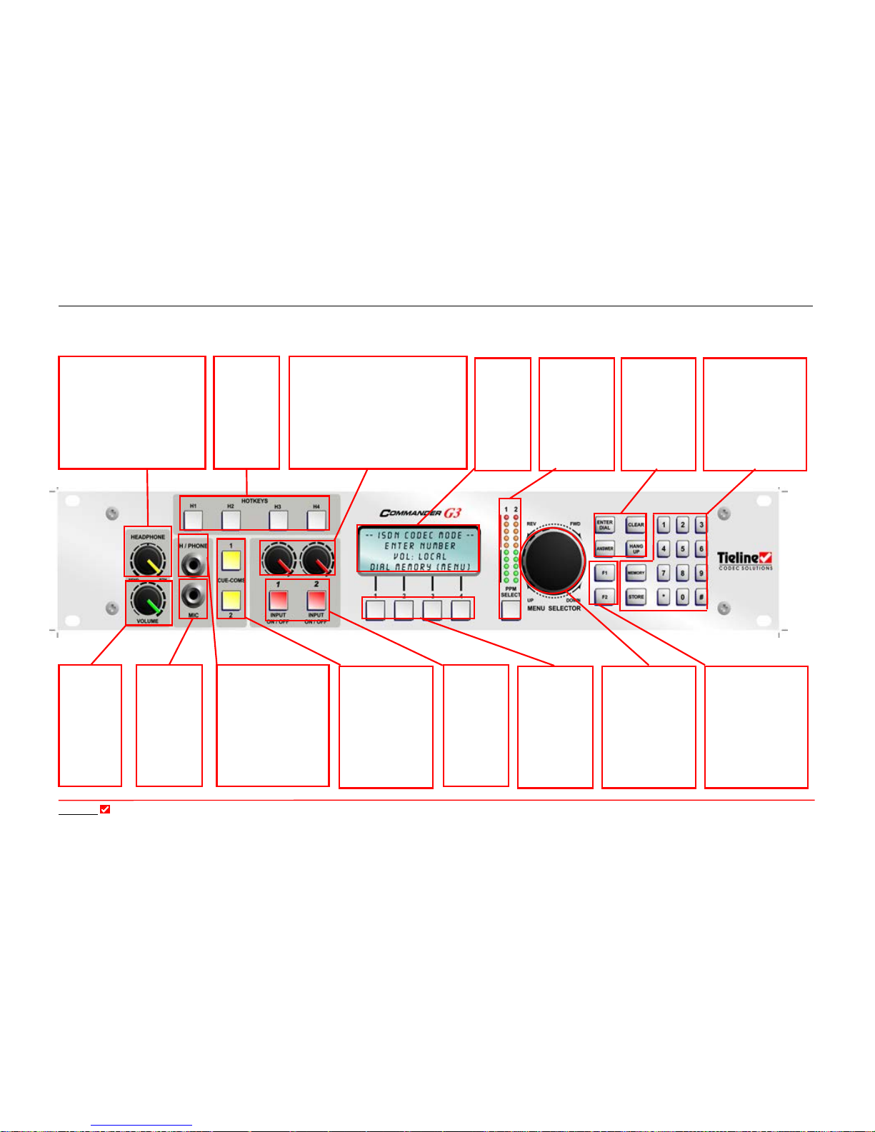
Section 7: Functionality of the Commander G3 Rack Unit
Tieline
Page 30
T E C H N O L O G Y
HEADPHONE or
MONO OUTPUT
Industry Standard 1/4”
(6.5mm) headphone
output, p
rogrammable
with ToolBox software.
Can also be
programmed to be a
balanced mono output.
Figure 1: 2RU Front Panel for the Commander G3 Rack Unit Codec
MENU
SELECTOR (MS)
For navigation
through the menu
options. Pressing
the MS down
selects the
bracketed option.
LCD
DISPLAY
4 rows of
20
characters
display the
menu
options.
ENTER/DIAL
CLEAR
ANSWER
HANG UP
POTS/ISDN/
GSM/X.21/IP
phone function
buttons.
KEYPAD
MEMORY & STORE
For dialing numbers.
Memory and store
are for storing &
accessing numbers in
the 50 entry phone
book.
FUNCTIONS
BUTTONS
Used for initiating
User Functions.
These can all be
programmed with
ToolBox within the
Functions
menu in
the
Profile Editor
.
SOFTKEYS
Programmable
buttons for one
press
initialization of
User
Functions.
CHANNEL
ON/OFF
Illuminated
red when
channel is
active.
INPUT
Trims the input gain of that
channel.
Menu items select between:
+15 dBu line level input
+35 dBu unbalanced
+55 dBu mic input
+65 dBu mic input
+72 dBu
mic input
VOLUME
Sets the
volume in
the
headphones
BALANCE
Controls the balance between
the SEND & RETURN
audio
to the headphones. This
control does not affect the level
of the transmitted or received
program audio. It only
controls the monitoring.
CUE-COMMS
Pressing this button
causes the codec to
adopt the switching
rules in the
Tool
Box Matrix
routing rules.
HOTKEYS
Programm-
able buttons
for one press
initialization
of functions
preset with
ToolBox.
MIC IN
Mic or
line level
input on
Industry
Standard
¼”
, 6.5mm
connector
PPM style
meter
.
10 LEDs in
3dB
increments.
Programmable
for send or
receive audio.
 Loading...