

Tieline Bridge-IT XTRA User Manual
Bridge-IT XTRA
IP Codec User Manual
Software Version: 2.14.88
Manual Version: v.2.2_20151125
November, 2015

Bridge-IT X TRA Ma nual2
© Tieline Pty. Lt d. 2015
Table of Contents
Part I How to Use the Documentation
5
Part II W arnings and Safety Informati on
6
Part III Glossary of Terms
11
Part IV Introduction to Bridge-IT XTRA
13
Part V XTRA Front Panel Controls
14
Part VI XTRA Rear Panel Connections
16
Part VII Navigating Codec Menus
17
Part VIII A djusting Input/Meter Levels
22
Part IX Configuring AES3 Audio
26
Part X Headphone/Output Monitoring
28
Part XI Language Selecti on
29
Part XII About Program Dialing
30
Part XIII Getting Connected Quickly
32
... . . . . . . . . . . . . . . . . . . . . . . . . . . . . . . . . . . . . . . . . .... . . . . . . . . . . . . . . . . . . . . . . . . . . . . . . . . . . . . . . . . . . .... . . . . . . . . . . . . . . . . . . . . . . . . . . . . . . . . . . . . . . 321 10 Quick Steps to Connect Bridge-IT
... . . . . . . . . . . . . . . . . . . . . . . . . . . . . . . . . . . . . . . . . .... . . . . . . . . . . . . . . . . . . . . . . . . . . . . . . . . . . . . . . . . . . .... . . . . . . . . . . . . . . . . . . . . . . . . . . . . . . . . . . . . . . 352 Monitoring IP Connections
... . . . . . . . . . . . . . . . . . . . . . . . . . . . . . . . . . . . . . . . . .... . . . . . . . . . . . . . . . . . . . . . . . . . . . . . . . . . . . . . . . . . . .... . . . . . . . . . . . . . . . . . . . . . . . . . . . . . . . . . . . . . . 373 Load and Dial Cus t om Programs
... . . . . . . . . . . . . . . . . . . . . . . . . . . . . . . . . . . . . . . . . .... . . . . . . . . . . . . . . . . . . . . . . . . . . . . . . . . . . . . . . . . . . .... . . . . . . . . . . . . . . . . . . . . . . . . . . . . . . . . . . . . . . 374 Disc onnecting a Connection
... . . . . . . . . . . . . . . . . . . . . . . . . . . . . . . . . . . . . . . . . .... . . . . . . . . . . . . . . . . . . . . . . . . . . . . . . . . . . . . . . . . . . .... . . . . . . . . . . . . . . . . . . . . . . . . . . . . . . . . . . . . . . 385 Redialing a Connection
... . . . . . . . . . . . . . . . . . . . . . . . . . . . . . . . . . . . . . . . . .... . . . . . . . . . . . . . . . . . . . . . . . . . . . . . . . . . . . . . . . . . . .... . . . . . . . . . . . . . . . . . . . . . . . . . . . . . . . . . . . . . . 386 Configuring Auto Reconnect
... . . . . . . . . . . . . . . . . . . . . . . . . . . . . . . . . . . . . . . . . .... . . . . . . . . . . . . . . . . . . . . . . . . . . . . . . . . . . . . . . . . . . .... . . . . . . . . . . . . . . . . . . . . . . . . . . . . . . . . . . . . . . 397 Speed Dialing Connections
... . . . . . . . . . . . . . . . . . . . . . . . . . . . . . . . . . . . . . . . . .... . . . . . . . . . . . . . . . . . . . . . . . . . . . . . . . . . . . . . . . . . . .... . . . . . . . . . . . . . . . . . . . . . . . . . . . . . . . . . . . . . . 398 Dial/Disconnect Multiple Connections
... . . . . . . . . . . . . . . . . . . . . . . . . . . . . . . . . . . . . . . . . .... . . . . . . . . . . . . . . . . . . . . . . . . . . . . . . . . . . . . . . . . . . .... . . . . . . . . . . . . . . . . . . . . . . . . . . . . . . . . . . . . . . 409 Creating a Multicast Server Program
... . . . . . . . . . . . . . . . . . . . . . . . . . . . . . . . . . . . . . . . . .... . . . . . . . . . . . . . . . . . . . . . . . . . . . . . . . . . . . . . . . . . . .... . . . . . . . . . . . . . . . . . . . . . . . . . . . . . . . . . . . . . . 4310 Creating a Multicast Client Program
... . . . . . . . . . . . . . . . . . . . . . . . . . . . . . . . . . . . . . . . . .... . . . . . . . . . . . . . . . . . . . . . . . . . . . . . . . . . . . . . . . . . . .... . . . . . . . . . . . . . . . . . . . . . . . . . . . . . . . . . . . . . . 4511 Dialing SIP Peer-to-Peer
... . . . . . . . . . . . . . . . . . . . . . . . . . . . . . . . . . . . . . . . . .... . . . . . . . . . . . . . . . . . . . . . . . . . . . . . . . . . . . . . . . . . . .... . . . . . . . . . . . . . . . . . . . . . . . . . . . . . . . . . . . . . . 4612 Dialing SIP Addresses
... . . . . . . . . . . . . . . . . . . . . . . . . . . . . . . . . . . . . . . . . .... . . . . . . . . . . . . . . . . . . . . . . . . . . . . . . . . . . . . . . . . . . .... . . . . . . . . . . . . . . . . . . . . . . . . . . . . . . . . . . . . . . 4713 Deleting Programs
... . . . . . . . . . . . . . . . . . . . . . . . . . . . . . . . . . . . . . . . . .... . . . . . . . . . . . . . . . . . . . . . . . . . . . . . . . . . . . . . . . . . . .... . . . . . . . . . . . . . . . . . . . . . . . . . . . . . . . . . . . . . . 4714 Selecting Algorithm Profiles
... . . . . . . . . . . . . . . . . . . . . . . . . . . . . . . . . . . . . . . . . .... . . . . . . . . . . . . . . . . . . . . . . . . . . . . . . . . . . . . . . . . . . .... . . . . . . . . . . . . . . . . . . . . . . . . . . . . . . . . . . . . . . 5015 SDHC Card Backup
... . . . . . . . . . . . . . . . . . . . . . . . . . . . . . . . . . . . . . . . . .... . . . . . . . . . . . . . . . . . . . . . . . . . . . . . . . . . . . . . . . . . . .... . . . . . . . . . . . . . . . . . . . . . . . . . . . . . . . . . . . . . . 5016 SDHC Card File Playback
... . . . . . . . . . . . . . . . . . . . . . . . . . . . . . . . . . . . . . . . . .... . . . . . . . . . . . . . . . . . . . . . . . . . . . . . . . . . . . . . . . . . . .... . . . . . . . . . . . . . . . . . . . . . . . . . . . . . . . . . . . . . . 5117 Lock or Unlock a Program in the Codec
... . . . . . . . . . . . . . . . . . . . . . . . . . . . . . . . . . . . . . . . . .... . . . . . . . . . . . . . . . . . . . . . . . . . . . . . . . . . . . . . . . . . . .... . . . . . . . . . . . . . . . . . . . . . . . . . . . . . . . . . . . . . . 5218 Locking the Front Panel

3Contents
© Tieline Pty. Lt d. 2015
Part XIV Connecting to the ToolBox
Web-GUI
53
... . . . . . . . . . . . . . . . . . . . . . . . . . . . . . . . . . . . . . . . . .... . . . . . . . . . . . . . . . . . . . . . . . . . . . . . . . . . . . . . . . . . . .... . . . . . . . . . . . . . . . . . . . . . . . . . . . . . . . . . . . . . . 541 Opening the Java or HTML5 Web-GUI & Login
... . . . . . . . . . . . . . . . . . . . . . . . . . . . . . . . . . . . . . . . . .... . . . . . . . . . . . . . . . . . . . . . . . . . . . . . . . . . . . . . . . . . . .... . . . . . . . . . . . . . . . . . . . . . . . . . . . . . . . . . . . . . . 572 Changing the Default Pas sword
... . . . . . . . . . . . . . . . . . . . . . . . . . . . . . . . . . . . . . . . . .... . . . . . . . . . . . . . . . . . . . . . . . . . . . . . . . . . . . . . . . . . . .... . . . . . . . . . . . . . . . . . . . . . . . . . . . . . . . . . . . . . . 583 Installing USB Drivers
... . . . . . . . . . . . . . . . . . . . . . . . . . . . . . . . . . . . . . . . . .... . . . . . . . . . . . . . . . . . . . . . . . . . . . . . . . . . . . . . . . . . . .... . . . . . . . . . . . . . . . . . . . . . . . . . . . . . . . . . . . . . . 594 Launching the GUI over USB
Part XV Java Toolbox Web-GUI
Introduction
59
Part XVI Java Toolbox Web-GUI Codec
Configuration
67
... . . . . . . . . . . . . . . . . . . . . . . . . . . . . . . . . . . . . . . . . .... . . . . . . . . . . . . . . . . . . . . . . . . . . . . . . . . . . . . . . . . . . .... . . . . . . . . . . . . . . . . . . . . . . . . . . . . . . . . . . . . . . 671 Configuring IP Settings
... . . . . . . . . . . . . . . . . . . . . . . . . . . . . . . . . . . . . . . . . .... . . . . . . . . . . . . . . . . . . . . . . . . . . . . . . . . . . . . . . . . . . .... . . . . . . . . . . . . . . . . . . . . . . . . . . . . . . . . . . . . . . 722 Configuring Input/Output Settings
... . . . . . . . . . . . . . . . . . . . . . . . . . . . . . . . . . . . . . . . . .... . . . . . . . . . . . . . . . . . . . . . . . . . . . . . . . . . . . . . . . . . . .... . . . . . . . . . . . . . . . . . . . . . . . . . . . . . . . . . . . . . . 763 Configuring Mono or Stereo Peer-to-Peer Programs
... . . . . . . . . . . . . . . . . . . . . . . . . . . . . . . . . . . . . . . . . .... . . . . . . . . . . . . . . . . . . . . . . . . . . . . . . . . . . . . . . . . . . .... . . . . . . . . . . . . . . . . . . . . . . . . . . . . . . . . . . . . . . 824 Configuring Multi-U nicast Dialing Programs
... . . . . . . . . . . . . . . . . . . . . . . . . . . . . . . . . . . . . . . . . .... . . . . . . . . . . . . . . . . . . . . . . . . . . . . . . . . . . . . . . . . . . .... . . . . . . . . . . . . . . . . . . . . . . . . . . . . . . . . . . . . . . 875 Configuring Multicas t Server Programs
... . . . . . . . . . . . . . . . . . . . . . . . . . . . . . . . . . . . . . . . . .... . . . . . . . . . . . . . . . . . . . . . . . . . . . . . . . . . . . . . . . . . . .... . . . . . . . . . . . . . . . . . . . . . . . . . . . . . . . . . . . . . . 916 Configuring Multicas t Client Programs
... . . . . . . . . . . . . . . . . . . . . . . . . . . . . . . . . . . . . . . . . .... . . . . . . . . . . . . . . . . . . . . . . . . . . . . . . . . . . . . . . . . . . .... . . . . . . . . . . . . . . . . . . . . . . . . . . . . . . . . . . . . . . 947 Configuring SIP Settings
... . . . . . . . . . . . . . . . . . . . . . . . . . . . . . . . . . . . . . . . . .... . . . . . . . . . . . . . . . . . . . . . . . . . . . . . . . . . . . . . . . . . . .... . . . . . . . . . . . . . . . . . . . . . . . . . . . . . . . . . . . . . . 968 Configuring SIP Programs
... . . . . . . . . . . . . . . . . . . . . . . . . . . . . . . . . . . . . . . . . .... . . . . . . . . . . . . . . . . . . . . . . . . . . . . . . . . . . . . . . . . . . .... . . . . . . . . . . . . . . . . . . . . . . . . . . . . . . . . . . . . . . 1009 Dial and Disconnect a Program
... . . . . . . . . . . . . . . . . . . . . . . . . . . . . . . . . . . . . . . . . .... . . . . . . . . . . . . . . . . . . . . . . . . . . . . . . . . . . . . . . . . . . .... . . . . . . . . . . . . . . . . . . . . . . . . . . . . . . . . . . . . . . 10110 Dial and Disconnect Multi-unicast Connections
... . . . . . . . . . . . . . . . . . . . . . . . . . . . . . . . . . . . . . . . . .... . . . . . . . . . . . . . . . . . . . . . . . . . . . . . . . . . . . . . . . . . . .... . . . . . . . . . . . . . . . . . . . . . . . . . . . . . . . . . . . . . . 10311 Lock or Unlock Programs
... . . . . . . . . . . . . . . . . . . . . . . . . . . . . . . . . . . . . . . . . .... . . . . . . . . . . . . . . . . . . . . . . . . . . . . . . . . . . . . . . . . . . .... . . . . . . . . . . . . . . . . . . . . . . . . . . . . . . . . . . . . . . 10312 View/Edit/Delete Programs
... . . . . . . . . . . . . . . . . . . . . . . . . . . . . . . . . . . . . . . . . .... . . . . . . . . . . . . . . . . . . . . . . . . . . . . . . . . . . . . . . . . . . .... . . . . . . . . . . . . . . . . . . . . . . . . . . . . . . . . . . . . . . 10613 Res et Factory Default Settings
... . . . . . . . . . . . . . . . . . . . . . . . . . . . . . . . . . . . . . . . . .... . . . . . . . . . . . . . . . . . . . . . . . . . . . . . . . . . . . . . . . . . . .... . . . . . . . . . . . . . . . . . . . . . . . . . . . . . . . . . . . . . . 10714 Backup and Rest ore Functions
... . . . . . . . . . . . . . . . . . . . . . . . . . . . . . . . . . . . . . . . . .... . . . . . . . . . . . . . . . . . . . . . . . . . . . . . . . . . . . . . . . . . . .... . . . . . . . . . . . . . . . . . . . . . . . . . . . . . . . . . . . . . . 10915 Web-GUI Soft ware Licens e Ins tallation
... . . . . . . . . . . . . . . . . . . . . . . . . . . . . . . . . . . . . . . . . .... . . . . . . . . . . . . . . . . . . . . . . . . . . . . . . . . . . . . . . . . . . .... . . . . . . . . . . . . . . . . . . . . . . . . . . . . . . . . . . . . . . 11016 Download Logs
... . . . . . . . . . . . . . . . . . . . . . . . . . . . . . . . . . . . . . . . . .... . . . . . . . . . . . . . . . . . . . . . . . . . . . . . . . . . . . . . . . . . . .... . . . . . . . . . . . . . . . . . . . . . . . . . . . . . . . . . . . . . . 11117 RS232 Data Configuration
... . . . . . . . . . . . . . . . . . . . . . . . . . . . . . . . . . . . . . . . . .... . . . . . . . . . . . . . . . . . . . . . . . . . . . . . . . . . . . . . . . . . . .... . . . . . . . . . . . . . . . . . . . . . . . . . . . . . . . . . . . . . . 11218 Creating Rules
... . . . . . . . . . . . . . . . . . . . . . . . . . . . . . . . . . . . . . . . . .... . . . . . . . . . . . . . . . . . . . . . . . . . . . . . . . . . . . . . . . . . . .... . . . . . . . . . . . . . . . . . . . . . . . . . . . . . . . . . . . . . . 11619 Upgrading Codec Firmware
Part XVII HTML5 Toolbox Web-GUI
Introduction
118
Part XVIII HTML5 Toolbox Web-GUI
Configuration
129
... . . . . . . . . . . . . . . . . . . . . . . . . . . . . . . . . . . . . . . . . .... . . . . . . . . . . . . . . . . . . . . . . . . . . . . . . . . . . . . . . . . . . .... . . . . . . . . . . . . . . . . . . . . . . . . . . . . . . . . . . . . . . 1291 Using the HTML5 Toolbox Quick Connect Web-GUI
... . . . . . . . . . . . . . . . . . . . . . . . . . . . . . . . . . . . . . . . . .... . . . . . . . . . . . . . . . . . . . . . . . . . . . . . . . . . . . . . . . . . . .... . . . . . . . . . . . . . . . . . . . . . . . . . . . . . . . . . . . . . . 1342 Configuring IP Settings
... . . . . . . . . . . . . . . . . . . . . . . . . . . . . . . . . . . . . . . . . .... . . . . . . . . . . . . . . . . . . . . . . . . . . . . . . . . . . . . . . . . . . .... . . . . . . . . . . . . . . . . . . . . . . . . . . . . . . . . . . . . . . 1383 Configuring Input/Output Settings
... . . . . . . . . . . . . . . . . . . . . . . . . . . . . . . . . . . . . . . . . .... . . . . . . . . . . . . . . . . . . . . . . . . . . . . . . . . . . . . . . . . . . .... . . . . . . . . . . . . . . . . . . . . . . . . . . . . . . . . . . . . . . 1404 Configure SIP Settings
... . . . . . . . . . . . . . . . . . . . . . . . . . . . . . . . . . . . . . . . . .... . . . . . . . . . . . . . . . . . . . . . . . . . . . . . . . . . . . . . . . . . . .... . . . . . . . . . . . . . . . . . . . . . . . . . . . . . . . . . . . . . . 1435 Load, Unload and Dial a Program
... . . . . . . . . . . . . . . . . . . . . . . . . . . . . . . . . . . . . . . . . .... . . . . . . . . . . . . . . . . . . . . . . . . . . . . . . . . . . . . . . . . . . .... . . . . . . . . . . . . . . . . . . . . . . . . . . . . . . . . . . . . . . 1466 Lock or Unlock Programs

Bridge-IT X TRA Ma nual4
© Tieline Pty. Lt d. 2015
... . . . . . . . . . . . . . . . . . . . . . . . . . . . . . . . . . . . . . . . . .... . . . . . . . . . . . . . . . . . . . . . . . . . . . . . . . . . . . . . . . . . . .... . . . . . . . . . . . . . . . . . . . . . . . . . . . . . . . . . . . . . . 1477 Reset Factory Default Settings
... . . . . . . . . . . . . . . . . . . . . . . . . . . . . . . . . . . . . . . . . .... . . . . . . . . . . . . . . . . . . . . . . . . . . . . . . . . . . . . . . . . . . .... . . . . . . . . . . . . . . . . . . . . . . . . . . . . . . . . . . . . . . 1488 Backup and Restore Functions
... . . . . . . . . . . . . . . . . . . . . . . . . . . . . . . . . . . . . . . . . .... . . . . . . . . . . . . . . . . . . . . . . . . . . . . . . . . . . . . . . . . . . .... . . . . . . . . . . . . . . . . . . . . . . . . . . . . . . . . . . . . . . 1499 HTML5 Software License Inst allation
... . . . . . . . . . . . . . . . . . . . . . . . . . . . . . . . . . . . . . . . . .... . . . . . . . . . . . . . . . . . . . . . . . . . . . . . . . . . . . . . . . . . . .... . . . . . . . . . . . . . . . . . . . . . . . . . . . . . . . . . . . . . . 15010 Download Logs
... . . . . . . . . . . . . . . . . . . . . . . . . . . . . . . . . . . . . . . . . .... . . . . . . . . . . . . . . . . . . . . . . . . . . . . . . . . . . . . . . . . . . .... . . . . . . . . . . . . . . . . . . . . . . . . . . . . . . . . . . . . . . 15111 RS232 Data Configuration
... . . . . . . . . . . . . . . . . . . . . . . . . . . . . . . . . . . . . . . . . .... . . . . . . . . . . . . . . . . . . . . . . . . . . . . . . . . . . . . . . . . . . .... . . . . . . . . . . . . . . . . . . . . . . . . . . . . . . . . . . . . . . 15312 Creating Rules
... . . . . . . . . . . . . . . . . . . . . . . . . . . . . . . . . . . . . . . . . .... . . . . . . . . . . . . . . . . . . . . . . . . . . . . . . . . . . . . . . . . . . .... . . . . . . . . . . . . . . . . . . . . . . . . . . . . . . . . . . . . . . 15713 Upgrading Codec Firmware
Part XIX Front Panel Configuration Tasks
158
... . . . . . . . . . . . . . . . . . . . . . . . . . . . . . . . . . . . . . . . . .... . . . . . . . . . . . . . . . . . . . . . . . . . . . . . . . . . . . . . . . . . . .... . . . . . . . . . . . . . . . . . . . . . . . . . . . . . . . . . . . . . . 1581 Configuring IP via the Front Panel
... . . . . . . . . . . . . . . . . . . . . . . . . . . . . . . . . . . . . . . . . .... . . . . . . . . . . . . . . . . . . . . . . . . . . . . . . . . . . . . . . . . . . .... . . . . . . . . . . . . . . . . . . . . . . . . . . . . . . . . . . . . . . 1612 Selecting an Algorithm
... . . . . . . . . . . . . . . . . . . . . . . . . . . . . . . . . . . . . . . . . .... . . . . . . . . . . . . . . . . . . . . . . . . . . . . . . . . . . . . . . . . . . .... . . . . . . . . . . . . . . . . . . . . . . . . . . . . . . . . . . . . . . 1673 Configuring the Jitter Buffer
... . . . . . . . . . . . . . . . . . . . . . . . . . . . . . . . . . . . . . . . . .... . . . . . . . . . . . . . . . . . . . . . . . . . . . . . . . . . . . . . . . . . . .... . . . . . . . . . . . . . . . . . . . . . . . . . . . . . . . . . . . . . . 1704 Configuring Forward Error Correction
... . . . . . . . . . . . . . . . . . . . . . . . . . . . . . . . . . . . . . . . . .... . . . . . . . . . . . . . . . . . . . . . . . . . . . . . . . . . . . . . . . . . . .... . . . . . . . . . . . . . . . . . . . . . . . . . . . . . . . . . . . . . . 1725 Configuring Encode/Decode Direction
... . . . . . . . . . . . . . . . . . . . . . . . . . . . . . . . . . . . . . . . . .... . . . . . . . . . . . . . . . . . . . . . . . . . . . . . . . . . . . . . . . . . . .... . . . . . . . . . . . . . . . . . . . . . . . . . . . . . . . . . . . . . . 1726 Bridge-IT XTRA Relays and RS232 Data
... . . . . . . . . . . . . . . . . . . . . . . . . . . . . . . . . . . . . . . . . .... . . . . . . . . . . . . . . . . . . . . . . . . . . . . . . . . . . . . . . . . . . .... . . . . . . . . . . . . . . . . . . . . . . . . . . . . . . . . . . . . . . 1747 Configuring TCP/UDP Ports
... . . . . . . . . . . . . . . . . . . . . . . . . . . . . . . . . . . . . . . . . .... . . . . . . . . . . . . . . . . . . . . . . . . . . . . . . . . . . . . . . . . . . .... . . . . . . . . . . . . . . . . . . . . . . . . . . . . . . . . . . . . . . 1768 Configuring QoS for Broadcast s
... . . . . . . . . . . . . . . . . . . . . . . . . . . . . . . . . . . . . . . . . .... . . . . . . . . . . . . . . . . . . . . . . . . . . . . . . . . . . . . . . . . . . .... . . . . . . . . . . . . . . . . . . . . . . . . . . . . . . . . . . . . . . 1779 Configuring Data Packet Time-to-Live
... . . . . . . . . . . . . . . . . . . . . . . . . . . . . . . . . . . . . . . . . .... . . . . . . . . . . . . . . . . . . . . . . . . . . . . . . . . . . . . . . . . . . .... . . . . . . . . . . . . . . . . . . . . . . . . . . . . . . . . . . . . . . 17810 Res et and Restore Factory Default Settings
... . . . . . . . . . . . . . . . . . . . . . . . . . . . . . . . . . . . . . . . . .... . . . . . . . . . . . . . . . . . . . . . . . . . . . . . . . . . . . . . . . . . . .... . . . . . . . . . . . . . . . . . . . . . . . . . . . . . . . . . . . . . . 17811 Inst alling Software Licences
Part XX Reference
180
... . . . . . . . . . . . . . . . . . . . . . . . . . . . . . . . . . . . . . . . . .... . . . . . . . . . . . . . . . . . . . . . . . . . . . . . . . . . . . . . . . . . . .... . . . . . . . . . . . . . . . . . . . . . . . . . . . . . . . . . . . . . . 1801 Regular Maintenance
... . . . . . . . . . . . . . . . . . . . . . . . . . . . . . . . . . . . . . . . . .... . . . . . . . . . . . . . . . . . . . . . . . . . . . . . . . . . . . . . . . . . . .... . . . . . . . . . . . . . . . . . . . . . . . . . . . . . . . . . . . . . . 1812 Inst alling the Codec at the Studio
... . . . . . . . . . . . . . . . . . . . . . . . . . . . . . . . . . . . . . . . . .... . . . . . . . . . . . . . . . . . . . . . . . . . . . . . . . . . . . . . . . . . . .... . . . . . . . . . . . . . . . . . . . . . . . . . . . . . . . . . . . . . . 1873 Underst anding IP Networks
... . . . . . . . . . . . . . . . . . . . . . . . . . . . . . . . . . . . . . . . . .... . . . . . . . . . . . . . . . . . . . . . . . . . . . . . . . . . . . . . . . . . . .... . . . . . . . . . . . . . . . . . . . . . . . . . . . . . . . . . . . . . . 1894 Tips for Creating Reliable IP Connections
... . . . . . . . . . . . . . . . . . . . . . . . . . . . . . . . . . . . . . . . . .... . . . . . . . . . . . . . . . . . . . . . . . . . . . . . . . . . . . . . . . . . . .... . . . . . . . . . . . . . . . . . . . . . . . . . . . . . . . . . . . . . . 1905 Testing IP Network Connections
... . . . . . . . . . . . . . . . . . . . . . . . . . . . . . . . . . . . . . . . . .... . . . . . . . . . . . . . . . . . . . . . . . . . . . . . . . . . . . . . . . . . . .... . . . . . . . . . . . . . . . . . . . . . . . . . . . . . . . . . . . . . . 1926 Software Licences
... . . . . . . . . . . . . . . . . . . . . . . . . . . . . . . . . . . . . . . . . .... . . . . . . . . . . . . . . . . . . . . . . . . . . . . . . . . . . . . . . . . . . .... . . . . . . . . . . . . . . . . . . . . . . . . . . . . . . . . . . . . . . 2007 Compliances and Certifications
... . . . . . . . . . . . . . . . . . . . . . . . . . . . . . . . . . . . . . . . . .... . . . . . . . . . . . . . . . . . . . . . . . . . . . . . . . . . . . . . . . . . . .... . . . . . . . . . . . . . . . . . . . . . . . . . . . . . . . . . . . . . . 2028 Trademarks and Credit Not ices
Part XXI Bridge-IT XTRA Specifications
203
Index 204
5
© Tieline Pty. Lt d. 2015
Bridge-IT X TRA Ma nual
1 How to Use the Documentation
Overview of this User Manual
Use this manual to learn how to:
· Connect the codec to an IP network and configure peer-to-peer, multicast or multi-unicast
connections.
· Configure the codec over a LAN or USB cable.
· Adjust audio and other settings within the codec.
· Configure automatic SDHC card backup.
Please read Getting Connected Quickly for an overview of how to configure the codec using
'programs' to store connection settings.
Manual Conventi ons
Warnings: Instructions t hat, if ignored, c ould result in death or serious personal injury
caused by incorrect operation of the equipment. These must be observed for safe operation.
Cautions: Ins t ruct ions warning against potential hazards, or to detail practices t hat mus t be
observed for safe operation and to prevent damage to equipment or personnel.
Importa n t Note: Information you should know to connect and operate your codec
successfully.
Typographic Conventions
· Codec software elements are in Arial bold, e.g. Contacts
· Codec hardware elements are in bold Capitals, e.g. KEYPAD
Help Butt on
Press the (information/help) button on the codec when navigating codec menus to display a
help dialog on the LCD screen suggesting actions which can be performed from the current menu
item.

6 Bridge-IT X TRA Ma nual
© Tieline Pty. Lt d. 2015
2 Warnings and Safety Info rm ation
THUNDERSTORM AND LIGHTNING WARNING:
DO NOT USE Tieline codecs during thunderstorms and lightning. You may suffer an injury
using a Tieline codec, or any device connected to a LAN connection during a thunderstorm.
This can lead to personal injury and in extreme cases may be fatal. Protective devices can
be fitted to lines, however, due to the extremely high voltages and energy levels involved in
lightning strikes, these devices may not offer protection to users, the Tieline codec and
equipment connected to the codec.
Secondary strikes can occur. These secondary strikes are induced by lightning strikes and
also produce dangerously high currents and energy levels. You only need to be near an
object struck by lightning to lead to personal injury or damage to equipment. e.g. if located
near a lighting tower at a sports facility, water features and drains on golf courses you may
be affected by these secondary strikes.
Damage to personnel and Tieline codecs may occur during thunderstorm, even if the codec
is turned off but is connected to the system or the power.
ANY DAMAGE TO A TIELINE PRODUCT CAUSED BY LIGHTNING or an ELECTRICAL
STORM WILL VOID THE WARRANTY. Use of this product is subject to Tieline's
SOFTWARE LICENSE and WARRANTY conditions, which should be viewed at
www.tieline.com/support before using this product.
SAFETY PRECAUTIONS:
· A readily accessible disconnect device shall be incorporated in the building installation
wiring.
· Due to the risks of electrical shock, and energy, mechanical, and fire hazards, any
procedures that involve opening panels or changing components must be performed by
qualified service personnel only.
· To reduce the risk of fire and electrical shock, disconnect the device from the power line
before removing the cover or panels.
· This unit has more than one power supply. Disconnect all power supplies before opening
to avoid electric shock. Disconnecting one power supply disconnects only one power
supply module. To isolate the unit completely, disconnect all power supplies.
SERVICING WARNINGS:
· Do not perform any servicing other than that contained in the operating instructions unless
you are qualified to do so.
· All work should be carried out by suitably qualified personnel.
· This unit has more than one power supply. Disconnect all power cables before
maintenance to avoid electric shock.
HIGH VOLTAGE WARNINGS:
· Any adjustment, maintenance, and repair of the opened instrument under voltage must be
avoided as much as possible and, when inevitable, must be carried out only by a skilled
person who is aware of the hazard involved.
· Capacitors inside the instrument may still be charged even if the instrument has been
disconnected from its source of supply.
GROUNDING:
Before connecting this device to the power line, where required, the protective earth terminal
screws of this device must be connected to the protective earth in the building installation.
LINE VOLTAGE:
Before connecting this device to the power line, make sure the voltage of the power source
7
© Tieline Pty. Lt d. 2015
Bridge-IT X TRA Ma nual
matches the requirements of the device. Refer to the device Specifications for information
about the correct power rating for the device.
FUSES:
Make sure that only fuses with the required rated current and of the specified type are used
for replacement. The use of repaired fuses and the short-circuiting of fuse holders must be
avoided. Whenever it is likely that the protection offered by fuses has been impaired, the
instrument must be made inoperative and be secured against any unintended operation.
WARNING:
HIGH LEAKAGE CURRENT. EARTH CONNECTION ESSENTIAL BEFORE CONNECTING
SUPPLY.
If the total leakage current exceeds 3.5 mA, or if the leakage current of the connected
loads is unknown, connect the supplementary ground terminal to a reliable ground
connection in your facility.
SUPPLEMENTARY GROUND CONNECTION:
A supplementary ground terminal is provided on the codec to connect the unit to a ground
connection. The ground terminal has an M4 stud with M4 retaining nuts and is compatible
with all grounding wires. Remove only the outer NUT to connect your ground wire. The
ground wire must have a suitable lug. When refitting the outer NUT ensure that both NUTS
are correctly tightened to establish and maintain a proper earth connection.
WARNING: To Reduce the Risk of Electrical Shock and Fire
1. This equipment is designed to permit connection between the earthed conductor of the
DC supply circuit and the earthing conductor equipment.
2. Equipment connected to the protective earthing of the building installation through the
mains connection or through other equipment with a connection to protective earthing and to a cable distribution system using coaxial cable, may in some circumstances
create a fire hazard. Connection to a cable distribution system must therefore be
provided through a device providing electrical isolation below a certain frequency range
(galvanic isolator, see EN 60728-11).
3. All servicing must be undertaken only by qualified service personnel. There are not user
serviceable parts inside the unit.
4. DO NOT plug in, turn on or attempt to operate an obviously damaged unit.
5. Ensure that the chassis ventilation openings in the unit are NOT BLOCKED.
6. Do not operate the device in a location where the maximum ambient temperature
exceeds 50°C (122°F), or is below 0°C (32°F).
7. Be sure to unplug both power supply cords from the wall socket BEFORE attempting to
service the power supply fuse.
AC units for Denmark, Finland, Norway, Sweden (marked on product):
• Denmark - “Unit is class I - unit to be used with an AC cord set suitable with Denmark
deviations. The cord includes an earthing conductor. The Unit is to be plugged into a wall
socket outlet which is connected to a protective earth. Socket outlets which are not
connected to earth are not to be used!”
• Finland - “Laite on liitettävä suojamaadoituskoskettimilla varustettuun pistorasiaan”
• Norway - “Apparatet må tilkoples jordet stikkontakt”
• Unit is intended for connection to IT power systems for Norway only.
• Sweden - “Apparaten skall anslutas till jordat uttag.”
To connect the power connection:
1. Connect the power cables to the power sockets, located on the rear panel of the device.
8 Bridge-IT X TRA Ma nual
© Tieline Pty. Lt d. 2015
2. Connect the power cables to the grounded AC outlets.
WARNING: Risk of electric shock and energy hazard. Disconnecting one power supply
disconnects only one power supply module. To isolate the unit completely, disconnect all
power supplies.
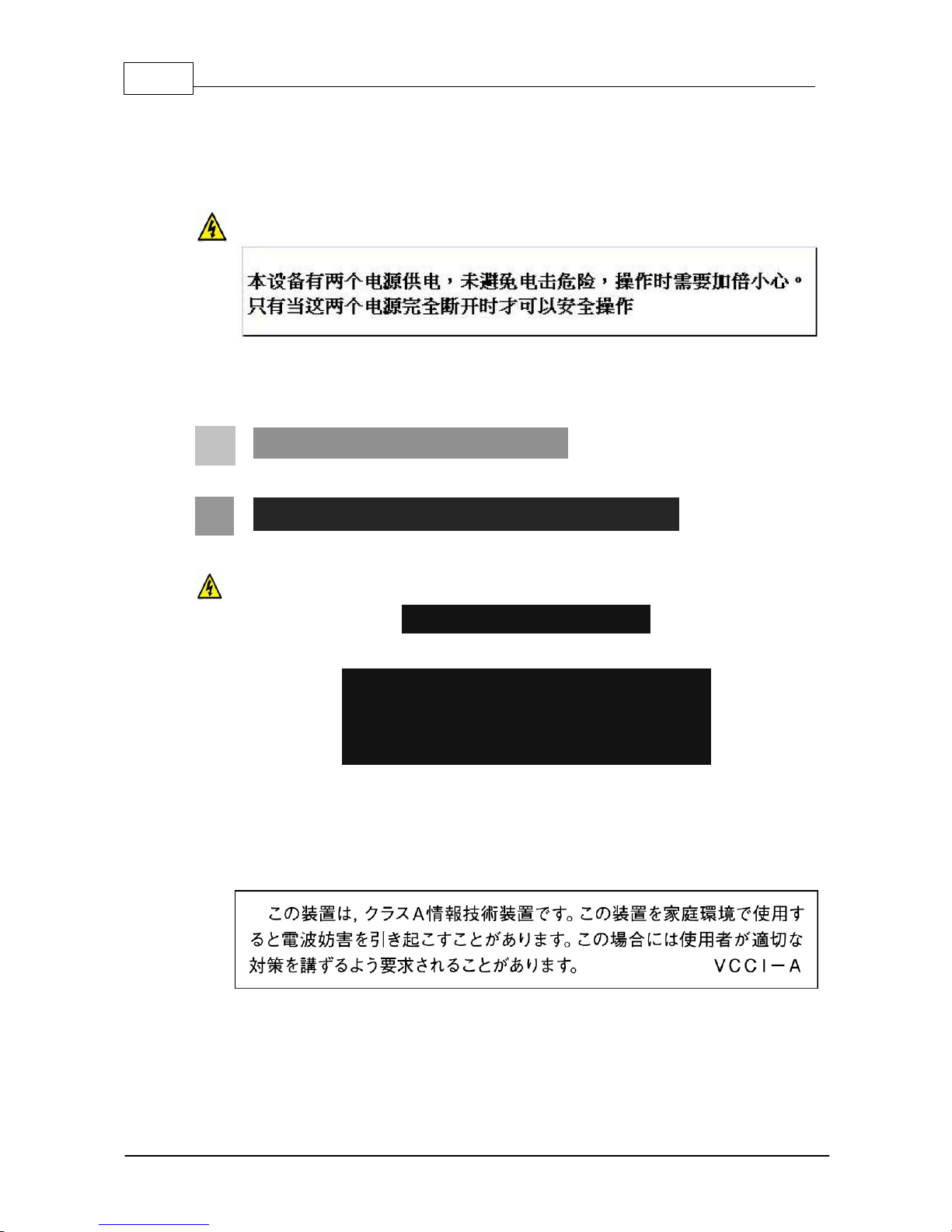
CHINESE SAFETY WARNINGS:
Translation of previous Chinese safety warning: This unit has two power supplies, please be
very careful when using, disconnect two power supplies before maintenance to avoid electric
shock.
This device must only be used in not-tropical climate regions.
This device must only be used at altit ude not exceeding 2000 metres.
JAPANESE SAFETY WARNINGS:
Translation of previous warning: Provide an earthing connection.
Translation of previous warning: Provide an earthing connection before the mains plug is
connected to the mains. And, when disconnecting the earthing connection, be sure to
disconnect after pulling out the mains plug from the mains.
Statement for Class A VCCI-certified Equipment:
Translation of previous Class A VCCI Statement: This is a Class A product based on the
standard of the Voluntary Control Council for Interference by Information Technology
Equipment (VCCI). If this equipment is used in a domestic environment, radio disturbance
may occur, in which case, the user may be required to take corrective action.
9
© Tieline Pty. Lt d. 2015
Bridge-IT X TRA Ma nual
Statement for Class B VCCI-certified Equipment:
Translation of previous Class B VCCI Statement: This is a Class B product based on the
standard of the Voluntary Control Council for Interference by Information Technology
Equipment (VCCI). If this is used near a radio or television receiver in a domestic
environment, it may cause radio interference. Install and use the equipment according to the
instruction manual.
Special Notices for North American Users:
For North American power connection, select a power supply cord that is UL Listed and
CSA Certified 3 - conductor, [18 AWG], terminated in a molded on plug cap rated 125 V, [5
A], with a minimum length of 1.5m [six feet] but no longer than 4.5m.
Special Notices for European Users:
For European connection, select a power supply cord that is internationally harmonized and
marked “<HAR>”, 3 - conductor, 0,75 mm2 minimum mm2 wire, rated 300 V, with a PVC
insulated jacket. The cord must have a molded on plug cap rated 250 V, 3 A.
Installation Codes:
This device must be installed according to country national electrical codes. For North
America, equipment must be installed in accordance with the US National Electrical Code,
Articles 110 - 16, 110 -17, and 110 -18 and the Canadian Electrical Code, Section 12.
Interconnection Cabling:
Cables for connecting to the unit's RS232 and Ethernet Interfaces must be UL certified type
DP-1 or DP-2. (Note: when residing in non-LPS circuit)
Overcurrent Protection:
A readily accessible listed branch-circuit over current protective device rated 15 A must be
incorporated in the building wiring for each power input.
Replaceable Batteries:
If equipment is provided with a replaceable battery, and is replaced by an incorrect battery
type, then an explosion may occur.
CAUTION: RISK OF EXPLOSION IF BATTERY IS REPLACED BY AN INCORRECT
BATTERY TYPE. DISPOSE OF USED BATTERIES ACCORDING TO THE INSTRUCTIONS.
This equipment is provided with a long life replaceable Panasonic CR2032 model 3V
manganese dioxide lithium coin battery. Service personnel should only replace this battery
with the same brand and type of battery. If this is replaced by an incorrect battery type, then
an explosion may occur. Visit http://www.panasonic.com/industrial/includes/pdf/
Panasonic_LithiumCR_Info.pdf to view the Material Safety Data Sheet for this battery.

10 Bridge-IT X TRA Ma nual
© Tieline Pty. Lt d. 2015
End of Life Statement
Tieline hereby declares that all materials, components and products supplied are in full compliance
with RoHS & WEE directives. This product must be disposed of according to local laws and
regulations. Because the product contains a battery it must be disposed of separately from
household waste. Do not incinerate, but take it to a recycling facility.
Disclaimer
Whilst every effort has been made to ensure the accuracy of this manual we are not responsible for
any errors or omissions within it. The product specifications and descriptions within this manual will
be subject to improvements and modifications over time without notice, as changes to software and
hardware are implemented.

11
© Tieline Pty. Lt d. 2015
Bridge-IT X TRA Ma nual
3 Glossary of Term s
AES/EBU
Digital audio standard used to carry digital audio signals between devices.
AES3
Official term for the audio standard referred to often as AES/EBU.
DNS
The Domain Name System (DNS) is used to assign domain names to IP
addresses over the World-Wide Web.
DSCP
The Differentiated Services Code Point is a field in an IP packet header for
prioritising data when traversing IP networks
Fail over
Method of switching to an alternative audio stream if the primary connection is
lost.
GUI
Acronym for Graphic User Interface
ISP
Internet Service Providers (ISPs) are companies that offer customers access to
the internet
IP
Internet Protocol; used for sending data across packet-switched networks.
LAN
Local Area Network; a group of computers and associated devices sharing a
common communications link
Latency
Delay associated with IP networks and caused by algorithmic, transport and
buffering delays.
Multicast
Efficient one to many streaming of IP audio using multicast IP addressing.
Multi-unicast
A multi-unicast program (also known as multiple unicast) can transmit a single
audio stream with common connection settings to a number of different
destinations.
Network Address
Translation
(NAT)
A system for forwarding data packets to different private IP network addresses
that reside behind a single public IP address.
Packet
A formatted unit of data carried over packet-switched networks.
Port Address
Translation
(PAT)
Related to NAT; a feature of a network device that allows IP packets to be
routed to specific ports of devices communicating between public and private IP
networks.
PSU
Power Supply Unit
QoS (Quality of
Service)
Priority given to different users or data flows across managed IP networks. This
generally requires a Service Level Agreement (SLA) with a Telco or ISP.
RTP
A standardized packet format for sending audio and video data streams and
ensures consistency in the delivery order of voice data packets.
SDP
SDP defines the type of audio coding used within an RTP media stream. It
works with a number of other protocols to establishes a device’s location,
determines its availability, negotiates call features and participants and adjusts
session management features.
SIP
SIP works with a myriad of other protocols to establish connections with other
devices. It is used to find call participants and devices and is the method used
by most broadcast codecs to connect to competing brands of codec for
interoperability.
SLA
Service Level Agreements (SLAs) a contractual agreement between an ISP and
a customer defining expected performance levels over a network
STL
Studio to transmitter link for program audio feeds.
TCP
TCP protocol ensures reliable in-order delivery of data packets between a
sender and a receiver. Its two functions include controlling the transmission
rate of data and ensuring reliable transmission occurs. Generally not wellsuited to streaming live audio because buffering (latency) is employed to
ensure data packets are received in order
TTL
Time-to-Live is the setting used in multicast servers to ensure data packets
have a finite life and don't cause congestion over networks.

12 Bridge-IT X TRA Ma nual
© Tieline Pty. Lt d. 2015
UDP
The protocol most commonly used for sending internet audio and video
streams. UDP packets include information which allows them to travel
independently of previous or future packets in a data stream. In general, UDP is
a much faster and more efficient method of sending audio over IP.
Unicast
Broadcasting of a single stream of data between two points.
WAN
Wide Area Network; a computer network spanning regions and/or countries to
connect separate LANs
13
© Tieline Pty. Lt d. 2015
Bridge-IT X TRA Ma nual
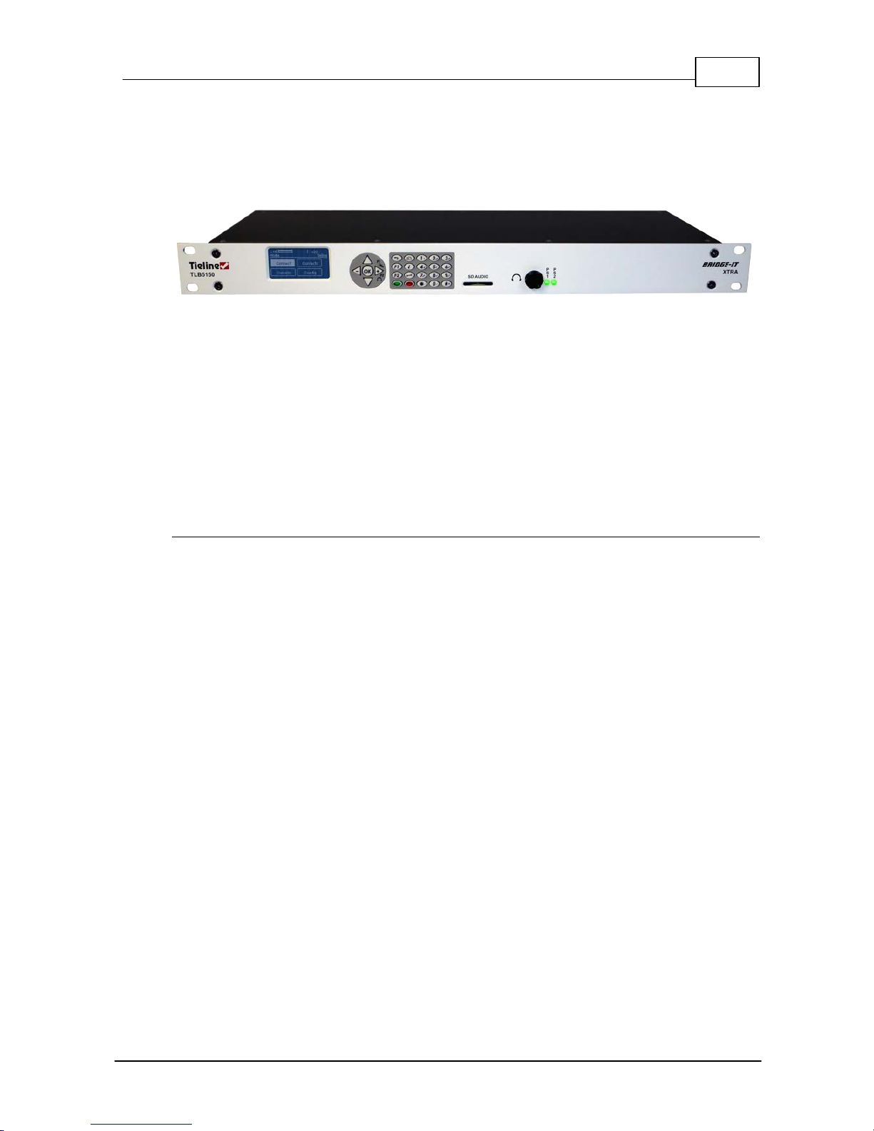
4 Introduction to Brid g e-IT XTRA
Tieline’s 1RU Bridge-IT XTRA is a cost effective, high-performance, peer-to-peer and multi-point
stereo IP audio codec with all the features of the Bridge-IT IP codec and more! Bridge-IT XTRA
includes additional features such as all algorithms as standard, dual internal power supplies, a front
panel stereo headphone output and 4 GPIO in/outs. It also includes SD/SDHC card audio backup.
Capable of both peer-to-peer or multi-point connections, the codec transports audio streams simply
and reliably over IP data networks such as wired and wireless LANs, WANs, the internet, satellite
IP, Wi-MAX and Wi-Fi.
Bridge-IT XTRA is perfect for a large range of broadcast and professional applications, including:
· Studio-to-Transmitter Link (STL) applications
· Studio-to-Studio Links
· IP Multi-unicasting (up to 6 endpoints)
· IP multicasting over compatible IP networks
· Simple remote broadcast links
Codec Features
· Suitable for peer-to-peer and multi-point IP connections over a variety of IP networks.
· Linear audio with suite of high quality broadcast algorithms as standard.
· The Opus algorithm and AAC-LD, AAC-ELD, LC-AAC, HE-AAC v.1 and HE-AAC v.2 as
standard.
· Tieline's loss-tolerant MusicPLUS algorithm provides up to 20 kHz stereo audio quality with
20ms coding delay at bit-rates as low as 96kbps - making it ideal for today's IP and 3G
networks.
· Tieline Music can deliver up to 15 kHz FM quality mono audio at bit-rates as low as 24Kbps,
with only 20 milliseconds encoding delay.
· SmartStream software for automatically managing jitter buffering, forward error correction and
packet repair.
· Hardware front panel interface including navigation buttons, LCD display, PPM metering and
dialing key pad.
· Web-GUI options for configuring codec functionality and RS232 data.
· Broadcast quality analog XLR inputs/outputs.
· XLR digital AES3 input/output.
· Simultaneous analog and digital AES3 audio outputs.
· Onboard SDHC card slot for automatic audio fail over.
· ¼” (6.35mm) stereo headphone output on front and rear panels.
· 4 relay inputs and 4 opto-isolated outputs plus RS-232 for local and remote control of
equipment at either end of your codec link.
· USB slave connection for codec configuration.
· Multilingual menus and web interface supported.
14 Bridge-IT X TRA Ma nual
© Tieline Pty. Lt d. 2015
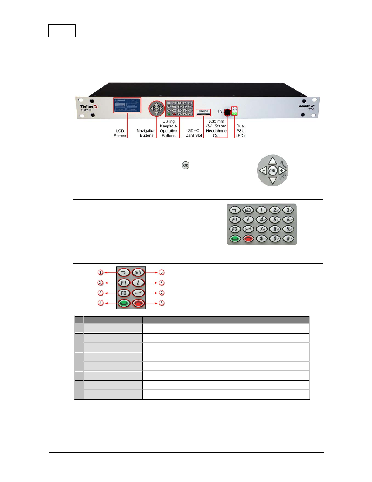
5 XTRA Front Pane l Controls
The Bridge-IT XTRA front panel features an LCD screen with PPM metering, menu navigation
buttons and a dialing keypad with operation buttons. The codec also features a stereo headphone
output and an SDHC card slot, which can be used for automatic audio backup.
Navigation Buttons
The codec has four arrow shaped navigation buttons for
navigating codec menus and an OK button for
selecting menu items.
Dialing Keypad
The keypad has alpha-numeric buttons and
operation buttons used to:
· Launch codec functions.
· Navigate menus.
· Dial and hang up connections.
· Configure contact details.
Operati on Button Descri pti ons
Features
Operation Button De scriptions
1
Return Button
Press to navigate back through menus & delete characters
2
Function Button 1
Press to open codec user functions
3
Function Button 2
Press to open codec user functions
4
Connect Button
Press to dial IP connections
5
Home Button
Press to return to home screen
6
Information Button
Press to view a help menu on-screen
7
Settings Button
Press to configure codec settings
8
Hangup Button
Press to end a call
15
© Tieline Pty. Lt d. 2015
Bridge-IT X TRA Ma nual
Adjusti ng LCD Screen Contrast Levels
1. Press and hold the button and then press the arrow up button to display the Contrast
adjustment screen.
2. Use the left and right arrow buttons to adjust the LCD screen contrast until viewing is
optimised.
3. Press when you have finished.
Contrast can also be adjusted by pressing the HOME button, selecting Settings, then System,
and using the down button to navigate to Contrast.
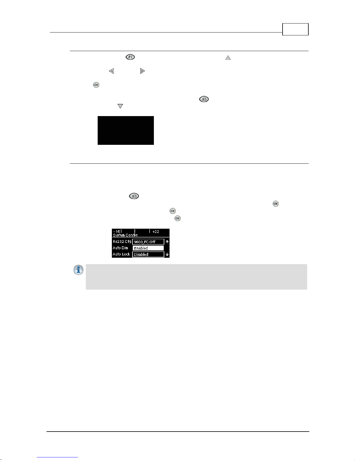
Enabling and Disabling LCD Screen Auto Dim M ode
By default the codec LCD screen has Auto Dim mode enabled. This dims the intensity of the
display 30 secs after inactivity and is designed to maximise the working life of the screen. Disable
this mode if you want the screen to be illuminated at all times.
1. Press the HOME button to return to the Home screen.
2. Use the navigation buttons on the front panel to select Settings and press the button.
3. Nav igate to System and press the button.
4. Nav igate to Auto Dim and press the button to toggle between Enabled and Disabled.
Importa n t Note: Th e default Auto Dim t ime-out is reduced from 30 seconds to 10 seconds
when the Auto Lock function is enabled (to lock the front panel controls). Disabling Auto
Dim mode will override all ti me-out periods and the LCD will remain fully ill uminated at all
times.
16 Bridge-IT X TRA Ma nual
© Tieline Pty. Lt d. 2015
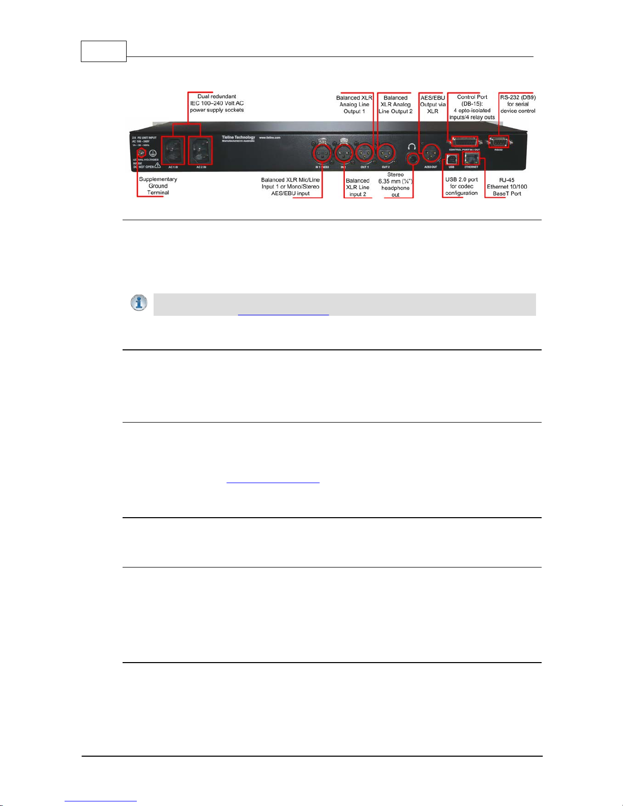
6 XTRA Rear Panel Connec tions
XLR Anal og and Digital I nputs
The codec features two XLR microphone inputs. Input 1 is a balanced mic/line input with the ability
to connect high, medium and low gain mics, as well as an unbalanced source. It has switchable
phantom power of 15 volts that is turned off by default and can also be used as an AES3 (AES/
EBU) digital input. This input accepts both mono and stereo digital AES3 signals. Input 2 is a line
input only.
Important Note: Channel 2 input gain can only be adjusted using the Inp ut Audio screen
on the codec (See: Adjusting Input Levels)
XLR Anal og and AES3 Outputs
The codec features two balanced XLR analog audio outputs and a digital XLR AES3 (AES/EBU)
audio output. Both the analog and digital outputs can be used simultaneously and the AES3 output
can send both mono and stereo signals via the single XLR output.
Stereo Headphone Output
The codec has a 6.35mm (1/4") stereo headphone jack output for monitoring audio inputs 1 and 2
and return link audio. Channel 1 is mapped directly to the left headphone output and channel 2 is
mapped directly to the right headphone output. When listening to return link audio channel 1 is
mapped directly to the left headphone output and channel 2 is mapped directly to the right
headphone output. (See Headphone Monitoring)
LAN Port
The codec features a RJ-45 port for Ethernet 10/100 BaseT network connections.
Command & Control Interf aces
1. DB-15 CONTROL PORT IN/OUT connector supports 4 relay inputs and 4 opto-isolated
outputs for machine control.
2. A nine pin RS-232 connection for local and remote control of equipment at either end of the
link
3. A USB 2.0 (slave) connection for codec web-GUI configuration.
Dual Redundant AC Power Inputs
The codec is powered by dual 100-240 volt redundant AC power supplies, which use standard IEC
connectors.
17
© Tieline Pty. Lt d. 2015
Bridge-IT X TRA Ma nual
7 Navigating Codec Menus
The codec has simple and intuitive menu navigation screens. All main codec menus can be
launched from the Home screen and audio levels remain visible throughout all menus.
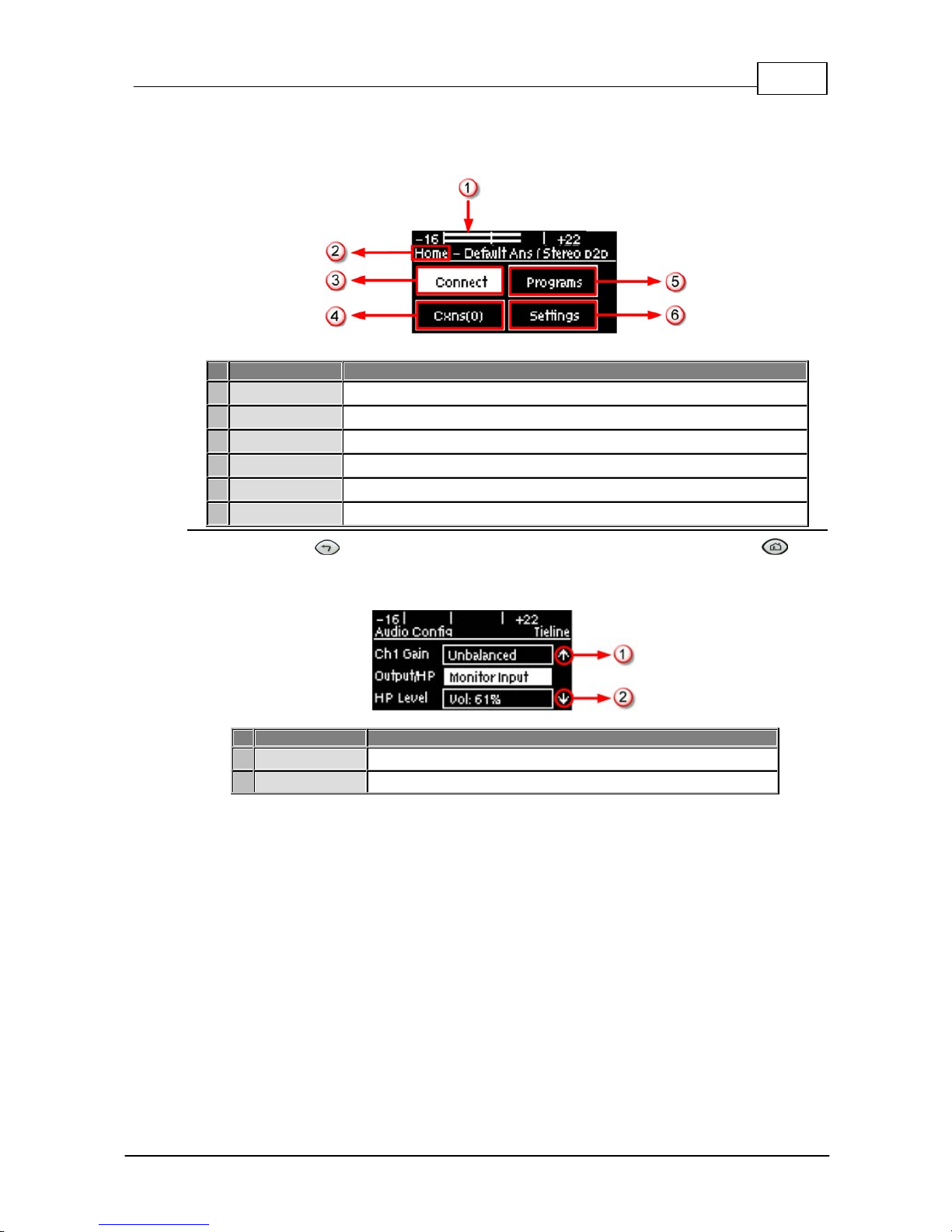
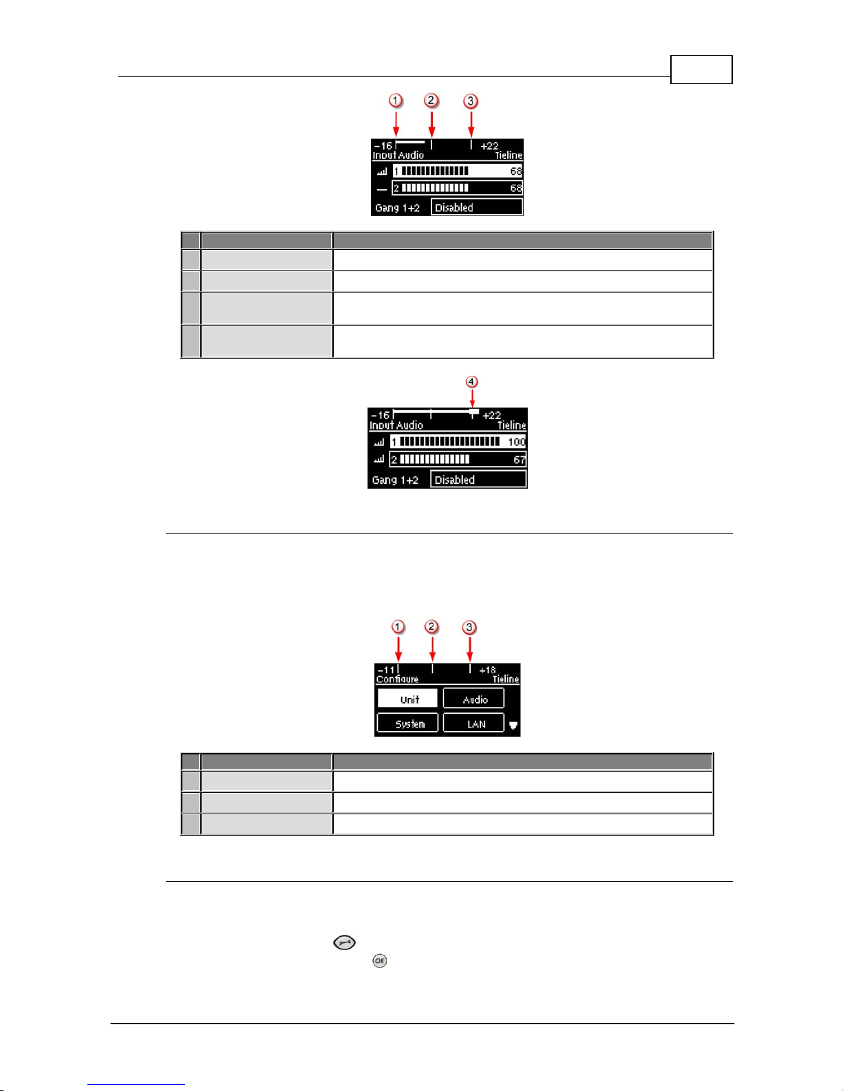
Bridge-IT Hom e Screen
Features
Codec Home S cre en Elem ents
1
PPM Meters
Left (top) and right channel audio levels
2
Screen Name
The name of the current screen being navigated
3
Connect
Select to dial & adjust connection settings
4
Cxns
Displays the number of current connections
5
Programs
View and edit Program dialing configurations
6
Settings
Select to configure codec settings
Press the RETURN button to navigate backwards through menus, or press the HOME
button to return to the Home sc reen from any menu. If a full menu cannot be viewed on the codec
sc reen then arrows on the right hand side of the screen indicate that the current menu has items
below and/or above t he items c urrently visible. Use the navigation arrows t o scroll up and down.
Features
Codec Home S cre en Elem ents
1
Up Arrow
Arrow indicating menus can scroll upwards
2
Down Arrow
Arrow indicating menus can scroll downwards
18 Bridge-IT X TRA Ma nual
© Tieline Pty. Lt d. 2015
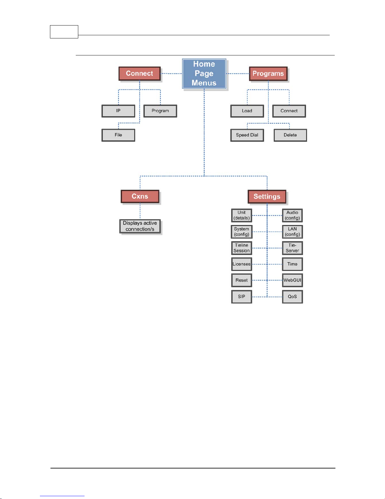
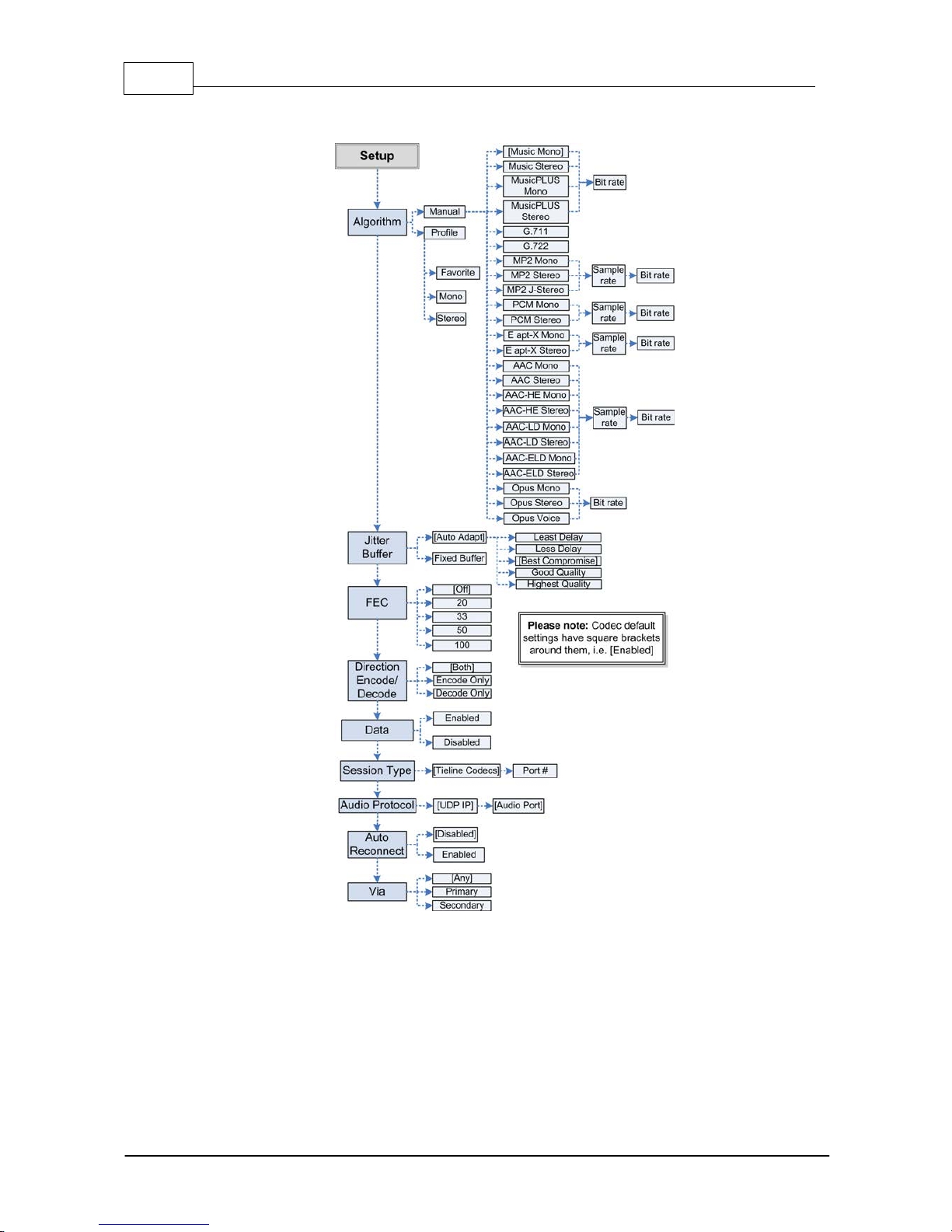
Codec Menu Overview
19
© Tieline Pty. Lt d. 2015
Bridge-IT X TRA Ma nual
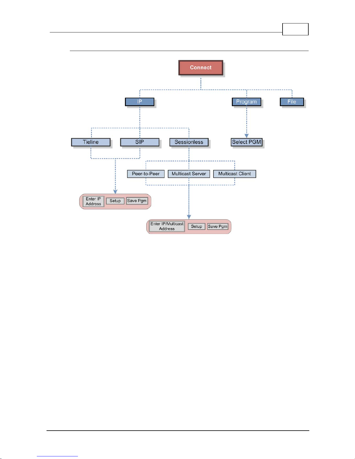
Connect Menu
20 Bridge-IT X TRA Ma nual
© Tieline Pty. Lt d. 2015
IP Setup Menu Navigati on
21
© Tieline Pty. Lt d. 2015
Bridge-IT X TRA Ma nual
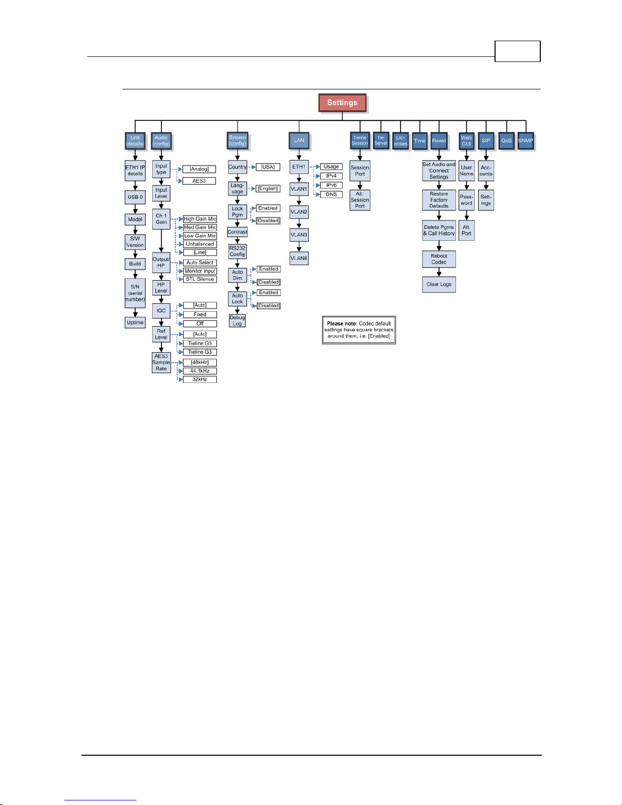
Settings Menu
22 Bridge-IT X TRA Ma nual
© Tieline Pty. Lt d. 2015
8 Adjusting Input/Meter Leve ls
The codec uses dBu to express nominal operating level, headroom and noise floor levels. The PPM
meters display input audio by default when the codec is not connected and they then switch to
monitor decoded return program audio after making a connection.
Mono and Stereo Audio Capabilit i es
The codec sends input 1 directly to the left output and input 2 directly to the right output. When
sending mono analog audio select a mono algorithm in the IP Connect Setup menu and connect
audio to input 1 of the codec. Input audio is replicated and sent to both channel 1 and 2 analog XLR
outputs in this mode. The AES3 outputs are directly mapped to both the analog and digital inputs,
therefore if a mono analog profile is selected, only channel one will have audio on it over AES3.
Note: It is not possible to mix channels 1 and 2 into dual mono outputs.
The codec will provide both analog and digital audio out at all times and this is not dependent on
whether your audio source is analog or digital. The only point to note is that when you configure a
mono analog connection the codec will only send audio on one of the AES3 outputs, but it will send
audio on both the left and right channels of the analog outputs.
Adjusti ng Audio M eter Reference Scale Settings
When connected to stereo sources the top PPM meter is the left channel and the bottom PPM
meter is the right channel. The codec is configured by default to automatically connect to other
Tieline codecs using the correct audio reference meter scales. The audio reference level settings in
the codec are:
Reference S etting
Description
1
Auto (default)
When connecting to a Tieline codec with session data enabled
the codec will automatically adjust the reference level for G5 and
G3 codecs. When connecting to a non-Tieline codec, or a Tieline
codec without session data enabled, the codec will use the
Tieline G5 setting.
2
Tieline G5
The audio reference scale is -16dBu to +22dBu
3
Tieline G3
The audio reference scale is -11dBu and +18dBu
To configure this setting manually:
1. Press the SETTINGS button.
2. Navigate to Audio and press .
3. Navigate to Ref Level and press .
4. Select the preferred setting and press .
Audio Meteri ng when Connecti ng to Tieli ne G5 Codecs
The Tieline G5 audio reference scale displayed on the codec screen is -16dBu to +22dBu when
you connect to a codec in Tieline's Merlin, Genie or Bridge-IT IP codec families. Set audio levels so
that audio peaks average at the nominal 0vu point. This represents a program level of +4 dBu leaving
the codec. Audio peaks can safely reach +22 dBu without clipping, providing 18dBu of headroom
from the nominal 0vu point. The default PPM audio meter indications are as follows.
23
© Tieline Pty. Lt d. 2015
Bridge-IT X TRA Ma nual
Features
Description
1
-16dBu
PPM meter low point
2
+4dBu
Nominal 0vu reference level at +4dBu
3
+20dBu
+20dBu indication that should not be exceeded to prevent clipping
at +22dBu
4
PPM meter in clip
PPM indication displays a solid section at the right-hand end
when audio is in danger of clipping
Audio Meter i ng when Connecting to Tieline G3 Codecs
New generation Genie, Merlin and Bridge-IT IP codecs have more audio headroom than Tieline G3
audio codecs, therefore metering needs to be adjusted when connecting to a Commander or i-Mix
G3 codec. The G3 metering scale is between -11dBu and +18dBu and audio levels should average
around the nominal 0vu point. Audio peaks should not exceed +16dbu as indicated on the PPM
meter.
Features
Description
1
-11dBu
PPM meter low point
2
+4dBu
Nominal 0vu reference level at +4dBu
3
+16dBu
+16 indication where audio will clip/distort
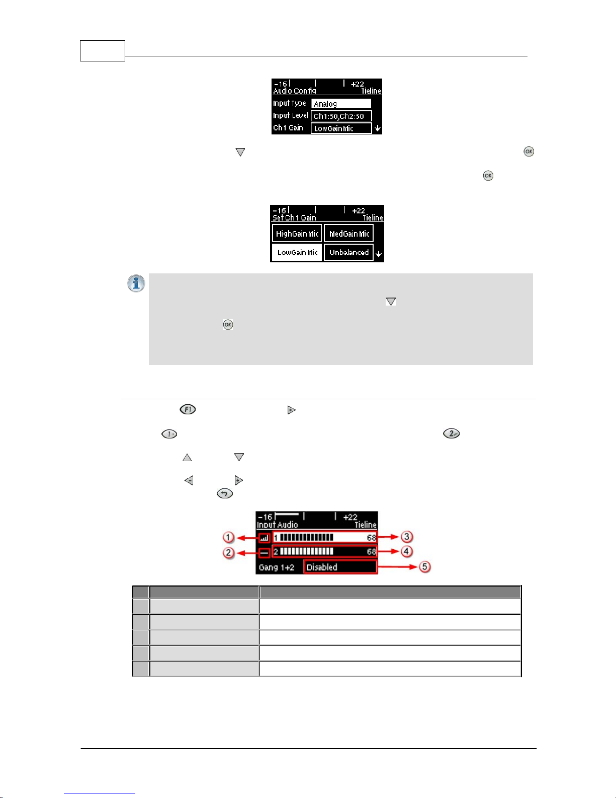
Channel 1 Mi c/ Line Level A udio Adj ustment
The default input level setting in the codec for channel 1 is line level. To adjust this setting for a miclevel or unbalanced source:
1. Press the SETTINGS button.
2. Navigate to Audio and press .
24 Bridge-IT X TRA Ma nual
© Tieline Pty. Lt d. 2015
3. Ensure Input Type is set to Analog.
4. Use the arrow-down button to highlight and select the Ch 1 Gain setting and press the
button.
5. Use the navigation buttons to select the appropriate gain setting and press the button to
save the setting.
Importa n t Note: 15 volt phantom power is not s upplied to input 1 by default . To turn this on:
1. Select Settings > Audio and use the arrow-down button to highlight the Phantom
setting.
2. Press the button to togg le between Enabled and Disabled.
Channel 2 is a line input only and gain can only be adjusted using the In put Audio screen
on the codec.
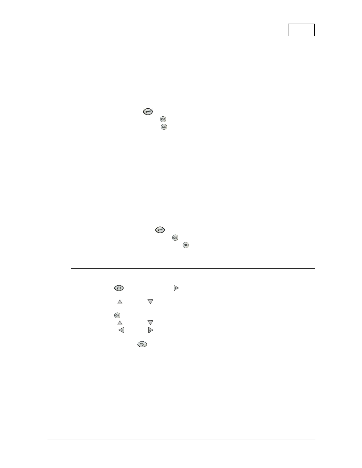
Quick A djustm ent of I nput Levels
1. Press the button and the right arrow button to open the Input Audio level adjustment
screen.
2. Press on the numeric keypad to toggle channel 1 on and off and press to toggle channel
2 on and off.
3. Use the up and down arrow buttons to navigate to the channel you want to adjust. Note: A
channel is highlighted when selected.
4. Use the left and right arrow buttons to adjust the input levels up or down.
5. Press the RETURN button to exit t he sc reen.
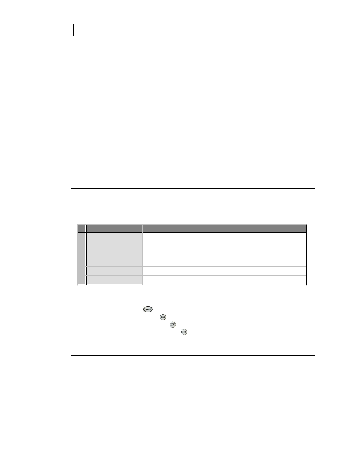
Input Audio Fe atures
Description
1
Channel On Symbol
Symbol indicates a channel is turned on
2
Channel Off S y m bol
Symbol indicates a channel is turned off
3
Input 1 Level Control
Ch 1 level indication with percentage of gain indicated, i.e. 68.
4
Inp ut 2 Level Contro l
Ch 1 level indication with percentage of gain indicated, i.e. 68
5
Ch1/2 Gang Indication
Indicates whether ganging is enabled or disabled
25
© Tieline Pty. Lt d. 2015
Bridge-IT X TRA Ma nual
Intell i gent G ai n Control (I G C)
When the broadcast action really starts to heat up, the codec's inbuilt DSP limiter automatically
takes care of any instantaneous audio peaks that occur in demanding broadcast situations. IGC
(Intelligent Gain Control) is enabled by default and is activated at +20 dBu (G5 audio scale) and
+14dBu (G3 audio scale) to prevent audio clipping. IGC automatically adjusts high audio input levels
downwards until they are acceptable. If IGC auto level recovery (IGC Level) is not enabled, the input
level will remain at the adjusted point until the input gain is manually adjusted again by the user. If
IGC is active in the codec it is indicated in the PPM meter section. To adjust this setting:
1. Press the SETTINGS button.
2. Navigate to Audio and press .
3. Navigate to IGC and press to toggle between Enabled and Disabled.
IGC A uto Level Recovery
IGC Level works with IGC to detect when incoming audio levels have reduced sufficiently.
There are two settings; Auto and Fixed.
If the IGC Level setting is Auto then the codec will return input levels to the gain setting prior
to IGC being activated. The codec takes just 250 milliseconds to detect audio levels have
returned to normal (after IGC Level has been initiated) and will then return the levels to the
previous setting within half a second. This response is linear.
If the setting is Fixed then audio levels will remain lower and not return to the original setting.
To adjust this setting:
1. Press the SETTINGS button.
2. Navigate to Audio and press .
3. Navigate to IGC Level and press to toggle between Auto and Fixed.
Ganging Audio Channels
Ganging allows you to adjust the audio level of both inputs simultaneously.
1. Press the button and the right arrow button to open the Input Audio level adjustment
screen.
2. Use the up and down arrow buttons to navigate to and select Gang 1 + 2 Enabl ed or
Disabled.
3. Press the button to select Enabled.
4. Use the up and down arrow buttons to highlight and select the audio channels.
5. Use the left and right arrow buttons to adjust the levels for both inputs up or down
simultaneously.
6. Press the RETURN button to exit t he sc reen.
When channels 1 and 2 are ganged together:
· Both channels highlight together when selected.
· You can adjust the audio of both channels simultaneously.
· The gain setting for both channels is automatically set to match the gain level of the lowest of
the two channels when ganging is configured.
· If one channel is turned on when ganging is configured then the other one will be turned on
automatically.
26 Bridge-IT X TRA Ma nual
© Tieline Pty. Lt d. 2015
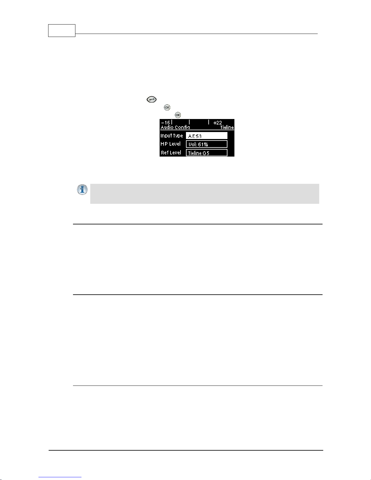
9 Configuring AES3 Audio
If your input source is AES3 (AES/EBU) format use the IN1/AES3 IN input on the rear panel of the
codec. This is a balanced 110 ohm female XLR input and can operate effectively over distances of up
to 100 meters. The input accepts both mono and stereo AES3 signals as only a s ingle 3 pin XLR
input or output is required for sending and receivi ng two channels of AES 3 data. To configure the
codec to acc ept A E S3 data si gnals:
1. Press the SETTINGS button.
2. Navigate to Audio and press .
3. Select Input Type and press the button to toggle from Analog to AES/EBU.
The 3 pin male XLR AES3 output on the rear panel is labeled AES3 OUT. It is capable of sending
both mono and stereo AES3 signals.
Importa n t Note: Input levels are set at 100% automatically for AES3 c onnections. If you
switc h back t o the analog input set t ing after selecting AES3, t he previous analog settings
will be recov ered .
AES/EBU Sample Rate Conversi on
The codec implements an Asynchronous Sample Rate Converter (ASRC) to convert the sample rate
of the AES3 input to the sample rate set in the codec. The codec sample rate is determined by the
selected algorithm. For example, if you select the Music algorithm, the sample rate will be set to
32kHz when the codec is connected.
The codec accepts AES3 input sample rates of 32kHz, 44.1kHz or 48kHz. The output sample rate
is determined by the algorithm used when connected.
AES3 Audio Out & SD Card Sample Rate
1. When you are not connected, you can adjust the AES3 output sample rate manually in the
Audio menu via the AES3 SR setting.
2. If file playback occurs before a connection is initiated, the AES3 output sample rate will match
the audio file sample rate.
3. For best performance, the SD card file sample rate should match the AES3 SR setting in the
codec and the algorithm sample rate. If they don't match, the codec will re-sample the SD card
file audio to match the connection sample rate, and this will be used by the AES3 output. For
example, if you are streaming audio using Tieline Music (32kHz sampling), file playback will be
re-sampled to 32kHz if the SD card file is 44.1kHz or 48kHz. In this example the AES3 output
sample rate will be 32kHz.
Adjusti ng the Codec Output Sample Rate
As there is no external reference clock for the codec it is necessary to set the output sample rate of
the codec when you are not connected. The AES3 SR setting in the Audio menu will configure
audio outputs and audio monitoring, as well as SD card playback at this sample rate. The default
setting is 48kHz sampling:

27
© Tieline Pty. Lt d. 2015
Bridge-IT X TRA Ma nual
1. Press the SETTINGS button.
2. Navigate to Audio and press .
3. Navigate to AES3 SR and press .
4. Select a preferred sample rate then press .
Tieline normally recommends selecting STL Silence Mode for audio monitoring if using AES3. If
using Auto Select make sure the algorithm sample rate and the AES3 SR sample rate setting are
the same.

28 Bridge-IT X TRA Ma nual
© Tieline Pty. Lt d. 2015
10 Headp h o n e/Output Monitoring
The 6.35mm (1/4") stereo headphone output on the codec c an be used for monitoring audio inputs 1
and 2 and return link audio .
Importa n t Note: When the codec makes a connection it will monitor the decoded return
audio link by default.
Adjusti ng Headphone Output Levels
When using analog or digital inputs y ou will see input audio on the PPMs and hear it in the
headphones.
1. Press and hold the button and then press the right arrow button to display the H/P
Volume adjustment screen.
2. Use the left or right navigation buttons to adjust the volume levels up or down. The screen
displays level adjustments in real-time.
3. Press when you have finished.
Headphone levels can also be adjusted by navigating to SETTINGS > Audio and using the
down button to navigate to HP Level and press .
Output/Headphone Monit ori ng Settings
There are three Output/HP monitoring configurations available in the codec. The default setting is
Auto Select and to adjust this setting:
1. Press the SETTINGS button.
2. Navigate to Audio and press .
3. Navigate to Output/HP and press to select either Monitor Input or STL Silence.
The table below displays how audio is routed to the codec outputs/headphones based on the
configuration selected and the current codec state (IP streaming or idle). Please note:
· The same audio is always routed to the headphone and XLR outputs.
· Output 1 corresponds to headphone left and output 2 corresponds headphone right.
· The same audio is routed to the analog and AES XLR outputs.
· When inputs are routed to the outputs, input 1 is sent to output 1 and input 2 is sent to output
2.

29
© Tieline Pty. Lt d. 2015
Bridge-IT X TRA Ma nual
Codec Connection S ta te
Mode
Idle
Streami ng (Mono)
Streami ng (Ste reo)
Auto Select
(default)
Inputs
Same decoded audio
on all outputs
Channel 1 decoded
on output 1, and
channel 2 decoded on
output 2
STL Silence
No audio
Same decoded audio
on all outputs
Channel 1 decoded
on output 1, and
channel 2 decoded on
output 2
Monitor Input
Inputs
Inputs
Inputs
Auto Select M ode
Auto Select is the default Output/HP monitoring setting in the codec. Use this setting if you
want to monitor the inputs when not connected and return audio when connected.
Monitor I nput Mode
Select Monitor Input to configure the codec to always monitor input audio. This may be useful
if an announcer wants to monitor their own voice and not return audio when connected.
STL Sil ence Mode
1. In STL Silence mode input audio is not monitored on the PPMs or via the headphone output
before the codec is connected. It is necessary to check input audio levels using Auto Select
or Monitor Input modes prior to connecting.
2. When the codec connects in STL Silence mode it automatically monitors decoded incoming
audio.
3. If the connection is lost for any reason then silence is enabled, ensuring input audio cannot
be misconstrued as return program audio for STL connections.
4. If the connection is subsequently restored the codec will again monitor decoded incoming
audio.
11 Langu age Selection
English is t he default language in the codec. To adjust t his setting:
1. Press the SETTINGS button.
2. Navigate to System and press .
3. Use the navigation buttons to select Language and press .
4. Select a language and press .

30 Bridge-IT X TRA Ma nual
© Tieline Pty. Lt d. 2015
12 About Program Dialin g
What Defines a Program?
The codec uses the concept of 'program' dialing to connect using peer-to-peer, multicast or multiunicast connections. A Program configures a Tieline codec to send or receive an Audio Stream.
The attributes of each audio stream and associated connections are embodied within a program
when it is created, including the configuration, dialing and answering parameters. Essentially a
program is like a connection profile with:
· A Program Name.
· IP address dialing details for up to 6 connection end-points or a multicast IP address.
· Specific connection profile details pertaining to algorithm, FEC, jitter buffer and bit-rate
settings etc.
Custom programs allow you to store connection settings for a range of peer-to-peer, multicast and
multi-unicast connections and retrieve or edit them easily at the touch of a button. Simple peer-topeer or multicast profiles can be created using the codec front panel, whereas multi-unicasts must
be created with the Programs panel in the Toolbox web-GUI.
Using Programs to Dial between Two Tieli ne Codecs
Tieline Bridge-IT and Bridge-IT XTRA codecs operate similarly to Tieline G3 codecs. By default,
Tieline codecs send proprietary session data when connecting to each other in order to establish,
manage and terminate connections. When a connection between two codecs is established:
1. The dialing codec sends information about how the codec receiving the call should be
configured.
2. Once the codec receiving session data from the dialing codec has received information
successfully, it sends an acknowledgement to the dialing codec and streaming can
commence.
If you configure a stereo program on the dialing codec using a particular algorithm and bit rate etc.,
these settings will be configured on the answering codec when it connects. It is also possible to
lock a loaded program in a codec to ensure the currently loaded program cannot be unloaded by a
codec dialing in with different program settings.
Creating Programs
Simple peer-to-peer (point-to-point) programs can be created using the codec front panel. The
Toolbox web-GUI contains a Programs panel with a wizard for configuring program settings and
backup connections. Edit settings easily at the touch of a button and use existing programs as
templates for creating other programs.
Mono and Stereo Peer-to-Peer Programs
New peer-to-peer programs can be created using the codec front panel keypad (see 10 Quick
Steps to Connect). If you know the IP address of the codec you want to dial then all you need to
do is enter this into the codec, choose your preferred connection settings and then press
CONNECT .
Front panel configured programs are automatically saved as Recent Programs which retain all
the audio stream dialing and configuration information. These Recent Programs are displayed
when you press the CONNECT button from within any menu except the IP Mode or SIP
Mode screens, or the Connect IP or Connect SIP screens.
 Loading...