

Page 1
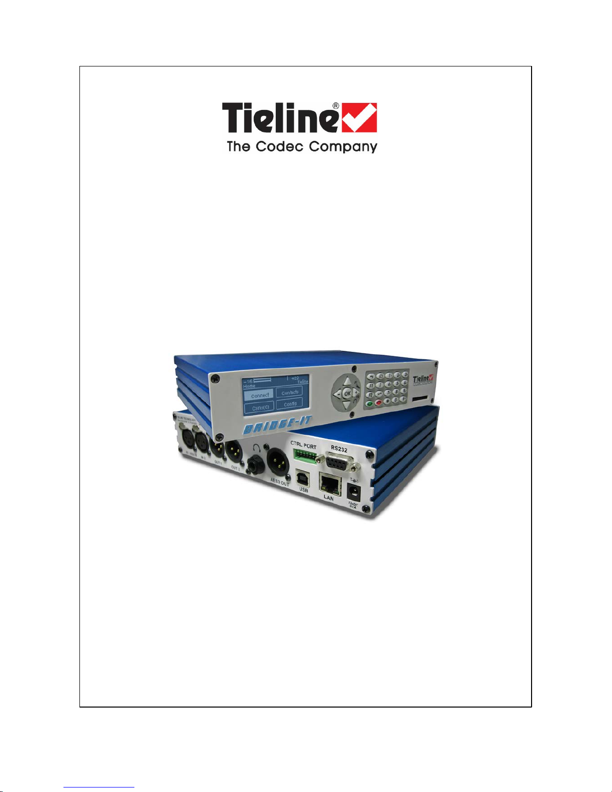
Bridge-IT
IP Codec User Manual
Software Version: 2.14.88
Manual Version: v.2.2_20151125
November, 2015
Page 2

Bridge-IT M anua l2
© Tieline Pty. Lt d. 2015
Table of Contents
Part I How to Use the Documentation
5
Part II W arnings and Safety Informati on
6
Part III Glossary of Terms
7
Part IV Introduction to the Codec
9
Part V Front Panel Controls
11
Part VI Rear Panel Connections
13
Part VII Navigating Codec Menus
15
Part VIII A djusting Input/Meter Levels
20
Part IX Configuring AES3 Audio
24
Part X Headphone/Output Monitoring
26
Part XI Language Selecti on
27
Part XII About Program Dialing
28
Part XIII Getting Connected Quickly
30
... . . . . . . . . . . . . . . . . . . . . . . . . . . . . . . . . . . . . . . . . .... . . . . . . . . . . . . . . . . . . . . . . . . . . . . . . . . . . . . . . . . . . .... . . . . . . . . . . . . . . . . . . . . . . . . . . . . . . . . . . . . . . 301 10 Quick Steps to Connect Bridge-IT
... . . . . . . . . . . . . . . . . . . . . . . . . . . . . . . . . . . . . . . . . .... . . . . . . . . . . . . . . . . . . . . . . . . . . . . . . . . . . . . . . . . . . .... . . . . . . . . . . . . . . . . . . . . . . . . . . . . . . . . . . . . . . 332 Monitoring IP Connections
... . . . . . . . . . . . . . . . . . . . . . . . . . . . . . . . . . . . . . . . . .... . . . . . . . . . . . . . . . . . . . . . . . . . . . . . . . . . . . . . . . . . . .... . . . . . . . . . . . . . . . . . . . . . . . . . . . . . . . . . . . . . . 353 Load and Dial Cus t om Programs
... . . . . . . . . . . . . . . . . . . . . . . . . . . . . . . . . . . . . . . . . .... . . . . . . . . . . . . . . . . . . . . . . . . . . . . . . . . . . . . . . . . . . .... . . . . . . . . . . . . . . . . . . . . . . . . . . . . . . . . . . . . . . 354 Disc onnecting a Connection
... . . . . . . . . . . . . . . . . . . . . . . . . . . . . . . . . . . . . . . . . .... . . . . . . . . . . . . . . . . . . . . . . . . . . . . . . . . . . . . . . . . . . .... . . . . . . . . . . . . . . . . . . . . . . . . . . . . . . . . . . . . . . 365 Redialing a Connection
... . . . . . . . . . . . . . . . . . . . . . . . . . . . . . . . . . . . . . . . . .... . . . . . . . . . . . . . . . . . . . . . . . . . . . . . . . . . . . . . . . . . . .... . . . . . . . . . . . . . . . . . . . . . . . . . . . . . . . . . . . . . . 366 Configuring Auto Reconnect
... . . . . . . . . . . . . . . . . . . . . . . . . . . . . . . . . . . . . . . . . .... . . . . . . . . . . . . . . . . . . . . . . . . . . . . . . . . . . . . . . . . . . .... . . . . . . . . . . . . . . . . . . . . . . . . . . . . . . . . . . . . . . 377 Speed Dialing Connections
... . . . . . . . . . . . . . . . . . . . . . . . . . . . . . . . . . . . . . . . . .... . . . . . . . . . . . . . . . . . . . . . . . . . . . . . . . . . . . . . . . . . . .... . . . . . . . . . . . . . . . . . . . . . . . . . . . . . . . . . . . . . . 378 Dial/Disconnect Multiple Connections
... . . . . . . . . . . . . . . . . . . . . . . . . . . . . . . . . . . . . . . . . .... . . . . . . . . . . . . . . . . . . . . . . . . . . . . . . . . . . . . . . . . . . .... . . . . . . . . . . . . . . . . . . . . . . . . . . . . . . . . . . . . . . 389 Creating a Multicast Server Program
... . . . . . . . . . . . . . . . . . . . . . . . . . . . . . . . . . . . . . . . . .... . . . . . . . . . . . . . . . . . . . . . . . . . . . . . . . . . . . . . . . . . . .... . . . . . . . . . . . . . . . . . . . . . . . . . . . . . . . . . . . . . . 4110 Creating a Multicast Client Program
... . . . . . . . . . . . . . . . . . . . . . . . . . . . . . . . . . . . . . . . . .... . . . . . . . . . . . . . . . . . . . . . . . . . . . . . . . . . . . . . . . . . . .... . . . . . . . . . . . . . . . . . . . . . . . . . . . . . . . . . . . . . . 4311 Dialing SIP Peer-to-Peer
... . . . . . . . . . . . . . . . . . . . . . . . . . . . . . . . . . . . . . . . . .... . . . . . . . . . . . . . . . . . . . . . . . . . . . . . . . . . . . . . . . . . . .... . . . . . . . . . . . . . . . . . . . . . . . . . . . . . . . . . . . . . . 4412 Dialing SIP Addresses
... . . . . . . . . . . . . . . . . . . . . . . . . . . . . . . . . . . . . . . . . .... . . . . . . . . . . . . . . . . . . . . . . . . . . . . . . . . . . . . . . . . . . .... . . . . . . . . . . . . . . . . . . . . . . . . . . . . . . . . . . . . . . 4513 Deleting Programs
... . . . . . . . . . . . . . . . . . . . . . . . . . . . . . . . . . . . . . . . . .... . . . . . . . . . . . . . . . . . . . . . . . . . . . . . . . . . . . . . . . . . . .... . . . . . . . . . . . . . . . . . . . . . . . . . . . . . . . . . . . . . . 4514 Selecting Algorithm Profiles
... . . . . . . . . . . . . . . . . . . . . . . . . . . . . . . . . . . . . . . . . .... . . . . . . . . . . . . . . . . . . . . . . . . . . . . . . . . . . . . . . . . . . .... . . . . . . . . . . . . . . . . . . . . . . . . . . . . . . . . . . . . . . 4815 SDHC Card Backup
... . . . . . . . . . . . . . . . . . . . . . . . . . . . . . . . . . . . . . . . . .... . . . . . . . . . . . . . . . . . . . . . . . . . . . . . . . . . . . . . . . . . . .... . . . . . . . . . . . . . . . . . . . . . . . . . . . . . . . . . . . . . . 4816 SDHC Card File Playback
... . . . . . . . . . . . . . . . . . . . . . . . . . . . . . . . . . . . . . . . . .... . . . . . . . . . . . . . . . . . . . . . . . . . . . . . . . . . . . . . . . . . . .... . . . . . . . . . . . . . . . . . . . . . . . . . . . . . . . . . . . . . . 4917 Lock or Unlock a Program in the Codec
... . . . . . . . . . . . . . . . . . . . . . . . . . . . . . . . . . . . . . . . . .... . . . . . . . . . . . . . . . . . . . . . . . . . . . . . . . . . . . . . . . . . . .... . . . . . . . . . . . . . . . . . . . . . . . . . . . . . . . . . . . . . . 5018 Locking the Front Panel
Page 3

3Contents
© Tieline Pty. Lt d. 2015
Part XIV Connecting to the ToolBox
Web-GUI
51
... . . . . . . . . . . . . . . . . . . . . . . . . . . . . . . . . . . . . . . . . .... . . . . . . . . . . . . . . . . . . . . . . . . . . . . . . . . . . . . . . . . . . .... . . . . . . . . . . . . . . . . . . . . . . . . . . . . . . . . . . . . . . 521 Opening the Java or HTML5 Web-GUI & Login
... . . . . . . . . . . . . . . . . . . . . . . . . . . . . . . . . . . . . . . . . .... . . . . . . . . . . . . . . . . . . . . . . . . . . . . . . . . . . . . . . . . . . .... . . . . . . . . . . . . . . . . . . . . . . . . . . . . . . . . . . . . . . 552 Changing the Default Pas sword
... . . . . . . . . . . . . . . . . . . . . . . . . . . . . . . . . . . . . . . . . .... . . . . . . . . . . . . . . . . . . . . . . . . . . . . . . . . . . . . . . . . . . .... . . . . . . . . . . . . . . . . . . . . . . . . . . . . . . . . . . . . . . 563 Installing USB Drivers
... . . . . . . . . . . . . . . . . . . . . . . . . . . . . . . . . . . . . . . . . .... . . . . . . . . . . . . . . . . . . . . . . . . . . . . . . . . . . . . . . . . . . .... . . . . . . . . . . . . . . . . . . . . . . . . . . . . . . . . . . . . . . 574 Launching the GUI over USB
Part XV Java Toolbox Web-GUI
Introduction
57
Part XVI Java Toolbox Web-GUI Codec
Configuration
65
... . . . . . . . . . . . . . . . . . . . . . . . . . . . . . . . . . . . . . . . . .... . . . . . . . . . . . . . . . . . . . . . . . . . . . . . . . . . . . . . . . . . . .... . . . . . . . . . . . . . . . . . . . . . . . . . . . . . . . . . . . . . . 651 Configuring IP Settings
... . . . . . . . . . . . . . . . . . . . . . . . . . . . . . . . . . . . . . . . . .... . . . . . . . . . . . . . . . . . . . . . . . . . . . . . . . . . . . . . . . . . . .... . . . . . . . . . . . . . . . . . . . . . . . . . . . . . . . . . . . . . . 692 Configuring Input/Output Settings
... . . . . . . . . . . . . . . . . . . . . . . . . . . . . . . . . . . . . . . . . .... . . . . . . . . . . . . . . . . . . . . . . . . . . . . . . . . . . . . . . . . . . .... . . . . . . . . . . . . . . . . . . . . . . . . . . . . . . . . . . . . . . 733 Configuring Mono or Stereo Peer-to-Peer Programs
... . . . . . . . . . . . . . . . . . . . . . . . . . . . . . . . . . . . . . . . . .... . . . . . . . . . . . . . . . . . . . . . . . . . . . . . . . . . . . . . . . . . . .... . . . . . . . . . . . . . . . . . . . . . . . . . . . . . . . . . . . . . . 794 Configuring Multi-U nicast Dialing Programs
... . . . . . . . . . . . . . . . . . . . . . . . . . . . . . . . . . . . . . . . . .... . . . . . . . . . . . . . . . . . . . . . . . . . . . . . . . . . . . . . . . . . . .... . . . . . . . . . . . . . . . . . . . . . . . . . . . . . . . . . . . . . . 845 Configuring Multicas t Server Programs
... . . . . . . . . . . . . . . . . . . . . . . . . . . . . . . . . . . . . . . . . .... . . . . . . . . . . . . . . . . . . . . . . . . . . . . . . . . . . . . . . . . . . .... . . . . . . . . . . . . . . . . . . . . . . . . . . . . . . . . . . . . . . 886 Configuring Multicas t Client Programs
... . . . . . . . . . . . . . . . . . . . . . . . . . . . . . . . . . . . . . . . . .... . . . . . . . . . . . . . . . . . . . . . . . . . . . . . . . . . . . . . . . . . . .... . . . . . . . . . . . . . . . . . . . . . . . . . . . . . . . . . . . . . . 917 Configuring SIP Settings
... . . . . . . . . . . . . . . . . . . . . . . . . . . . . . . . . . . . . . . . . .... . . . . . . . . . . . . . . . . . . . . . . . . . . . . . . . . . . . . . . . . . . .... . . . . . . . . . . . . . . . . . . . . . . . . . . . . . . . . . . . . . . 938 Configuring SIP Programs
... . . . . . . . . . . . . . . . . . . . . . . . . . . . . . . . . . . . . . . . . .... . . . . . . . . . . . . . . . . . . . . . . . . . . . . . . . . . . . . . . . . . . .... . . . . . . . . . . . . . . . . . . . . . . . . . . . . . . . . . . . . . . 979 Dial and Dis c onnect a Program
... . . . . . . . . . . . . . . . . . . . . . . . . . . . . . . . . . . . . . . . . .... . . . . . . . . . . . . . . . . . . . . . . . . . . . . . . . . . . . . . . . . . . .... . . . . . . . . . . . . . . . . . . . . . . . . . . . . . . . . . . . . . . 9810 Dial and Disconnect Multi-unicast Connections
... . . . . . . . . . . . . . . . . . . . . . . . . . . . . . . . . . . . . . . . . .... . . . . . . . . . . . . . . . . . . . . . . . . . . . . . . . . . . . . . . . . . . .... . . . . . . . . . . . . . . . . . . . . . . . . . . . . . . . . . . . . . . 10011 Lock or Unlock Programs
... . . . . . . . . . . . . . . . . . . . . . . . . . . . . . . . . . . . . . . . . .... . . . . . . . . . . . . . . . . . . . . . . . . . . . . . . . . . . . . . . . . . . .... . . . . . . . . . . . . . . . . . . . . . . . . . . . . . . . . . . . . . . 10012 View/Edit/Delete Programs
... . . . . . . . . . . . . . . . . . . . . . . . . . . . . . . . . . . . . . . . . .... . . . . . . . . . . . . . . . . . . . . . . . . . . . . . . . . . . . . . . . . . . .... . . . . . . . . . . . . . . . . . . . . . . . . . . . . . . . . . . . . . . 10313 Res et Factory Default Settings
... . . . . . . . . . . . . . . . . . . . . . . . . . . . . . . . . . . . . . . . . .... . . . . . . . . . . . . . . . . . . . . . . . . . . . . . . . . . . . . . . . . . . .... . . . . . . . . . . . . . . . . . . . . . . . . . . . . . . . . . . . . . . 10414 Backup and Rest ore Functions
... . . . . . . . . . . . . . . . . . . . . . . . . . . . . . . . . . . . . . . . . .... . . . . . . . . . . . . . . . . . . . . . . . . . . . . . . . . . . . . . . . . . . .... . . . . . . . . . . . . . . . . . . . . . . . . . . . . . . . . . . . . . . 10615 Web-GUI Soft ware Licens e Ins tallation
... . . . . . . . . . . . . . . . . . . . . . . . . . . . . . . . . . . . . . . . . .... . . . . . . . . . . . . . . . . . . . . . . . . . . . . . . . . . . . . . . . . . . .... . . . . . . . . . . . . . . . . . . . . . . . . . . . . . . . . . . . . . . 10716 Download Logs
... . . . . . . . . . . . . . . . . . . . . . . . . . . . . . . . . . . . . . . . . .... . . . . . . . . . . . . . . . . . . . . . . . . . . . . . . . . . . . . . . . . . . .... . . . . . . . . . . . . . . . . . . . . . . . . . . . . . . . . . . . . . . 10817 RS232 Data Configuration
... . . . . . . . . . . . . . . . . . . . . . . . . . . . . . . . . . . . . . . . . .... . . . . . . . . . . . . . . . . . . . . . . . . . . . . . . . . . . . . . . . . . . .... . . . . . . . . . . . . . . . . . . . . . . . . . . . . . . . . . . . . . . 10918 Creating Rules
... . . . . . . . . . . . . . . . . . . . . . . . . . . . . . . . . . . . . . . . . .... . . . . . . . . . . . . . . . . . . . . . . . . . . . . . . . . . . . . . . . . . . .... . . . . . . . . . . . . . . . . . . . . . . . . . . . . . . . . . . . . . . 11319 Upgrading Codec Firmware
Part XVII HTML5 Toolbox Web-GUI
Introduction
115
Part XVIII HTML5 Toolbox Web-GUI
Configuration
126
... . . . . . . . . . . . . . . . . . . . . . . . . . . . . . . . . . . . . . . . . .... . . . . . . . . . . . . . . . . . . . . . . . . . . . . . . . . . . . . . . . . . . .... . . . . . . . . . . . . . . . . . . . . . . . . . . . . . . . . . . . . . . 1261 Using the HTML5 Toolbox Quick Connect Web-GUI
... . . . . . . . . . . . . . . . . . . . . . . . . . . . . . . . . . . . . . . . . .... . . . . . . . . . . . . . . . . . . . . . . . . . . . . . . . . . . . . . . . . . . .... . . . . . . . . . . . . . . . . . . . . . . . . . . . . . . . . . . . . . . 1312 Configuring IP Settings
... . . . . . . . . . . . . . . . . . . . . . . . . . . . . . . . . . . . . . . . . .... . . . . . . . . . . . . . . . . . . . . . . . . . . . . . . . . . . . . . . . . . . .... . . . . . . . . . . . . . . . . . . . . . . . . . . . . . . . . . . . . . . 1353 Configuring Input/Output Settings
... . . . . . . . . . . . . . . . . . . . . . . . . . . . . . . . . . . . . . . . . .... . . . . . . . . . . . . . . . . . . . . . . . . . . . . . . . . . . . . . . . . . . .... . . . . . . . . . . . . . . . . . . . . . . . . . . . . . . . . . . . . . . 1374 Configure SIP Settings
... . . . . . . . . . . . . . . . . . . . . . . . . . . . . . . . . . . . . . . . . .... . . . . . . . . . . . . . . . . . . . . . . . . . . . . . . . . . . . . . . . . . . .... . . . . . . . . . . . . . . . . . . . . . . . . . . . . . . . . . . . . . . 1405 Load, Unload and Dial a Program
... . . . . . . . . . . . . . . . . . . . . . . . . . . . . . . . . . . . . . . . . .... . . . . . . . . . . . . . . . . . . . . . . . . . . . . . . . . . . . . . . . . . . .... . . . . . . . . . . . . . . . . . . . . . . . . . . . . . . . . . . . . . . 1436 Lock or Unlock Programs
Page 4

Bridge-IT M anua l4
© Tieline Pty. Lt d. 2015
... . . . . . . . . . . . . . . . . . . . . . . . . . . . . . . . . . . . . . . . . .... . . . . . . . . . . . . . . . . . . . . . . . . . . . . . . . . . . . . . . . . . . .... . . . . . . . . . . . . . . . . . . . . . . . . . . . . . . . . . . . . . . 1447 Reset Factory Default Settings
... . . . . . . . . . . . . . . . . . . . . . . . . . . . . . . . . . . . . . . . . .... . . . . . . . . . . . . . . . . . . . . . . . . . . . . . . . . . . . . . . . . . . .... . . . . . . . . . . . . . . . . . . . . . . . . . . . . . . . . . . . . . . 1458 Backup and Restore Functions
... . . . . . . . . . . . . . . . . . . . . . . . . . . . . . . . . . . . . . . . . .... . . . . . . . . . . . . . . . . . . . . . . . . . . . . . . . . . . . . . . . . . . .... . . . . . . . . . . . . . . . . . . . . . . . . . . . . . . . . . . . . . . 1469 HTML5 Software License Inst allation
... . . . . . . . . . . . . . . . . . . . . . . . . . . . . . . . . . . . . . . . . .... . . . . . . . . . . . . . . . . . . . . . . . . . . . . . . . . . . . . . . . . . . .... . . . . . . . . . . . . . . . . . . . . . . . . . . . . . . . . . . . . . . 14710 Download Logs
... . . . . . . . . . . . . . . . . . . . . . . . . . . . . . . . . . . . . . . . . .... . . . . . . . . . . . . . . . . . . . . . . . . . . . . . . . . . . . . . . . . . . .... . . . . . . . . . . . . . . . . . . . . . . . . . . . . . . . . . . . . . . 14811 RS232 Data Configuration
... . . . . . . . . . . . . . . . . . . . . . . . . . . . . . . . . . . . . . . . . .... . . . . . . . . . . . . . . . . . . . . . . . . . . . . . . . . . . . . . . . . . . .... . . . . . . . . . . . . . . . . . . . . . . . . . . . . . . . . . . . . . . 15012 Creating Rules
... . . . . . . . . . . . . . . . . . . . . . . . . . . . . . . . . . . . . . . . . .... . . . . . . . . . . . . . . . . . . . . . . . . . . . . . . . . . . . . . . . . . . .... . . . . . . . . . . . . . . . . . . . . . . . . . . . . . . . . . . . . . . 15413 Upgrading Codec Firmware
Part XIX Front Panel Configuration Tasks
155
... . . . . . . . . . . . . . . . . . . . . . . . . . . . . . . . . . . . . . . . . .... . . . . . . . . . . . . . . . . . . . . . . . . . . . . . . . . . . . . . . . . . . .... . . . . . . . . . . . . . . . . . . . . . . . . . . . . . . . . . . . . . . 1551 Configuring IP via the Front Panel
... . . . . . . . . . . . . . . . . . . . . . . . . . . . . . . . . . . . . . . . . .... . . . . . . . . . . . . . . . . . . . . . . . . . . . . . . . . . . . . . . . . . . .... . . . . . . . . . . . . . . . . . . . . . . . . . . . . . . . . . . . . . . 1582 Selecting an Algorithm
... . . . . . . . . . . . . . . . . . . . . . . . . . . . . . . . . . . . . . . . . .... . . . . . . . . . . . . . . . . . . . . . . . . . . . . . . . . . . . . . . . . . . .... . . . . . . . . . . . . . . . . . . . . . . . . . . . . . . . . . . . . . . 1643 Configuring the Jitter Buffer
... . . . . . . . . . . . . . . . . . . . . . . . . . . . . . . . . . . . . . . . . .... . . . . . . . . . . . . . . . . . . . . . . . . . . . . . . . . . . . . . . . . . . .... . . . . . . . . . . . . . . . . . . . . . . . . . . . . . . . . . . . . . . 1674 Configuring Forward Error Correction
... . . . . . . . . . . . . . . . . . . . . . . . . . . . . . . . . . . . . . . . . .... . . . . . . . . . . . . . . . . . . . . . . . . . . . . . . . . . . . . . . . . . . .... . . . . . . . . . . . . . . . . . . . . . . . . . . . . . . . . . . . . . . 1695 Configuring Encode/Decode Direction
... . . . . . . . . . . . . . . . . . . . . . . . . . . . . . . . . . . . . . . . . .... . . . . . . . . . . . . . . . . . . . . . . . . . . . . . . . . . . . . . . . . . . .... . . . . . . . . . . . . . . . . . . . . . . . . . . . . . . . . . . . . . . 1696 Enabling Relays & RS232 Data
... . . . . . . . . . . . . . . . . . . . . . . . . . . . . . . . . . . . . . . . . .... . . . . . . . . . . . . . . . . . . . . . . . . . . . . . . . . . . . . . . . . . . .... . . . . . . . . . . . . . . . . . . . . . . . . . . . . . . . . . . . . . . 1727 Configuring TCP/UDP Ports
... . . . . . . . . . . . . . . . . . . . . . . . . . . . . . . . . . . . . . . . . .... . . . . . . . . . . . . . . . . . . . . . . . . . . . . . . . . . . . . . . . . . . .... . . . . . . . . . . . . . . . . . . . . . . . . . . . . . . . . . . . . . . 1738 Configuring QoS for Broadcast s
... . . . . . . . . . . . . . . . . . . . . . . . . . . . . . . . . . . . . . . . . .... . . . . . . . . . . . . . . . . . . . . . . . . . . . . . . . . . . . . . . . . . . .... . . . . . . . . . . . . . . . . . . . . . . . . . . . . . . . . . . . . . . 1749 Configuring Data Packet Time-to-Live
... . . . . . . . . . . . . . . . . . . . . . . . . . . . . . . . . . . . . . . . . .... . . . . . . . . . . . . . . . . . . . . . . . . . . . . . . . . . . . . . . . . . . .... . . . . . . . . . . . . . . . . . . . . . . . . . . . . . . . . . . . . . . 17510 Res et and Restore Factory Default Settings
... . . . . . . . . . . . . . . . . . . . . . . . . . . . . . . . . . . . . . . . . .... . . . . . . . . . . . . . . . . . . . . . . . . . . . . . . . . . . . . . . . . . . .... . . . . . . . . . . . . . . . . . . . . . . . . . . . . . . . . . . . . . . 17611 Inst alling Software Licences
Part XX Reference
178
... . . . . . . . . . . . . . . . . . . . . . . . . . . . . . . . . . . . . . . . . .... . . . . . . . . . . . . . . . . . . . . . . . . . . . . . . . . . . . . . . . . . . .... . . . . . . . . . . . . . . . . . . . . . . . . . . . . . . . . . . . . . . 1781 Inst alling the Codec at the Studio
... . . . . . . . . . . . . . . . . . . . . . . . . . . . . . . . . . . . . . . . . .... . . . . . . . . . . . . . . . . . . . . . . . . . . . . . . . . . . . . . . . . . . .... . . . . . . . . . . . . . . . . . . . . . . . . . . . . . . . . . . . . . . 1842 Underst anding IP Networks
... . . . . . . . . . . . . . . . . . . . . . . . . . . . . . . . . . . . . . . . . .... . . . . . . . . . . . . . . . . . . . . . . . . . . . . . . . . . . . . . . . . . . .... . . . . . . . . . . . . . . . . . . . . . . . . . . . . . . . . . . . . . . 1863 Tips for Creating Reliable IP Connections
... . . . . . . . . . . . . . . . . . . . . . . . . . . . . . . . . . . . . . . . . .... . . . . . . . . . . . . . . . . . . . . . . . . . . . . . . . . . . . . . . . . . . .... . . . . . . . . . . . . . . . . . . . . . . . . . . . . . . . . . . . . . . 1874 Testing IP Network Connections
... . . . . . . . . . . . . . . . . . . . . . . . . . . . . . . . . . . . . . . . . .... . . . . . . . . . . . . . . . . . . . . . . . . . . . . . . . . . . . . . . . . . . .... . . . . . . . . . . . . . . . . . . . . . . . . . . . . . . . . . . . . . . 1895 Software Licences
... . . . . . . . . . . . . . . . . . . . . . . . . . . . . . . . . . . . . . . . . .... . . . . . . . . . . . . . . . . . . . . . . . . . . . . . . . . . . . . . . . . . . .... . . . . . . . . . . . . . . . . . . . . . . . . . . . . . . . . . . . . . . 1976 Compliances and Certifications
... . . . . . . . . . . . . . . . . . . . . . . . . . . . . . . . . . . . . . . . . .... . . . . . . . . . . . . . . . . . . . . . . . . . . . . . . . . . . . . . . . . . . .... . . . . . . . . . . . . . . . . . . . . . . . . . . . . . . . . . . . . . . 1987 Trademarks and Credit Not ices
Part XXI Specifications
199
Index 200
Page 5
5
© Tieline Pty. Lt d. 2015
Bridge-IT M anua l
1 How to Use the Documentation
Overview of this User Manual
Use this manual to learn how to:
· Connect the codec to an IP network and configure peer-to-peer, multicast or multi-unicast
connections.
· Configure the codec over a LAN or USB cable.
· Adjust audio and other settings within the codec.
· Configure automatic SDHC card backup.
Please read Getting Connected Quickly for an overview of how to configure the codec using
'programs' to store connection settings.
Manual Conventi ons
Warnings: Instructions t hat, if ignored, c ould result in death or serious personal injury
caused by incorrect operation of the equipment. These must be observed for safe operation.
Cautions: Ins t ruct ions warning against potential hazards, or to detail practices t hat mus t be
observed for safe operation and to prevent damage to equipment or personnel.
Importa n t Note: Information you should know to connect and operate your codec
successfully.
Typographic Conventions
· Codec software elements are in Arial bold, e.g. Contacts
· Codec hardware elements are in bold Capitals, e.g. KEYPAD
Help Butt on
Press the (information/help) button on the codec when navigating codec menus to display a
help dialog on the LCD screen suggesting actions which can be performed from the current menu
item.
Page 6

6 Bridge-IT M anua l
© Tieline Pty. Lt d. 2015
2 Warnings and Safety Info rm ation
THUNDERSTORM AND LIGHTNING WARNING:
DO NOT USE Tieline codecs during thunderstorms and lightning. You may suffer an injury
using a Tieline codec, or any device connected to a LAN connection during a thunderstorm.
This can lead to personal injury and in extreme cases may be fatal. Protective devices can
be fitted to lines, however, due to the extremely high voltages and energy levels involved in
lightning strikes, these devices may not offer protection to users, the Tieline codec and
equipment connected to the codec.
Secondary strikes can occur. These secondary strikes are induced by lightning strikes and
also produce dangerously high currents and energy levels. You only need to be near an
object struck by lightning to lead to personal injury or damage to equipment. e.g. if located
near a lighting tower at a sports facility, water features and drains on golf courses you may
be affected by these secondary strikes.
Damage to personnel and Tieline codecs may occur during thunderstorm, even if the codec
is turned off but is connected to the system or the power.
ANY DAMAGE TO A TIELINE PRODUCT CAUSED BY LIGHTNING or an ELECTRICAL
STORM WILL VOID THE WARRANTY. Use of this product is subject to Tieline's
SOFTWARE LICENSE and WARRANTY conditions, which should be viewed at
www.tieline.com/support before using this product.
Disclaimer
Whilst every effort has been made to ensure the accuracy of this manual we are not responsible for
any errors or omissions within it. The product specifications and descriptions within this manual will
be subject to improvements and modifications over time without notice, as changes to software and
hardware are implemented.
Page 7

7
© Tieline Pty. Lt d. 2015
Bridge-IT M anua l
3 Glossary of Term s
AES/EBU
Digital audio standard used to carry digital audio signals between devices.
AES3
Official term for the audio standard referred to often as AES/EBU.
DNS
The Domain Name System (DNS) is used to assign domain names to IP
addresses over the World-Wide Web.
DSCP
The Differentiated Services Code Point is a field in an IP packet header for
prioritising data when traversing IP networks
Fail over
Method of switching to an alternative audio stream if the primary connection is
lost.
GUI
Acronym for Graphic User Interface
ISP
Internet Service Providers (ISPs) are companies that offer customers access to
the internet
IP
Internet Protocol; used for sending data across packet-switched networks.
LAN
Local Area Network; a group of computers and associated devices sharing a
common communications link
Latency
Delay associated with IP networks and caused by algorithmic, transport and
buffering delays.
Multicast
Efficient one to many streaming of IP audio using multicast IP addressing.
Multi-unicast
A multi-unicast program (also known as multiple unicast) can transmit a single
audio stream with common connection settings to a number of different
destinations.
Network Address
Translation
(NAT)
A system for forwarding data packets to different private IP network addresses
that reside behind a single public IP address.
Packet
A formatted unit of data carried over packet-switched networks.
Port Address
Translation
(PAT)
Related to NAT; a feature of a network device that allows IP packets to be
routed to specific ports of devices communicating between public and private IP
networks.
QoS (Quality of
Service)
Priority given to different users or data flows across managed IP networks. This
generally requires a Service Level Agreement (SLA) with a Telco or ISP.
Redundancy
Choosing an alternative audio stream to use if a primary audio connection is
lost.
RTP
A standardized packet format for sending audio and video data streams and
ensures consistency in the delivery order of voice data packets.
SDP
SDP defines the type of audio coding used within an RTP media stream. It
works with a number of other protocols to establishes a device’s location,
determines its availability, negotiates call features and participants and adjusts
session management features.
SIP
SIP works with a myriad of other protocols to establish connections with other
devices. It is used to find call participants and devices and is the method used
by most broadcast codecs to connect to competing brands of codec for
interoperability.
SLA
Service Level Agreements (SLAs) a contractual agreement between an ISP and
a customer defining expected performance levels over a network
STL
Studio to transmitter link for program audio feeds.
TCP
TCP protocol ensures reliable in-order delivery of data packets between a
sender and a receiver. Its two functions include controlling the transmission
rate of data and ensuring reliable transmission occurs. Generally not wellsuited to streaming live audio because buffering (latency) is employed to
ensure data packets are received in order
TTL
Time-to-Live is the setting used in multicast servers to ensure data packets
Page 8

8 Bridge-IT M anua l
© Tieline Pty. Lt d. 2015
have a finite life and don't cause congestion over networks.
UDP
The protocol most commonly used for sending internet audio and video
streams. UDP packets include information which allows them to travel
independently of previous or future packets in a data stream. In general, UDP is
a much faster and more efficient method of sending audio over IP.
Unicast
Broadcasting of a single stream of data between two points.
WAN
Wide Area Network; a computer network spanning regions and/or countries to
connect separate LANs
Page 9
9
© Tieline Pty. Lt d. 2015
Bridge-IT M anua l
4 Introduction to the Codec
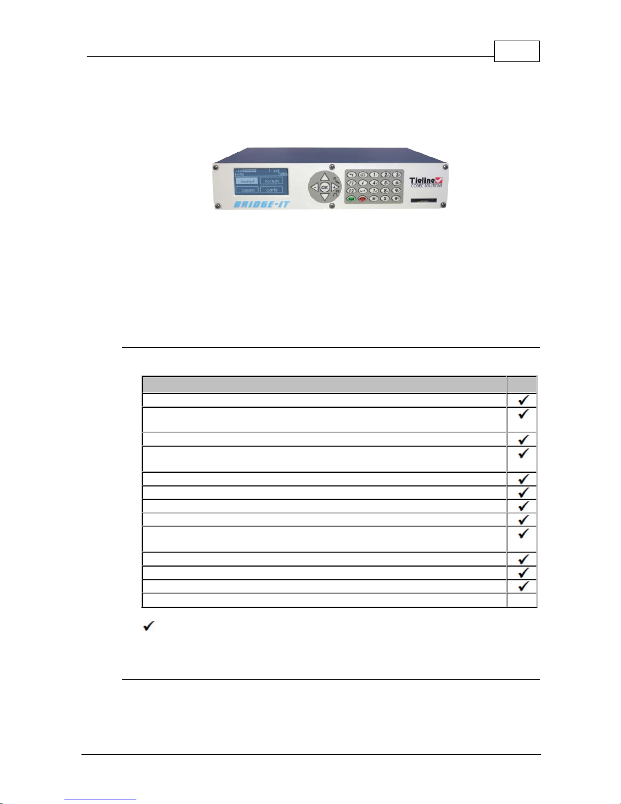
Welcome to Tieline’s Bridge-IT, the ultimate low-cost, high-performance, stereo IP audio codec
solution for broadcast and professional applications. Capable of both peer-to-peer or multi-point
connections, Bridge-IT transports audio streams reliably, simply and effectively over IP data
networks such as wired and wireless LANs, WANs, the internet, satellite IP, Wi-MAX and Wi-Fi.
Bridge-IT is perfect for a large range of broadcast and professional applications that include:
· Studio-to-Transmitter Link (STL) applications
· Stereo multi-unicast IP audio distribution (stereo to up to 6 endpoints)
· Simple remote broadcast links
· IP multicasts over compatible IP networks
· Low-latency audio over IP bridging solutions
· Multiple codec installations (2 codecs fit in 1 x 19” rack unit)
Codec Features
The following table outlines the features available in Bridge-IT.
Bridge-IT Features
Peer-to-pee r mon o and ste reo IP audio
SmartStream IP software for automatic management of IP connection
streaming
High quali t y low-delay linear au dio
G.711 G.722, MPEG Layer 2, p lus low-de lay Opus, Tieli ne Music and
MusicPLUS algorith ms
Simulta neou s an alog and d igital XLR AES/EBU outputs
A utomatic SD/SDHC card con nection f ailo ver
Web-GUI for remote control and configura t ion
EBU N/ACIP Tech 3326 compat ibil ity over IP
2 rel ay in puts and 2 opto-isolated ou t puts plu s RS-232 for local and remote
control of equipment at eit her en d of your codec li nk
Multi-un icast and send 6 stereo connection s, one with bidi rectional aud io
A AC-LD, AAC-ELD, LC-AAC, HE-AA C v . 1 and HE-AAC v.2 algorithms
TieServer for automatic firmware up grade notif ication
16 b it and 24 bit apt X® Enhanced algorithm
O
= includ ed
O = optio nal
Package Contents
Your codec is delivered with:
· Bridge-IT IP codec
Page 10

10 Bridge-IT M anua l
© Tieline Pty. Lt d. 2015
· Multi-region plug pack 12 volt 1 Amp power supply
· Phoenix 7-way connector for control port activation
If any of the parts are incorrect, missing, or damaged, contact Tieline or your nearest authorised
dealer.
Page 11
11
© Tieline Pty. Lt d. 2015
Bridge-IT M anua l
5 Front Panel Controls
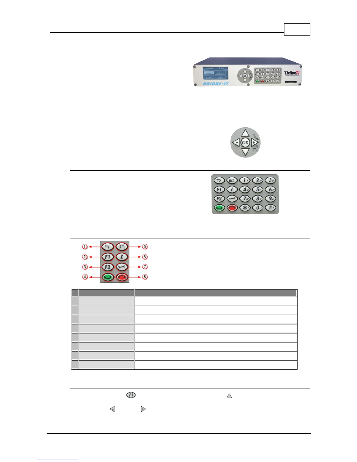
Bridge-IT features a full hardware front panel
interface with menu navigation buttons, an LCD
display with PPM metering and a dialing
keypad.
The codec also features an SDHC card slot,
which can be used for automatic program audio
backup, audio playout and in-store audio
recordings.
Navigation Buttons
Bridge-IT has four arrow shaped navigation
buttons for navigating codec menus and an
OK button for selecting menu items.
Dialing Keypad
The keypad has alpha-numeric buttons and
operation buttons used to:
· Launch codec functions.
· Navigate menus.
· Dial and hang up connections.
· Configure contact details.
Operati on Button Descri pti ons
Features
Operation Button De scriptions
1
Return Button
Press to navigate back through menus & delete characters
2
Function Button 1
Press to open codec user functions
3
Function Button 2
Press to open codec user functions
4
Connect Button
Press to dial IP connections
5
Home Button
Press to return to home screen
6
Information Button
Press to view a help menu on-screen
7
Settings Button
Press to configure codec settings
8
Hangup Button
Press to end a call
Adjusti ng LCD Screen Contrast Levels
1. Press and hold the button and then press the arrow up button to display the Contrast
adjustment screen.
2. Use the left and right arrow buttons to adjust the LCD screen contrast until viewing is
Page 12

12 Bridge-IT M anua l
© Tieline Pty. Lt d. 2015
optimised.
3. Press when you have finished.
Contrast can also be adjusted by pressing the HOME button, selecting Settings, then System,
and using the down button to navigate to Contrast.
Enabling and Disabling LCD Screen Auto Dim M ode
By default the codec LCD screen has Auto Dim mode enabled. This dims the intensity of the
display 30 secs after inactivity and is designed to maximise the working life of the screen. Disable
this mode if you want the screen to be illuminated at all times.
1. Press the HOME button to return to the Home screen.
2. Use the navigation buttons on the front panel to select Settings and press the button.
3. Nav igate to System and press the button.
4. Nav igate to Auto Dim and press the button to toggle between Enabled and Disabled.
Importa n t Note: Th e default Auto Dim t ime-out is reduced from 30 seconds to 10 seconds
when the Auto Lock function is enabled (to lock the front panel controls). Disabling Auto
Dim mode will override all ti me-out periods and the LCD will remain fully ill uminated at all
times.
Page 13
13
© Tieline Pty. Lt d. 2015
Bridge-IT M anua l
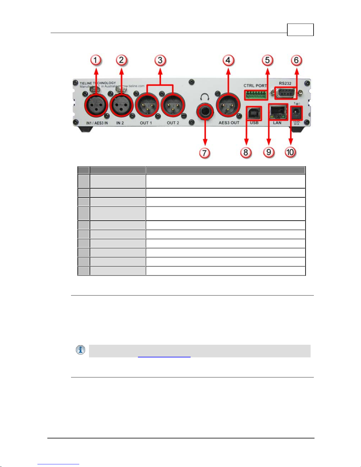
6 Rear Pane l Connec tions
Features
Rea r P anel Connection Descriptions
1
IN1/AES3 IN
Balanced Female XLR Mic/Line input 1 or AES3 (AES/EBU)
input for mono and stereo AES3 sources
2
IN 2
Balanced XLR Line input 2
3
Out 1/Out2
Balanced Male XLR Analog Line Outputs 1 and 2
4
AES3 OUT
AES3 (AES/EBU) output via male XLR for mono and stereo
AES3 signals
5
CTRL PORT
2 inputs/2 opto-isolated relay outs
6
RS232
RS-232 (DB9) connection for serial device control
7
Headphone Output
Stereo 6.35 mm (¼”) headphone out
8
USB 2.0 port
USB 2.0 for codec configuration
9
LAN
RJ-45 port for Ethernet 10/100 BaseT network connection
10
12v DC input
2.1mm 12V DC power supply connection
XLR Anal og and Digital I nputs
Bridge-IT features two XLR microphone inputs.
Input 1 is a balanced mic/line input with the ability to connect high, medium and low gain mics, as
well as an unbalanced source. It has switchable phantom power of 15 volts that is turned off by
default and can also be used as an AES3 (AES/EBU) digital input. This input accepts both mono
and stereo digital AES3 signals. Input 2 is a line input only.
Important Note: Channel 2 input gain can only be adjusted using the Inp ut Audio screen
on the codec (See: Adjusting Input Levels)
XLR Anal og and AES3 Outputs
Bridge-IT features two balanced XLR analog audio outputs and a digital XLR AES3 (AES/EBU) audio
output. Both the analog and digital outputs can be used simultaneously and the AES3 output can
send both mono and stereo signals via the single XLR output.
Page 14

14 Bridge-IT M anua l
© Tieline Pty. Lt d. 2015
Stereo Headphone Jack Output
Bridge-IT has a 6.35mm (1/4") stereo headphone output jack for monitoring audio inputs 1 and 2 and
return link audio. Channel 1 is mapped directly to the left headphone output and channel 2 is
mapped directly to the right headphone output. When listening to return link audio channel 1 is
mapped directly to the left headphone output and channel 2 is mapped directly to the right
headphone output. (See Headphone Monitoring)
LAN Port
The codec features a RJ-45 port for Ethernet 10/100 BaseT network connections.
Command & Control Interf aces
Bridge-IT features:
1. 2 relay inputs and 2 opto-isolated outputs for machine control via the CTRL PORT.
2. A nine pin RS-232 connection for local and remote control of equipment at either end of the
link
3. A USB 2.0 (slave) connection for codec web-GUI configuration.
DC Power Input
The codec is powered by a 12 volt DC power supply using a standard polarised DC plug.
Page 15
15
© Tieline Pty. Lt d. 2015
Bridge-IT M anua l
7 Navigating Codec Menus
The codec has simple and intuitive menu navigation screens. All main codec menus can be
launched from the Home screen and audio levels remain visible throughout all menus.
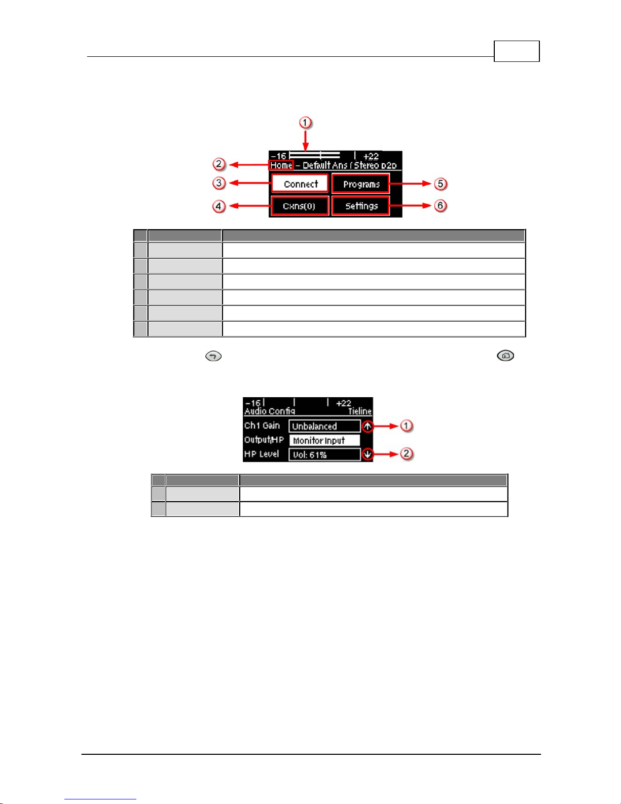
Bridge-IT Hom e Screen
Features
Codec Home S cre en Elem ents
1
PPM Meters
Left (top) and right channel audio levels
2
Screen Name
The name of the current screen being navigated
3
Connect
Select to dial & adjust connection settings
4
Cxns
Displays the number of current connections
5
Programs
View and edit Program dialing configurations
6
Settings
Select to configure codec settings
Press the RETURN button to navigate backwards through menus, or press the HOME
button to return to the Home sc reen from any menu. If a full menu cannot be viewed on the codec
sc reen then arrows on the right hand side of the screen indicate that the current menu has items
below and/or above t he items c urrently visible. Use the navigation arrows t o scroll up and down.
Features
Codec Home S cre en Elem ents
1
Up Arrow
Arrow indicating menus can scroll upwards
2
Down Arrow
Arrow indicating menus can scroll downwards
Page 16
16 Bridge-IT M anua l
© Tieline Pty. Lt d. 2015
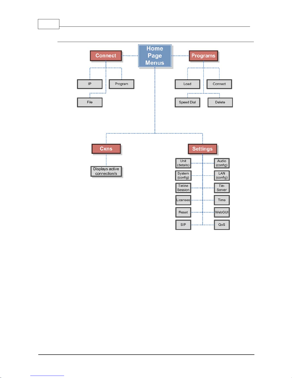
Codec Menu Overview
Page 17
17
© Tieline Pty. Lt d. 2015
Bridge-IT M anua l
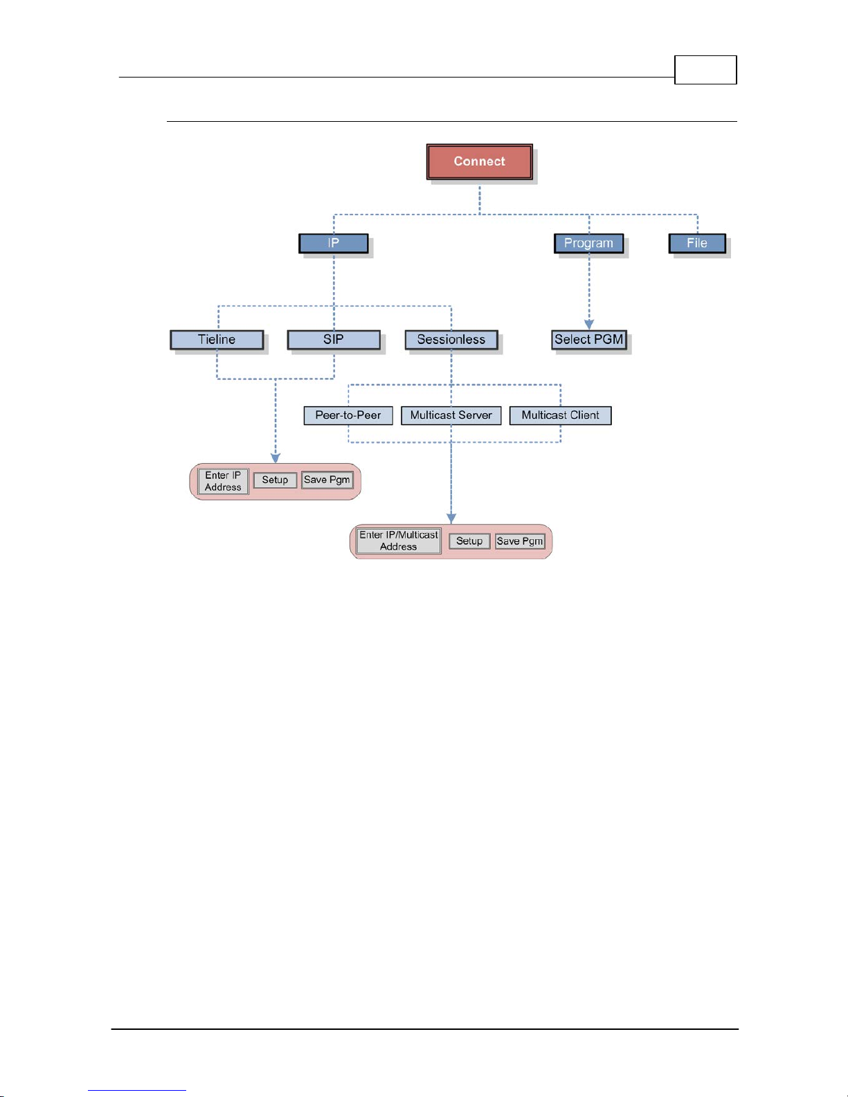
Connect Menu
Page 18

18 Bridge-IT M anua l
© Tieline Pty. Lt d. 2015
IP Setup Menu Navigati on
Page 19

19
© Tieline Pty. Lt d. 2015
Bridge-IT M anua l
Settings Menu
Page 20
20 Bridge-IT M anua l
© Tieline Pty. Lt d. 2015
8 Adjusting Input/Meter Leve ls
The codec uses dBu to express nominal operating level, headroom and noise floor levels. The PPM
meters display input audio by default when the codec is not connected and they then switch to
monitor decoded return program audio after making a connection.
Mono and Stereo Audio Capabilit i es
The codec sends input 1 directly to the left output and input 2 directly to the right output. When
sending mono analog audio select a mono algorithm in the IP Connect Setup menu and connect
audio to input 1 of the codec. Input audio is replicated and sent to both channel 1 and 2 analog XLR
outputs in this mode. The AES3 outputs are directly mapped to both the analog and digital inputs,
therefore if a mono analog profile is selected, only channel one will have audio on it over AES3.
Note: It is not possible to mix channels 1 and 2 into dual mono outputs.
The codec will provide both analog and digital audio out at all times and this is not dependent on
whether your audio source is analog or digital. The only point to note is that when you configure a
mono analog connection the codec will only send audio on one of the AES3 outputs, but it will send
audio on both the left and right channels of the analog outputs.
Adjusti ng Audio M eter Reference Scale Settings
When connected to stereo sources the top PPM meter is the left channel and the bottom PPM
meter is the right channel. The codec is configured by default to automatically connect to other
Tieline codecs using the correct audio reference meter scales. The audio reference level settings in
the codec are:
Reference S etting
Description
1
Auto (default)
When connecting to a Tieline codec with session data enabled
the codec will automatically adjust the reference level for G5 and
G3 codecs. When connecting to a non-Tieline codec, or a Tieline
codec without session data enabled, the codec will use the
Tieline G5 setting.
2
Tieline G5
The audio reference scale is -16dBu to +22dBu
3
Tieline G3
The audio reference scale is -11dBu and +18dBu
To configure this setting manually:
1. Press the SETTINGS button.
2. Navigate to Audio and press .
3. Navigate to Ref Level and press .
4. Select the preferred setting and press .
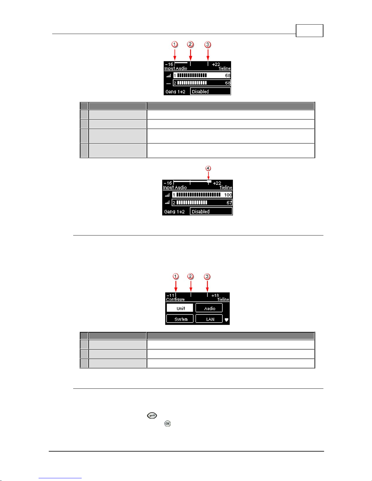
Audio Meteri ng when Connecti ng to Tieli ne G5 Codecs
The Tieline G5 audio reference scale displayed on the codec screen is -16dBu to +22dBu when
you connect to a codec in Tieline's Merlin, Genie or Bridge-IT IP codec families. Set audio levels so
that audio peaks average at the nominal 0vu point. This represents a program level of +4 dBu leaving
the codec. Audio peaks can safely reach +22 dBu without clipping, providing 18dBu of headroom
from the nominal 0vu point. The default PPM audio meter indications are as follows.
Page 21
21
© Tieline Pty. Lt d. 2015
Bridge-IT M anua l
Features
Description
1
-16dBu
PPM meter low point
2
+4dBu
Nominal 0vu reference level at +4dBu
3
+20dBu
+20dBu indication that should not be exceeded to prevent clipping
at +22dBu
4
PPM meter in clip
PPM indication displays a solid section at the right-hand end
when audio is in danger of clipping
Audio Meter i ng when Connecting to Tieline G3 Codecs
New generation Genie, Merlin and Bridge-IT IP codecs have more audio headroom than Tieline G3
audio codecs, therefore metering needs to be adjusted when connecting to a Commander or i-Mix
G3 codec. The G3 metering scale is between -11dBu and +18dBu and audio levels should average
around the nominal 0vu point. Audio peaks should not exceed +16dbu as indicated on the PPM
meter.
Features
Description
1
-11dBu
PPM meter low point
2
+4dBu
Nominal 0vu reference level at +4dBu
3
+16dBu
+16 indication where audio will clip/distort
Channel 1 Mi c/ Line Level A udio Adj ustment
The default input level setting in the codec for channel 1 is line level. To adjust this setting for a miclevel or unbalanced source:
1. Press the SETTINGS button.
2. Navigate to Audio and press .
Page 22
22 Bridge-IT M anua l
© Tieline Pty. Lt d. 2015
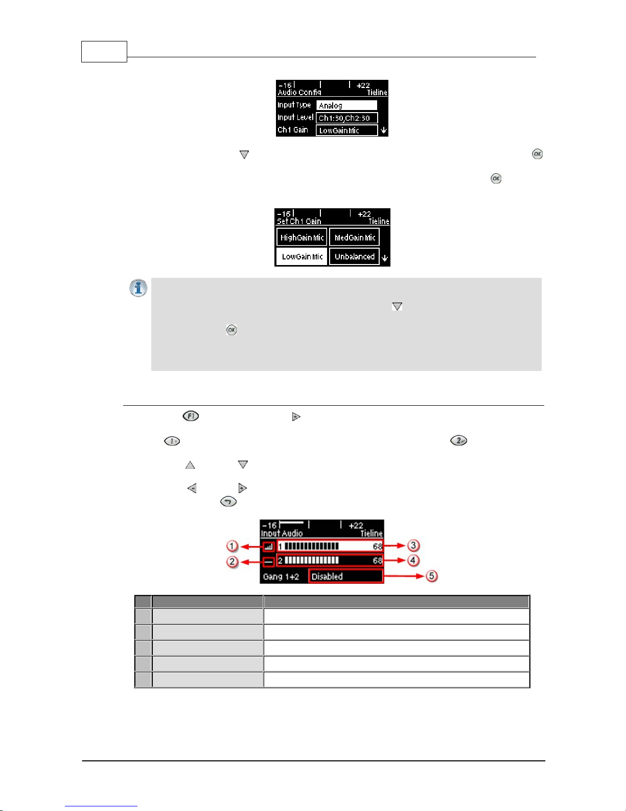
3. Ensure Input Type is set to Analog.
4. Use the arrow-down button to highlight and select the Ch 1 Gain setting and press the
button.
5. Use the navigation buttons to select the appropriate gain setting and press the button to
save the setting.
Importa n t Note: 15 volt phantom power is not s upplied to input 1 by default . To turn this on:
1. Select Settings > Audio and use the arrow-down button to highlight the Phantom
setting.
2. Press the button to toggle between Enabled and Disabled.
Channel 2 is a line input only and gain can only be adjusted using the In put Audio screen
on the codec.
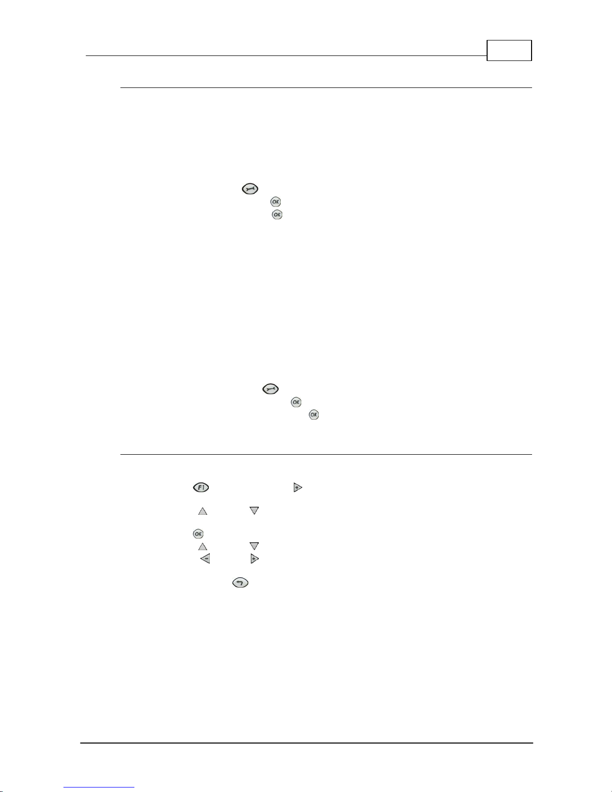
Quick A djustm ent of I nput Levels
1. Press the button and the right arrow button to open the Input Audio level adjustment
screen.
2. Press on the numeric keypad to toggle channel 1 on and off and press to toggle channel
2 on and off.
3. Use the up and down arrow buttons to navigate to the channel you want to adjust. Note: A
channel is highlighted when selected.
4. Use the left and right arrow buttons to adjust the input levels up or down.
5. Press the RETURN button to exit t he sc reen.
Input Audio Fe atures
Description
1
Channel On Symbol
Symbol indicates a channel is turned on
2
Channel Off S y m bol
Symbol indicates a channel is turned off
3
Input 1 Level Control
Ch 1 level indication with percentage of gain indicated, i.e. 68.
4
Inp ut 2 Level Contro l
Ch 1 level indication with percentage of gain indicated, i.e. 68
5
Ch1/2 Gang Indication
Indicates whether ganging is enabled or disabled
Page 23
23
© Tieline Pty. Lt d. 2015
Bridge-IT M anua l
Intell i gent G ai n Control (I G C)
When the broadcast action really starts to heat up, the codec's inbuilt DSP limiter automatically
takes care of any instantaneous audio peaks that occur in demanding broadcast situations. IGC
(Intelligent Gain Control) is enabled by default and is activated at +20 dBu (G5 audio scale) and
+14dBu (G3 audio scale) to prevent audio clipping. IGC automatically adjusts high audio input levels
downwards until they are acceptable. If IGC auto level recovery (IGC Level) is not enabled, the input
level will remain at the adjusted point until the input gain is manually adjusted again by the user. If
IGC is active in the codec it is indicated in the PPM meter section. To adjust this setting:
1. Press the SETTINGS button.
2. Navigate to Audio and press .
3. Navigate to IGC and press to toggle between Enabled and Disabled.
IGC A uto Level Recovery
IGC Level works with IGC to detect when incoming audio levels have reduced sufficiently.
There are two settings; Auto and Fixed.
If the IGC Level setting is Auto then the codec will return input levels to the gain setting prior
to IGC being activated. The codec takes just 250 milliseconds to detect audio levels have
returned to normal (after IGC Level has been initiated) and will then return the levels to the
previous setting within half a second. This response is linear.
If the setting is Fixed then audio levels will remain lower and not return to the original setting.
To adjust this setting:
1. Press the SETTINGS button.
2. Navigate to Audio and press .
3. Navigate to IGC Level and press to toggle between Auto and Fixed.
Ganging Audio Channels
Ganging allows you to adjust the audio level of both inputs simultaneously.
1. Press the button and the right arrow button to open the Input Audio level adjustment
screen.
2. Use the up and down arrow buttons to navigate to and select Gang 1 + 2 Enabled or
Disabled.
3. Press the button to select Enabled.
4. Use the up and down arrow buttons to highlight and select the audio channels.
5. Use the left and right arrow buttons to adjust t he levels for both inputs up or down
simultaneously.
6. Press the RETURN button to exit t he sc reen.
When channels 1 and 2 are ganged together:
· Both channels highlight together when selected.
· You can adjust the audio of both channels simultaneously.
· The gain setting for both channels is automatically set to match the gain level of the lowest of
the two channels when ganging is configured.
· If one channel is turned on when ganging is configured then the other one will be turned on
automatically.
Page 24
24 Bridge-IT M anua l
© Tieline Pty. Lt d. 2015
9 Configuring AES3 Audio
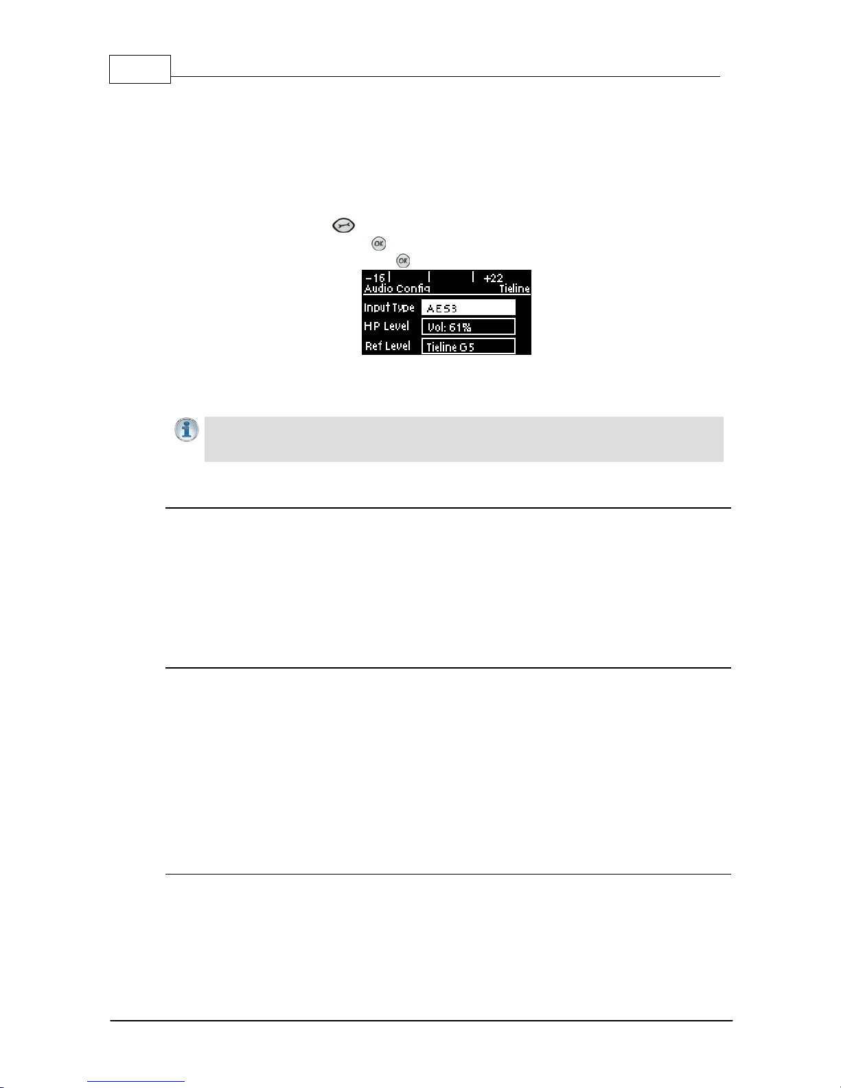
If your input source is AES3 (AES/EBU) format use the IN1/AES3 IN input on the rear panel of the
codec. This is a balanced 110 ohm female XLR input and can operate effectively over distances of up
to 100 meters. The input accepts both mono and stereo AES3 signals as only a s ingle 3 pin XLR
input or output is required for sending and receivi ng two channels of AES 3 data. To configure the
codec to acc ept A E S3 data si gnals:
1. Press the SETTINGS button.
2. Navigate to Audio and press .
3. Select Input Type and press the button to toggle from Analog to AES/EBU.
The 3 pin male XLR AES3 output on the rear panel is labeled AES3 OUT. It is capable of sending
both mono and stereo AES3 signals.
Importa n t Note: Input levels are set at 100% automatically for AES3 c onnections. If you
switc h back t o the analog input set t ing after selecting AES3, t he previous analog settings
will be recov ered .
AES/EBU Sample Rate Conversi on
The codec implements an Asynchronous Sample Rate Converter (ASRC) to convert the sample rate
of the AES3 input to the sample rate set in the codec. The codec sample rate is determined by the
selected algorithm. For example, if you select the Music algorithm, the sample rate will be set to
32kHz when the codec is connected.
The codec accepts AES3 input sample rates of 32kHz, 44.1kHz or 48kHz. The output sample rate
is determined by the algorithm used when connected.
AES3 Audio Out & SD Card Sample Rate
1. When you are not connected, you can adjust the AES3 output sample rate manually in the
Audio menu via the AES3 SR setting.
2. If file playback occurs before a connection is initiated, the AES3 output sample rate will match
the audio file sample rate.
3. For best performance, the SD card file sample rate should match the AES3 SR setting in the
codec and the algorithm sample rate. If they don't match, the codec will re-sample the SD card
file audio to match the connection sample rate, and this will be used by the AES3 output. For
example, if you are streaming audio using Tieline Music (32kHz sampling), file playback will be
re-sampled to 32kHz if the SD card file is 44.1kHz or 48kHz. In this example the AES3 output
sample rate will be 32kHz.
Adjusti ng the Codec Output Sample Rate
As there is no external reference clock for the codec it is necessary to set the output sample rate of
the codec when you are not connected. The AES3 SR setting in the Audio menu will configure
audio outputs and audio monitoring, as well as SD card playback at this sample rate. The default
setting is 48kHz sampling:
Page 25

25
© Tieline Pty. Lt d. 2015
Bridge-IT M anua l
1. Press the SETTINGS button.
2. Navigate to Audio and press .
3. Navigate to AES3 SR and press .
4. Select a preferred sample rate then press .
Tieline normally recommends selecting STL Silence Mode for audio monitoring if using AES3. If
using Auto Select make sure the algorithm sample rate and the AES3 SR sample rate setting are
the same.
Page 26
26 Bridge-IT M anua l
© Tieline Pty. Lt d. 2015
10 Headp h o n e/Output Monitoring
The 6.35mm (1/4") stereo headphone output on the codec c an be used for monitoring audio inputs 1
and 2 and return link audio .
Importa n t Note: When the codec makes a connection it will monitor the decoded return
audio link by default.
Adjusti ng Headphone Output Levels
When using analog or digital inputs y ou will see input audio on the PPMs and hear it in the
headphones.
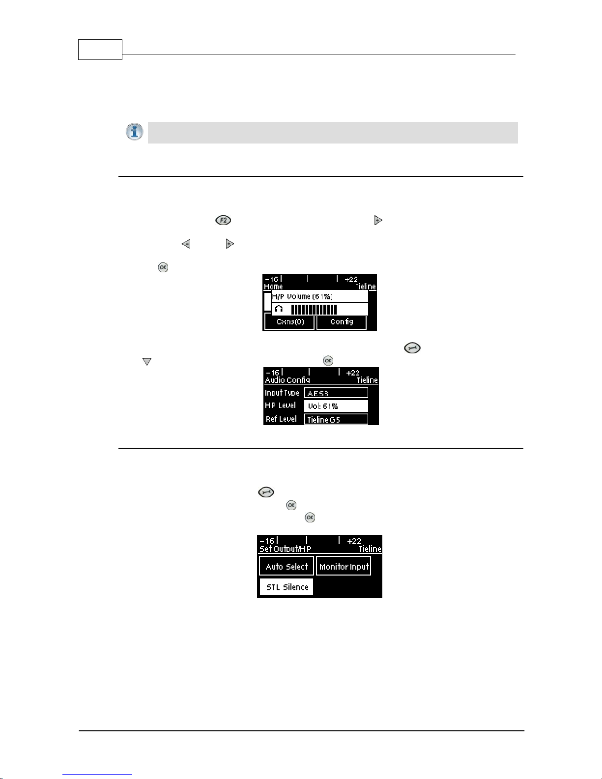
1. Press and hold the button and then press the right arrow button to display the H/P
Volume adjustment screen.
2. Use the left or right navigation buttons to adjust the volume levels up or down. The screen
displays level adjustments in real-time.
3. Press when you have finished.
Headphone levels can also be adjusted by navigating to SETTINGS > Audio and using the
down button to navigate to HP Level and press .
Output/Headphone Monit ori ng Settings
There are three Output/HP monitoring configurations available in the codec. The default setting is
Auto Select and to adjust this setting:
1. Press the SETTINGS button.
2. Navigate to Audio and press .
3. Navigate to Output/HP and press to select either Monitor Input or STL Silence.
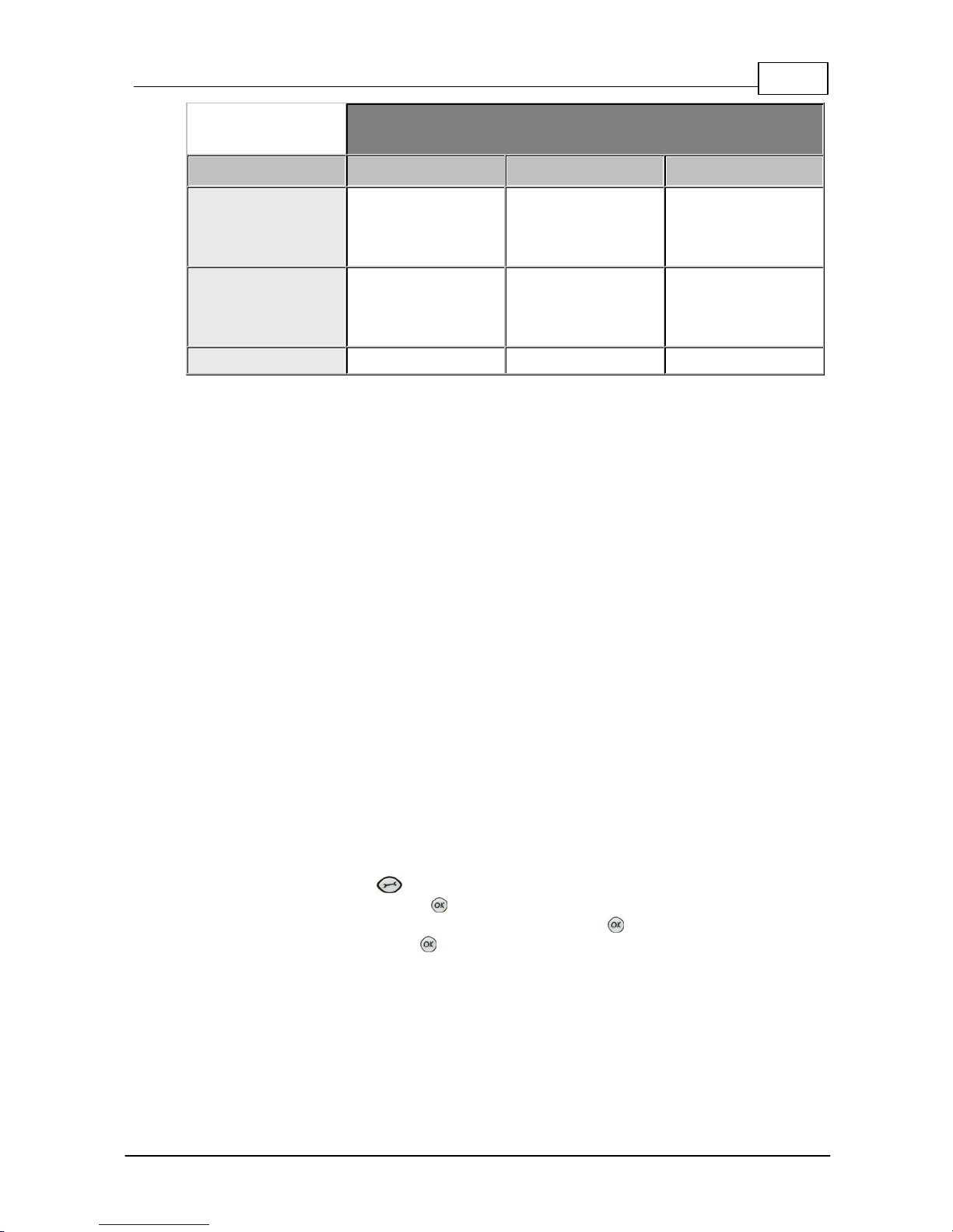
The table below displays how audio is routed to the codec outputs/headphones based on the
configuration selected and the current codec state (IP streaming or idle). Please note:
· The same audio is always routed to the headphone and XLR outputs.
· Output 1 corresponds to headphone left and output 2 corresponds headphone right.
· The same audio is routed to the analog and AES XLR outputs.
· When inputs are routed to the outputs, input 1 is sent to output 1 and input 2 is sent to output
2.
Page 27
27
© Tieline Pty. Lt d. 2015
Bridge-IT M anua l
Codec Connection S ta te
Mode
Idle
Streami ng (Mono)
Streami ng (Ste reo)
Auto Select
(default)
Inputs
Same decoded audio
on all outputs
Channel 1 decoded
on output 1, and
channel 2 decoded on
output 2
STL Silence
No audio
Same decoded audio
on all outputs
Channel 1 decoded
on output 1, and
channel 2 decoded on
output 2
Monitor Input
Inputs
Inputs
Inputs
Auto Select M ode
Auto Select is the default Output/HP monitoring setting in the codec. Use this setting if you
want to monitor the inputs when not connected and return audio when connected.
Monitor I nput Mode
Select Monitor Input to configure the codec to always monitor input audio. This may be useful
if an announcer wants to monitor their own voice and not return audio when connected.
STL Sil ence Mode
1. In STL Silence mode input audio is not monitored on the PPMs or via the headphone output
before the codec is connected. It is necessary to check input audio levels using Auto Select
or Monitor Input modes prior to connecting.
2. When the codec connects in STL Silence mode it automatically monitors decoded incoming
audio.
3. If the connection is lost for any reason then silence is enabled, ensuring input audio cannot
be misconstrued as return program audio for STL connections.
4. If the connection is subsequently restored the codec will again monitor decoded incoming
audio.
11 Langu age Selection
English is t he default language in the codec. To adjust t his setting:
1. Press the SETTINGS button.
2. Navigate to System and press .
3. Use the navigation buttons to select Language and press .
4. Select a language and press .
Page 28

28 Bridge-IT M anua l
© Tieline Pty. Lt d. 2015
12 About Program Dialin g
What Defines a Program?
The codec uses the concept of 'program' dialing to connect using peer-to-peer, multicast or multiunicast connections. A Program configures a Tieline codec to send or receive an Audio Stream.
The attributes of each audio stream and associated connections are embodied within a program
when it is created, including the configuration, dialing and answering parameters. Essentially a
program is like a connection profile with:
· A Program Name.
· IP address dialing details for up to 6 connection end-points or a multicast IP address.
· Specific connection profile details pertaining to algorithm, FEC, jitter buffer and bit-rate
settings etc.
Custom programs allow you to store connection settings for a range of peer-to-peer, multicast and
multi-unicast connections and retrieve or edit them easily at the touch of a button. Simple peer-topeer or multicast profiles can be created using the codec front panel, whereas multi-unicasts must
be created with the Programs panel in the Toolbox web-GUI.
Using Programs to Dial between Two Tieli ne Codecs
Tieline Bridge-IT and Bridge-IT XTRA codecs operate similarly to Tieline G3 codecs. By default,
Tieline codecs send proprietary session data when connecting to each other in order to establish,
manage and terminate connections. When a connection between two codecs is established:
1. The dialing codec sends information about how the codec receiving the call should be
configured.
2. Once the codec receiving session data from the dialing codec has received information
successfully, it sends an acknowledgement to the dialing codec and streaming can
commence.
If you configure a stereo program on the dialing codec using a particular algorithm and bit rate etc.,
these settings will be configured on the answering codec when it connects. It is also possible to
lock a loaded program in a codec to ensure the currently loaded program cannot be unloaded by a
codec dialing in with different program settings.
Creating Programs
Simple peer-to-peer (point-to-point) programs can be created using the codec front panel. The
Toolbox web-GUI contains a Programs panel with a wizard for configuring program settings and
backup connections. Edit settings easily at the touch of a button and use existing programs as
templates for creating other programs.
Mono and Stereo Peer-to-Peer Programs
New peer-to-peer programs can be created using the codec front panel keypad (see 10 Quick
Steps to Connect). If you know the IP address of the codec you want to dial then all you need to
do is enter this into the codec, choose your preferred connection settings and then press
CONNECT .
Front panel configured programs are automatically saved as Recent Programs which retain all
the audio stream dialing and configuration information. These Recent Programs are displayed
when you press the CONNECT button from within any menu except the IP Mode or SIP
Mode screens, or the Connect IP or Connect SIP screens.
Page 29

29
© Tieline Pty. Lt d. 2015
Bridge-IT M anua l
Ensure you configure all the correct connection settings when using the codec front panel,
because these are stored as part of the program's profile when you first connect. They cannot
be adjusted afterwards without using the editing features in the Program panel within the
Toolbox web-GUI.
Importa n t Note: When configuring a connection use the Save function in the Conne ct IP
and Connect SIP screens to save programs permanen tly to the codec's Programs menu.
Otherwise they are stored to the Rece n t Programs list and will be overwritten after several
calls have been made.
Multi - unicast Programs:
Multi-unicast programs can contain dialing information for up to 6 connection end-points. They
are useful for distributing audio to several studios and can be created using the Programs
panel in the Toolbox web-GUI. (See Configuring Multi-Unicast Programs for configuration
details). Once multi-unicast connections have been created they can be dialed via the codec
keypad without using the web-GUI.
Multi cast Programs:
Multicasts can be used to broadcast to 'subscribers' who wish to connect to a multicast stream.
Multicast server transmissions are sent using a dedicated IP multicast address that looks
similar to a regular IP address and multicast (client) subscribers request transmissions from
this address. New programs can be created using either the codec front panel or the Programs
panel in the Toolbox web-GUI. (For web-GUI configuration see Configuring a Multicast Server
Program or Configuring a Multicast Client Program).
Page 30
30 Bridge-IT M anua l
© Tieline Pty. Lt d. 2015
13 Getting Connected Quickly
Preparing to Connect
Before attempting a new connection please connect and adjust the following:
1. Attach the supplied 12 volt power supply to the codec.
2. Attach an RJ45 Ethernet cable to the LAN port on the rear panel of the codec.
3. Attach headphones to the 6.35mm (1/4") headphone jack on the rear panel of the codec.
4. Check that the correct country is selected in the codec.
i. Press the SETTINGS button.
ii. Navigate to System and press the button.
iii.Navigate to Country and press the button.
iv. Use the navigation buttons to select your country of operation.
5. Make sure you have the IP address of the codec you are dialing, or have used the Toolbox
web-GUI to load the programs you will be using to dial onto the codec. (see Configuring IP
Addresses).
13.1 10 Quick Steps to Connect Bridge-IT
Important Notes:
· The following procedure will create a custom peer-to-peer connection program using the
codec front panel keypad and navigation buttons. It instructs how to connect your codec
over IP for the very first time without using the Toolbox web-GUI and your computer for
configuration.
· See the Java Toolbox Web-GUI Introduction for details on configuring connections
remotely via a computer. Creation of programs is not currently supported in the HTML5
Toolbox Web-GUI.
· See Installing the Codec at the Studio for valuable information about installing your
codec, negotiating firewalls and port forwarding.
· See Tips for Creating Reliable IP Connections for a range of IP information to assist with
setting up IP services for your codecs.
· See Testing IP Network Connections to learn how you can test and verify the reliability of
your IP connection.
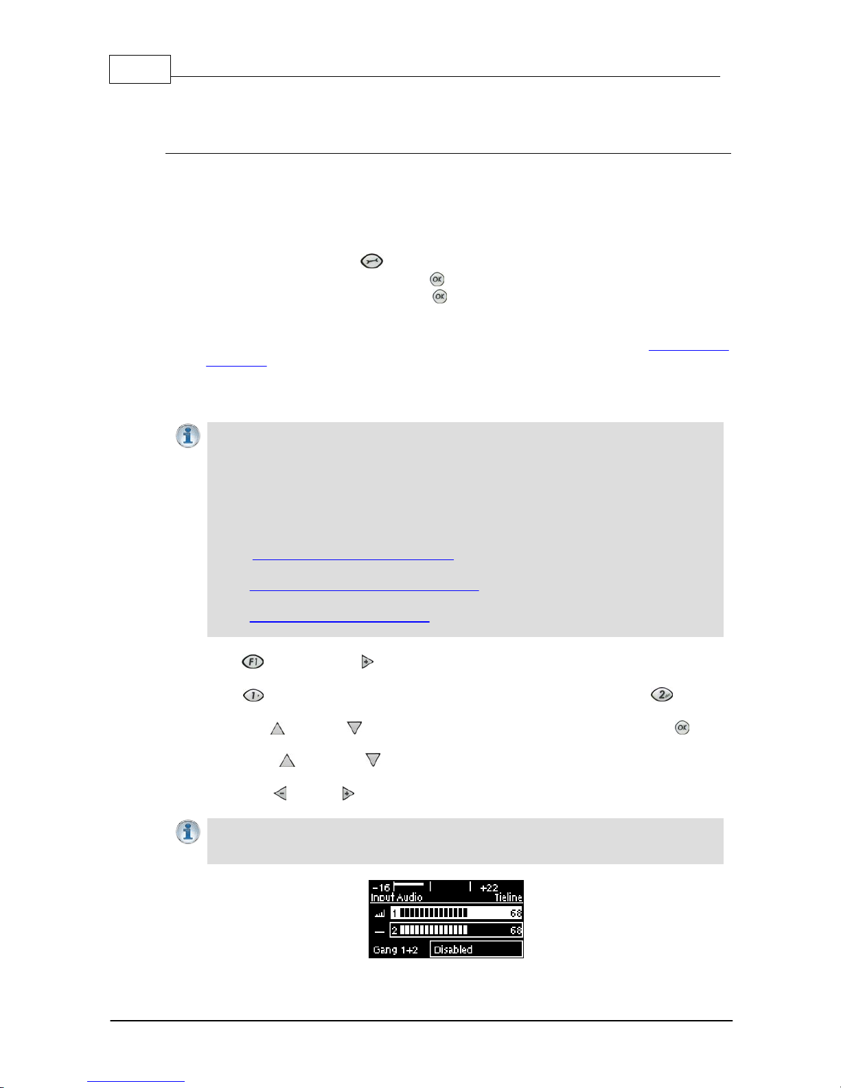
1. Press the button and right navigation button to open the Input Audio Level adjustment
screen and adjust audio levels.
· Press on the numeric KEYPAD to toggle channel 1 on and off and press to toggle
channel 2 on and off.
· Use the up and down navigation buttons to select Gang 1 + 2 and press the button
to toggle ganging on/off.
· Use the up and down navigation buttons to select a single channel, or ganged
channels. Note: A channel is highlighted when selected.
· Use the left and right navigation buttons to adjust the input levels up or down.
Important Note: 15 volt phantom power is not supplied to input 1 by default. To adjust this
setting select Settings, then Audio and then Phantom. Press the OK button to toggle
between Disabled and Enabled.
Page 31
31
© Tieline Pty. Lt d. 2015
Bridge-IT M anua l
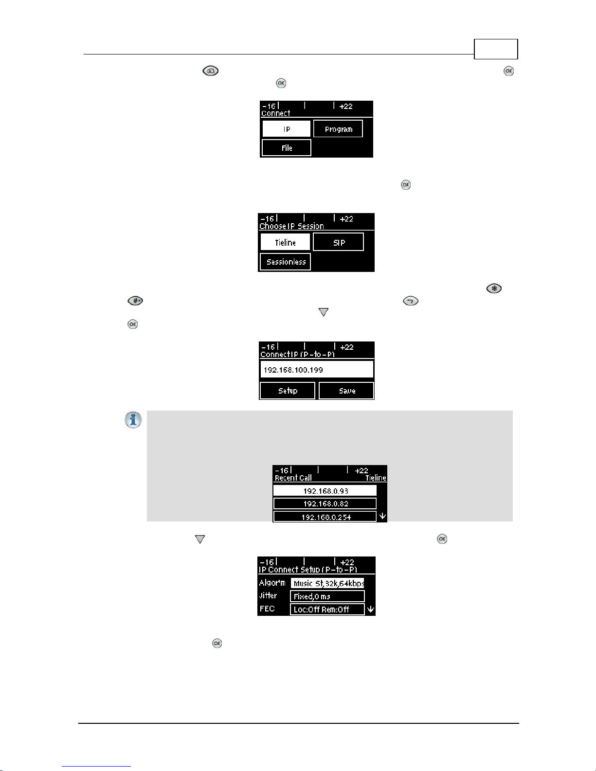
2. Press the HOME button to return to the Home screen, select Connect and press the
button, then select IP and press the button.
3. Select your preferred IP Session mode. In this Peer-to-Peer connection example we have
selected Tieline, which uses Tieline session data, then press the button. Note: Select SIP
or Sessionless if these connections are required.
4. Use the numeric KEYPAD to enter the IP address of the codec you want to dial, using t he or
buttons to enter the periods in the IP address. Use the RETURN button to delete
number s alread y entered. Next, press the down navigation button to select Setup and press
.
Important Note: The codec remembers recent IP addresses just like a cell-phone. To
view these addresses just press the OK button when you select the Connect IP screen.
The most recent addresses and programs are listed first and you can use the navigation
buttons to scroll up and down. Press the OK button to select the address you have
highlighted.
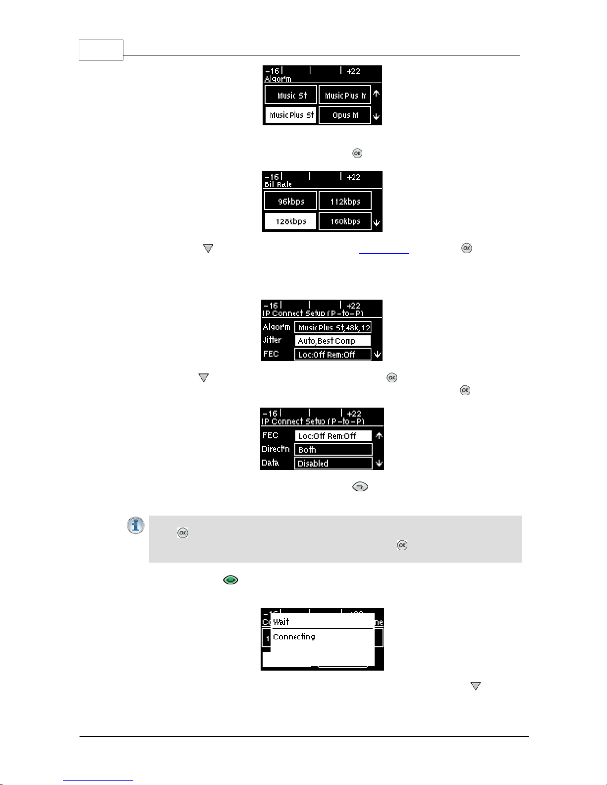
4. Press the down navigation button to select Algor'm (algorithm) and press .
5. Use the navigation buttons to select a preconfigured algorithm profile, or manually enter algorithm
settings, then press .
Page 32
32 Bridge-IT M anua l
© Tieline Pty. Lt d. 2015
6. If you decide to manually configure the algorithm, use the navigation buttons to select your
preferred sample rate (if displayed) and bit rate. Press after selecting each option.
7. Press the down navigation button to select Jitter (jitter buffer) and press to select a
different automatic jitter buffer setting for your connection. Alternatively you can enter a fixed jitter
buffer value in milliseconds (maximum 5000 ms). The default Auto, Best Compromise setting is
a good starting point for most internet connections.
8. Press the down navigation button to select FEC and press to view selection options. Use
the navigation buttons to choose the FEC percentage you want to use and press .
9. When configuration is complete press the RETURN button to navigate backwards to the
Connect IP screen that the IP address was entered into.
Importa n t Note: At this point you can navigate to Save on the Connect IP screen and
press t o s ave the setti ngs as a c us t om program for subsequent recall and dialing. Use
the numeric KEYPAD to give the prog ram a name and press to save the program. A
confirmation message is displayed after the program is s aved.
10.Press the CONNECT button to make a connection. The Wait Connecting screen appears
during the connection process.
After successfully connecting the codec will display connection details. Use the down navigation
Page 33
33
© Tieline Pty. Lt d. 2015
Bridge-IT M anua l
button to view connection Status and press to view connection statistics for IP packets being
sent over the connection. To negotiate higher bit-rates press then 3 on the numeric KEYPAD;
for lower bit-rates press then 9.
13.2 Monitoring IP Connections
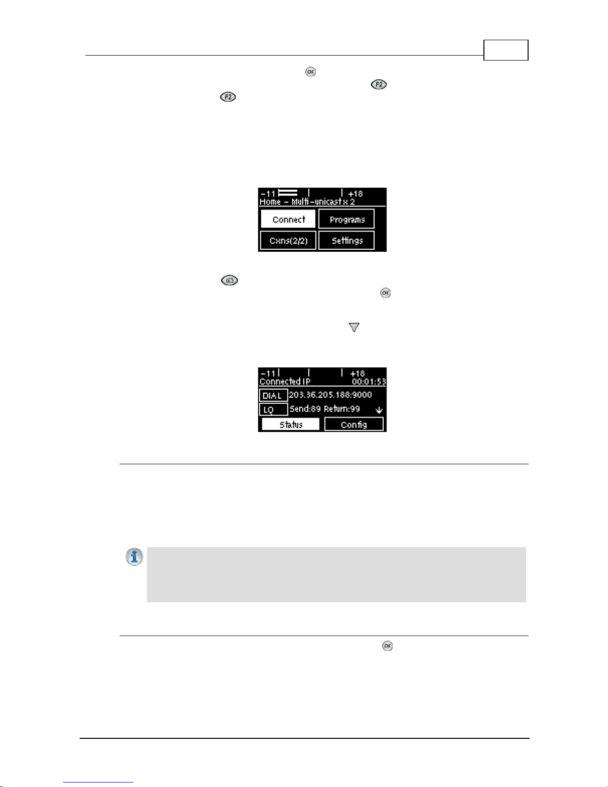
The number of active audio streams and connections is displayed on the Home screen via Cxns. In
the following image the program has two connections configured and both are active, expressed as
2/2. If only one was active the bracketed number would display 1/2.
To view more detailed connection information:
1. Press the HOME button to return to the Home screen.
2. Use the navigation buttons to select Cxns and press the button.
The Connected IP screen displays all connections. The IP address dialed and the LQ (link quality)
is displayed on the screen and you can use the down navigation button to view the algorithm
being used, the connection bit rate, total bytes used and the jitter buffer latency over IP network
connections.
Link Qualit y ( LQ) Readings
Send and return LQ numbers can also help to determine if a problem is occurring at either end of a
connection. For example, on an IP connection the Return reading represents the audio being
downloaded from the network locally (i.e. audio data is being sent by the remote codec).
Conversely, the Send link quality reading represents the audio data being sent by the local codec
(i.e. being downloaded by the remote codec). To ensure a stable connection, try to maintain a
reliable reading of 80 or higher for both the Send and Return LQ reading.
Importa n t Note:
· The Return link quality reading is the same as the Local (L) setti ng displayed on a G3
codec.
· The Send link quality reading is the same as the Remote (R) sett ing displayed on a G3
codec.
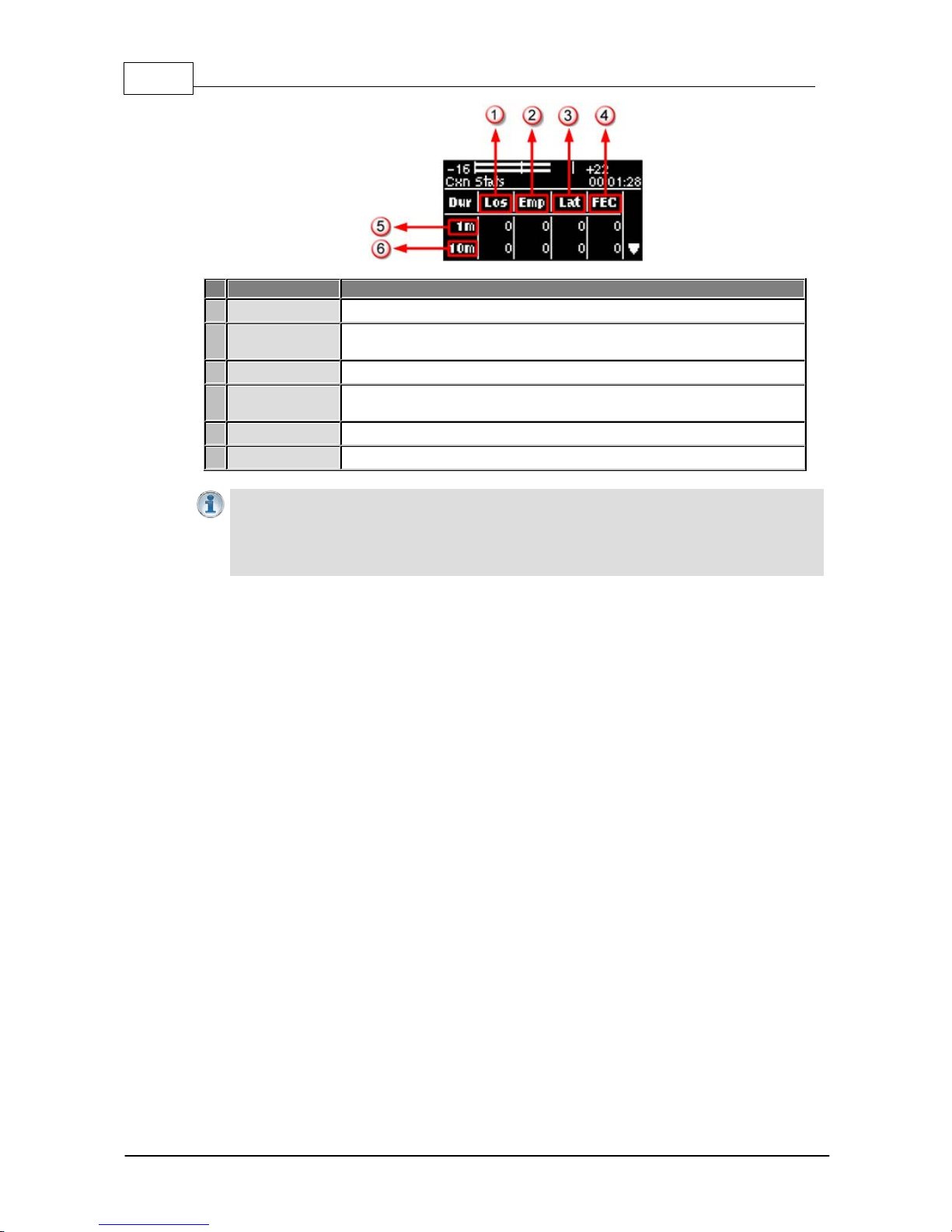
Viewing Connection Statisti cs
Navigate to Status in the Connected IP screen and press the button to display the Cxn Stats
(connection statistics) screen. This displays the performance of the codec in sending IP audio
packets across the network. Analysis is historic and assessed over 60 seconds and 10 minutes of
connection time.
Page 34
34 Bridge-IT M anua l
© Tieline Pty. Lt d. 2015
Feature
Description
1
Lost Packets
Packets sent that failed to arrive
2
Empty (Jitter
Buffer)
Indicates how often the jitter buffer ‘reservoir’ empties causing loss of
audio
3
Late Packets
The number of packets that arrive late, i.e. after audio play out
4
FEC Packets
Indicates the number of forward error correction (FEC) packets that
have been sent if it is enabled in the codec
5
1 minute
Statistics listed for the last minute of network activity
6
10 minutes
Statistics for the last 10 minutes of network activity
Importa n t Note: If the jitt er buffer, FEC or the connection bit rate is c hanged, we
recommend assessi ng a minute of recent connection performance in preference to 10
minutes of historical connection performance. 10 minutes of data will include connection
sett ings which may no longer be relevant. ‘Pac k et arrival his t ory’ i s c leared when you hang
up a connect ion.
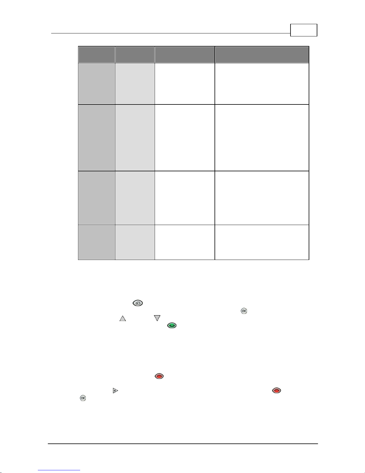
Following is an analysis of possible causes and solutions for the packet analysis statistics
displayed on the screen.
Page 35
35
© Tieline Pty. Lt d. 2015
Bridge-IT M anua l
Packet
Analysis
Displays
Possibl e Causes
Possibl e Solu tions
Loss
Packets sent
and that failed
to arrive.
· LAN/WAN congestion
· Unreliable ISPs
· Unreliable networks
· Inferior IP hardware
· Renegotiate connection bit rate
downwards
· If link quality good add or increase
FEC as required
· Assess ISP’s QOS if very bad
performance
Empty
Indicates how
often the jitter
buffer
‘reservoir’
empties
causing loss
of audio.
· High number of
packets being lost or
arriving late
· Signal drop-outs
using cell-phone
networks
· Renegotiation
causes the jitter
buffer reservoir to
empty
· Once could be an anomaly –
assess lost & late packets
· If many lost packets network is
unreliable – renegotiate bit rate
and /or FEC down
· If many late packets increase jitter
buffer
Late
The number of
packets that
arrive late and
after audio
play out.
· Network congestion
· Jitter Buffer depth is
too low
· Auto-jitter buffer will adjust
automatically
· For manual jitter buffer sett ings
increase jitter buffer depth 50-100
ms & reassess (if only a few
packets arrive late ov er time, audio
repairs will be automatic and may
not require buffer changes).
FECd
Indicates the
number of
FEC repaired
packets if FEC
active.
· Packets hav e been
lost or corrupted over
the network
· Assess audio quality & t he number
of FEC repairs – if many packets are
being ‘lost’ perhaps reduce FEC &/
or renegotiate bit rate down.
13.3 Load and Dial Custom Programs
Custom programs stored on the codec are simple to load and dial from the codec front panel.
1. Press the HOME button to return to the Home screen.
2. Use the navigation buttons to select Programs and press the button.
3. Use the up and down navigation buttons to select the program you want to connect
with, then press the CONNECT button to dial.
4. The Wait Connecting screen appears during the connection process and then connection
details are displayed.
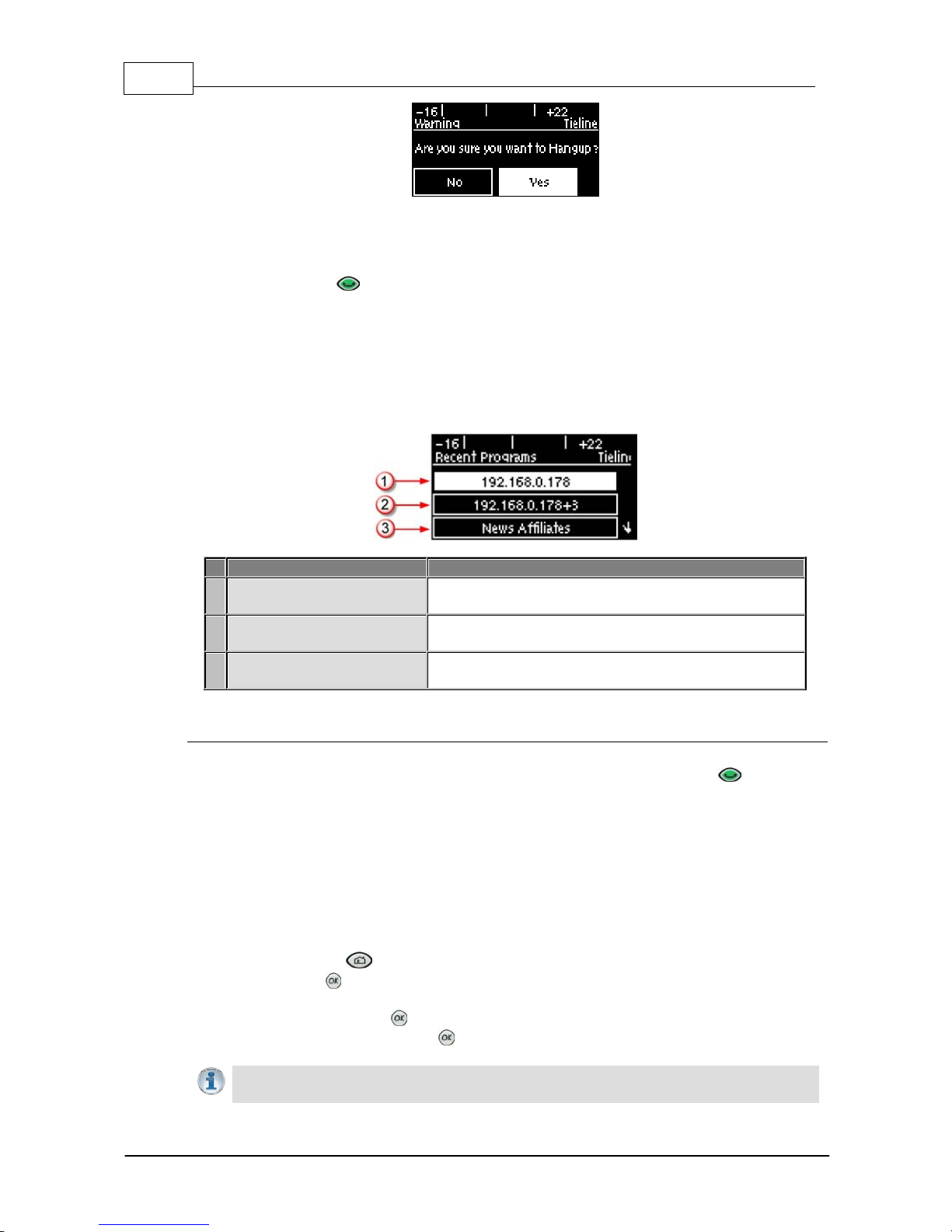
13.4 Disconnecting a Connection
1. Press the red DISCONNECT button on the numeric KEYPAD at any time to hangup a
connection.
2. Use the right navigation button to select Yes and press the DISCONNECT button or the
button to confirm the connection hangup.
Page 36
36 Bridge-IT M anua l
© Tieline Pty. Lt d. 2015
13.5 Redialing a Connection
Press the CONNECT button from any codec menu to redial previous connections (except
menus accessed via the Connect > IP screen).
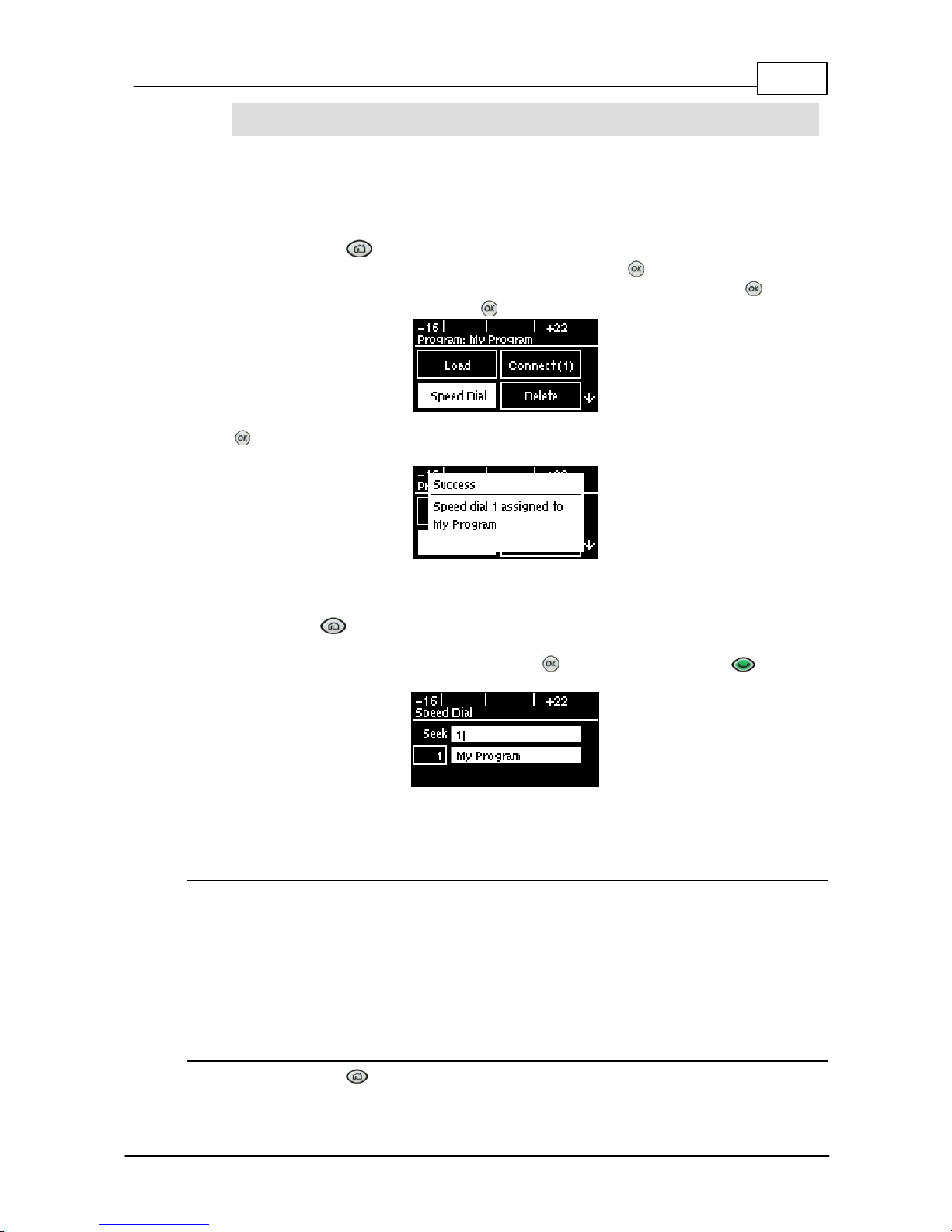
Manually dialed connections are saved as programs - retaining all the dialing and configuration
information programmed into the codec. A program is identified in the Recent Program redial
screen using either a previously entered name, or by an IP address (manually dialed connections).
A multi-unicast connection will display the first IP address dialed and the number of additional
connections dialed.
Screen Display
Description
1
Manual peer-to-peer
connection
Displays the IP address of an IP connection to a single
end-point
2
Manual multi-unicast
connection (via web-GUI)
Displays the IP address of first codec dialed and the
number of additional codec connections
3
Program name (via web-GUI)
Displays the name of a program configured by the
Toolbox web-GUI
Redialing Manually fr om t he Connect I P Screen
From the Home screen select Connect > IP > [Select an IP Session mode] and the codec will
assume you want to dial a new ad hoc manual connection. Press the CONNECT button when
the Connect IP (or Connect SIP) screen is displayed to retrieve previously dialed IP addresses.
Codec settings for any connection dialed from the IP Connect (or Connect SIP) screen will include
the current settings in the Setup menu.
13.6 Configuring A uto R econnect
Auto Re conne ct is dis abled by default. When enabled the dialing codec attempts to reconnect if
data is temporarily lost over an IP connection. To adjust t he sett i ng:
1. Press the HOME button to return to the Home screen, select Connect, then select IP
and press the button.
2. Select the IP Session mode you are using to connect.
3. Select Setup and press .
4. Navigate to A/Recon and press to toggle between Enabled and Disabled.
Importa n t Note: When Auto Reconne ct is enabled, the dialing codec will c ontinue to
attempt a connection with the remote codec until Disconnect is press ed either on the
Page 37
37
© Tieline Pty. Lt d. 2015
Bridge-IT M anua l
dialing codec's keypad, or in the web-GUI. This s et t ing should only be configured on the
dialing codec.
13.7 Speed Dialing Connecti ons
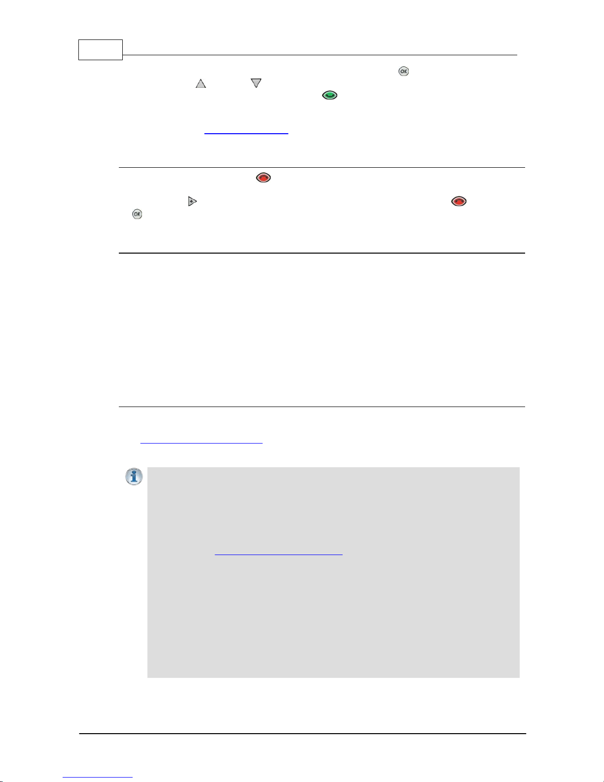
Assigning Speed Dial Numbers
1. Press the HOME button to return to the Home screen.
2. Use the navigation buttons to select Programs and press the button.
3. Navigate to the program you want to assign a speed dial number, then press the button.
4. Navigate to Speed Dial and press the button.
5. Navigate to the speed dial number you want to assign to the selected program and press the
button.
6. A confirmation message will display the number assigned.
Speed Diali ng
1. Press the HOME button to return to the Home screen.
2. Use the numeric KEYPAD to enter the speed dial number.
3. When the Speed Dial screen appears, press the button or the CONNECT button to
connect.
13.8 Dial/Disconnect Multiple Connections
Multi pl e Connections wit hin Programs
Multi-unicast programs allow you to simultaneously transmit a mono or stereo audio stream to up to
6 destination codecs. Multi-unicast programs can only be created using the Toolbox web-GUI. There
are two ways to simultaneously dial multiple IP audio stream connections multi-unicast programs:
1. Load the program into the codec via the front panel and dial.
2. Connect to the codec using the Toolbox web-GUI and use the Master panel to load the
program and connect.
Dialing Mult i pl e Connections via the Front Panel
1. Press the HOME button to return to the Home screen.
Page 38
38 Bridge-IT M anua l
© Tieline Pty. Lt d. 2015
2. Use the navigation buttons to select Programs and press the button.
3. Use the up and down navigation buttons to select the multi-unicast program you want
to connect with, then press the CONNECT button to make a connection.
4. The Wait Connecting screen appears briefly and then the Home screen is displayed.
It is also possible to redial the connection.
Disconnect A l l Connections
1. Press the red DISCONNECT button on the numeric KEYPAD at any time to hangup all
connections.
2. Use the right navigation button to select Yes and press the DISCONNECT button or the
button to confirm the disconnection.
Disconnecti ng Indivi dual Mul ti - unicast Connections
It is only possible to disconnect individual connections via the Master panel in the dialing codec's
Toolbox web-GUI.
13.9 Creating a Multi cast Server Program
Two different types of multicast programs need to be created when multicasting:
· A multicast server program is used by the broadcasting codec to send multicast IP packets
to multicast routers on a network.
· A multicast client program is used by codecs to receive multicast IP audio packets.
Prerequisites:
· Bridge-IT firmware v.1.01.00 r4219 or higher.
· ToolBox web-GUI v.1.2.2.3 or higher.
· A multi-unicast license installed in the dialing codec (Note: the multi-unicast license includes
multicast server capability).
Importa n t Notes:
· You cannot edit a program when it is currently loaded in the codec.
· Ensure all connection related settings like the port, algorithm, bit rate (etc) match on
both multicast server and client programs or they will not be able to join multicast
streaming sessions.
· There is no jitter buffer setting in a multicast server program because it is an encode
only program and never receives audio packets.
· You can lock a loaded custom program in a codec to ensure the currently loaded
program cannot be unloaded by a codec dialing in with a different program type.
· Always dial the multicast server codec connection first before connecting multicast
client codecs.
· Multicast client codecs will display return link quality (LQ) only. The Return reading
represents the audio being downloaded from the network locally. Multicast server
codecs do not display LQ readings.
· Forward Error Correction (FEC) is not available for multicast connections.
· It is not possible for a G3 codec to receive multicast IP audio streams.
· To learn more about programs see the section tit led "A bout Program Dialing".
· See Toolbox web-GUI documentation for more detailed information about "Configuring
Multicast Server Programs" or "Configuring Multicast Client Programs"
Page 39
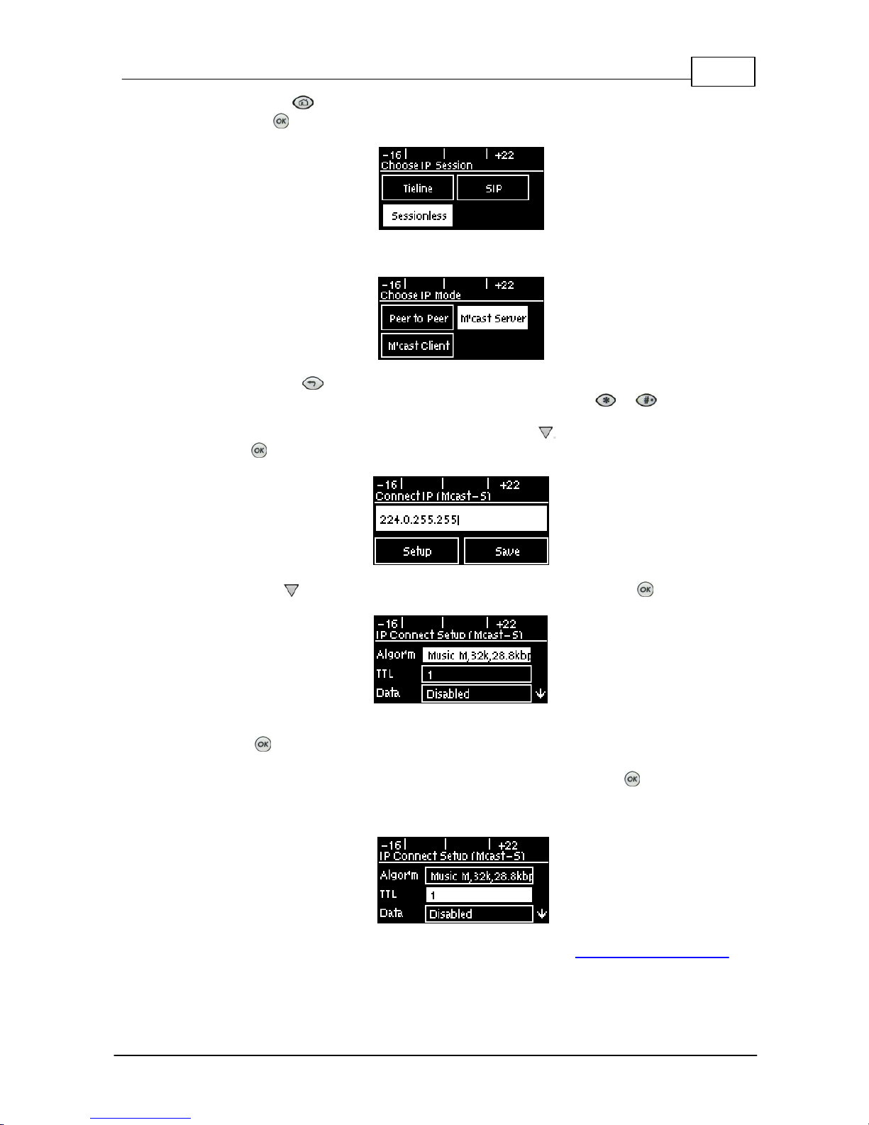
39
© Tieline Pty. Lt d. 2015
Bridge-IT M anua l
1. Press the HOME button to return to the Home screen, select Connect > IP > Sessionless
and press the button.
2. Select M'cast Server to configure a server codec program.
3. Use the RETURN button to delete any numbers already entered, then use the numeric
KEYPAD to enter the multicast IP address you want to dial, using the or buttons to enter
the periods in the IP address. Note: The same multicast address and audio port must be used for
both the server and client programs. Next, press the down navigation button to select Setup
and press .
4. Press the down navigation button to select Algor'm (algorithm) and press .
5. Use the navigation buttons to select an algorithm profile or manually choose algorithm settings,
then press .
6. Navigate to and select TTL and enter the IP Time-to-Live value, then press . Please note: The
TTL value you need to use is dependent upon your network infrastructure. Please consult your
network administrator if you are unsure about how to configure this setting.
7. Select Data to enable or disable data in the audio stream. See RS232 Data Configuration for
more information on data connections.
Page 40
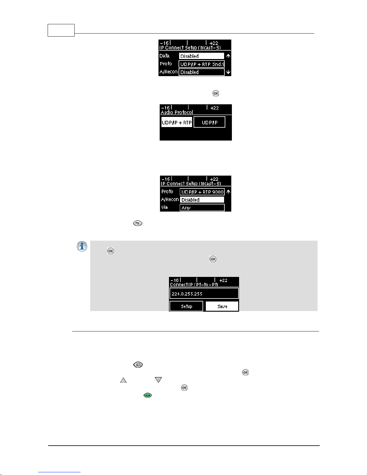
40 Bridge-IT M anua l
© Tieline Pty. Lt d. 2015
8. Select Proto (protocol) to select the audio protocol and adjust the Remote Audio Port. Select
UDP/IP +RTP for RFC-compliant IP streaming. Press to save settings.
9. If required, enable A/Recon (auto reconnect) and use Via to specify which IP streaming interface
is used to dial this connection, e.g. Primary (Ethernet port) or VLAN (if configured). Note: By
default Any will select Primary.
10.Press the RETURN button when configuration is complete to navigate backwards to the
Connect IP screen that the multicast IP address was entered into.
Importa n t Note: At this point you can navigate to Save on the Connect IP screen and
press to s ave the setti ngs as a c us t om program for recall and dialing. Use the numeric
KEYPAD to give the pro gram a name and press t o s ave the program. A c onfirmation
message is dis play ed after the program is s aved.
Connecting a Mult i cast Program
1. After you have created multicast server and client programs on your codecs you can dial
multicast connections. First select the multicast server program you want to use on the server
codec:
a. Press the HOME button to return to the Home screen.
b. Use the navigation buttons to select Programs and press the button.
c. Use the up and down navigation buttons to select the multicast server program you
want to connect with, then press the button to load the program.
d. Press the CONNECT button to make a connection.
2. Select and load the multicast client program on each of the multicast client codecs and dial the
multicast IP address to begin receiving multicast audio packets.
Page 41
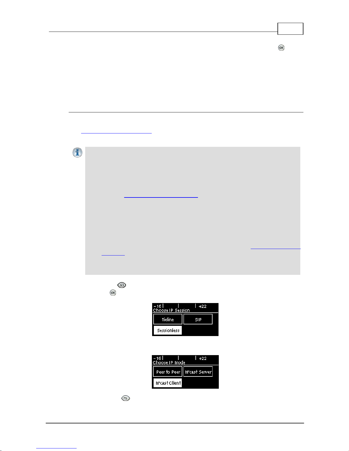
41
© Tieline Pty. Lt d. 2015
Bridge-IT M anua l
Navigate to Cxns on the Home screen to view a codec's connection Status, then press to view
connection statistics for IP packets being sent over the connection.
13.10 Creating a Multicast Client Program
Use the procedure which follows to configure a multicast client program and allow the codec to
receive multicast IP audio packets.
Prerequisites:
· Bridge-IT firmware v.1.01.00 r4219 or higher.
· ToolBox web-GUI v.1.2.2.3 or higher.
· A multi-unicast license installed in the dialing codec (Note: the Multi-Unicast license includes
multicast server capability).
Importa n t Notes:
· You cannot edit a program when it is currently loaded in the codec.
· Ensure all connection related settings like the port, algorithm, bit rate (etc) match on
both multicast server and client programs or they will not be able to join multicast
streaming sessions.
· The default UDP audio port is 9000 for a multicast client program configured via the
codec front panel.
· You can lock a loaded custom program in a codec to ensure the currently loaded
program cannot be unloaded by a codec dialing in with a different program type.
· Always dial the multicast server codec connection first before connecting multicast
client codecs.
· Multicast client codecs will display return link quality (LQ) only. The Return reading
represents the audio being downloaded from the network locally.
· Forward Error Correction (FEC) is not available for multicast connections.
· It is not possible to connect to a G3 codec and receive multicast IP audio streams.
· To copy multicast client programs onto multiple codecs see Backup and Restore
Functions.
· To learn more about programs see the section tit led "A bout Program Dialing".
· See Toolbox web-GUI documentation for more detailed information about "Configuring
Multicast Client Programs"
1. Press the HOME button to return to the Home screen, select Connect > IP > Sessionless
and press the button.
2. Select M'cast Client to configure a client codec program.
3. Use the RETURN button to delete any numbers already entered, then use the numeric
Page 42
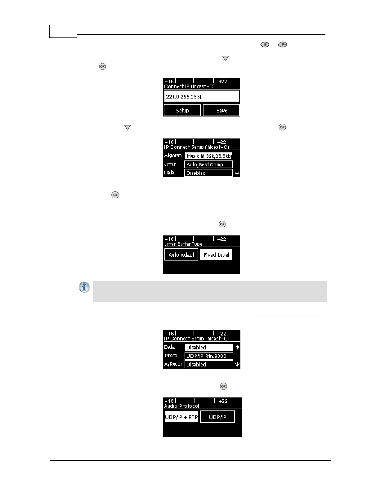
42 Bridge-IT M anua l
© Tieline Pty. Lt d. 2015
KEYPAD to enter the multicast IP address you want to dial, using the or buttons to enter
the periods in the IP address. The same multicast address and audio port must be used for both
the server and client programs. Next, press the down navigation button to select Setup and
press .
4. Press the down navigation button to select Algor'm (algorithm) and press .
5. Use the navigation buttons to select an algorithm profile or manually choose algorithm settings,
then press .
6. Click to configure your preferred Jitter Buffer setting. Select Auto Adapt and your preferred
automatic jitter setting, or Fixed Level. For a fixed buffer setting enter the Jitter Buffer Depth,
which has a maximum setting of 5000ms, then press .
Importa n t Notes: Automatic or fixed jitter buffer settings c an be adjusted on indivi dual
client c odecs as required. There is no jitt er buffer setting on the server codec because it
never receives audio packets .
7. Select Data to enable or disable data in the audio stream. See RS232 Data Configuration for
more information on data connections.
8. Select Proto (protocol) to select the audio protocol and adjust the Local Audio Port. Select
UDP/IP +RTP for RFC compliant IP streaming. Press to save settings.
Page 43
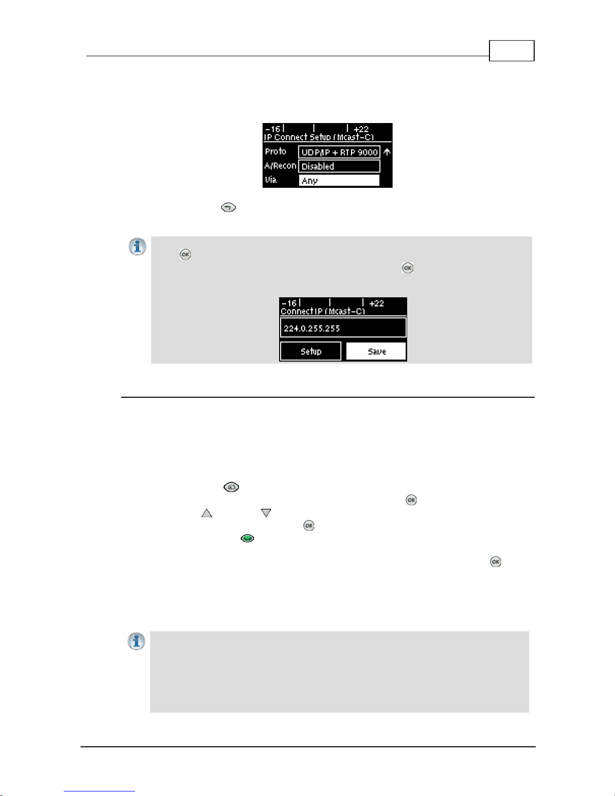
43
© Tieline Pty. Lt d. 2015
Bridge-IT M anua l
7. If required, enable A/Recon (auto reconnect) and navigate to Via to specify which IP streaming
interface is used to dial this connection, e.g. Primary (Ethernet port) or VLAN (if configured).
Note: By default Any will select Primary.
8. Press the RETURN button when configuration is complete to navigate backwards to the
Connect IP screen that the multicast IP address was entered into.
Importa n t Note: At this point you can navigate to Save on the Connect IP screen and
press to s ave the setti ngs as a c us t om program for subsequent recall and dialing. Use
the numeric KEYPAD to give the prog ram a name and press to save the program. A
confirmation message is displayed after the program is s aved.
Connecting a Mult i cast Cli ent Program
1. After you have created multicast server and client programs on your codecs you can dial
multicast connections. First select the multicast server program you want to use on the server
codec and dial to connect.
2. Select and load the multicast client program on each of the multicast client codecs and dial the
multicast IP address to begin receiving multicast audio packets.
a. Press the HOME button to return to the Home screen.
b. Use the navigation buttons to select Programs and press the button.
c. Use the up and down navigation buttons to select the multicast client program you
want to connect with, then press the button to load the program.
d. Press the CONNECT button to make a connection.
Navigate to Cxns on the Home screen to view a codec's connection Status, then press to view
connection statistics for IP packets being received over the connection.
13.11 Dialing SIP Peer-to-Peer
Importa n t Notes:
· The codec is fully EBU N/ACIP Tech 3326 compliant when connecting using SIP
(Session Initiation Protocol) to other brands of IP codecs.
· Both codecs conn ecting over SIP need to be configured
· SIP dialing is only supported over peer-to-peer connect ions, not mult i -unicast
connections.
· Tieline G3 codecs do not support AAC and will default to MP E G Layer 2 if a Bridge-IT
Page 44
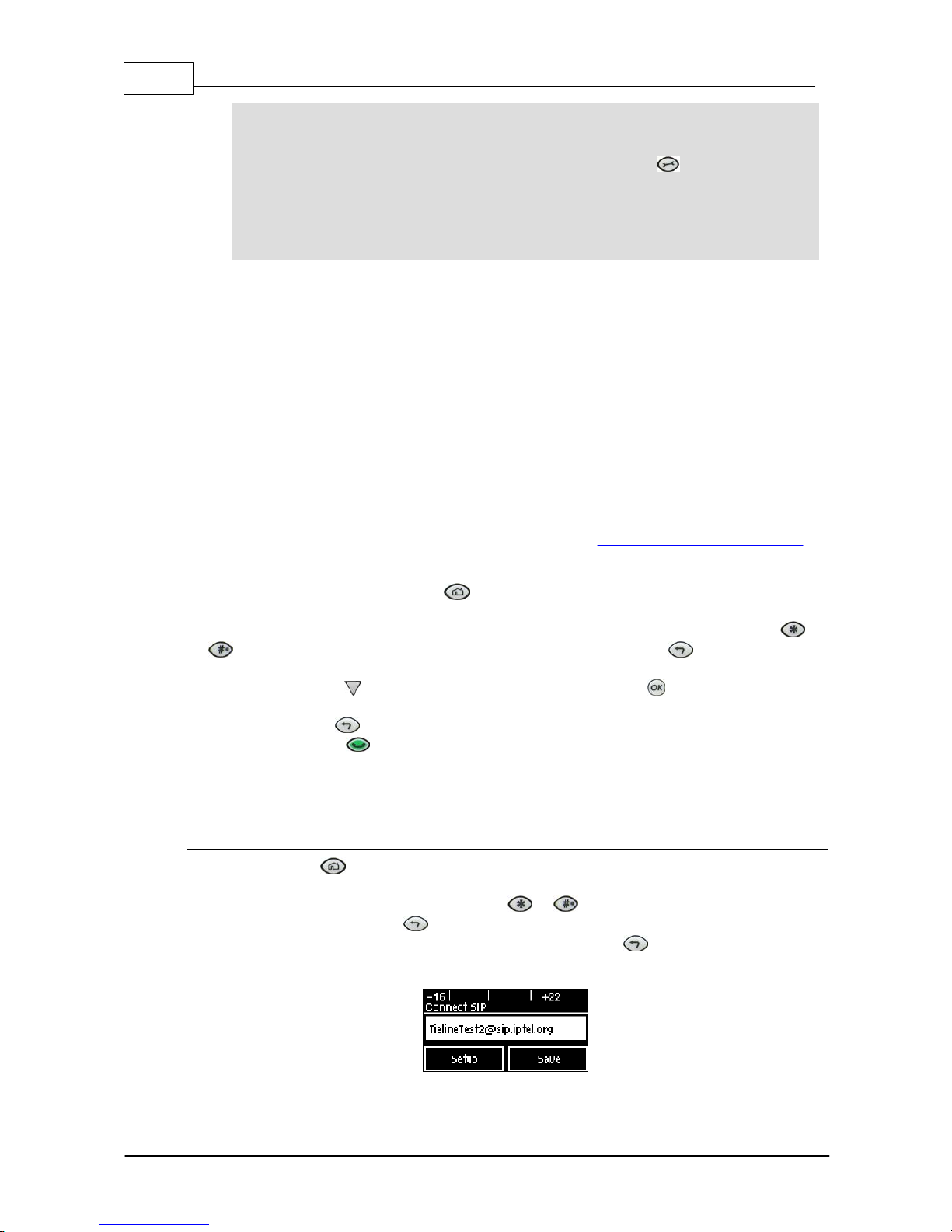
44 Bridge-IT M anua l
© Tieline Pty. Lt d. 2015
codec configured for AAC attempts t o c onnect.
· Some Telcos and ISPs may bloc k S IP traffic over UDP port 5060.
· When connecting to a Tieline G3 codec using SIP you need to manually selec t t he G3
audio reference level in the codec. To do this select SETTINGS > Audio > Re f
Level > Ti eli ne G3. In addition, select t he following on the G3 codec prior to dialing:
Select either a mono or stereo profile
Select [Menu] > [Configuration] > [IP1 Setup] > [Session Type] > [SIP]
Select [Menu] > [Configura tion] > [IP 1 S etup] > [Algorithm] > [G711/G722 or
MP2]
Dialing Peer-to-Peer SIP IP Connections
SIP can be used to make direct peer-to-peer calls to different brands of IP codecs with public IP
addresses, or between two codecs over a LAN which do not pass through firewalls. Peer-to-peer SIP
calls are usually used to connect to other brands of codecs and perform call and session
management tasks. Peer-to-peer SIP calls between two codecs are detected automatically and
require no special configuration.
To make a peer-to -peer call between codecs we recommend both codecs use public IP addresses:
· Find out the IP address of the remote codec being dialed.
· Program each codec with a compatible algorithm and sample rate etc.
· Dial using SIP within the Connect menu.
· If the remote codec has a private IP address then it should be configured for port forwarding
and should dial the public IP address at the studio (see Configuring TCP/UDP Protocols for
more details on port forwarding).
1. To dial peer-to-peer press the HOME button to return to the Home screen, select Connect >
IP > SIP.
2. Use the numeric KEYPAD to enter the IP address of the codec you want to dial, using t he or
buttons to enter the periods in the IP address and use the RETURN button to delete
number s already enter ed.
3. Then press the down nav ig ation button to select Setup and press t o adjust t he algorithm,
jitt er buffer and encode/decode direction if required.
4. Press the RETURN button to navigate backwards to the Connect SIP screen.
5. Press the CONNECT button to make a connection.
13.12 Dialing SIP Addresses
Dialing a SIP Address via the Codec Front Panel
1. Press the HOME button to return to the Home screen, select Connect > IP > SIP.
2. Use the KEYPAD to enter any combination of alphabetic and numeric characters in the SIP
address of the codec you want to dial. Use the or buttons to enter the periods in the SIP
address and use the RETURN button to delete any numbers already entered. Alternatively, if
you have dialed the SIP address previously, press the RETURN button to view the Recent
Call screen and select the SIP address you want.
Page 45
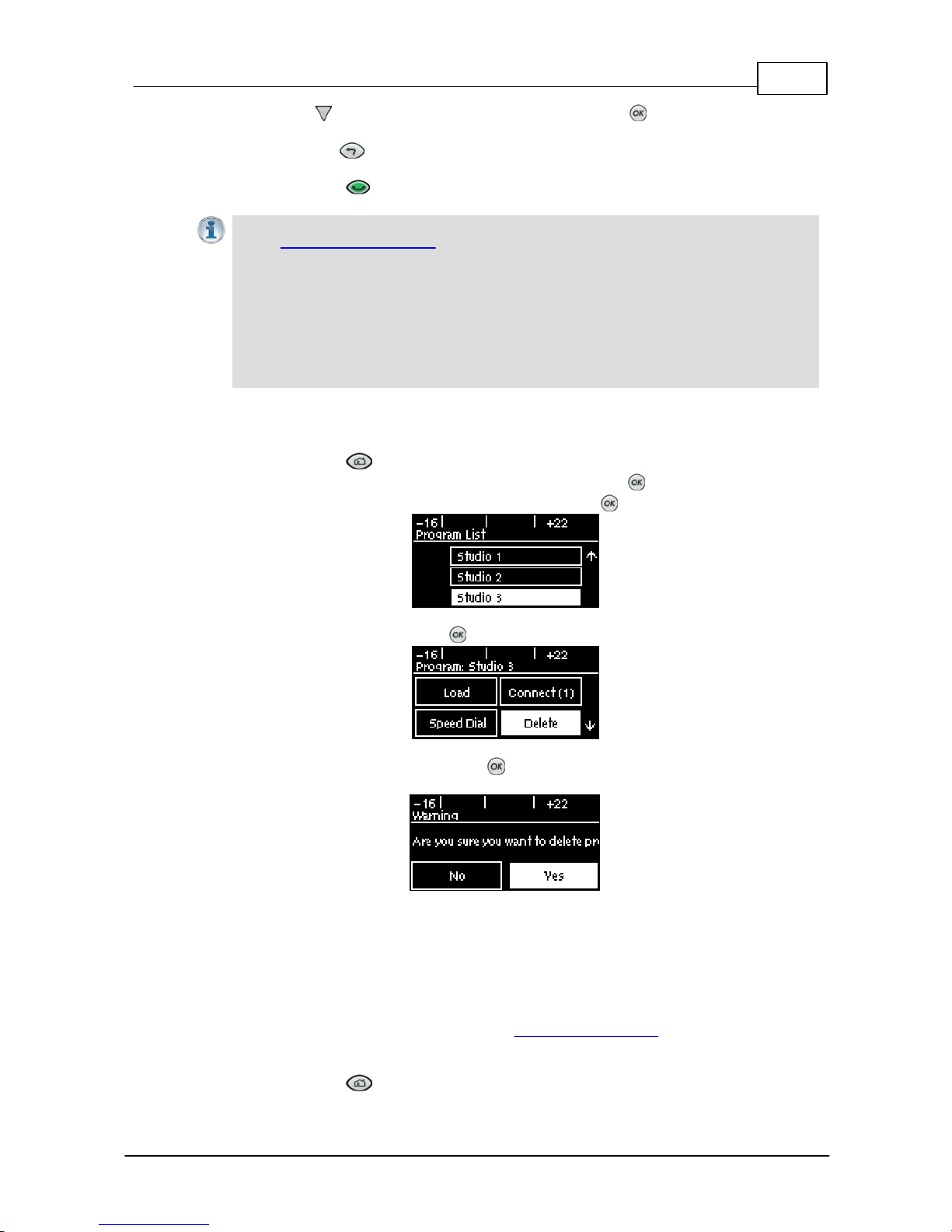
45
© Tieline Pty. Lt d. 2015
Bridge-IT M anua l
3. Press the down navigation button to select Setup and press , then adjust the algorithm,
jitter buffer, encode/decode direction, port and auto reconnect settings if required.
4. Press the RETURN button to navigate backwards to the Connect SIP screen and select
Save to name and save the program.
5. Press the CONNECT button to make a connection.
Importa n t Notes:
· See Configuring SIP Sett ings for instructions on entering SIP acc ount details into t he
codec using the Toolbox web-GUI. If your codec is registered with same SIP registrar as
the destination codec then you only need to enter the SIP user name to dial
successfully.
· Each codec s hould be registered to a different SIP server account to avoid connection
conflicts.
· If you don't s ave the program during configuration, a temporary program is c reated after
you dial the SIP connection for the first time using the codec KEYPAD. The temporary
program will appear in the recent c alls list if you want to redial the program.
13.13 Deleting Programs
1. Press the HOME button to return to the Home screen.
2. Use the navigation buttons to select Programs and press the button.
3. Navigate to the program you want to delete and press the button.
4. Navigate to Delete and press the button.
5. Confirm program deletion and press the button.
13.14 Selecting Algorithm Profiles
The codec has a number of preconfigured mono and stereo dialing profiles available. These can be
used to configure the codec quickly with t he most popular settings that provide high quality
connections usi ng each available algorithm.
If you are unsure about which algorithm to use, see S elect ing an Algorithm for more details on each
algorithm available in the codec.
1. Press the HOME button to return to the Home screen.
Page 46
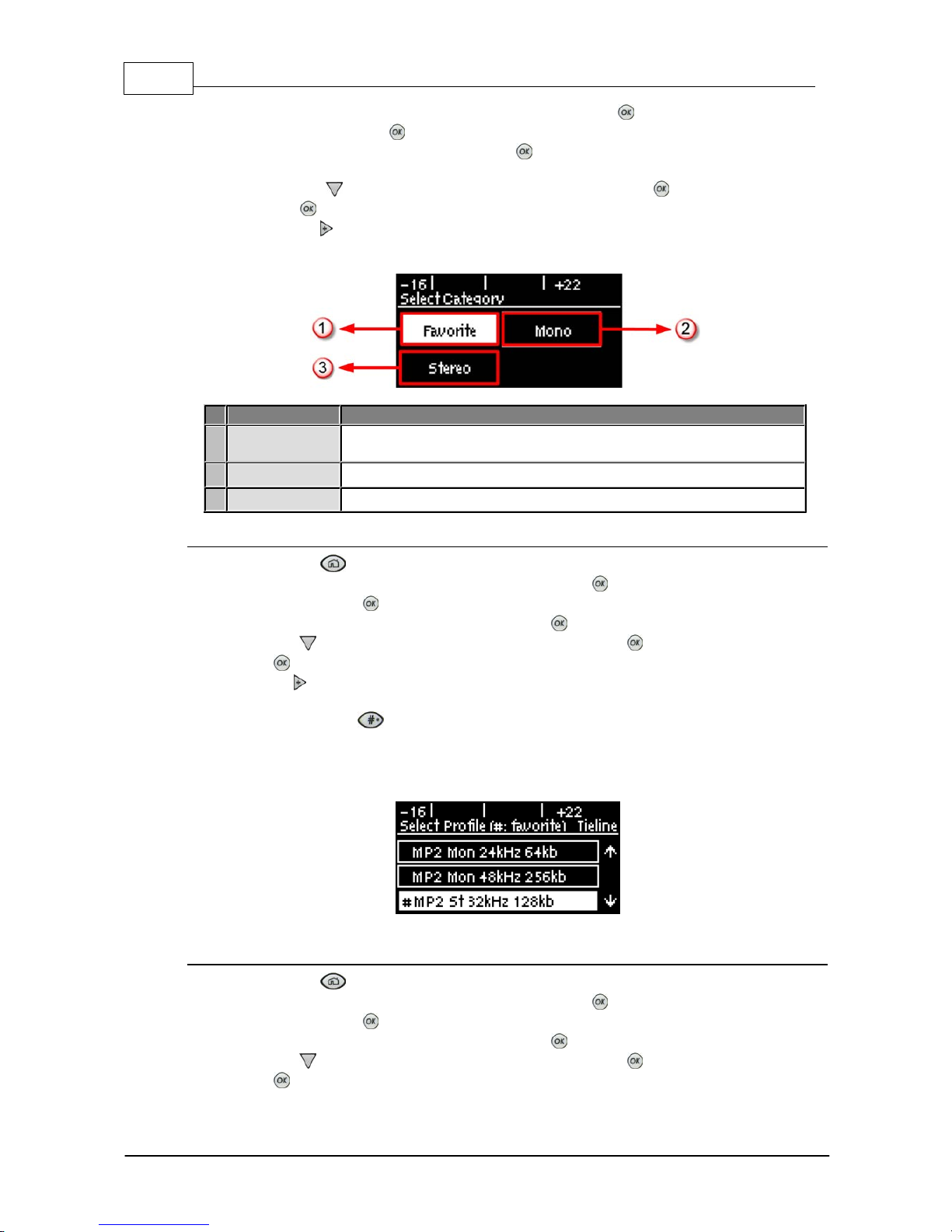
46 Bridge-IT M anua l
© Tieline Pty. Lt d. 2015
2. Use the navigation buttons to select Connect and press the button.
3. Select IP and press the button.
4. Select Tieline session mode and press the button. Note: algorithm profiles are only
available for Tieline sess i on connections.
5. Use the down navigation button to select Setup and press the button.
6. Press the button to select Algor'm.
7. Use the right navigation button to select Profile.
8. Select the profile you want from the Favorite, Mono or Stereo menus.
Features
Codec Home S cre en Elem ents
1
Favorite
Displays a list of favorite profiles that have been selected manually
within the codec by users
2
Mono
Displays preconfigured mono profiles within the codec
3
Stereo
Displays preconfigured stereo profiles within the codec
Adding a Profile i nto t he Favorite Menu
1. Press the HOME button to return to the Home screen.
2. Use the navigation buttons to select Connect and press the button.
3. Select IP and press the button.
4. Select your pref er red IP Ses sion mode and press the button.
5. Use the down navi gation button to select Setup and press the button.
6. Press the button to select Algor'm.
7. Use the right navigation button to select Profile.
8. Select the profile you want from the All, Mono or Stereo menus.
9. Press the hatch button to add the profile into the Favorite menu.
Profiles that have been added into the Favorite menu are identified by the hatch (pound) symbol
next to their name after they have been selected.
Deleting a Profil e fr om the Favorite M enu
1. Press the HOME button to return to the Home screen.
2. Use the navigation buttons to select Connect and press the button.
3. Select IP and press the button.
4. Select your pref er red IP Ses sion mode and press the button.
5. Use the down navigation button to select Setup and press the button.
6. Press the button to select Algor'm.
Page 47

47
© Tieline Pty. Lt d. 2015
Bridge-IT M anua l
7. Use the right navigation button to select Profile.
8. Select the profile you want to delete from the Favorite menus.
9. Press the hatch button to delete the selected profile from the favorite menu.
Avail able Profi l es
The following profiles are pre-configured in all Bridge-IT codecs. Note: AAC and aptX Enhanced
algorithm profiles are not available unless valid licenses have been installed in the codec.
Profiles
Algorithm
Mono/Stereo
Sa m pl e Rate (kHz)
Bit-rate (Kbps)
1
AAC
Mono4864
2
AAC
Stereo
48
128
3
AAC
Stereo
48
256
4
HE-AAC
Mono3216
5
HE-AAC
Stereo3232
6
HE-AAC
Stereo3248
7
AAC-LD
Mono3248
8
AAC-LD
Stereo3264
9
AAC-ELD
Mono3224
10
AAC-ELDv2
Stereo3248
11
Enhanced apt-X
Mono
32 (16 bit)
128
12
Enhanced apt-X
Mono
48 (24 bit)
288
13
Enhanced apt-X
Stereo
32 (16 bit)
256
14
Enhanced apt-X
Stereo
48 (24 bit)
576
15
G.711
Mono864
16
G.722
Mono1664
17
MPEG 1 Layer 2
J-Stereo
32
128
18
MPEG 1 Layer 2
J-Stereo
48
192
19
MPEG 1 Layer 2
Mono2464
20
MPEG 1 Layer 2
Mono48256
21
MPEG 1 Layer 2
Stereo
32
128
22
MPEG 1 Layer 2
Stereo
48
256
23
Music
Mono
32
28.8
24
Music
Mono3248
25
Music
Stereo3264
26
Music
Stereo3296
27
MusicPLUS
Mono4848
28
MusicPLUS
Mono4896
29
MusicPLUS
Stereo4896
30
MusicPLUS
Stereo
48
128
31
MusicPLUS
Stereo
48
192
32
PCM Mono
Mono
48 (16bit)
768
33
PCM Stereo
Stereo
48 (16bit)
1,540
Page 48
48 Bridge-IT M anua l
© Tieline Pty. Lt d. 2015
13.15
SDHC Card Backup
SDHC File Backup
The codec features an SD/SDHC card slot for automatic backup to MP2 or MP3 recordings if an IP
connection is interrupted. Backup connections are configured using the web-GUI and this is outlined
in Configuring Mono or Stereo Peer-to-Peer Programs. USB file backup is automatic and occurs:
1. If encoded audio streaming from a remote codec is lost for a time period predetermined within
the web-GUI (default 30 seconds). Note: Loss of audio is measured by whether data packets
can be received or decoded. If audio is muted at the remote codec and it continues to send
audio packets containing 'silence', the receiving codec will not activate USB file backup.
2. Immediately if a connection to another codec is lost.
Backup will occur according to the silence threshold parameters configured for audio file backup.
After SD/SDHC file backup is activated the audio file plays continuously in loop mode until a backup
connection is dialed and connects, or the primary connection is restored. The codec Home screen
indicates failover to the backup SD/SDHC card has occurred by displaying (F) in the Cxns display.
Playback continues during reconnection attempts and ceases when a connection is restored.
Importa n t Notes:
· File playback will occur automatically if the silence t hreshold parameters are breached; if
the codec is not c onnected for any reason file playback will c ommence. To stop file
playback open the Master panel in the web-GUI, click to select t he file playback
connection, then click Disconnect.
· The USB drive can be inserted or removed at any time as l ong as the codec is not
alread y playing audio in fa ilover mode. A void removing the card while audio is playing or it
will result in poor audio quality . If it is removed acc identally y ou must reboot the codec to
ensure back up audio will c ontinue to operate reliably.
13.16 SDHC Card File Playback
Playing Audio from t he SDHC Card
SDHC card files can be played back using the codec front panel controls.
1. Press the HOME button to return to the Home screen.
2. Select Connect, then select File and press the button.
3. Use the navigation buttons to select a file.
4. Press the button or the CONNECT button to play the selected file.
5. Press the red DISCONNECT button on the numeric KEYPAD to stop file playback.
Importa n t Notes for SDHC Card File P l ayback:
· A FAT32 formatted SDHC Card is required (SD cards may be less reliable and are not
recommended).
· Cre ate MP2 or MP3 files usi ng a 32kHz, 44.1kHz or 48kHz sample rate.
· Ensure recordings used are not variable bit rate files.
· SDHC fi le audio is not sent t o codec encoders and cannot be transmit t ed via an audio
stream to another codec.
· File playback audio is s ent directly to the codec outputs and therefore IGC is not
available. W hen you create your MP2 or MP3 files ensure the audio levels matc h t he
audio reference level of your codec and that peaks average at the correct levels.
· If you create a single file name ensure you add the file extensi on, e.g. " t es t . mp3", or the
file will not play back .
· If you create a direct ory name, all t he files within the direct ory will be played back. We
Page 49
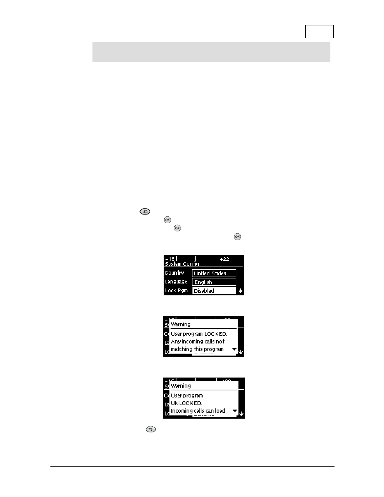
49
© Tieline Pty. Lt d. 2015
Bridge-IT M anua l
recommend you save all audio files as a playli s t and link to t his if you want them to play
out sequentially. P lease note that "M 3U" is t he playlis t file format s upported by t he
codec.
13.17 Lock or Unlock a Program in the Codec
By default Tieline codecs will att empt t o answer a call from another codec if possible. For example, if
a mono program is loaded in the codec and a stereo incoming call is detec t ed, t he codec will adjust
and load a compatible answering program.
It is also poss ible to loc k a loaded custom program in a codec to ensure a program with your
preferred settings is not unloaded when a codec dials in. Incoming calls are generally down or up
sampled to accommodate a locked program where possible. Scenarios in which you may wish to
lock a program in the codec inc lude:
1. Locking a dialing program to ensure the codec only dials and never answers an incoming call.
2. Locking an answering program to ensure an incoming codec call is not allowed to:
· Unload the current codec program, e.g. mono or stereo.
· Change the preferred local site settings like the jitter buffer and FEC configuration etc.
Incoming calls to an answering codec with a locked program can st ill s pecify different connection
parameters s uch as algorithm preferences and bit rates via session data.
1. Press the HOME button to return to the Home screen.
2. Select Settings and press .
3. Navigate to System and press .
4. Navigate to Lock Pgm (lock program) and press to toggle between Enabled and
Disabled.
5. When program lock is Enabled a warning message confirms program status.
6. When program lock is Disabled a warning message confirms incoming calls may load any
supported factory program.
7. Press the RETURN button to exit the warning message.
Page 50
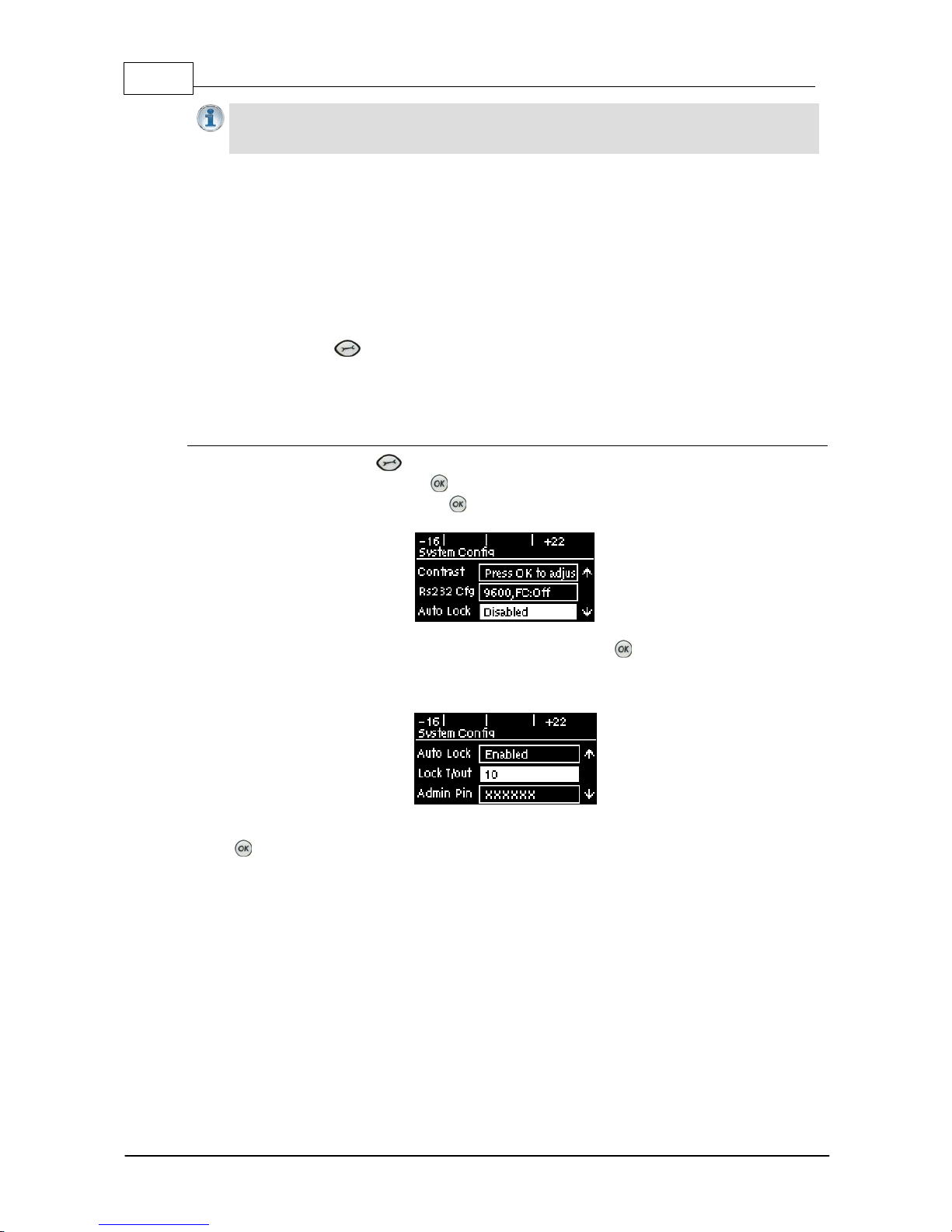
50 Bridge-IT M anua l
© Tieline Pty. Lt d. 2015
Importa n t Note: It is only possible to lock custom programs in a codec. If Lock Program
is enabled and you load a new custom program in the codec, Lock Program remains
enabled and locks t he most recently loaded custom program.
13.18 Locking the Front Panel
The codec features a front panel lock feature for tamper-proof operation. This feature is dis abled by
default.
There are two levels of panel lock and each requires a user to enter a PIN to access different
features:
1. Admin PIN: Required to change codec connection or configuration settings accessed via
the SETTINGS button. (Default PIN is: 456789)
2. User PIN: Required to use the codec front panel buttons and dial/hangup a connection
(Default PIN is: 123456)
Enabling the Front Panel Lock Feature
1. Press the SETTINGS button.
2. Navigate to System and press .
3. Navigate to Auto Lock and press to toggle from Disabled to Enabled.
4. Navigate down to the panel Lock Timeout field and press to enter the desired time-out
period in seconds. Note: The time-out period is the time in seconds before the codec front
panel is relocked after being used.
5. If you want to change the default Admin PIN or User PIN, navigate to each in turn and press
to enter a new PIN.
Page 51

51
© Tieline Pty. Lt d. 2015
Bridge-IT M anua l
14 Connec ting to the T o o lBox Web-GUI
There are three graphical user interface (GUI) options for configuring Tieline G5 codecs:
1. Java Toolbox Web-GUI: codecs can be fully configured including program creation, dial and
hangup, command and control.
2. HTML5 Toolbox Web-GUI: most codec settings can be configured, dial and hangup existing
programs only, plus codec command and control.
3. HTML5 Toolbox Quick Connect Web-GUI: designed for simple peer-to-peer connections and
non-technical users.
About the Java Toolbox Web-GUI
Codecs can be fully configured using the Java ToolBox Web-GUI and this can be launched using an
IP/LAN connection with the codec. Instructions for using the Java web-GUI are contained in the
application itself from the Help panel and additional information is available at http://
www.tieline.com/support/toolbox. The Tieline Java Toolbox Web-GUI application runs on:
· Internet Explorer 6 or greater on Windows® XP, Windows Vista ® and Windows 7 ®.
· Firefox® 3 or greater on Windows® XP, Windows Vista ® and Windows 7 ®, Solaris™ and
Linux®.
Java Toolbox Web-GUI Prerequisi tes
1. To use the Java ToolBox Web-GUI you will need to download the latest version of Java™ by
visiting http://www.java.com. The Web-GUI will prompt you to do this if Java is not installed
and you attempt to launch the Java ToolBox Web-GUI.
2. After updating to the latest version of Java you need to refresh your browser.
About the HTML5 Toolbox W eb-GUI
The HTML5 Toolbox Web-GUI was developed to improve the user experience with G5 codec
command and control. With some major web-browsers moving away from Java compatibility, Tieline
has delivered an HTML5 configuration option which runs seamlessly on modern browsers.
The HTML5 Toolbox Web-GUI will run on computers and tablets, as well as iOS and Android
smartphones, which expands the range of devices engineers can now use for configuration. In
addition, many users have previously experienced connectivity issues due to regular Java updates
designed to mitigate exposure to security vulnerabilities. By using the HTML5 Toolbox these issues
will be avoided.
Most codec settings can be configured using the HTML5 Toolbox Web-GUI, including:
· Dial, monitor and hangup existing programs only (currently program creation wizard is not
available).
· Extensive command and control of codec settings.
About the HTML5 Toolbox Quick Connect
The HTML5 Toolbox Quick Connect Web-GUI has a reduced feature-set and allows non-technical
users to load existing programs and dial via the Quick Connect panel. Users can dial a simple peerto-peer connection over IP or SIP.
Page 52
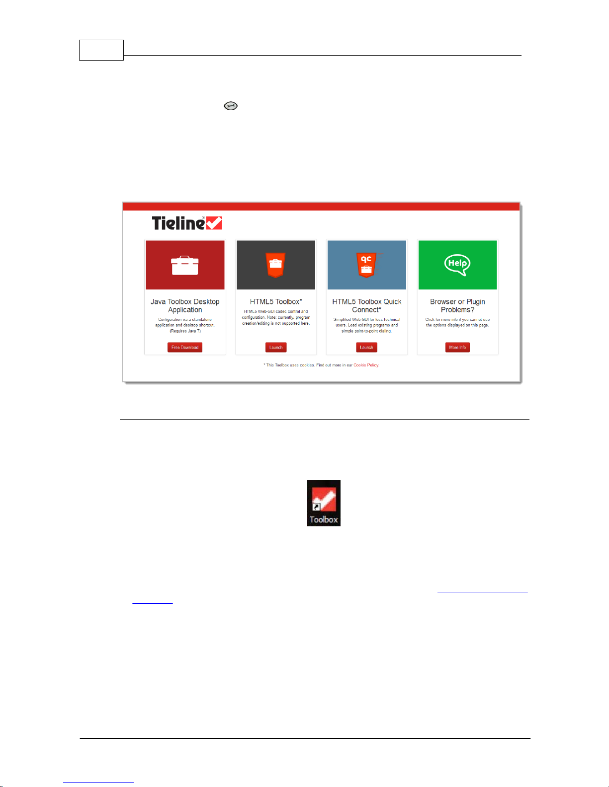
52 Bridge-IT M anua l
© Tieline Pty. Lt d. 2015
14.1
Opening the Java or HTML5 W eb-GUI & Login
1. Attach an Ethernet cable to the ETH1 port on the codec.
2. P ress t he SETTINGS button and select Unit to display t he IP address programmed into your
codec.
3. Ensure your PC is connected to the same LAN.
4. Open your web browser and type the IP address of your codec into the address bar of your
browser, e.g. http://192.168.0.xxx (the last digits are the private address details unique to your
codec over a private LAN).
5. Refresh the browser and the Web-GUI landing page will display the various command and control
options.
Launching the Java Toolbox Web-G UI
1. Click to launch the Java ToolBox Desktop Application (this is recommended in preference to
launching the Java Toolbox Browser Applet). Note: When you launch for the first time the
application will download and launch the desktop Toolbox application that will allow you to
configure your codec. A desktop short-cut will also be created.
Icon
2. When you launch Toolbox an authentication dialog prompts you to enter a password to login. The
first time you log in you can enter the default setting "password" and click the OK button. Tieline
highly recommends you click the hyperlink in the login dialog or visit Changing the Default
Password to change the password. This will provide better network security to maintain reliability
during live broadcasts.
Page 53
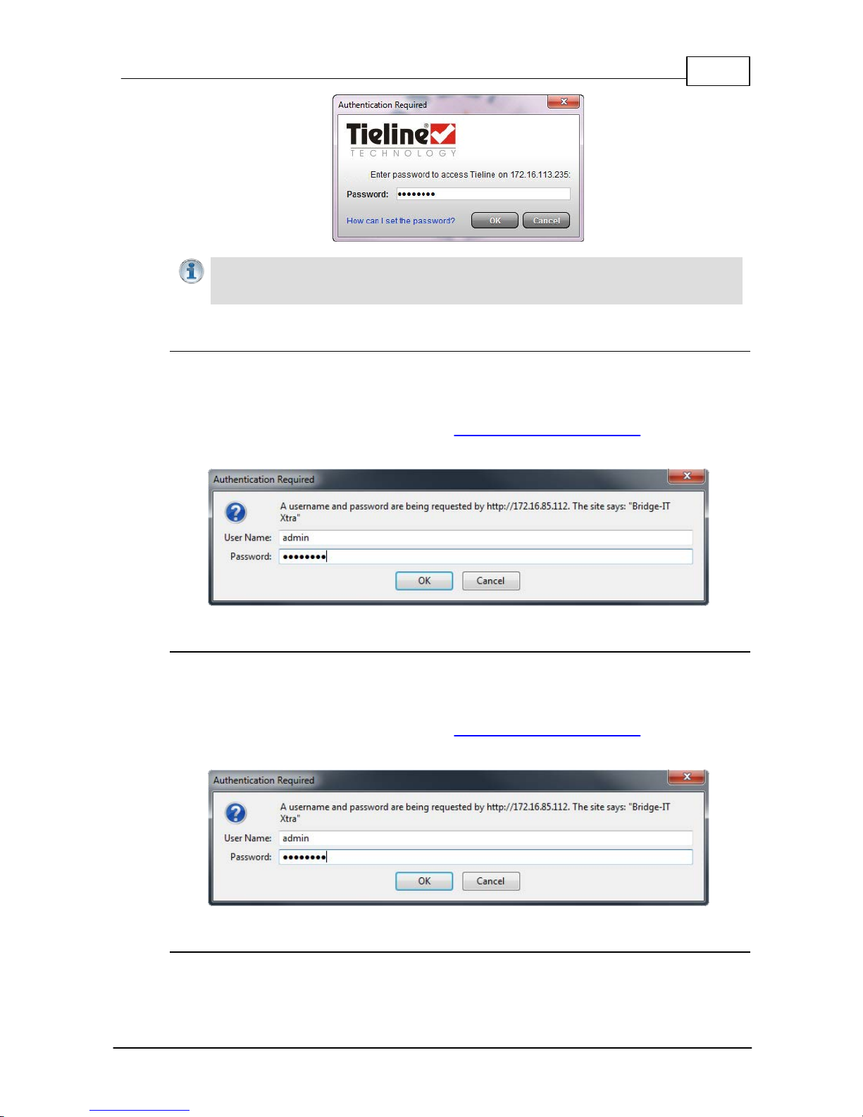
53
© Tieline Pty. Lt d. 2015
Bridge-IT M anua l
Importa n t Note: If you update Java s oftware or clear the Java c ache on your computer you
will need to repeat the pre cedin g steps. If you have t rouble launching the Web-GUI in a
browser, type http://<insert codec IP address>.htm directly in your browser.
Launching the HTML5 Toolbox Web-GUI
1. Click to launch the HTML5 Toolbox Web-GUI.
2. When you launch Toolbox for the first time an authentication dialog prompts you to enter the user
name "admin" and password "password" to login, then click the OK button. Tieline highly
recommends you change the password (see Changing the Default Password). This will provide
better network security to maintain reliability during live broadcasts.
Launching the HTML5 Toolbox Quick Connect
1. Click to launch the HTML5 Toolbox Quick Connect Web-GUI.
2. When you launch Toolbox for the first time an authentication dialog prompts you to enter the user
name "admin" and password "password" to login, then click the OK button. Tieline highly
recommends you change the password (see Changing the Default Password). This will provide
better network security to maintain reliability during live broadcasts.
Using the Web-GUI over the Internet
If your codec is connected over the internet via a public static IP address it is possible to connect
and configure it from any PC which is also connected to the internet.
Page 54

54 Bridge-IT M anua l
© Tieline Pty. Lt d. 2015
LAN Troubleshooting
PC LAN Setti ngs
Check the LAN settings on your PC if it is connected to a LAN and is having trouble opening the
Toolbox Web-GUI in a web-browser.
1. Open Internet Explorer.
2. Click Tools > Internet Options > Connections.
3. Click the LAN settings button.
4. If the PC is using a proxy server over the LAN you may need to select the Bypass
proxy server for local addresses option box.
5. If you still can't connect, click the Advanced button in the LAN Settings dialog and ask
your IT administrator to assist you with entering the IP address of the codec into the
Exceptions pane of the Proxy Settings dialog.
Port Selection
By default port 80 is used by your PC to communicate with the codec and launch the web-GUI.
If port 80 cannot be used across your network for some reason, type the IP address of your
codec into your browser with a full colon and the port number 8080.
E.g. 192.168.0.176:8080
It is also possible to specify a different port for connecting the Toolbox web-GUI to your codec.
1. Press the HOME button on the codec to return to the Home screen.
2. Use the navigation buttons to select Settings and press the button.
3. Use the navigation button to navigate down to WebGUI and press the button.
4. Select Alt. Port and press .
5. Use the KEYPAD to enter a new port number and press the button to save the new
setting.
6. Type the IP address of your codec into your browser with a full colon and then the new
port number.
Importa n t Note: Any new port s pecified must be within the range 2000 to 65535 inclusive.
Page 55
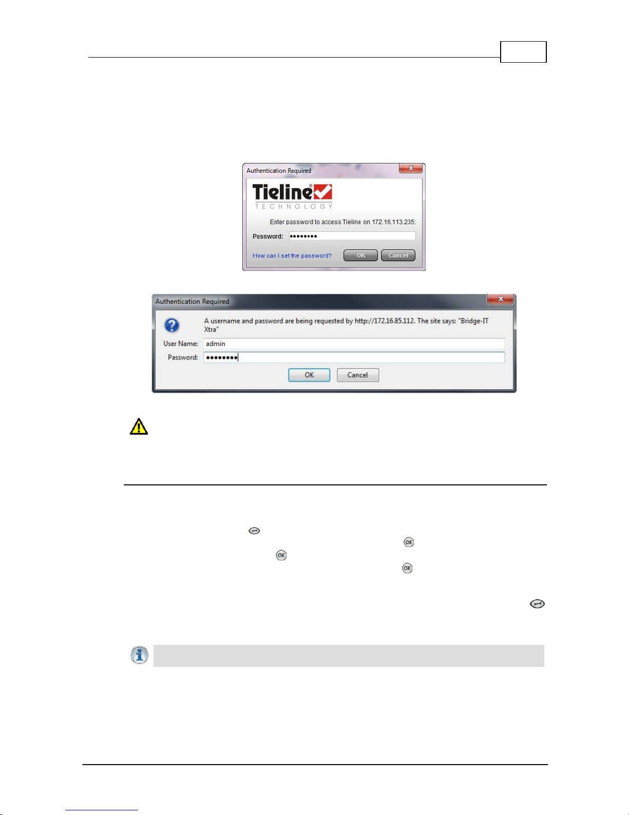
55
© Tieline Pty. Lt d. 2015
Bridge-IT M anua l
14.2
Changing the Default Password
The default password for the Toolbox Web-GUI is password. Enter this in the authentication dialog
to use the Web-GUI initially and then Tieline highly recommends changing the default password to
protect your codec from being tampered with during live broadcasts. Note: In the HTML5 Web-GUI
authentication dialog it is necessary to enter admin as the User Name. This field is not visible in
the Java Web-GUI authentication dialog.
Toolbox Java Web -GUI Login Dialog
Toolbox HTML5 We b-GUI Logi n Dialog on a Me rl i n Code c
Caution: Codecs c onnected to the internet can be accessed by anyone with knowledge of
the codec's public IP address . Set t ing a st rong password protects your equipment from
being tampered with during live broadcasts.
Creating a New Password
The authentication login password can be changed at any time using the codec keypad and LCD
screen. Note that passwords are case sensitive:
1. Press the SETTINGS button.
2. Use the navigation button to select WebGUI and press the button.
3. Select Password and press .
4. Use the KEYPAD to enter a new password and press the button to save the new setting
(Note: there is no character limit for passwords).
If you forget the password for the Toolbox web-GUI then you can always press the SETTINGS
button on the codec and navigate to WebGUI to view the current password and change it if
required.
Importa n t Note: The Username in the codec menu is permanently set to admin and
cannot be changed ; only the Password can be changed.
Page 56
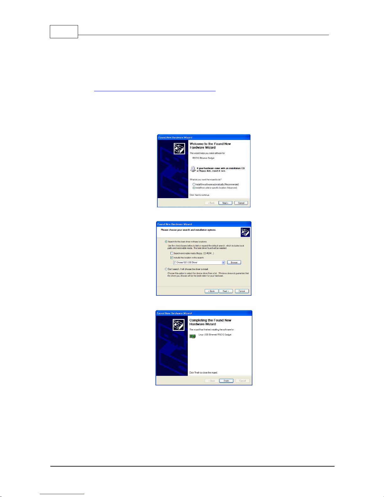
56 Bridge-IT M anua l
© Tieline Pty. Lt d. 2015
14.3
Installing USB Drivers
USB drivers need to be installed on your PC in order to connect successfully to the codec using
the USB port. To install drivers:
1. Download the zipped USB driver ".inf" file from the Bridge-IT firmware download pages at
http://www.tieline.com/Support/Latest-Firmware.
2. Unzip the file and save it to your PC.
3. Connect a USB cable between your PC and the Bridge-IT USB port on the rear panel of the
codec.
4. The PC should detect that a new device has been attached and launch the Found New
Hardware Wizard.
5. Select Install from a list or specific location (Advanced) and click Next.
6. Select the folder in which you have saved the downloaded ".inf" file and click Next.
7. When the drivers have been installed click the Finish button.
Page 57
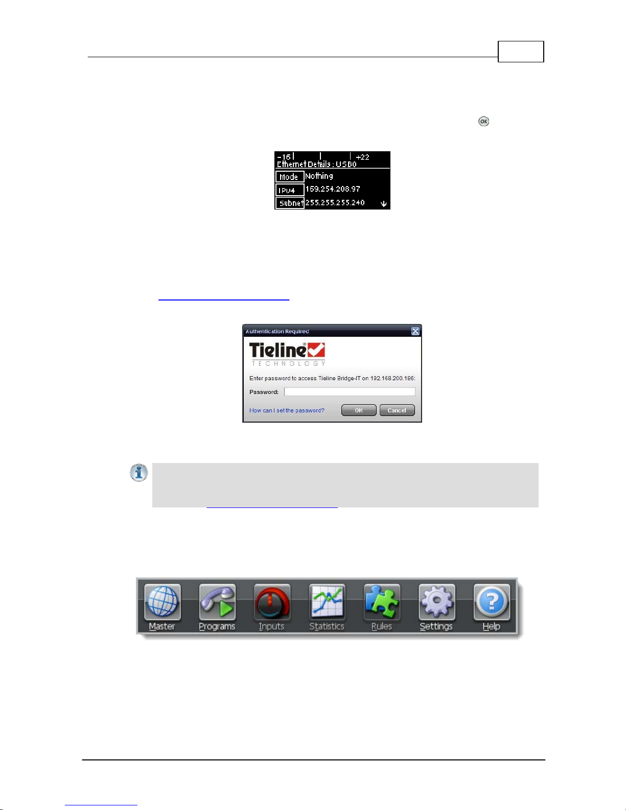
57
© Tieline Pty. Lt d. 2015
Bridge-IT M anua l
14.4
Launching the GU I over U SB
1. Install USB drivers into your PC.
2. Connect a USB cable between your PC and the USB port on the rear panel of the codec.
3. From the codec Home scree n navigate to Se ttings > Unit > USB0 a nd press the button to
display the USB address details c onfigured into your codec.
4. Open your web browser and type the USB address of your codec into the address bar of your
brow ser, i.e. http://169.254.x.y (the last 2 block s of digits are the USB address details unique to
your codec).
5. Refresh the browser and the web-GUI should launch automatically.
6. When you open the ToolBox web-GUI an authentication dialog prompts y ou to enter a pass word
to login. The first time you log in enter the default setting "password" and click the OK button.
(See Changing the Default P as s word for instructions on changing the default password to
increase your network sec urity ).
15 Java T o o lbox Web -GUI Introduction
Importa n t Note: Th e default password for the web- GUI is password. This has to be
entered to initially us e t he Toolbox web-GUI. For additional security Tieline highly
recommends changing the authentication login password using the codec k eypad and
scree n (see Changing the Default P as s word for more info).
The following sections provide an overview of the different programming panels available within the
codec's Toolbox web-GUI. Navigate with the mouse pointer to a symbol at the top of the web-GUI
screen and click to open the panel selected. When a panel is opened in the web-GUI, the text
below the symbol at the top of the screen is highlighted (see Master in the following image).
Web-GUI Symbols for Opening Pane l s
Page 58
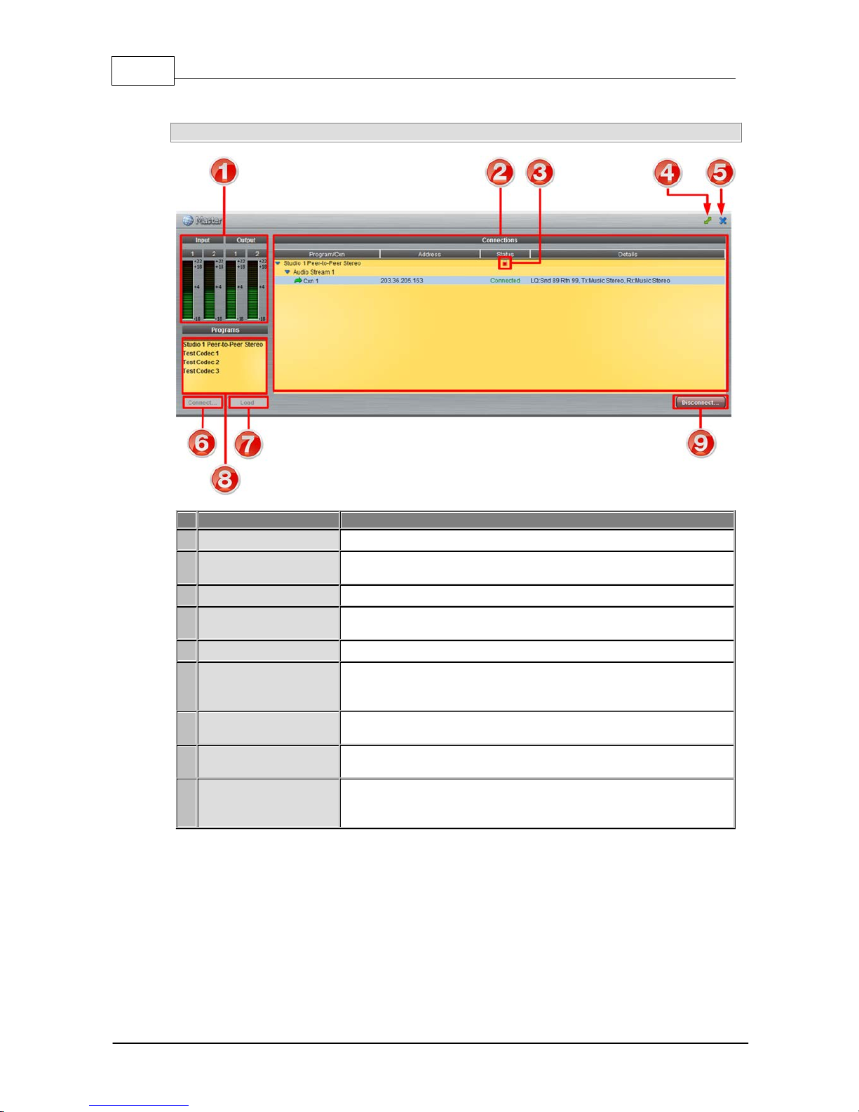
58 Bridge-IT M anua l
© Tieline Pty. Lt d. 2015
Master Panel to Load Programs and Connect Audio Streams
Feature
Description
1
Input/Output PPMs
4 PPM meters to display audio levels for inputs and outputs
2
Connections
Provides a summary of audio stream and connection details audio
streams
3
Locked program
Symbol indicates the currently loaded program is locked
4
Maximize/Minimize
Click to maximize a panel to view it in full-screen mode, or click to
minimize back to the default panel size
5
Close button
Click to close the Master panel
6
Connect button
Click Connect to connect all audio streams configured within the
currently selected program in the Programs list; this button also
loads the program currently selected in the Programs list
7
Load button
Click to Load the codec with the program currently selected in the
Programs list
8
Programs list
Lists all configured programs which have been added into the
codec. Click to select a program before loading or connecting
9
Disconnect button
Click to disconnect the currently selected audio stream or a
specific connection. Note: this button becomes a Connect or
Unload button when all audio streams are disconnected.
Page 59
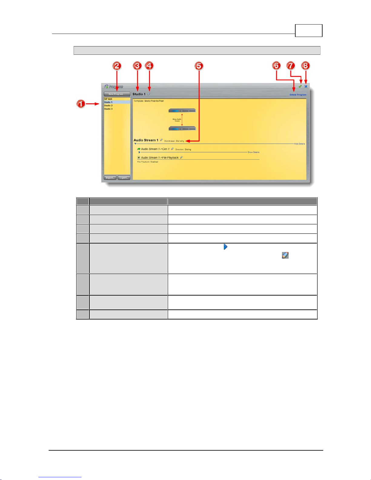
59
© Tieline Pty. Lt d. 2015
Bridge-IT M anua l
Programs Panel for Connection Configuration
Feature
Description
1
Programs List
Displays all programs in the codec
2
New Program button
Click to add a new program.
3
Program Name
The name of the currently selected program in the panel.
4
Edit Name
Click to edit the name of the currently selected program.
5
Audio Stream overview
Click the blue arr ow s to expand audio stream and
connection inf orma tion; click the Edit symbol to adjust
program setti ngs. This panel display s t he program wizard
when creating a new program.
6
Delete Program
Click to delete the currently selected program (Note:
Ensure the program is not loaded or the delete function will
not work).
7
Maximize/Minimize
Click to maximize a panel to view it in full-screen mode, or
click to minimize back to the default panel size
8
Close button
Click to close the Connect panel.
Page 60
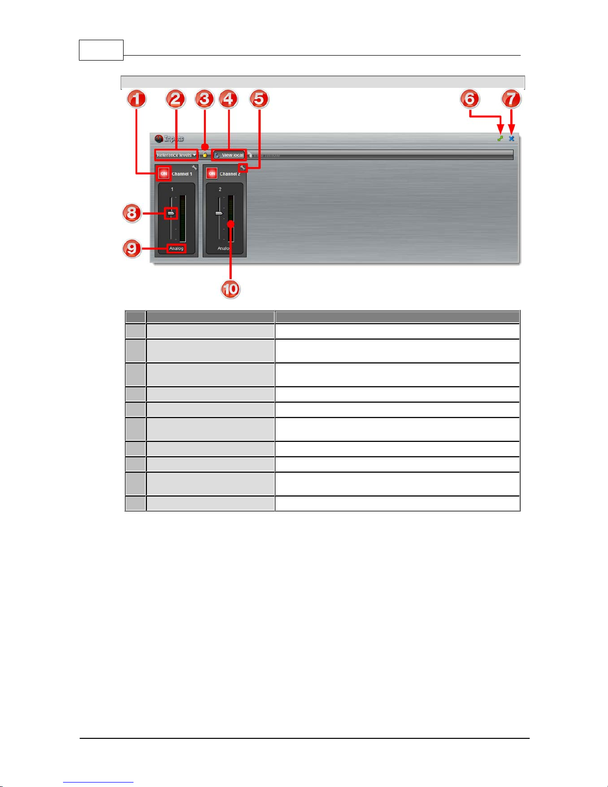
60 Bridge-IT M anua l
© Tieline Pty. Lt d. 2015
Inputs Panel for Adjusting Input Levels
Feature
Description
1
Channel ON/OFF Buttons
Click to turn each channel ON or OFF
2
Reference levels menu
Click the drop-down arrow to select the codec input
reference level (default setting Auto)
3
Lock Button
Click to lock all Input panel settings (greys out when
locked)
4
View local
Click to view local codec inputs (default)
5
Settings button
Click to adjust input Name, Type, IGC and Ganging
6
Maximize/Minimize
Click to maximize a panel to view it in full-screen mode, or
click to minimize back to the default panel size
7
Close button
Click to close the panel
8
Input Sliders/Faders
Input gain control sliders/faders
9
Analog/AES3 Indication
Indicates whether the codec input is configured for analog
or digital audio sources
10
Input PPM meter
Input PPM meter
Page 61
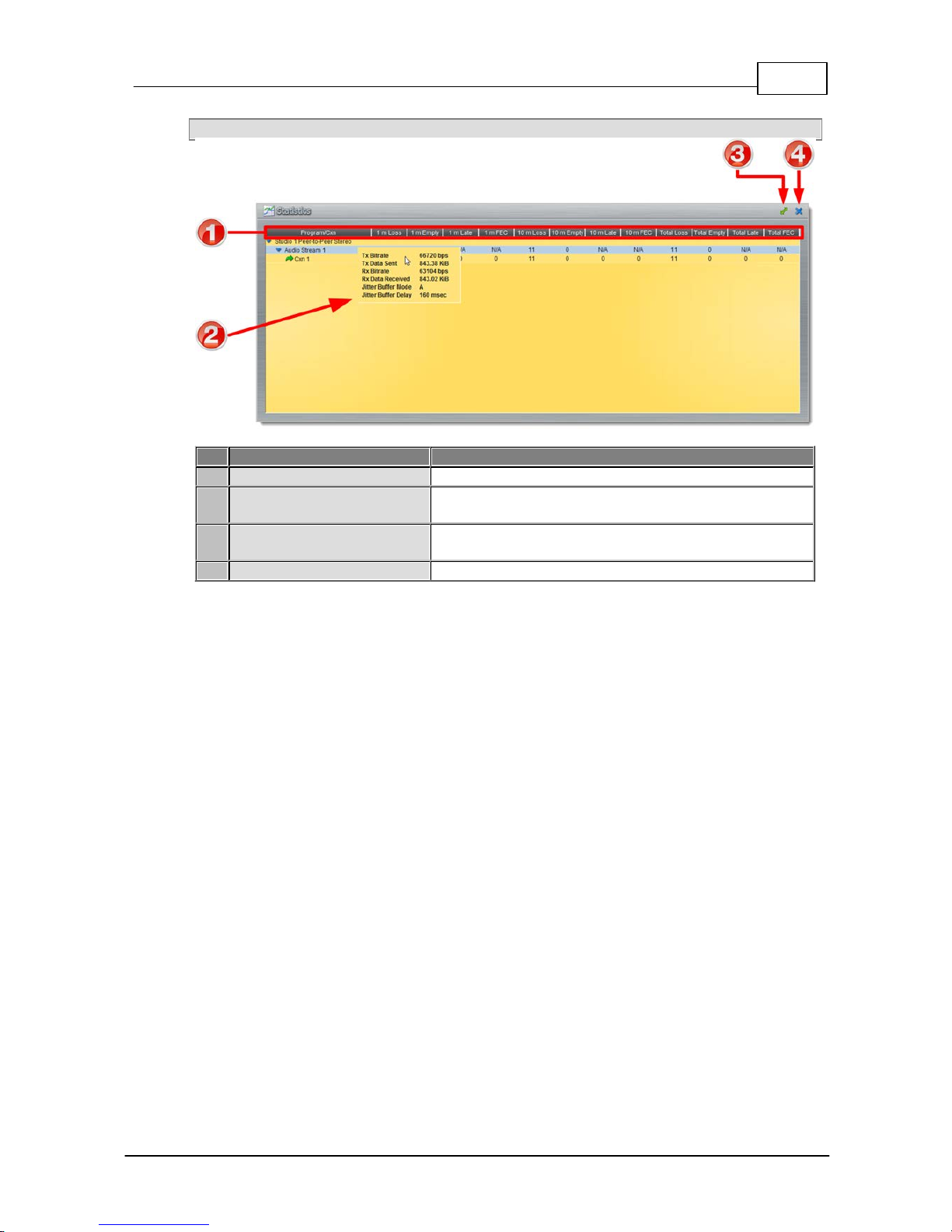
61
© Tieline Pty. Lt d. 2015
Bridge-IT M anua l
Statistics Panel for Monitoring Connection Stability
Feature
Description
1
Headings
Headings for the various packet arrival statistics available
2
Connection Statistics
Right-click to view audio stream bit-rate and jitter buffer
statistics
3
Maximize/Minimize
Click to maximize a panel to view it in full-screen mode, or
click to minimize back to the default panel size
4
Close button
Click to close the panel
Page 62
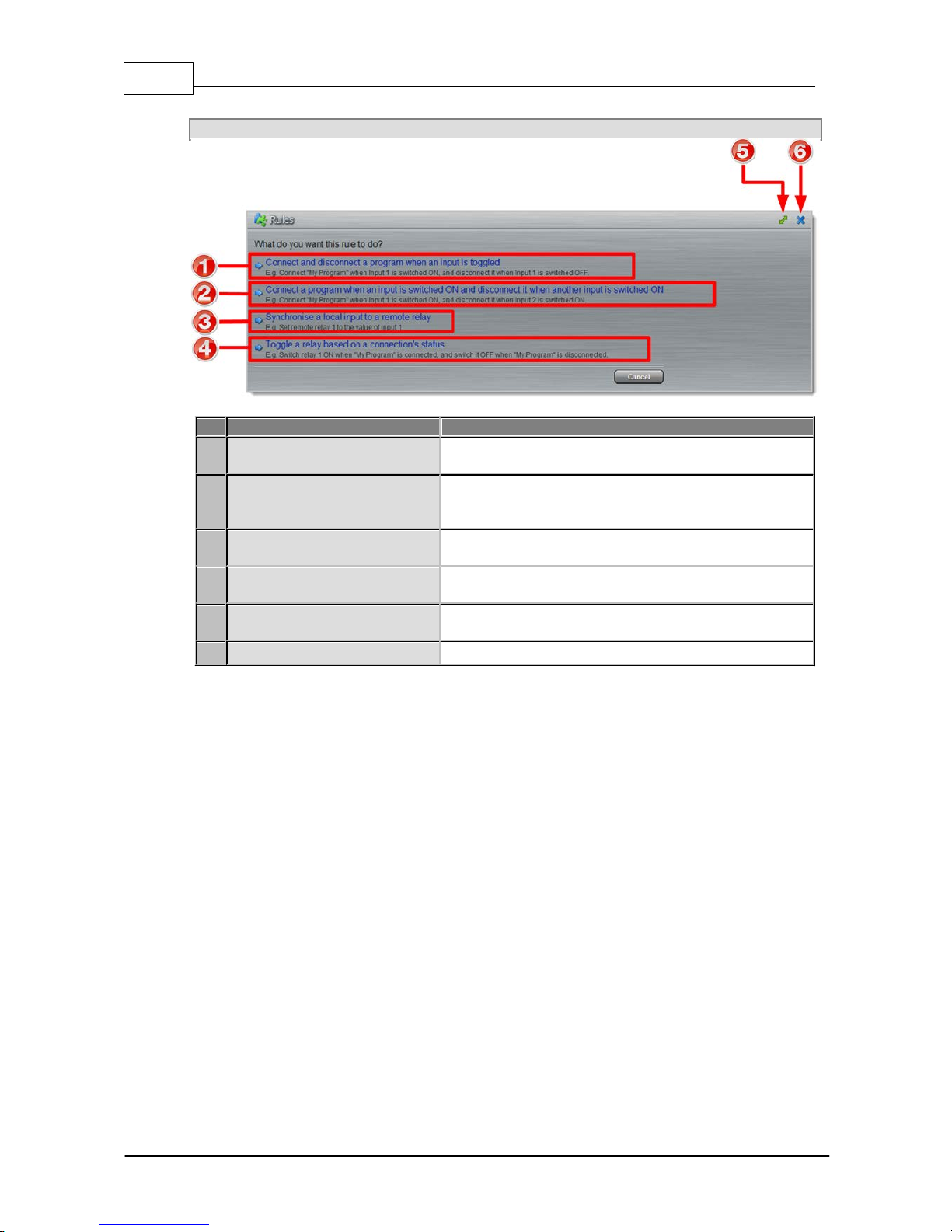
62 Bridge-IT M anua l
© Tieline Pty. Lt d. 2015
Rules Panel for Creating Relay Activation Rules
Rule
Description
1
Connect/Disconnect a program
by toggling a relay input
Click to program Connection and Disconnection by
toggling an input
2
Connect when an input is
switched ON; Disconnect when
another input is switched ON
Click to program Connection and Disconnection after
different relay inputs are switched ON
3
Synchronise a local relay input
with a remote relay output
Click to program a local relay input to Synchronise with
the state of a remote relay output
4
Toggle a relay based on
connection status
Click to program a relay to toggle based on connection
status
5
Maximize/Minimize
Click to maximize a panel to view it in full-screen mode,
or click to minimize back to the default panel size
6
Close button
Click to close the Rules panel
Page 63
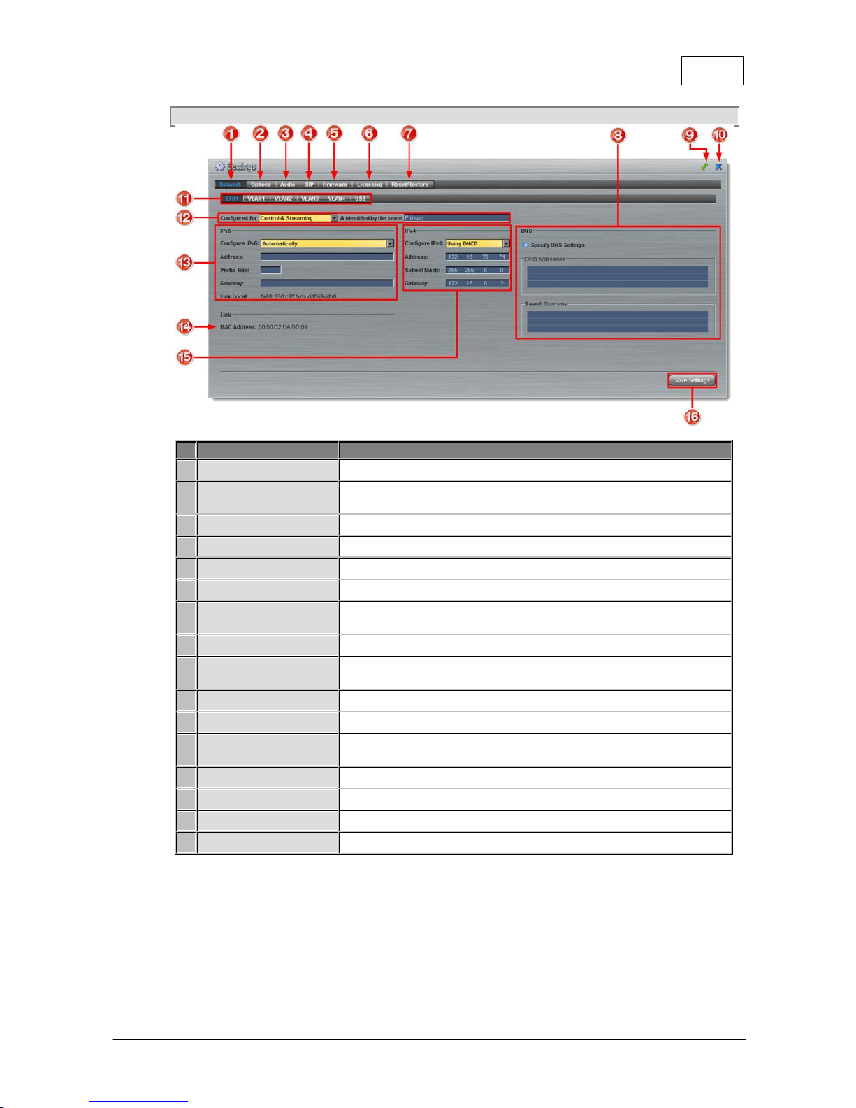
63
© Tieline Pty. Lt d. 2015
Bridge-IT M anua l
Settings Panel
Feature
Description
1
Network tab
Click to edit or view codec network configuration settings
2
Options tab
Click to configure RS232 and QoS data settings, lock a loaded
user Program and Adjust Session Port settings
3
Audio tab
Click to configure the AES Output Clock sample rate
4
SIP tab
Click to edit or view SIP configuration settings
5
Firmware tab
Click to view software versions and perform an upgrade
6
Licensing tab
Click to select a license file and install it into the codec
7
Reset/Restore tab
Click to reset codec default settings and perform backup/restore of
codec programs and settings
8
DNS Pane
Activate to specify DNS addresses and domains to search.
9
Maximize/Minimize
Click to maximize a panel to view it in full-screen mode, or click to
minimize back to the default panel size
10
Close button
Click to close the panel
11
Network Interface
Select a network interface for configuration options
12
Network Interface
Identifier
Control and streaming configuration options for each network
interface, e.g. Ethernet Port or LAN.
13
IPv6 details
IPv6 addressing details and configuration
14
MAC Address
Device MAC address
15
IPv4 details
IPv4 addressing details and configuration
16
Save Settings button
Saves all configuration settings
Page 64
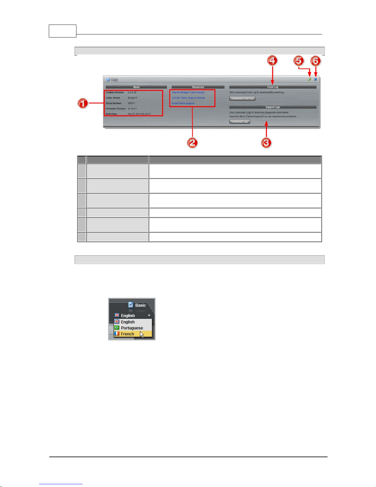
64 Bridge-IT M anua l
© Tieline Pty. Lt d. 2015
Help Panel for Product Support
Feature
Description
1
About
Details about the Toolbox web-GUI and codec firmware version, as
well as the codec type and codec serial number
2
Resources
Links to open the user manual in a new browser, or view support
information
3
Support Logs
Click to download diagnostic information that can be sent to Tieline
support
4
Event Logs
Click to download user-viewable event logs
5
Maximize/Minimize
Click to maximize a panel to view it in full-screen mode, or click to
minimize back to the default panel size
6
Close button
Click to close the Help panel
Language Selection
The Toolbox web-GUI offers l anguage support for several languages.
1. Click on the language drop-down menu arrow in the top right-hand corner of the web-GUI page.
2. Select your language of choice.
3. Click to refresh your web-browser and download the user manual for the language selected.
Page 65

65
© Tieline Pty. Lt d. 2015
Bridge-IT M anua l
16 Java T o o lbox Web -GUI Cod ec Configuration
The following sections desc ribe how to configure your codec usi ng the Java Toolbox web-GUI.
16.1 Configuring IP Settings
Click the Settings symbol to open the Settings panel and click the Network button to view
Ethernet and VLAN interface settings in the web-GUI.
Important Note: For ass is t ance with c onfiguration of IP v4 or IPv6 network connections
contact y our IT A dminis t rator.
IPv4 versus IPv6
An IP address is a unique address to identify a device on a TCP/IP network. Your codec uses dual
IP protocol stacks to allow your codec to work on both IPv4 and IPv6 networks. Your Tieline codec
supports both DHCP (default) IP addressing and static IP addresses for dialing IPv4 connection
endpoints.
If you want to dial a codec with a public IP address you simply dial the IP address to connect. If you
want to dial a codec with a private IP address you need to perform network address translation
(NAT). NAT allows a single device, such as a broadband router, to act as an agent between the
public internet and a local private LAN. Usually this will be set up at the studio end so you can dial
into the studio from the remote codec.
Support for IPv6 connections allows you to use IPv6 infrastructure to connect to other codecs
globally.
Configuring Ethernet Ports and VLANs
The codec features a physical Ethernet port and up to four additional VLAN interfaces.
VLAN interfaces have features similar to the Ethernet port; however, your network administrator will
need to configure VLAN support throughout your network for them to be supported in your codec.
As an example, VLANs can be used to separate codec Control and Streaming functions if required.
Ethernet and VLAN interfaces can be configured for:
· Control Only: codec control and command only from the Ethernet port.
· Control and Streaming: stream audio and control and command the codec via the Ethernet
port.
· Streaming audio: stream audio only from an Ethernet port (VLANs only).
· Nothing: Disable the Ethernet port from streaming audio and codec command and control
(VLANs only).
Page 66
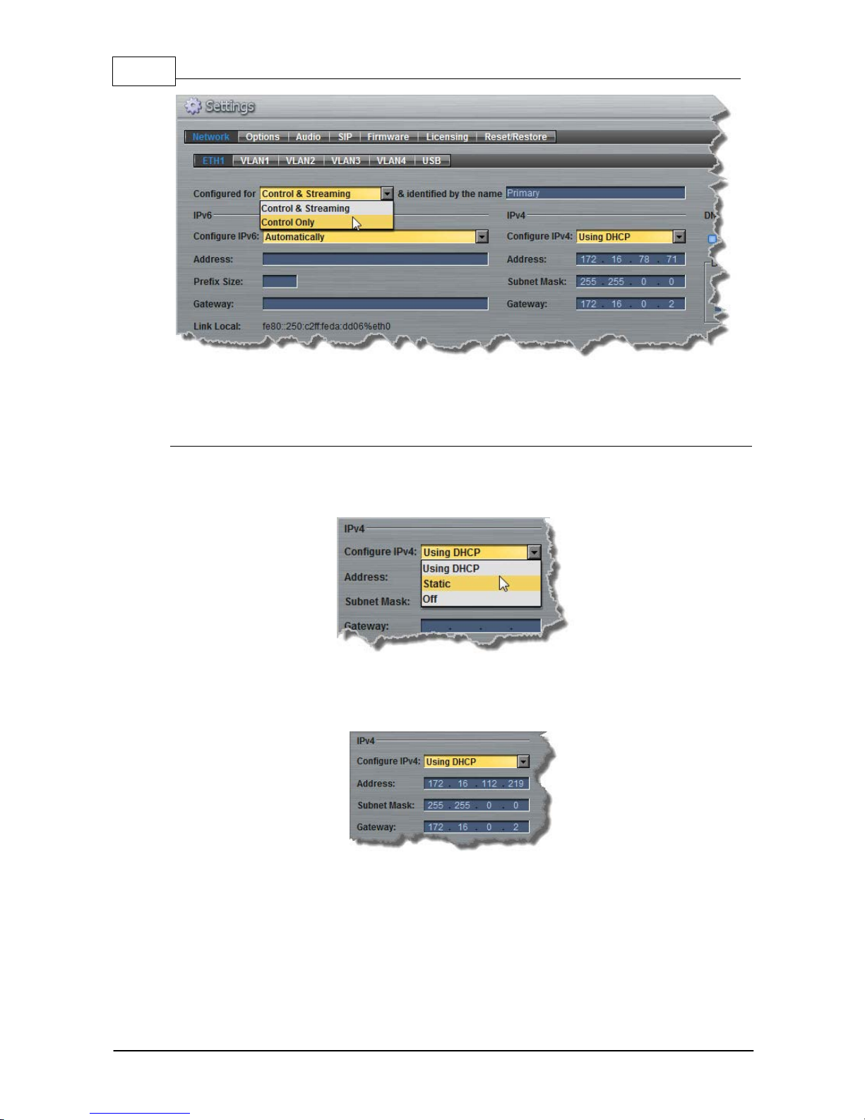
66 Bridge-IT M anua l
© Tieline Pty. Lt d. 2015
The name entered into the right-hand text box, e.g. Primary or Secondary, is an interface identifier
used when configuring new programs via the Programs panel.
IPv4 Address Configuration
The codec is capable of automatic DHCP address assignment, or manually configured static IPv4
address configuration via the drop-down Configure IPv4 menu. If you want to ignore IPv4 settings
select Off.
DHCP IP addresses are automatically assigned and can change each time you connect to your
Internet Service Provider or to your own local area network (LAN). By default the codec is configured
for DHCP-assigned IP addresses.
Static IP addresses are fixed addresses that are recommended for studio installations, so that IP
address dialing remains the same over time for incoming codec connections.
Page 67
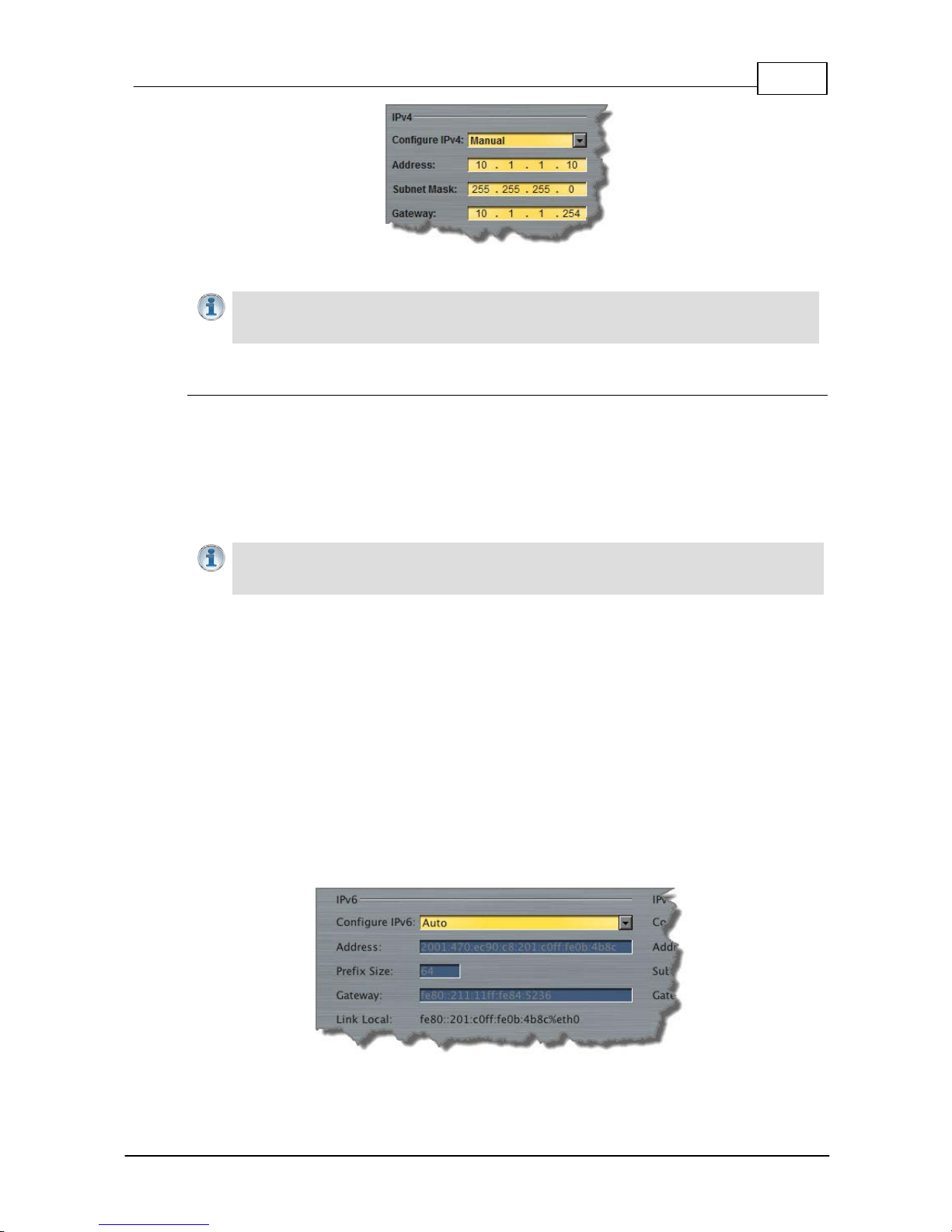
67
© Tieline Pty. Lt d. 2015
Bridge-IT M anua l
Click Save Settings to store all configuration settings.
Note: The Subnet Mask is used by the TCP/IP protocol to determine whether a host is on
the local subnet or on a remote network. The default Gateway is the router linking the
codec's subnet to other networks . See y our IT administ rator for more details .
IPv6 Address Configuration
An IPv6 address is represented by 8 groups of 16-bit hexadecimal values separated by colons (:).
The drop-down Configure IPv6 menu provides three address configuration options:
1. Auto: An address is automatically assigned to the codec when you connect the codec to an
IPv6 router. This process is similar to how an IPv4 DHCP address is assigned.
2. Manual: Select to enter static IPv6 address details.
3. Off: Select to ignore IPv6 address details.
Important Note: Select Off in the drop-down Configure I P v6 menu if you are not using
IPv6 to connect to another device. This ensures your codec will attempt t o c onnect us ing
IPv4 at all ti mes .
Types of I Pv6 Addresses
There are two types of addresses displayed in the IPv6 section:
1. IPv6 address (normally global): A router-allocated IP address with 'global' visibility,
details of which are displayed in the Address, Prefix and Gateway text boxes.
2. Link Local Address: A local address which can only be used to connect to another
device directly over a LAN. This address is allocated by the codec internally based on
MAC address details.
Auto A ddress Assignment
By default the codec is programmed for connecting to an IPv6 router which automatically
allocates IPv6 address details, as displayed in the following example.
Page 68
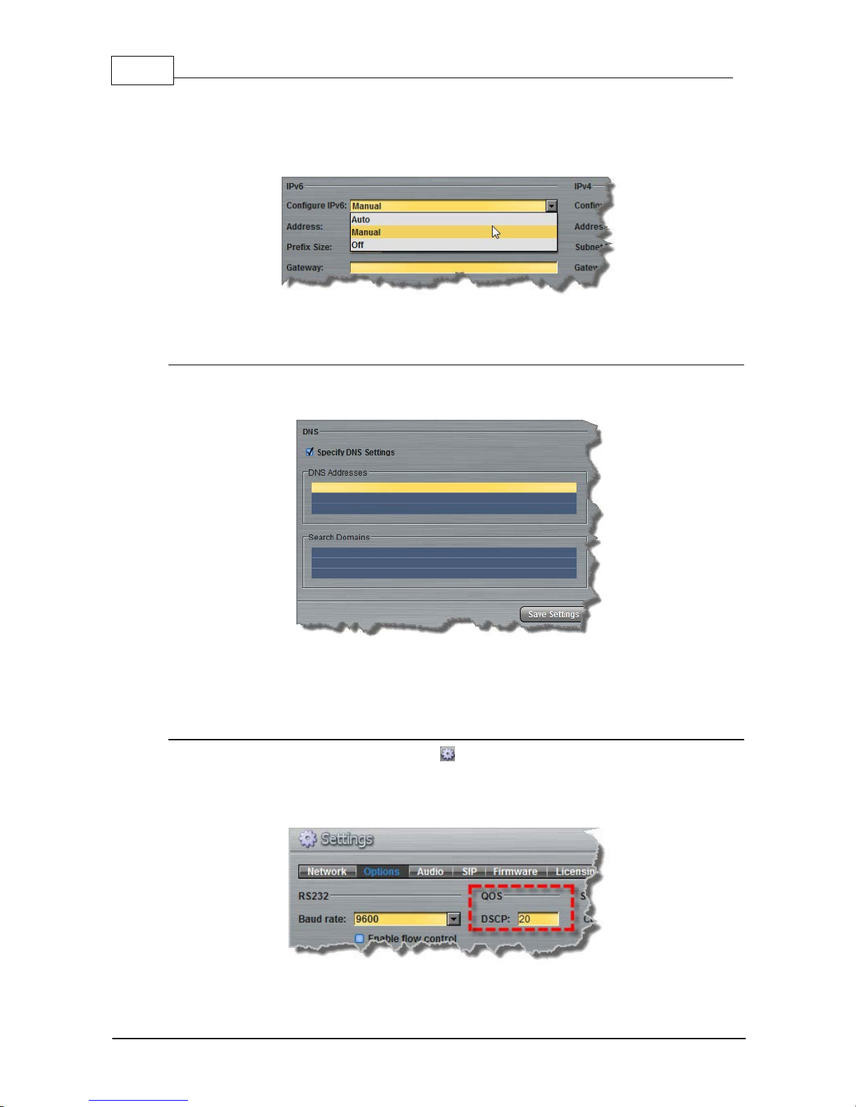
68 Bridge-IT M anua l
© Tieline Pty. Lt d. 2015
Manual IPv6 Address Assignment
To configure IPv6 address details into the codec manually, select Manual and enter details into
the Address, Prefix and Gateway text boxes.
Click Save Settings to store all configuration settings.
Specifying DNS Settings
It is possible to specify Domain Name Server (DNS) settings to allow easy look up of codecs within
the specified DNS Addresses or Domains.
The codec can be configured to tag IP data packets sent across a network by entering a value into
the Differentiated Services Code Point (DSCP) field within the header of data packets transmitted
over the network.
Configuring QoS
1. Open the web-GUI and click the Settings symbol at the top of the screen to display the
Settings panel.
2. Click the Options button at the top of the Settings panel.
3. Click in the QoS text box and enter the new value.
4. Click the Save Settings button at the bottom of the panel to save the new setting.
Page 69
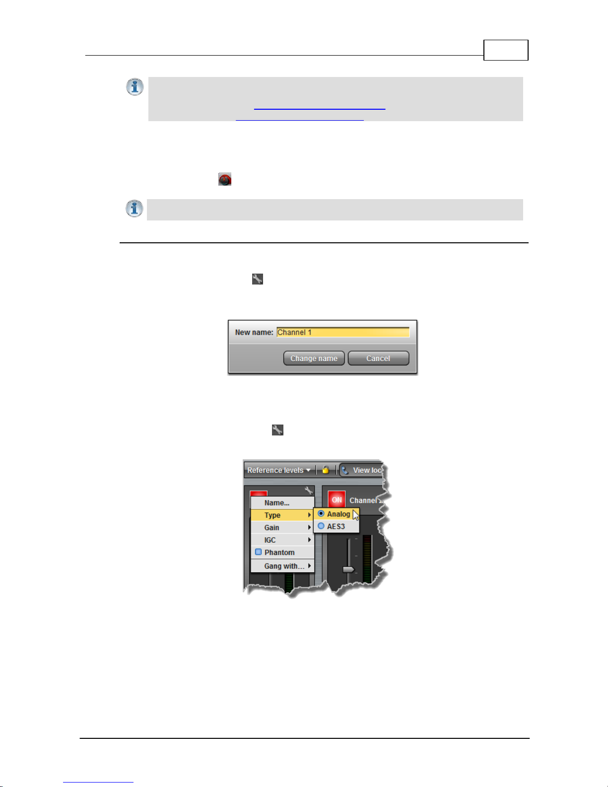
69
© Tieline Pty. Lt d. 2015
Bridge-IT M anua l
Importa n t Note: Check with your IT administ rator before changing this s ett i ng. By default
the codec is programmed for As s ured Forwarding and more details about DSCP are
available on Wikipedia at http://en.wikipedia.org/wiki/Dscp. For more information on
configur ing QoS see Configuring QoS for Broadcast s in this manual.
16.2 Configuring Input/Output Settings
Click the Inputs button to view input controls available within the Toolbox web-GUI.
Importa n t Note: 15 volt phantom power can only be supplied on analog input 1; this is
disabled by def ault.
Configuring Input Channel Setti ngs
Renaming Input Channels:
1. Click the Input Settings symbol on the input channel you want to rename.
2. Select Name and click in the text box to edit or enter a new name.
3. Click Change Name to confirm the name change.
Selecting Analog and Digital A udio Sources:
Codec inputs are configured for analog high-gain mic level audio sources by default.
1. Click the Input Settings symbol.
2. Select Type and click to select either Analog or AES3.
3. When you select AES3, the display changes to reflect 100% input levels; slider and
input on/off controls are locked on.
Page 70
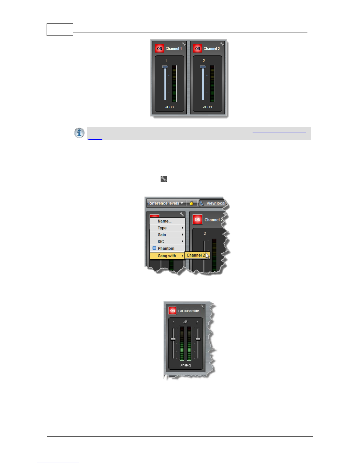
70 Bridge-IT M anua l
© Tieline Pty. Lt d. 2015
Importa n t Note: Input levels can only be adjusted on analog inputs. See Configuring AES 3
Audio for more information about the digital inputs and outputs.
Ganging Channels:
Ganging is useful because it allows you to adjust the audio level of both inputs simultaneously.
1. Click the Input Settings symbol on either channel.
2. Select Gang and click to either gang or ungang channels.
3. When ganged, the two channel sliders move in sync with each other when dragged
using a mouse-pointer.
4. Click the Link symbol to temporarily disable the ganging function and fine-tune channel
audio levels. Click the Link symbol again to resume ganging.
Page 71
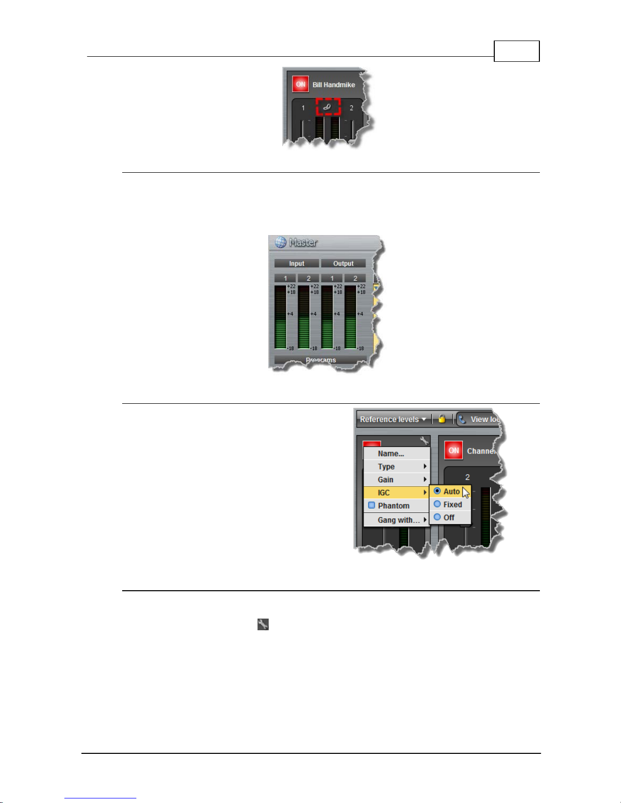
71
© Tieline Pty. Lt d. 2015
Bridge-IT M anua l
Setting Analog A udio Levels
Audio levels on the Input panel should be set to ensure audio peaks average at the first yellow
indications on the PPM meters, which represents +4dBu. These levels should also be checked
against the Input PPM Meters on the Master panel. When the codec is not connected the Master
panel will display the input audio going to the outputs (default setting).
Other I nput Controls
Adjust the IGC (Intelligent Gain Control) input
settings to Auto, Fixed or Off as required.
Channel 1 Phantom Power
Input 1 can be configured to supply 15 volt phantom power if required; this is disabled by default.
1. Click the Input Settings symbol on channel 1.
2. Click to select the Phantom check box.
Page 72
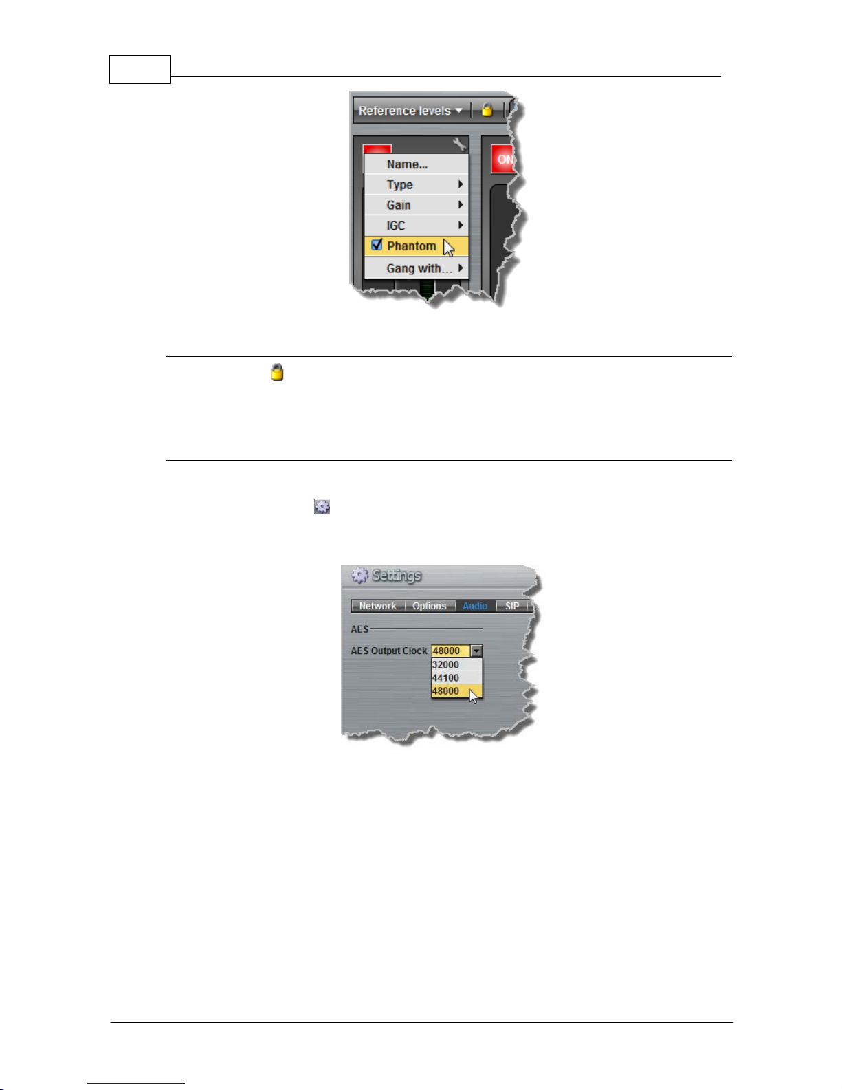
72 Bridge-IT M anua l
© Tieline Pty. Lt d. 2015
Locking Input Settings
1. Click the Lock symbol to lock all Input panel settings.
2. When locked, the Input panel is greyed out and the lock symbol appears in the bottom-left
corner. Note: the lock function does not affect the codec front panel controls.
AES3 Output Sample Rate Confi gurati on
The AES3 output sample rate can be configured using the Toolbox web-GUI.
1. Click the Settings symbol at the top of the screen to open the Settings panel.
2. Click the Audio tab and use the drop-down menu to select your preferred AES Output Clock
setting, then click Save Settings.
Page 73
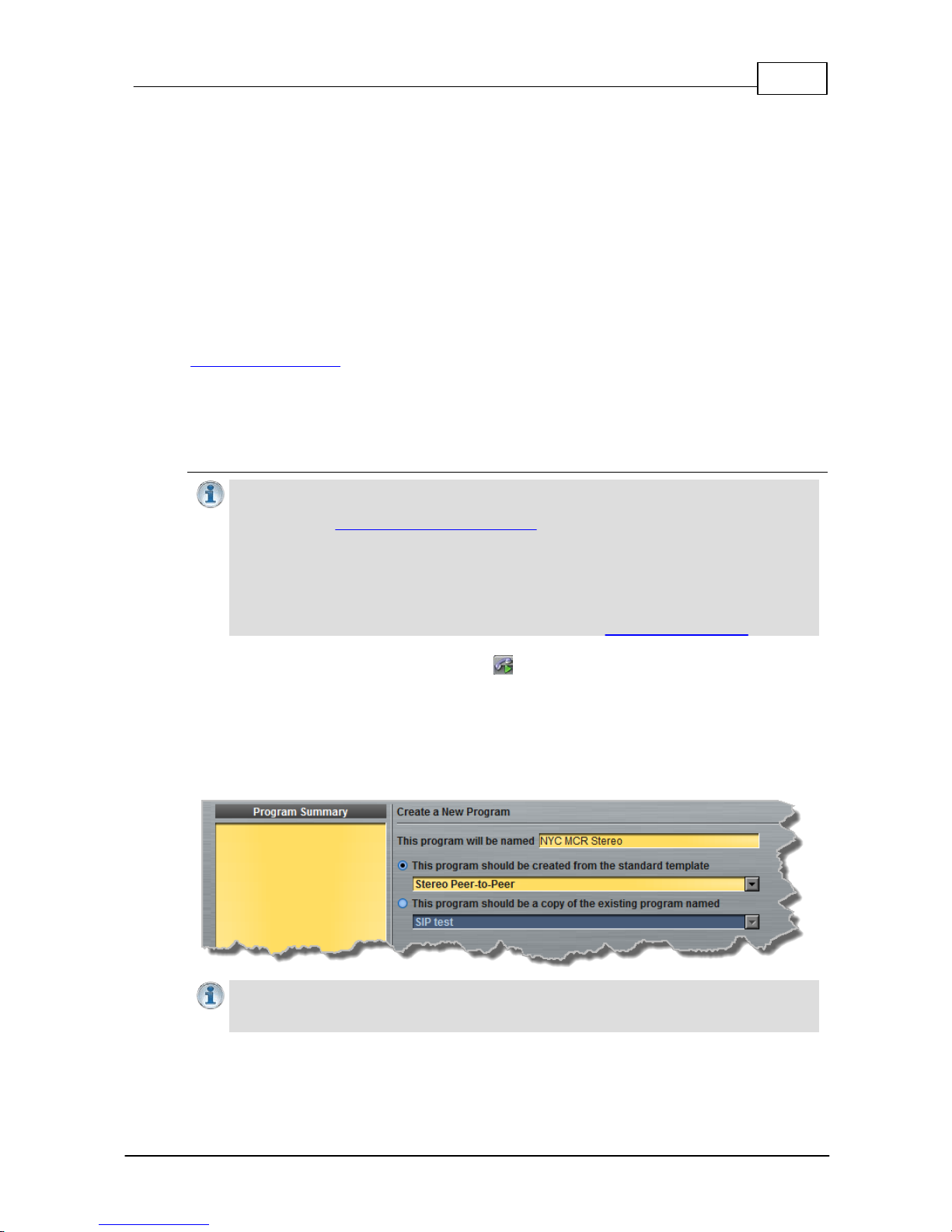
73
© Tieline Pty. Lt d. 2015
Bridge-IT M anua l
16.3
Configuring Mono or Stereo Peer-to-Peer Programs
The Programs panel incorporates a wizard to configure a new program and all audio stream
settings. Before you configure a new codec program consider if:
· You want your codec to be capable of dialing and answering, dialing only or answering only.
· A backup connection is required.
This section contains instructions for:
1. Configuring Peer-to-Peer Programs: Dialing and Auto reconnect
2. Configuring Answering Connections
For more information about programs and audio streams within programs see the section titled
About Program Dialing. Note: The following connection setup instructions will display how to
configure a dial and answer program, with a backup connection. If you want the codec to either dial
or answer only, select the option and the wizard will automatically display relevant screens to allow
you to configure the codec correctly.
Configuring Peer-to-Peer Programs: Diali ng
Importa n t Notes: Before you st art program configuration please note:
· You cannot edit a program when it is currently loaded in the codec.
· You can lock a loaded custom program in a codec to ensure the currently loaded
program type cannot be unloaded by a codec dialing in with a different program type.
· Some drop-down menus and settings may be greyed out intentionally depending on
features available.
· It is possible to save a program at several points throughout the program wizard and
use default settings to save configuration time.
· T o learn more about programs see the section titled About Program Dialing.
1. Open the web-GUI and click the Programs symbol at the top of the screen to display the
Programs panel.
2. Click the New Program button to open the wizard and:
· Click in the text box to name the new program.
· Select Mono/Stereo Peer-to-Peer, or if you want to use an existing program as a template,
select this option. Then click Next.
Importa n t Notes: When you decide to use an existing program as a template, t he new
program inherits all t he set t ings of the template program and you can adjust t hese s ett ings
as required by continuing through the program wizard.
3. Enter a name for the Audio Stream and configure the codec to dial, answer or dial and answer.
Then click Next.
Page 74
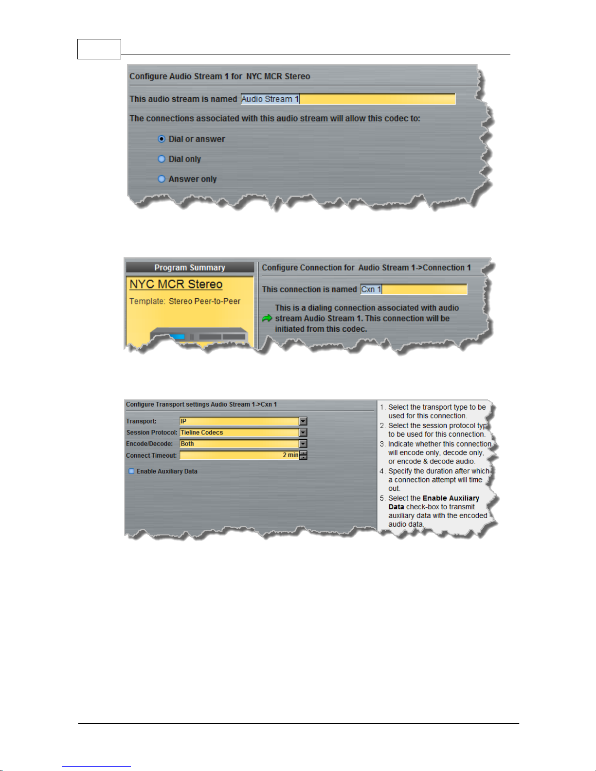
74 Bridge-IT M anua l
© Tieline Pty. Lt d. 2015
4. This audio stream connection in the wizard will allow the codec to dial. Enter the name of the
connection in the text box, then click Next.
5. Follow the instructions on the right-hand side of the panel to configure the transport settings for
the connection, then click Next.
Page 75
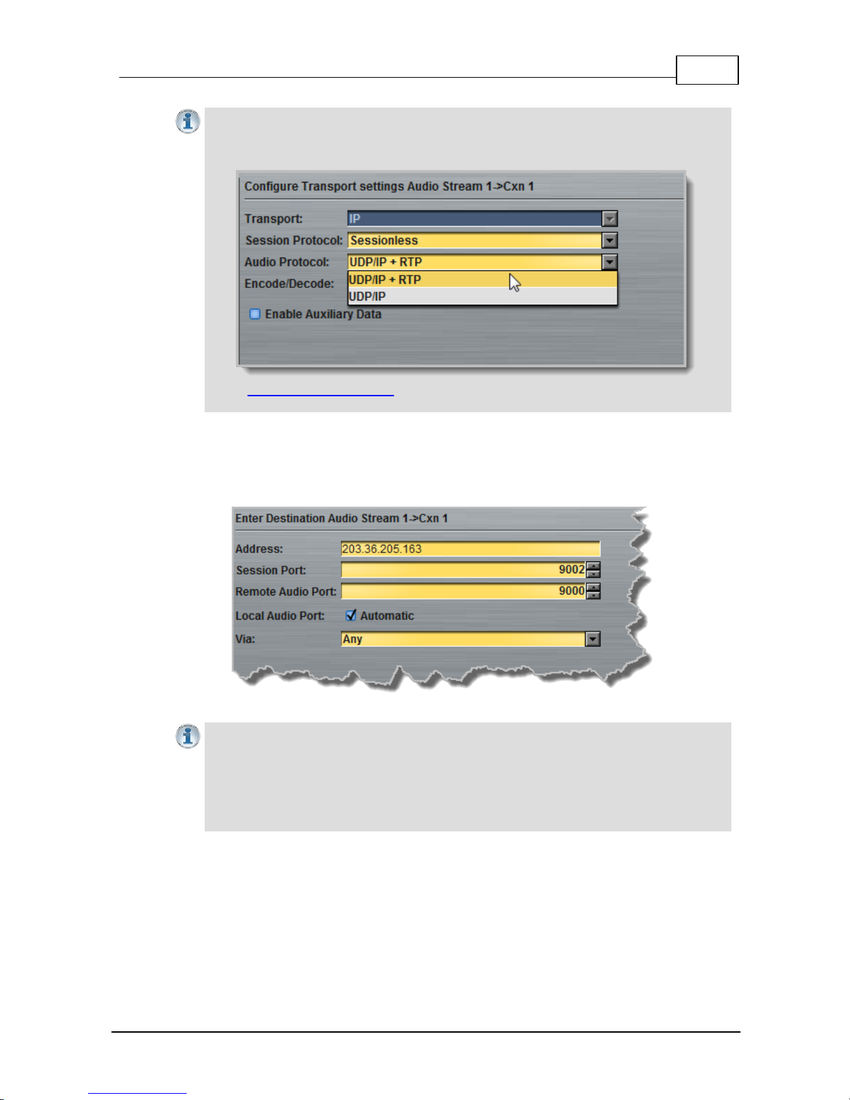
75
© Tieline Pty. Lt d. 2015
Bridge-IT M anua l
Importa n t Notes:
· If you select Sessionless as the Sessi on Protocol select UDP/I P + RTP for RFC-
compliant IP st reaming.
· See RS232 Data Configuration for detailed information on RS232 data and see "E nabling
Relays and RS232 Data" for more information on relay operations.
6. Configure the IP address, ports, and then specify which streaming interface is used to dial this
connection, e.g. Primary (LAN / ETHERNET port) or VLAN if configured. VLANs can be used to
configure separate control and streaming interfaces if required. Note: By default Any will select
Primary as the streaming interface.
Importa n t Notes: The Rem ote Audi o P ort is t he c odec port at the remote end of the link
to which you are sending audio. The Local Audio Po rt is t he port used by the local codec
to receiv e audio from the remote codec. When Ti eli ne Codecs is the Sessi on P rotocol
selected (using Tieline sesssion data), the Local Audi o P ort is automat ic ally configured as
UDP audio port 9000 by default. This is t he default audio port used by all Tieline IP codecs
for the first audio stream connection. Click to deselect the Automatic c heck -box t o change
this s et t ing.
When you select Sessionless as the Session Protocol the Session Port is not configurable and
you can manually configure the Remote Audio Port and Local Audio Port.
Page 76
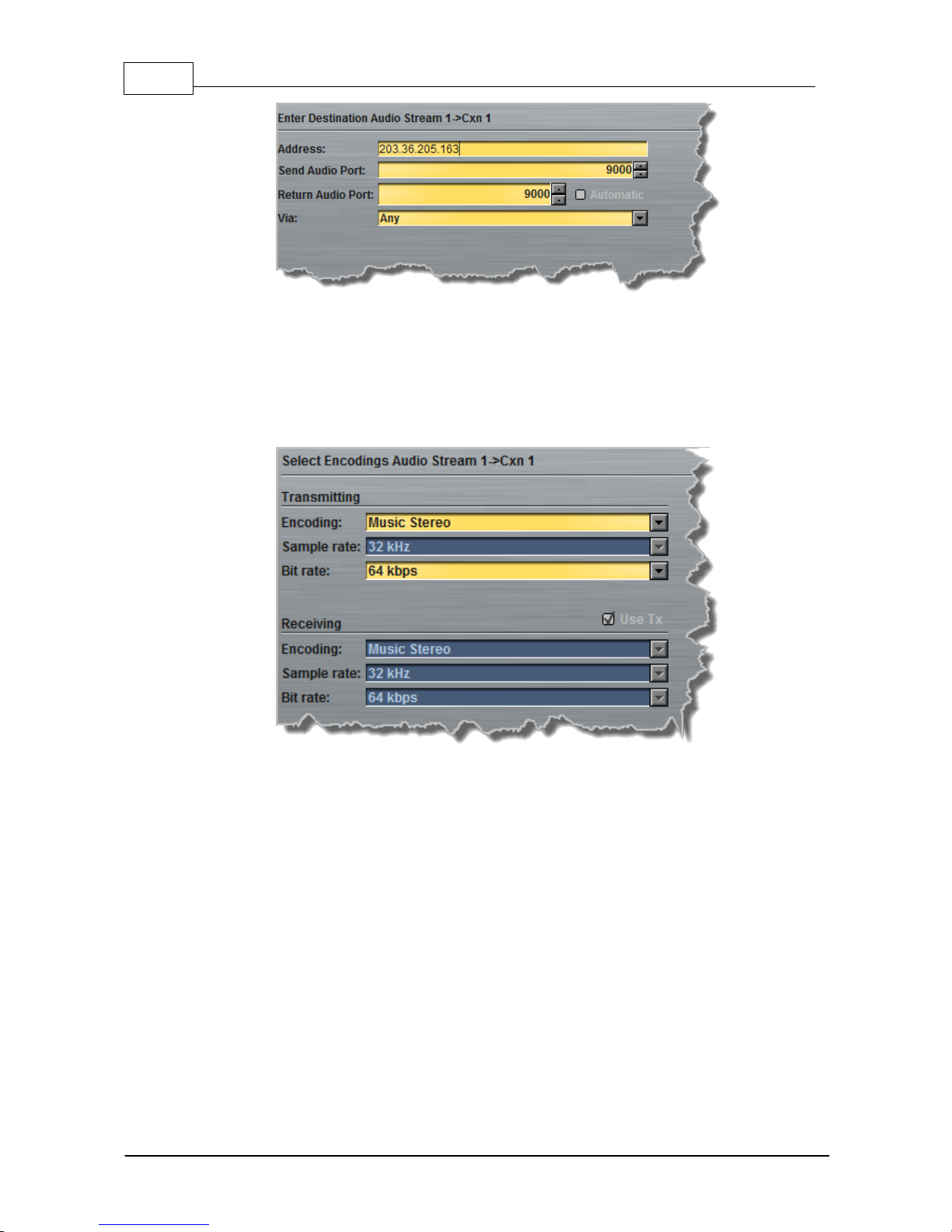
76 Bridge-IT M anua l
© Tieline Pty. Lt d. 2015
7. Click Save Program to save the program with the default algorithm, jitter and FEC settings
which are physically entered in the codec. Alternatively, click Next to specify individual
algorithm, jitter buffer and FEC settings for this audio stream (recommended).
8. Click the drop-down arrows on the right-hand side of each text box to adjust the Encoding,
Sample rate and Bit rate options, then click Next.
9. For IP connections click to configure:
· Auto Jitter Adapt and the preferred auto jitter setting using the drop-down arrow for Buffer
priority, or
· Fixed Buffer Level and enter the Jitter Depth (5000ms maximum).
· Local and Remote FEC settings if required.
Page 77
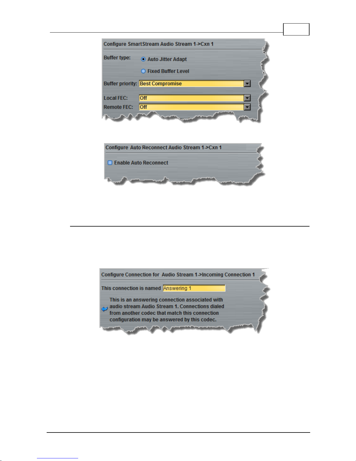
77
© Tieline Pty. Lt d. 2015
Bridge-IT M anua l
10.Click Save Program or click Next to Enable Auto Reconnect.
11.Click Save Program to complete configuration of a dialing only program, or click Next to
configure an answering connection
Configuring Answering Connections
The codec is capable of being configured to use specific settings when answering calls. This useful
to configure the answering codec with appropriate jitter buffer and FEC settings to suit the prevailing
conditions at the codec's location:
1. Enter a name for the answering connection and click Next.
2. Follow the instructions on the right-hand side of the panel to configure the Transport,
Session Protocol and Audio Port settings for the connection, then click Next.
Page 78
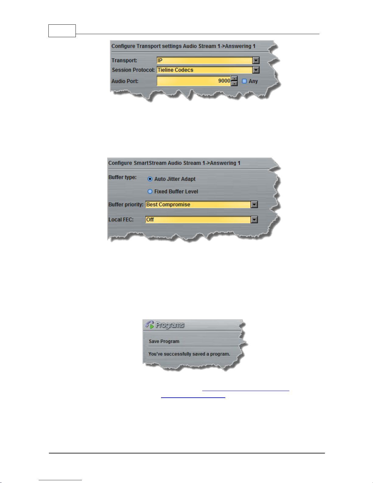
78 Bridge-IT M anua l
© Tieline Pty. Lt d. 2015
3. Click to configure jitter buffer and FEC settings:
· Auto Jitter Adapt and the preferred auto jitter setting using the drop-down arrow for
Buffer priority, or
· Fixed Buffer Level and enter the Jitter Depth, which must be between 12ms and
5000ms depending on the algorithm you select.
· Local and Remote FEC settings if required.
4. After configuring these settings there are 3 options:
i. If you want to create another answering connection, select the check-box for Create
another answering connection at the bottom of the panel and continue through the
wizard.
ii. Click Next and select Enable File Playback on silence detection.
iii.Click Save Program to save the program at this point.
When you save the program it will be confirmed by the following message.
5. Click Finish and the newly created program will be displayed in the left pane within the
Programs panel and in the Master panel. Select and connect audio streams in a program
using the Master panel, or dial the program manually using the codec front panel.
Page 79
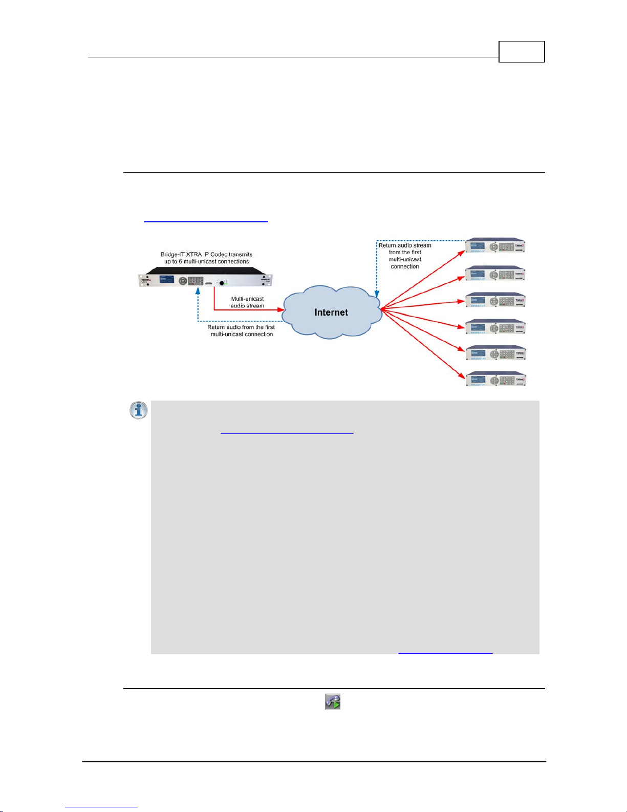
79
© Tieline Pty. Lt d. 2015
Bridge-IT M anua l
16.4
Configuring Multi - Unicast Dialing Programs
The codec can transmit a mono or stereo multi-unicast audio stream to a maximum of 6 endpoints
in total. The first connection in a multi-unicast program is capable of bidirectional audio. Multiunicast connections can only be created using the ToolBox web-GUI and require a software license
which supports multi-unicasting.
Prerequisites:
· Bridge-IT firmware v.1.01.00 r4219 or higher.
· G3 codec firmware v.1.6.56 or higher (if connecting to a G3 codec).
· ToolBox web-GUI v.1.2.2.3 or higher.
· A multi-unicast license installed in the dialing codec.
Importa n t Notes: Before you st art program configuration please note:
· You cannot edit a program when it is currently loaded in the codec.
· You can lock a loaded custom program in a codec to ensure the currently loaded
program cannot be unloaded by a codec dialing in with a different program type.
· If you are dialing to both G3 and Bridge-IT, Merlin or Genie codecs, by default the
Audio Reference Level will be configured for the compatibility of the codec dialed first.
I.e. if you dial a G3 codec first then the G3 Audio Reference Level will be configured for
all connections.
· Connections are dial only for multi-unicast programs.
· Some drop-down menus and settings may be greyed out intentionally depending on
features available.
· It is possible to save a program at several points throughout the program wizard and
use default settings to save configuration time. The first connection in each multiunicast stream determines default settings (e.g. algorithm, sample rate, bit rate), for
all subsequent connections in that stream, except for dialing settings.
· Select any algorithm for multi-unicast connections except aptX Enhanced and PCM.
· Bidirectional audio is only available on the first connection dialed.
· Forward Error Correction (FEC) is not available on multi-unicast connections.
· Renegotiation of connection bit rates is not possible when connected.
· Ensure you have sufficient connection bandwidth at the local codec to support all the
connections to which you are connecting.
· T o learn more about programs see the section titled About Program Dialing.
Creating a Multi - Unicast Program
1. Open the web-GUI and click the Programs symbol at the top of the screen to display the
Programs panel.
Page 80
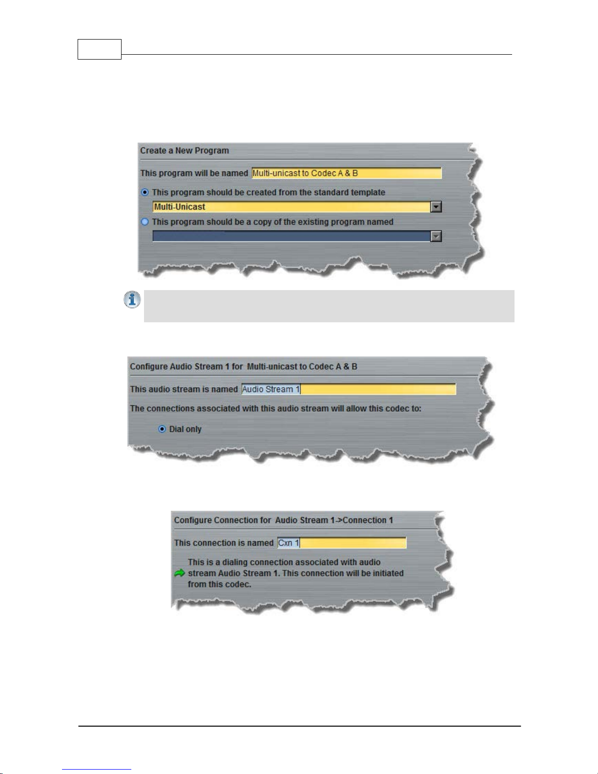
80 Bridge-IT M anua l
© Tieline Pty. Lt d. 2015
2. Click the New Program symbol to open the wizard and then:
· Click in the text box to name the new program.
· Select Multi-unicast, or if you want to use an existing program as a template, select this
option. Then click Next. Note: In this example we are creating a Multi-unicast program to dial
2 end points.
Importa n t Note: When you decide to use an existing program as a template, t he new
program inherits all t he set t ings of the template program and you can adjust t hese s ett ings
as required by continuing through the program wizard.
3. Enter a name for the Audio Stream and then click Next.
4. This audio stream connection in the wizard will allow the codec to dial. Enter the name of the
connection in the text box, then click Next.
5. Follow the instructions on the right-hand side of the panel to configure the transport settings for
the connection, then click Next. Note: only the first connection dialed in a multi-unicast program
can encode and decode audio. All other connections are unidirectional and encode only.
Page 81
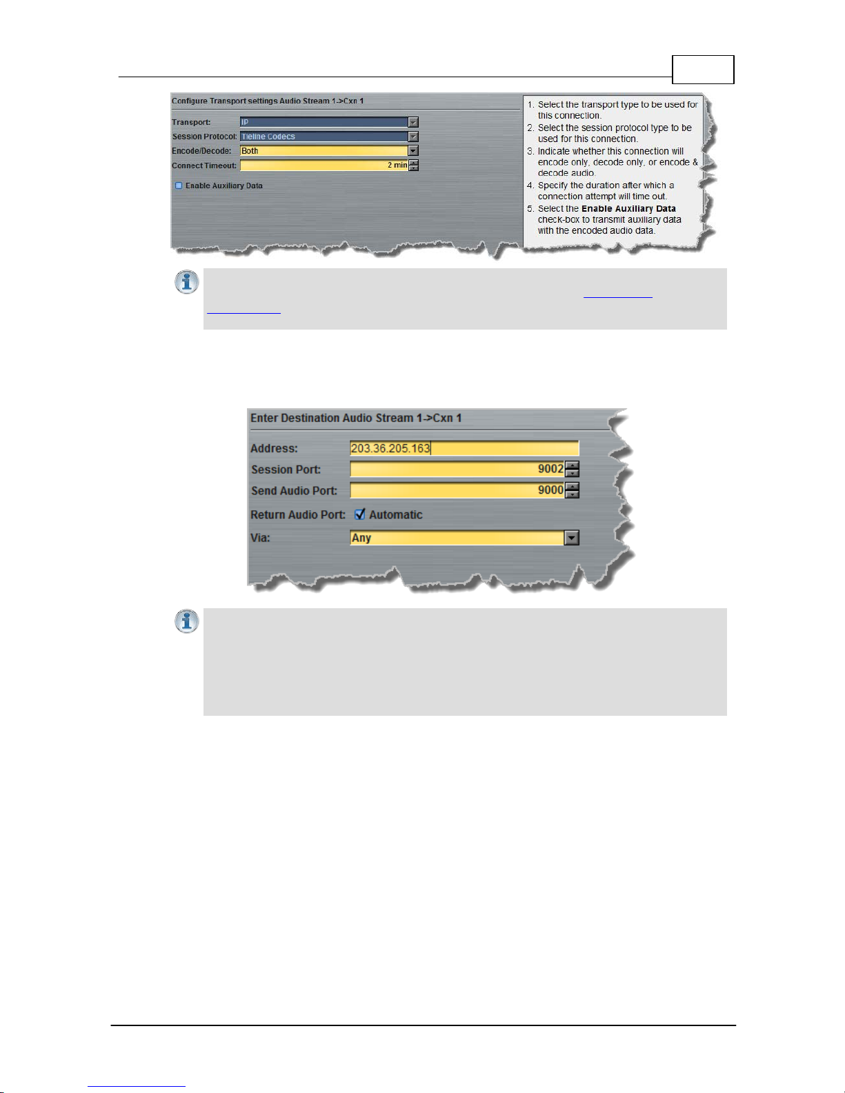
81
© Tieline Pty. Lt d. 2015
Bridge-IT M anua l
Importa n t Note: Auxili ary IP data connections are not possible between the codec and G3
Command e r and i-Mix codecs over multi-unicast connections. See RS232 Data
Configuration for detailed information on RS232 data and see "Enabling Relays and RS232
Data" for more information on relay operations.
6. Configure the IP address, ports, and then specify which streaming interface is used to dial this
connection, e.g. Primary (LAN / ETHERNET port and default setting) or VLAN if configured.
Note: By default Any will select Primary.
Importa n t Notes: The Rem ote Audi o P ort is t he c odec port at the remote end of the link
to which you are sending audio. The Local Audio Po rt is t he port used by the local codec
to receiv e audio from the remote codec. When Ti eli ne Codecs is the Sessi on P rotocol
selected (using Tieline sesssion data), the Local Audi o P ort is automat ic ally configured as
UDP audio port 9000 by default. This is t he default audio port used by all Tieline IP codecs
for the first audio stream connection. Click to deselect the Automatic c heck -box t o change
this s et t ing.
Click Save Program to save the program with the default algorithm, jitter and FEC settings which
are physically entered in the codec. Alternatively, click Next to specify individual algorithm, jitter
buffer, FEC and auto reconnect settings for this audio stream (recommended).
7. Click the drop-down arrows on the right-hand side of each text box to adjust the Encoding,
Sample rate or Bit rate options.
Page 82
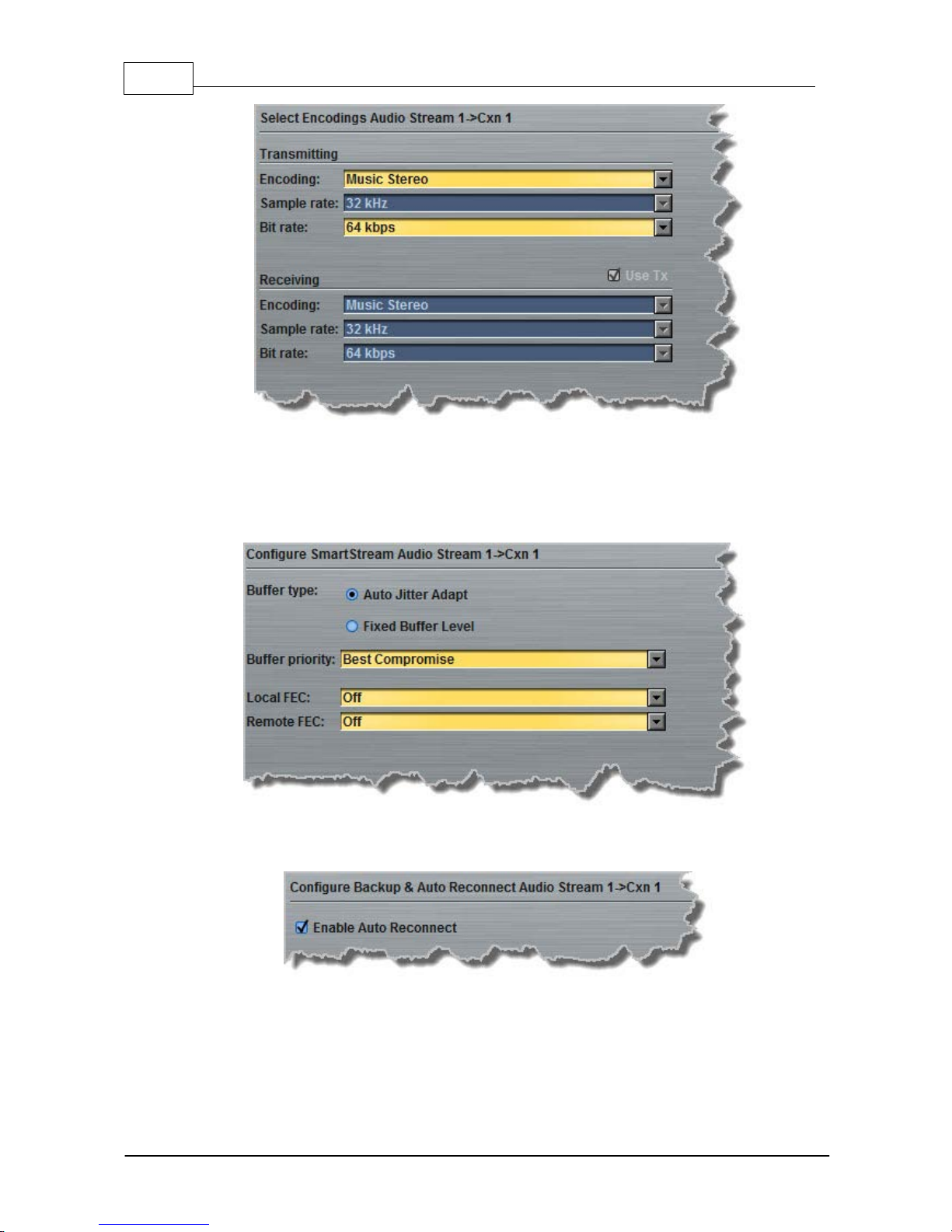
82 Bridge-IT M anua l
© Tieline Pty. Lt d. 2015
Click to configure:
· Auto Jitter Adapt and the preferred auto jitter setting using the drop-down arrow for Buffer
priority, or
· Fixed Buffer Level and enter the Jitter Depth (5000ms maximum).
· Local and Remote FEC settings if required.
8. Select the Enable Auto Reconnect check-box if you want to enable this feature. This is enabled
by default.
9. Select the Create another dialing connection check-box to configure a new connection for an
additional endpoint, then click Next.
Page 83
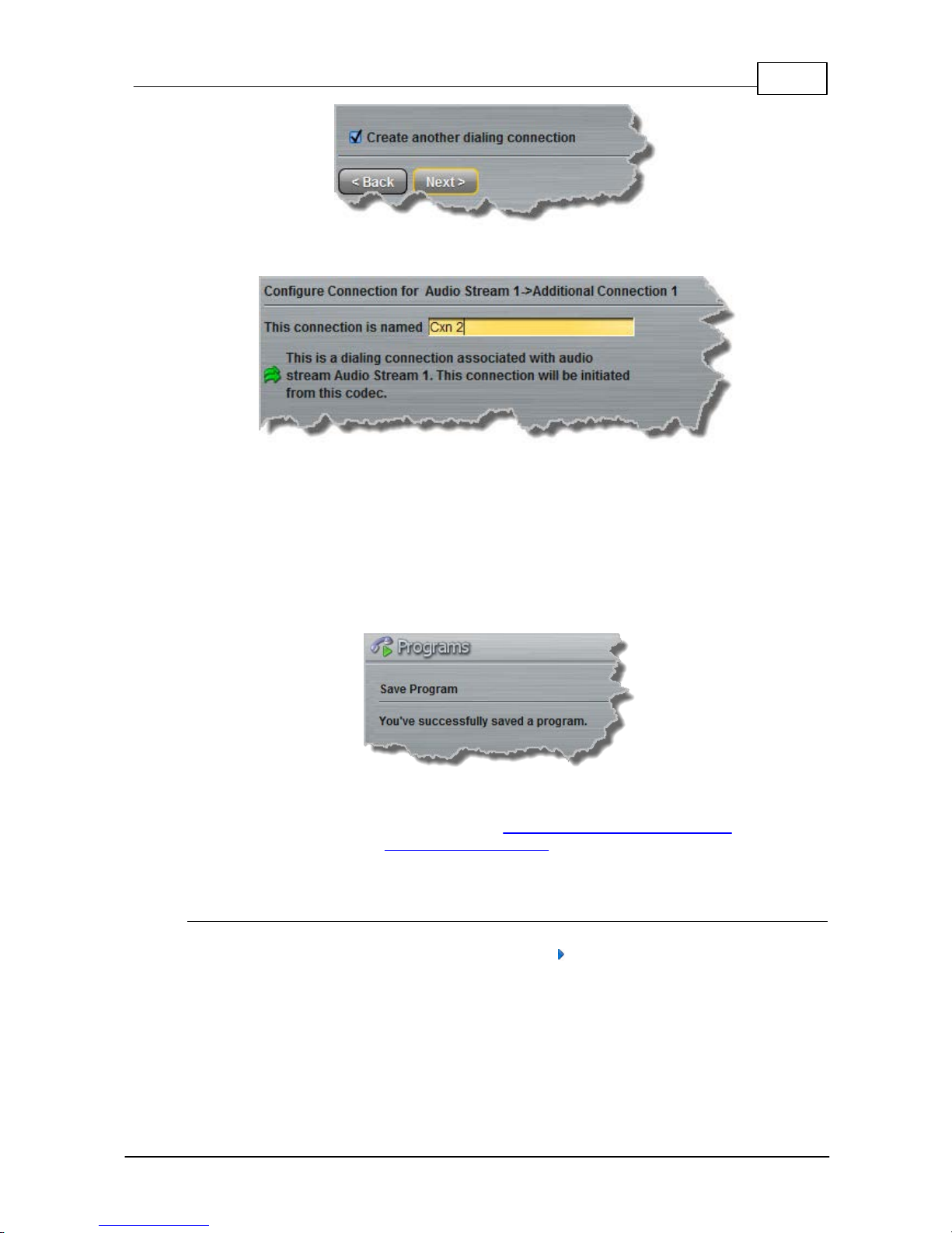
83
© Tieline Pty. Lt d. 2015
Bridge-IT M anua l
10.Enter the name of the second connection in the text box, then click Next.
11.Continue through the program wizard and configure all multi-unicast connections in a similar
manner.
12.After configuring all connections there are 2 options:
i. Click Next and select Enable File Playback on silence detection.
ii. Click Save Program to save the program.
When you save the program it will be confirmed by the following message.
13.Click Finish and the newly created program will be displayed in the left pane within the
Programs panel and in the Master panel. Select and connect audio streams in a program
using the Master panel, or dial the program manually using the codec front panel.
Monitori ng Mult i - Unicast Programs
The Master panel in the ToolBox web-GUI is used to monitor connection details and view PPMs,
as displayed in the following image. Click the blue arrow in the Program/Cxn column to expand
and minimize connection details (as displayed below).
Page 84
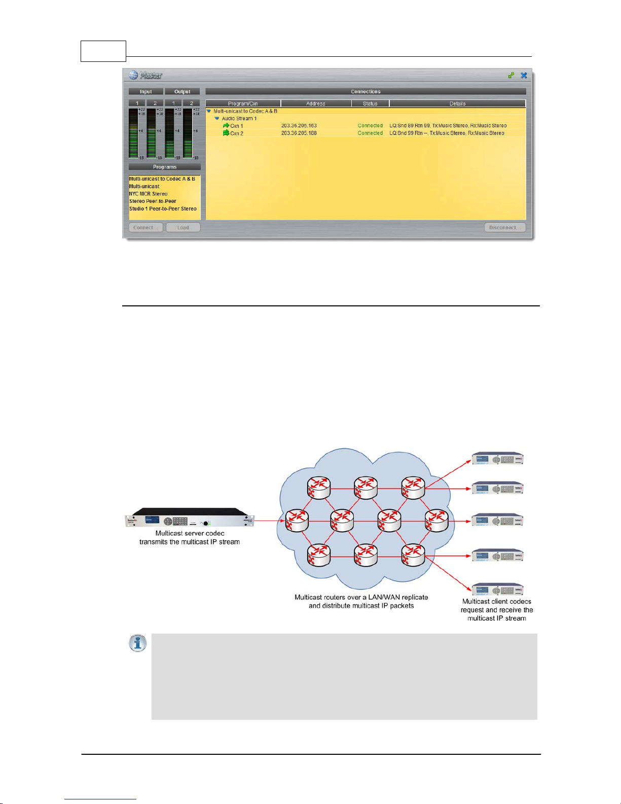
84 Bridge-IT M anua l
© Tieline Pty. Lt d. 2015
16.5 Configuring Multi cast Server Programs
How Mult i casti ng Works
Multicast transmissions are sent using a dedicated IP multicast address that looks similar to a
regular IP address and multicast subscribers request transmissions from this address. This unique
address allows multicast routers to identify multicast requests from a group of codecs interested in
a particular transmission and packets are replicated depending on demand. This can create large
demands on network bandwidth if the multicast group is significant in size.
As a result, only small sections of the internet are multicast enabled and many internet service
providers (ISPs) block multicast traffic over wide area networks. This restricts most multicast
broadcasts to private local area networks. Some ISPs provide quality of service (QoS) priority to
multicast streams for an increased service charge. You need to check with your ISP to find out what
multicast services, if any, are available over WANs.
Importa n t Notes:
· When a connecti on is dialed Tieline codecs normally use ses sion data to c onfigure
sett ings li k e the algorithm, connection bit rate and sample rate etc. Multicast c onnections
are sessionless and do not use Tieline session data. As a result, it i s im perative t hat all
codecs are configured with the same connection setti ngs prior to connecting, or they will
not be able to join multicast streaming sessions.
· Automatic or fixed jitter buffer set t ings c an be adjusted on individual client codecs as
Page 85

85
© Tieline Pty. Lt d. 2015
Bridge-IT M anua l
required. There is no jitter buffer sett ing on the server codec because it never receives
audio pack ets .
Prerequisites:
· Bridge-IT firmware v.1.01.00 r4219 or higher.
· G3 codec firmware v.1.6.56 or higher (if connecting to a G3 codec).
· ToolBox web-GUI v.1.2.2.3 or higher.
· A multi-unicast license installed in the dialing codec (Note: the Multi-Unicast license includes
multicast server capability).
· Use firmware higher than 2.8.xx in the Bridge-IT, Genie and Merlin families of codecs to transmit
auxiliary data.
Multi cast Server versus Mul ti cast Cli ent Programs
Two different types of multicast programs need to be created when multicasting:
· A multicast server program is used by the broadcasting codec to send multicast IP packets
to multicast routers on a network.
· A multicast client program is used by codecs to receive multicast IP audio packets.
A multicast server codec sends audio packets only and a multicast client codec receives audio
packets only. Codecs using the client program request multicast packets (sent from the server
codec), which are distributed by multicast routers.
Creating Multi cast Server Programs
Importa n t Notes: Before you st art program configuration please note:
· Ensure all connection related settings like the port, algorithm, bit rate (etc) match on
both multicast server and client programs or they will not connect successfully.
· You cannot edit a program when it is currently loaded in the codec.
· You can lock a loaded custom program in a codec to ensure the currently loaded
program cannot be unloaded by a codec dialing in with a different program type.
· Some drop-down menus and settings may be greyed out intentionally depending on
features available.
· It is possi ble to save a program at several points t hroughout t he program wizard and
use default sett i ngs t o save configuration time.
· To learn more about programs see the section tit led "A bout Program Dialing".
· Always dial the multicast server codec connection first before connecting multicast
client codecs.
· Multicast client codecs will display return link quality (LQ) only. The Return reading
represents the audio being downloaded from the network locally. Multicast server
codecs do not display LQ readings.
· The default UDP audio port setting is 9000 for a multicast and the client and server port
settings must match.
· Forward Error Correction (FEC) is not available for multicast connections.
· It is not possible to connect to a G3 codec and receive multicast IP audio streams.
· To copy multicast client programs onto multiple codecs see Backup and Restore
Configuration Files.
1. Open the web-GUI and click the Programs symbol at the top of the screen to display the
Programs panel.
2. Click the New Program button to open the wizard and:
· Click in the text box to name the new program.
· Select Multicast Server or if you want to use an existing program as a template, select
Page 86
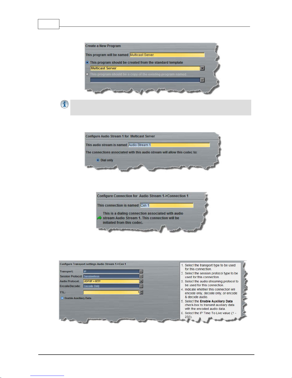
86 Bridge-IT M anua l
© Tieline Pty. Lt d. 2015
this option. Then click Next.
Importa n t Notes: When you decide to use an existing program as a template, t he new
program inherits all t he set t ings of the template program and you can adjust t hese s ett ings
as required by continuing through the program wizard.
3. Enter a name for the Audio Stream, then click Next.
4. This audio stream connection in the wizard will allow the codec to dial. Enter the name of the
connection in the text box, then click Next.
5. Follow the instructions on the right-hand side of the panel to configure the transport settings for
the connection, then click Next. Note: select UDP/IP +RTP for RFC-compliant streaming. If
auxiliary data is enabled the audio stream will not be RFC-compliant.
Page 87
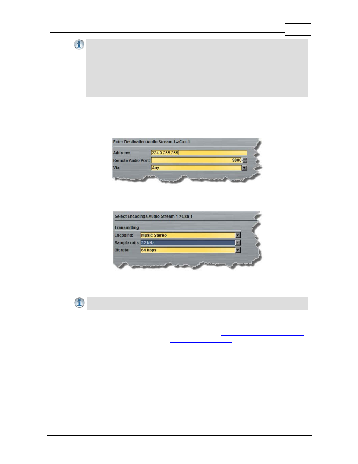
87
© Tieline Pty. Lt d. 2015
Bridge-IT M anua l
Importa n t Notes:
· T he encode and decode direction is configured automatically for Encode Onl y (server
prog ram) or De code Onl y (cli ent program). This setti ng is c onfigured when you select
either Multica st Server or Mul tica st Cli ent when you first create the program in the
wizard.
· The TTL value you need to use is dependent upon your network infrastruct ure. Please
consult y our network administrator if you are unsure about how to configure this s ett ing.
· Use firmware higher than 2.8.x x i n the Bridge-IT, Genie and Merlin families of codecs to
enable auxiliary data.
6. Configure the multicast IP address and Remote Audio Port (the same multicast address and
port must be used for both the server and client programs), then specify which IP streaming
interface is used to dial this connection, e.g. Primary (LAN / ETHERNET port and default setting)
or VLAN if configured. Note: By default Any will select Primary.
7. Click the drop-down arrows on the right-hand side of each text box to select the Encoding,
Sample rate, Bit rate or Sample size options. Click Next to continue.
8. Click to select Enable Auto Reconnect to enable automatic reconnection, then click Save
Program.
Importa n t Note: There is no jitter buffer sett i ng on the server codec because it never
receives audio packets .
9. Configure multicast server and multicast client programs and load all codecs with the appropriate
program. Dial the multicast server program connection first and then connect multicast client
codec programs to begin receiving multicast audio packets. Select and connect audio streams in
a program using the Master panel, or dial the program manually using the codec front panel.
Page 88
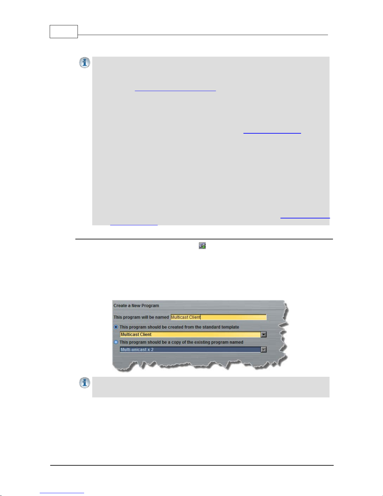
88 Bridge-IT M anua l
© Tieline Pty. Lt d. 2015
16.6
Configuring Multi cast Client Programs
Importa n t Notes: Before you commence program configuration please note:
· Ensure all connection related settings like the port, algorithm, bit rate (etc) match on
both multicast server and client programs or they will not connect successfully.
· You cannot edit a program when it is currently loaded in the codec.
· You can lock a loaded custom program in a codec to ensure the currently loaded
program cannot be unloaded by a codec dialing in with a different program type.
· Some drop-down menus and settings may be greyed out intentionally depending on
features available.
· It is possi ble to save a program at several points t hroughout t he program wizard and
use default sett i ngs t o save configuration time.
· T o learn more about programs see the section titled About Program Dialing.
· Always dial the multicast server codec connection first before connecting multicast
client codecs.
· Multicast client codecs will display return link quality (LQ) only. The Return reading
represents the audio being downloaded from the network locally. Multicast server
codecs do not display LQ readings.
· The default UDP audio port setting is 9000 and the client and server port settings must
match.
· Forward Error Correction (FEC) is not available for multicast connections.
· Use firmware higher than 2.8.xx in the Bridge-IT, Genie and Merlin families of codecs to
enable auxiliary data.
· It is not possible to connect to a G3 codec and receive multicast IP audio streams.
· To copy multicast client programs onto multiple codecs see Save and Restore
Configuration Files.
Configuring Multi cast Cli ent Programs
1. Open the web-GUI and click the Programs symbol at the top of the screen to display the
Programs panel.
2. Click the New Program button to open the wizard and:
· Click in the text box to name the new program.
· Select Multicast Client to configure a multicast program, or if you want to use an
existing program as a template, select this option. Then click Next.
Importa n t Notes: When you decide to use an existing program as a template, t he new
program inherits all t he set t ings of the template program and you can adjust t hese s ett ings
as required by continuing through the program wizard.
3. Enter a name for the Audio Stream, then click Next.
Page 89
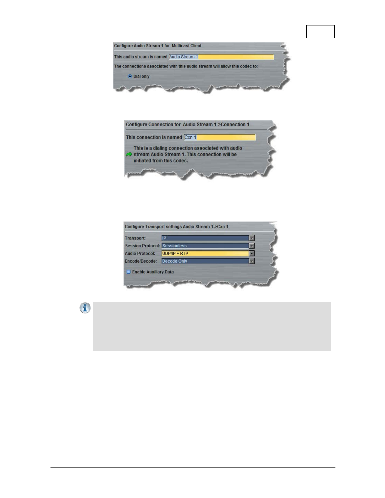
89
© Tieline Pty. Lt d. 2015
Bridge-IT M anua l
4. This audio stream connection in the wizard will allow the codec to dial. Enter the name of the
connection in the text box, then click Next.
5. Follow the instructions on the right-hand side of the panel to configure the transport settings for
the connection, then click Next. Note: select UDP/IP +RTP for RFC compliant streaming. If
auxiliary data is enabled the audio stream will not be RFC-compliant.
Importa n t Notes:
· T he encode and decode direction is configured automatically for Encode Onl y (server
prog ram) or De code Onl y (cli ent program). This setti ng is c onfigured when you select
either Multica st Server or Mul tica st Cli ent when you first create the program in the
wizard.
· Use firmware higher than 2.8.x x i n the Bridge-IT, Genie and Merlin families of codecs to
enable auxiliary data.
6. Configure the multicast IP address and audio port (the same multicast address and port must be
used for both the server and client programs), then specify which IP streaming interface is used to
dial this connection, e.g. Primary (LAN / ETHERNET port and default setting) or VLAN if
configured. Note: By default Any will select Primary.
Page 90
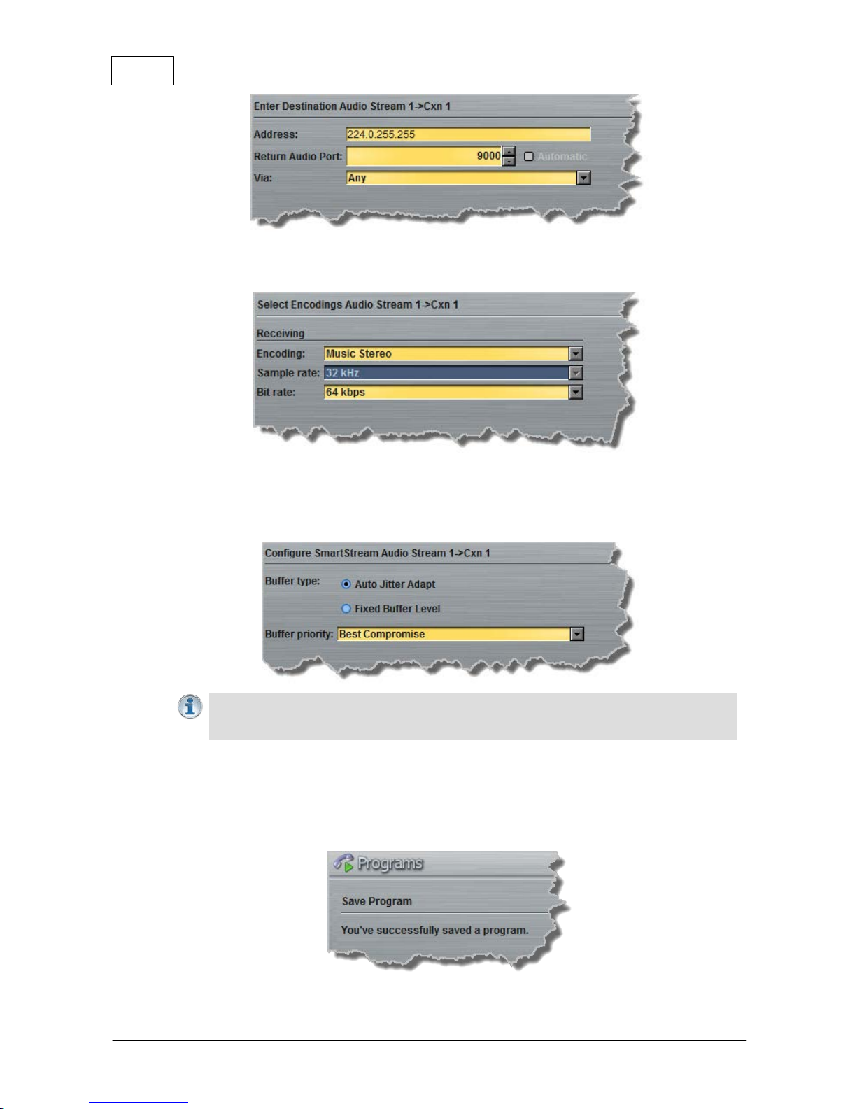
90 Bridge-IT M anua l
© Tieline Pty. Lt d. 2015
7. Click the drop-down arrows on the right-hand side of each text box to select the Encoding,
Sample rate, Bit rate or Sample size options. Click Next to continue.
8. Click to configure:
· Auto Jitter Adapt and the preferred auto jitter setting using the drop-down arrow for Buffer
Priority, or
· Fixed Buffer Level and enter the Jitter Depth (5000ms maximum).
Importa n t Notes: Automatic or fixed jitter buffer settings c an be adjusted on indivi dual
client c odecs as required. There is no jitt er buffer setting on the server codec because it
never receives audio packets .
9. Click to select Enable Auto Reconnect to enable automatic reconnection, then either:
i. Click Next to select Enable File Playback on silence detection, or
ii. Click Save Program to save the program at this point.
When you save the program it will be confirmed by the following message.
Page 91

91
© Tieline Pty. Lt d. 2015
Bridge-IT M anua l
10.Click Finish and the newly created program will be displayed in the left pane within the
Programs panel and in the Master panel.
11.Configure multicast server and multicast client programs and load all codecs with the appropriate
program. Select and connect audio streams in a program using the Master panel, or dial the
program manually using the codec front panel. Dial the multicast server program connection first
and then connect multicast client codec programs to begin receiving multicast audio packets.
16.7 Configuring SIP Settings
The codec is fully EBU N/ACIP Tech 3326 compliant when connecting using SIP (Session Initiation
Protocol) to other brands of IP codecs.
About SIP
SIP provides superior interoperability between different brands of codecs due to its standardized
protocols for connecting devices and is intended to be used when connecting Tieline codecs to nonTieline devices. Devices primarily use SIP to dial another device’s SIP address and find its location
with a minimum of fuss. This task is usually performed by SIP servers, which communicate between
SIP-compliant devices to set up a call.
When connecting two devices, SDP performs similar tasks to Tieline’s proprietary session data,
which is used to configure all non-SIP IP connections. There are two very distinct parts to a call
when dialing over IP. The initial stage is the call setup stage and this is what SIP is used for. The
second stage is when data transference occurs and this is left to the other protocols used by a
device (i.e. using UDP to send audio data).
All the mandatory EBU N/ACIP 3326 algorithms are supported (G.711, G.722, MPEG-1 Layer 2 and
16 bit PCM), as well as optional algorithms including LC- AAC, HE-AAC and aptX Enhanced. The
default algorithm selected when connecting using SIP is G.711.
Importa n t Notes:
· Each codec s hould be registered to a different SIP server account to avoid connection
conflicts.
· SIP dialing is only supported over peer-to-peer connect ions, not mult i -unicast
connections.
· Tieline G3 codecs do not support AAC and will default to MP E G Layer 2 if a Bridge-IT
codec configured for AAC attempts t o c onnect.
· Some Telcos and ISPs may bloc k S IP traffic over UDP port 5060.
· SIP account registration can only be configured via the Ethernet port and not a VLAN.
· When connecting to a Tieline G3 codec using SIP you need to manually selec t t he G3
audio reference level in the codec. To do this select SETTINGS > Audio > Re f
Level > Ti eli ne G3. In addition, select t he following on the G3 codec prior to dialing.
Select either a mono or stereo profile
Select [Menu] > [Configuration] > [IP1 Setup] > [Session Type] > [SIP]
Select [Menu] > [Configura tion] > [IP 1 S etup] > [Algorithm] > [G711/G722 or
MP2]
SIP Server Connections: Getting Started
Registering codecs for SIP connectivity is simple. First, choose the SIP server that you wish to
register your codec with. On a LAN this may be your own server, or it could be one of the many
internet servers available. We recommend that you use your own SIP server and configure it to use
G.711, G.722, MP2 and AAC algorithms. This is because most internet SIP servers are for VoIP
Page 92
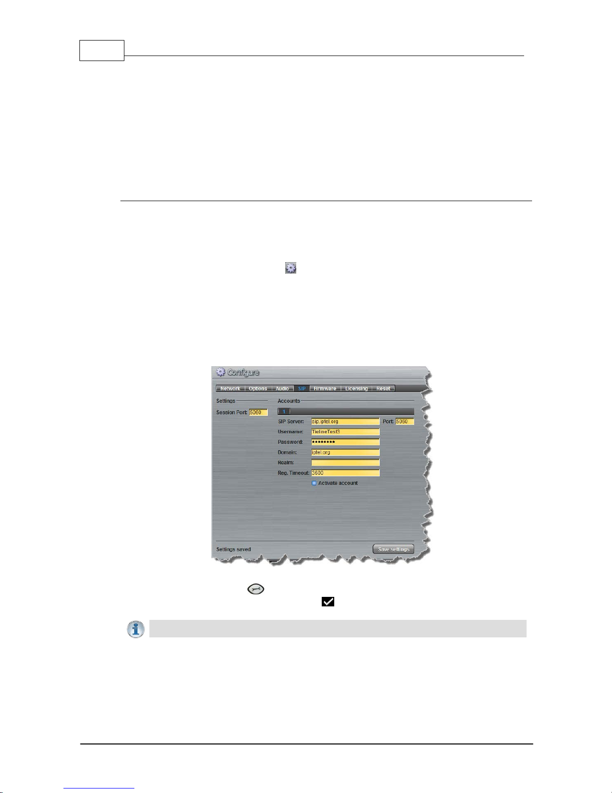
92 Bridge-IT M anua l
© Tieline Pty. Lt d. 2015
phones and are only configured for G.711 and GSM algorithms.
When you register an account with a SIP server you will be provided with:
· The SIP server IP address.
· A username (often the same as a SIP number).
· A password.
· Domain details.
· Realm details (sometimes).
Configure the Codec for SIP using the Web-GUI
Use the Toolbox web-GUI to program SIP account registration details into your codec. Once these
details have been entered into the codec, each time it is connected to a public IP address it will
contact the SIP server automatically to acknowledge its presence over a wide area network.
1. Connect your codec to a LAN connection with a public IP address, then login to the Toolbox
web-GUI and click the Settings symbol at the top of the screen to display the Settings
panel.
2. Click the SIP button.
3. Enter the account details into the relevant text boxes.
4. Enter the Registration Timeout (this shouldn't need to be adjusted from the default setting).
5. Click to select Activate Account and click the Save Settings button to create the account
in the codec. Settings Saved is displayed in the bottom-left corner of the Settings panel if
the account details are saved successfully.
5. Navigate to SETTINGS > SIP > Accounts to verify that the account has been registered
to the SIP server. The registration symbol appears when it is activated successfully.
Importa n t Notes: Some ISPs may block SIP traffic over UDP port 5060.
Page 93
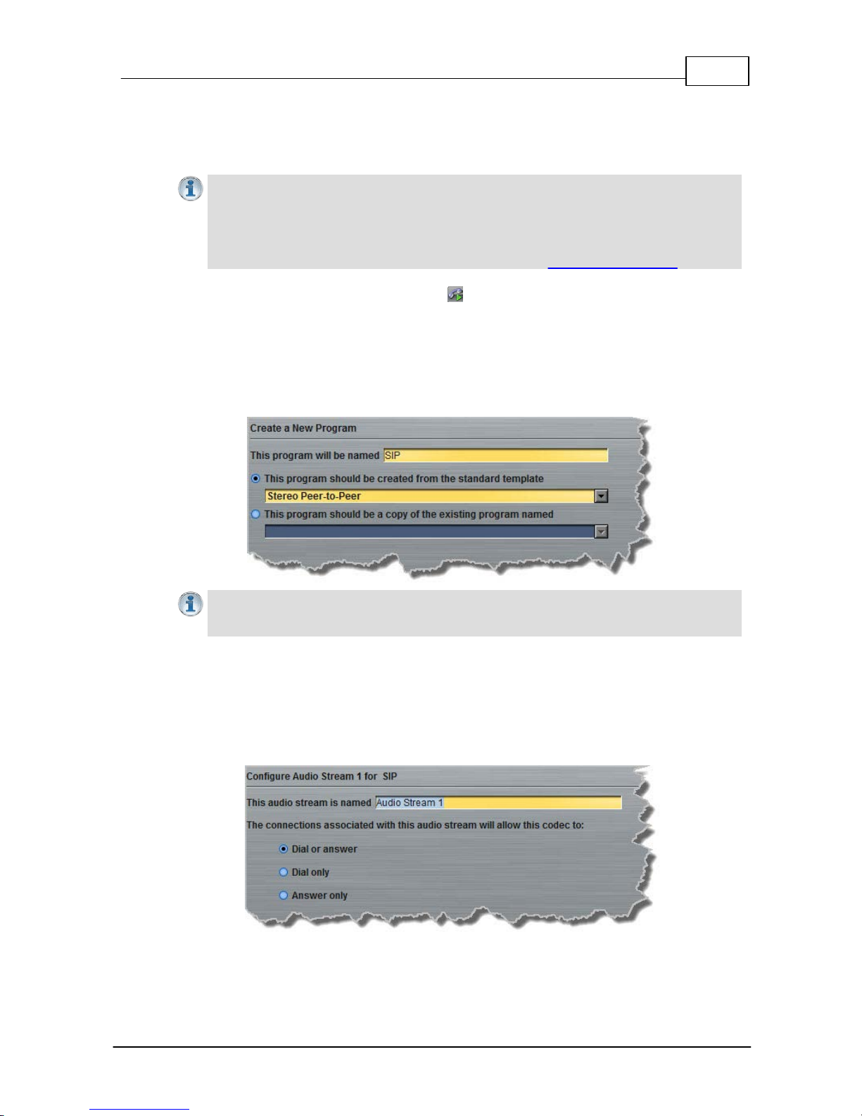
93
© Tieline Pty. Lt d. 2015
Bridge-IT M anua l
16.8
Configuring SIP Programs
SIP programs are like a normal IP program to configure, with two small differences; entering a SIP
address and selecting SIP as the Session Protocol.
Importa n t Notes: Before you st art program configuration please note:
· SIP can only operate using the LAN / ETHERNET port on the rear panel of the codec.
· You cannot edit a program when it is currently loaded in the codec.
· Some drop-down menus and settings may be greyed out intentionally depending on
features available.
· T o learn more about programs see the section titled About Program Dialing.
1. Open the web-GUI and click the Programs symbol at the top of the screen to display the
Programs panel.
2. Click the New Program button to open the wizard and:
· Click in the Program Name text box to name the new program.
· Select Mono/Stereo Peer to Peer, or if you want to use an existing program as a template,
select this option. Then click Next.
Importa n t Notes: When you choose to use an exist ing program as a template, t he new
program inherits all t he set t ings of the template program and you can adjust t hese s ett ings
as required by continuing through the program wizard.
3. Enter a name for the Audio Stream and configure the codec to dial, answer or dial and
answer. Then click Next.
Note: The following example will display how to configure a dial and answer program. If you want the
codec to either dial or answer only, select the option and the wizard will automatically display
screens to allow you to configure the codec correctly.
4. This audio stream connection in the wizard will allow the codec to dial. Enter the name of the
connection in the text box, then click Next.
Page 94
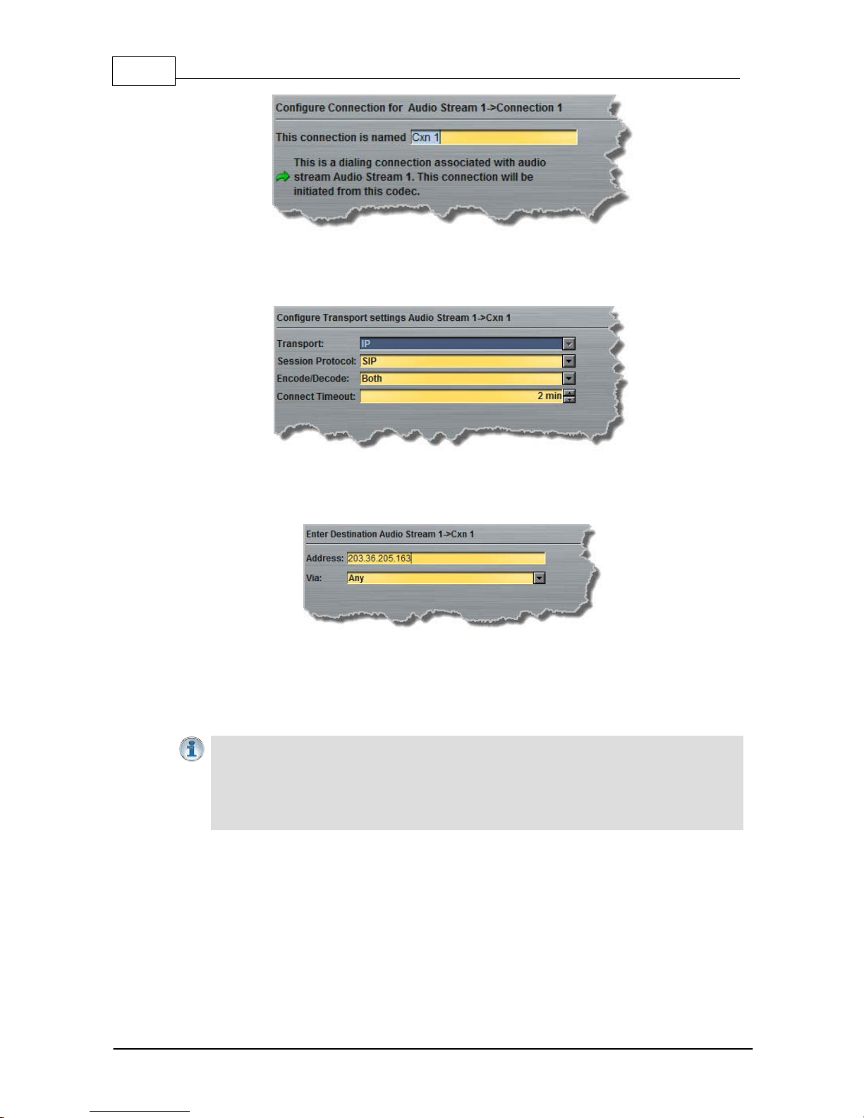
94 Bridge-IT M anua l
© Tieline Pty. Lt d. 2015
5. Follow the instructions on the right-hand side of the panel to configure the transport settings
for the connection: Ensure that you select SIP as the Session Protocol menu. Then click
Next.
6. Configure the destination codec Address and Audio Port, then the network interface used to
dial the connection, e.g. Primary (LAN / ETHERNET port and default setting) or VLAN if
configured. Note: By default Any will select Primary.
At this point you can click Save Program and save the program with the default jitter and FEC
settings in the codec. Alternatively, click Next to specify individual algorithm, jitter buffer and
FEC settings for this connection and configure backup audio for this audio stream
(recommended).
Importa n t Notes:
· If your codec is registered with same SIP registrar as t he destination codec t hen you
only need to enter the SIP user name to dial suc c es s fully.
· The default UDP audio port when using S IP is 5004 in Tieline codecs. To contact a codec
that is behind a firewall or NAT-enabled router, it is essential that this and all other
relevant ports are open and forwarded to the other device.
7. Click the drop-down arrows on the right-hand side of each active drop-down menu to adjust
the Encoding, Sample rate or Bit rate parameters. Click Next to continue.
Page 95
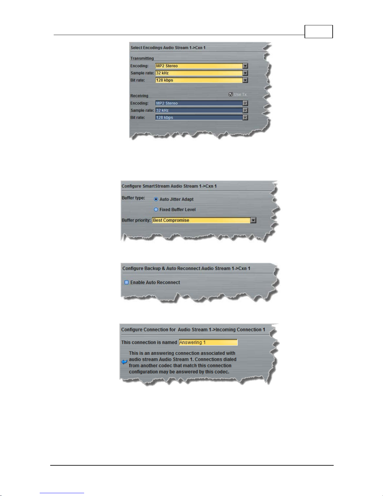
95
© Tieline Pty. Lt d. 2015
Bridge-IT M anua l
8. Click to configure:
· Auto Jitter Adapt and the preferred auto jitter setting using the drop-down arrow for Buffer
Priority, or
· Fixed Buffer Level and enter the Jitter Depth (5000ms maximum).
9. Click to select Enable Auto Reconnect to enable automatic reconnection, then click Next.
10.Enter a name for the answering connection and click Next.
11.Follow the instructions on the right-hand side of the panel to configure the Transport,
Session Protocol and Audio Port (preconfigured for SIP) settings for the connection, then
click Next.
Page 96
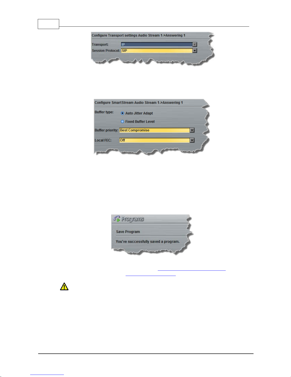
96 Bridge-IT M anua l
© Tieline Pty. Lt d. 2015
12.Click to configure jitter buffer and FEC settings:
· Auto Jitter Adapt and the preferred auto jitter setting using the drop-down arrow for Buffer
priority, or
· Fixed Buffer Level and enter the Jitter Depth (5000ms maximum).
13.After configuring these settings there are 3 options:
i. If you want to create another answering connection, select the check-box for Create
another answering connection at the bottom of the panel and continue through the
wizard.
ii. Click Next and select Enable File Playback on silence detection.
iii.Click Save Program to save the program at this point.
When you save the program it will be confirmed by the following message.
5. Click Finish and the newly created program will be displayed in the left pane within the
Programs panel and in the Master panel. Select and connect audio streams in a program
using the Master panel, or dial the program manually using the codec front panel.
Caution: If the codec LAN cable is dis c onnected and the IP address changes when dialing
in SIP mode, you will need to reboot t he codec, ot herwise the codec will not be able to
reconnect.
Page 97
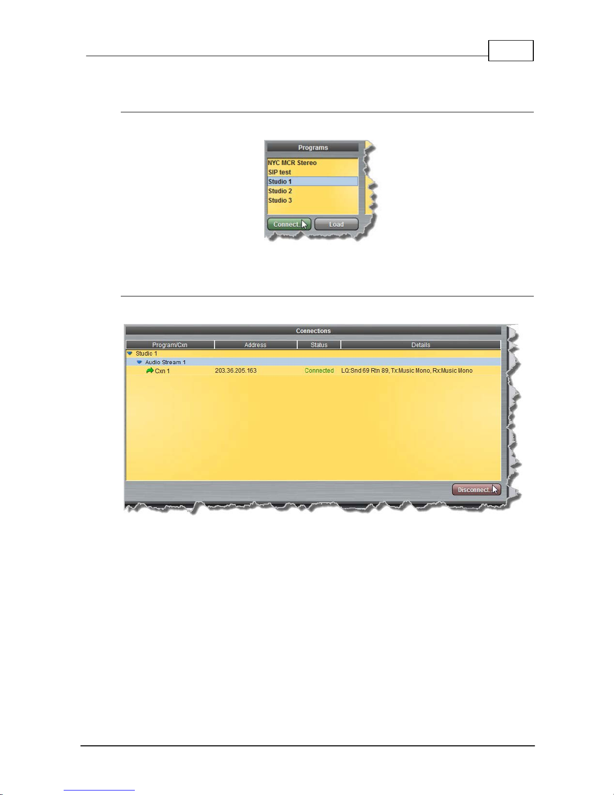
97
© Tieline Pty. Lt d. 2015
Bridge-IT M anua l
16.9
Dial and Disconnect a Program
Connecting a Program
1. Click to select the program you want to load from the Programs list in the Master panel.
2. Click Connect to load the program and connect all audio streams.
Disconnecti ng a Program
1. Click to highlight the audio stream in the Connections pane of the Master panel.
2. Click Disconnect to end the connection.
Page 98
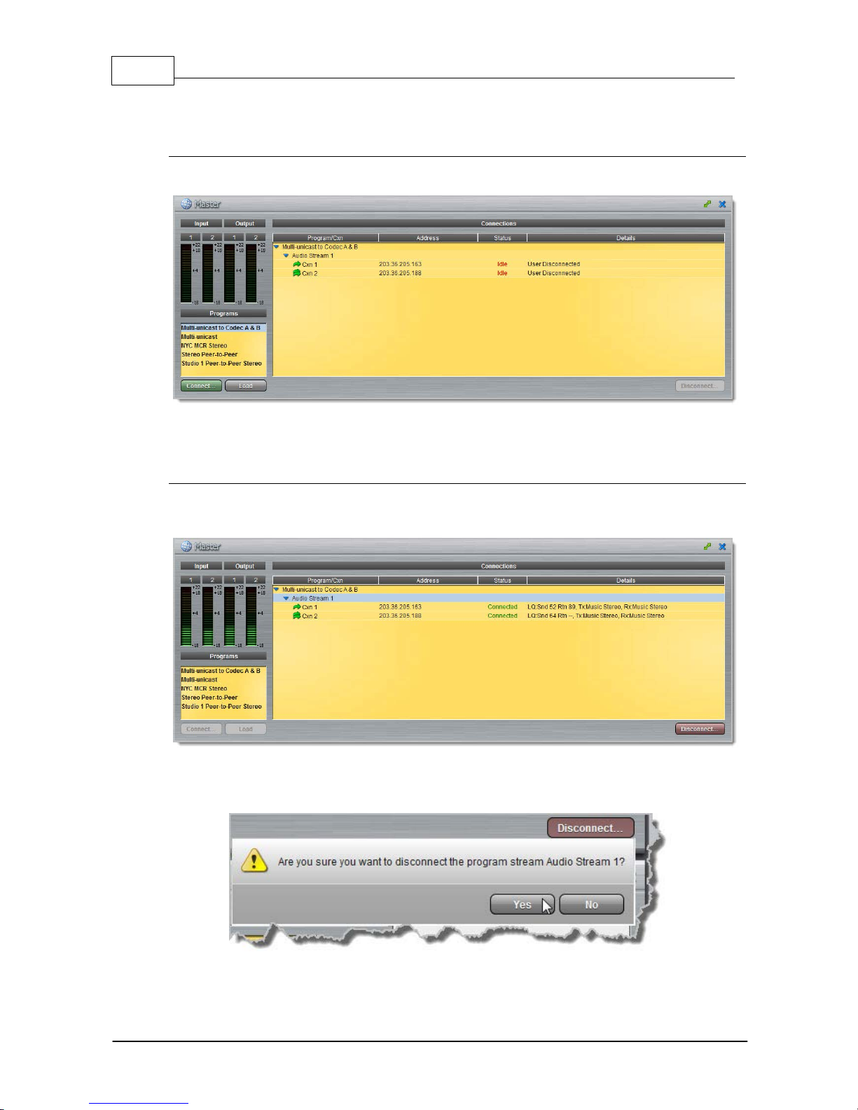
98 Bridge-IT M anua l
© Tieline Pty. Lt d. 2015
16.10
Dial and Disconnect Multi- unicast Connections
Dial Mult i pl e Connections wit hin a Program
1. Click to select the program you want to load from the Programs list.
2. Click Connect to load the program and connect all connections.
Disconnect A l l A udio Stream Connections
1. Click to select the program in the Connections pane, e.g. Multi-unicast to Codec A & B in the
following example.
2. Click the Disconnect button.
3. Click Yes in the confirmation dialog to disconnect all audio stream connections.
Page 99
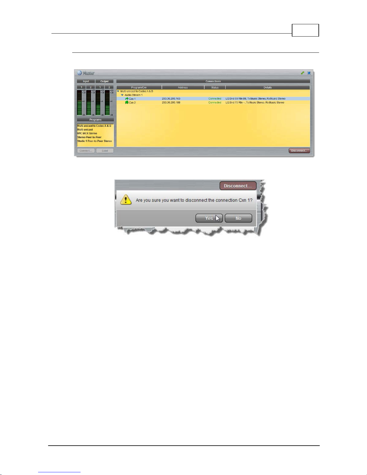
99
© Tieline Pty. Lt d. 2015
Bridge-IT M anua l
Disconnect a Single A udio Stream Connection
1. Click to select the audio stream connection you want to disconnect.
2. Click the Disconnect button.
3. Click Yes in the confirmation dialog to disconnect all audio stream connections.
Page 100
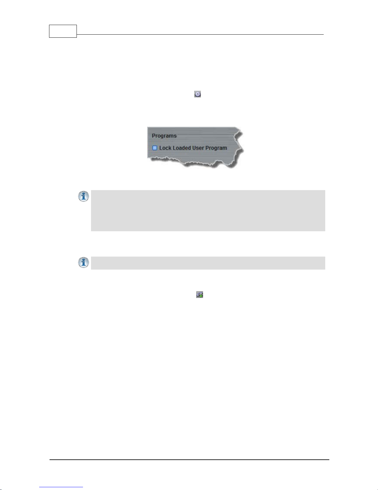
100 Bridge-IT Manua l
© Tieline Pty. Lt d. 2015
16.11
Lock or Unlock Programs
It is possi ble to lock a loaded custom program in a codec to ensure the currently l oaded program
type, e. g. mono, c annot be unloaded by a codec dialing in with a different program ty pe, e.g. stereo.
For example, if you require the codec at t he st udio to always c onnect in mono, sim ply load and lock
a mono program in the codec.
1. Open the web-GUI and click the Settings symbol at the top of the screen to display the
Settings panel.
2. Click the Options button at the top of the Settings panel.
3. Click the Lock Loaded User Program check-box to lock or unlock a user program in the codec.
4. Click Save Settings at the bottom of the panel to save the new configuration.
Importa n t Note:
· It is only possible to lock custom programs in a codec.
· If Lock Progra m i s enabled and you load a new custom program in the codec, Lock
Program remains enabled and locks t he most recently loaded cus t om program.
· A red Padlock symbol appear s in the Status section of the Ma ster pan el to indicat e a
program is lock ed in the codec.
16.12 View/Edit/Delete Programs
Importa n t Notes: You cannot edit or delete a program when it is c urrently loaded in the
codec. E nsure you have unloaded a program prior to editing the current configuration.
To vi ew configuration setti ngs for an exis t ing program, or edit sett ings:
1. Open the web-GUI and click the Programs symbol at the top of the screen to display the
Programs panel.
2. Click to select a program in the left-hand pane.
 Loading...