

Page 1
Frost Free
Foundation System
Installation Instructions
Updated:
03/15/12
By Tie Down Engineering
Heavy Duty
Part #59373
Standard
Part #59372
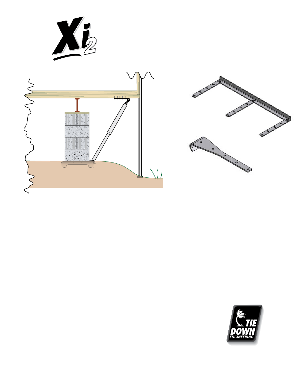
A cost effective Engineered Perimeter Foundation Support for use with Frost Protected designs meeting Model
Installation “Standard”, HUD 24 CFR 3285, International Residential Code (IRC) Appendix E and ANSI A225.1.
Based on design assumptions from the “Standard” for frame plus perimeter pier support:
Max 16’nominal sections width (15’ actual), 12” eave, 300 lb. pier dead load, 35 plf wall dead load, and
10 plf chassis dead load.
Two separate joist support options, depending on needed load (see chart on page 4), allow for replacement of
perimeter piers up to a maximum of 8 ft. for a 40 lb. roof live load. Table 2, 3285.303 perimeter blocking, this
does not include flood and seismic design loads.
Follow the Manufacturers Installations Instructions in conjunction with the “Standards” for site contour and
drainage. This design follows the guidelines for proper site preparation that doesn’t allow moisture under the
home, and without moisture there is no frost heave.
The Xi2 Frost Free Foundation can be installed on concrete footers or steel
ground pans at all required locations. Tie Down ABS footer pads or concrete
footers can be used at all other pier locations with stacked concrete or steel
piers. Follow manufacturers set up Manual, local or state requirements for
proper footer spacing and all other set up requirements.
www.tiedown.com
Instruction #08156
Page 1
031512,D1165
Page 2
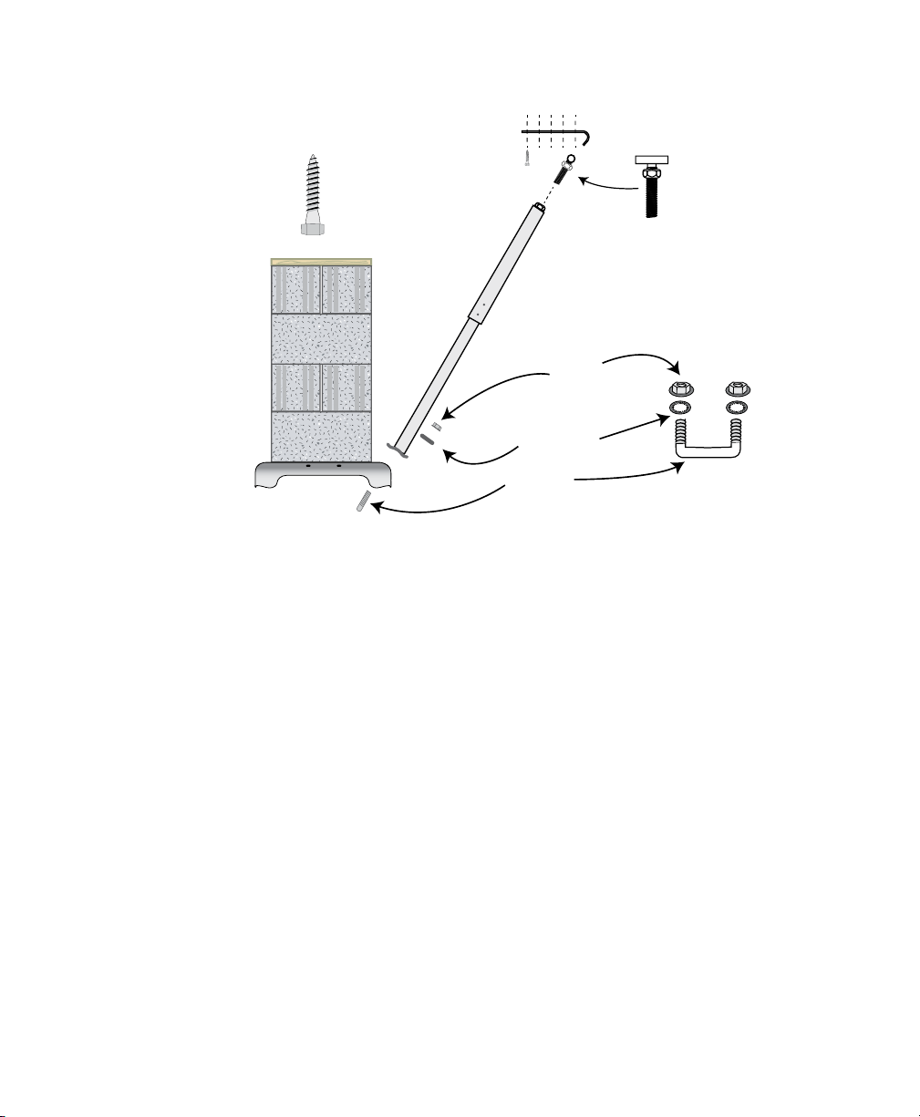
Frost Protection Strut - Ground Installation
Joist Bracket
with Lag Bolts
T-bolt
Compression
Strut
Nut
Xi2
Foundation
Pa d
Ground Installation
1. Check the manufacturers set up manual to identify the amount of perimeter blocking required for pier
spacing and roof load. We offer 2 different Joist brackets for use based on amount of load needed.
2. Systems are installed in conjunction with complete Xi2 systems or at separate specified perimeter
support locations.
3. Make sure all organic matter and debris are cleared from pad site.
4. Place U-bolt through pan facing to outside of home and attach lock washers.
5. Press or drive pan into the ground until level and flush with ground surface.
6. Build pier according to State, local, or home manufacturers guidelines.
7. Attach to floor joists approximately 6” in from outside wall using 3/8” X 3” lag bolts in
pre drilled holes in Joist Bracket. Keep strut angle as close to 45 degrees as possible.
8. Install compression strut by placing mount bracket over U-bolt and attach with nuts.
Do not tighten at this time.
9. Insert adjustable T-bar head in top of compression strut with nut screwed to top of the rod
next to T. Slide the T end of strut up and position to rest in the bend of angle iron support.
While holding in place, install a minimum of 4 (#14 X 1” tek screws) self tapping screws into
the holes provided in the compression strut so the two tubes are connected together with a
minimum overlap of 4” to 6”.
10. Tighten nuts on U-bolt at ground pan.
11. Adjust support by tightening T-bar against Joist Bracket support with adjustment nut.
Washer
U-bolt
Page 2
Page 3

Frost Protection Strut - Concrete Installation
Joist Bracket
T-bolt
with Lag Bolts
Compression
Strut
Minimum Distance
From Edge: 2-1/2”
Concrete Installation
1. Check manufacturers set up manual to identify the amount of perimeter blocking required for pier
spacing and roof load. We offer 2 different Joist brackets for use based on amount of load needed.
2. Systems are installed in conjunction with complete Xi2 systems or at separate specified perimeter
support locations.
3. Using poured concrete pad locations under piers, drill two 3/8” X 3” deep holes in concrete using the
galvanized bracket as a guide. Attach bracket to concrete using 3/8” X 3-1/2” wedge anchors provided.
Place nut and washer on anchor; leave enough room for 1 to 2 threads showing on top of bolt. Using a
hammer, tap the wedge bolts into hole through bracket, leaving nut & washer flush with bracket.
Tighten wedge bolt securing bracket to concrete.
4. Build pier according to State, local, or home manufacturers guidelines.
5. Attach Joist Bracket support to floor joists approximately 6” from outside wall using 3/8” X 3” lag bolts in
pre-drilled holes in the Joist Bracket. Keep strut angle as close to 45 degrees as possible.
6. Attach compression strut to concrete bracket with 1/2” bolt provided. Do not tighten at this time.
7. Insert adjustable T-bar head in top of compression strut with nut screwed to top of the rod next to T.
Slide T end of strut up and position to rest in the bend of angle iron support. While holding in place, install a
minimum of 4 (#14 X 1” tek screws) self tapping screws into holes provided in the compression strut so the
two tubes are connected together with a minimum over lap of 4” to 6”.
8. Tighten nuts on strut to concrete bracket at this time.
9. Adjust support by tightening T-bar against the Joist Bracket support with adjustment nut.
Page 3
Page 4

Minimum Number of Lag Screws Required
Strut
Roof Live Load / Flat Roof Snow Load (PSF)
Spacing
20 25 30 35 40 45 50 55 60
4’ - 0” 5 6 6 7 7 8 8 9 9
5’ - 4” 7 8 8 9 9 10 11 11 12
6’ - 8” 8 9 10 11 12 13 13 14 15
8’ - 0” 10 11 12 13 14 15 N/A N/A N/A
Heavy Duty System
Page 4
Manufactured Housing Products Division TIE DOWN ENGINEERING
255 Villanova Drive S.W. • Atlanta Georgia 30336
(800) 241-1806 • (404) 344-0000 • Fax (404) 349-0401
Trade, Brand, and Product Names are the Property of
TIE DOWN ENGINEERING, ©2012 TIEDOWN, Inc.
Part #59373
 Loading...