

Page 1
Steel Pier System
Installation Instructions for Wind Zone I, II & III
By Tie Down Engineering
Updated: 8/9/06
• Easy installation
• 3 Sq ft pad & pier replace standard support pier and base
• Arms of pier easily handle longitudinal stabilization requirements
• Heavy galvanized coating* on bracket and struts
• Screw type peir adjusters... No need to use installation jacks to adjust home to system
REQUIREMENTS
• Install in any type of soil, 4B(175-275 lbs.) or better.
• Maximum vertical projection at sidewall is 9’. Higher walls may be used when the design loads are
adjusted accordingly.
• Main rail spacing must be 75.5” - 99.5”
• Wind Zone II & III generally require sidewall anchors. Check manufacturers requirements.
• Additional vertical anchor ties that are unique to a home's design may be required by the home
manufacturer. These locations may include shear walls, marriage line ridge beam support posts, and rim
plates. The longitudinal component of the Xi2 system replaces end frame ties. Check manufacturers
set-up requirements.
• Maximum pier height is 48” pier.
• Systems must be placed as evenly as possible, no more than 10’ from end of home.
• Additional systems may be needed for roof slopes greater than 20 degrees, (4.37” in 12” Pitch ) See Page 4.
• Two systems designed to work in conjunction with each other.
* Xi2 components exceed HUD code 3280.307g "Anchoring equipment exposed to weathering shall have a
resistance to weather deterioration at least equivalent to that provided by a coating of zinc on steel of not
less than 0.30 ounces per square foot of surface coating...."
080906,D848
Page 2
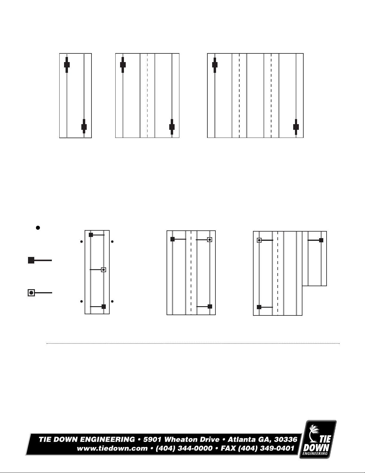
Xi2 Longitudinal Pier Placement
Single Section
Up to 16’ Nominal
Double Section
Up to 32’ Nominal
Triple Section
up to 48’ Nominal
When pier with LSD struts is used only as longitudinal stabilization, systems must be as evenly spaced as
possible, no more than 10’ from the end of the home.
Xi2 Lateral Stabilization Pier Placement
30”
Anchor*
Xi2 Pier
Placement
3rd System
for Placement
Single Section Home - WZ I & II
0 - 76’ Box 2 Xi2 Systems
Over 76’ Box 3 Xi2 Systems
Single Section Home - WZ III
0 - 64’ Box 2 Xi2 Systems
Over 64’ Box
* For Wind Zone I - 30” anchor w/vertical strap or frame tie w/stabilizer plate, within 10’ of end of home on single sections.
NOTE: Diagram represents single section up to 16’ width, double section up to 32’ width,
and triple section homes up to 48’ width.
3 Xi2 Systems
Double Section Home - WZ I & II
0 - 76’ Box 2 Xi2 Systems
Over 76’ Box 3 Xi2 Systems
Double Section Home - WZ III
0 - 64’ Box
Over 64’ Box
2 Xi2 Systems
3 Xi2 Systems
Triple Section Home - WZ I & II
0 - 76’ Box 2 Xi2 Systems
Over 76’ Box 3 Xi2 Systems
riple Section Home - WZ III
T
0 - 64’ Box
Over 64’ Box 3 Xi2 Systems
2 Xi2 Systems
080906,D848
Page 3

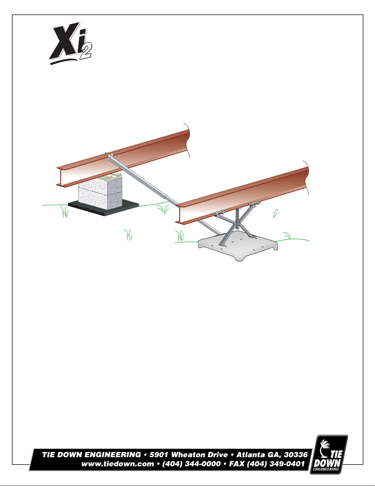
Installation of Longitudinal System (Figure 1)
4 - #12 X 1”
Tek Screws
(2 per side)
Beam Clamp
Bracket
J-Bolt
1-1/2" Tube
Lateral Struts
1-3/4" Tube
Longitudinal
Struts
Bolt
Pier Base
Pier Base
Extension
Post
Height
Adjuster 0-3"
Frame
Bracket
Strut
Foundation
Base Pa d
All Components Hot Galvanized Coated
1. Identify the number of systems to be used on the home using the chart provided.
2. Identify on the location where the longitudinal systems will be installed.
3. Clear all organic matter and debris from the pad site.
4. Place pad centered under beam using the centering mark imprinted on the pad.
5. Press or drive pan into ground until level and flush with prepared surface.
6. Slide Xi-System pier feet into slots in pad so that the Xi-system pier is centered under the I-beam.
7. Raise telescoping extension post to contact the bottom of I-beam, secure with bolt provided, tighten
bolt nut.
8. Turn hex nut on pier height adjuster until Xi-System pier is rigid between pad and I-beam.
9. Install Gator Beam clamps to I-beam on each side of the Xi-System pier. Do not tighten nuts at
this time.
10. Connect struts (open side down) to each side of the Xi-System pier using the U- bolt provided. Struts are
attached to the upper hole in each pier leg and to the flanges on the beam clamps. (Figure 1)
11. Tighten all nuts and bolts on the struts and beam clamps.
(Figure 1)
(Figure 2)
Installation of Lateral System (Figure 3)
1. Assemble lateral strut by sliding smaller (1-1/2”) tube into the larger (1-3/4”) tube. Holes should be on the
sides of the larger tube and the “flag” up on the larger tube.
2. Attach the end of the smaller tube to the inside of the pan using u-bolts and nuts provided.
3. Attach the flag end of the larger tube to the opposite I-beam using the “J” bolt over the top of the I-beam
with the nut & washer provided.
4. Install a minimum of four(1/4”x3/4’) self-tapping screws into the holes provided in the lateral strut so that the two
tubes are connected together.
(Figure 4)
(Figure 1)
(Figure 1)
igure 4)
(F
(Figure 2)
(Figure 3)
080906,D848
Page 4

Lateral Strut
J-Bolt
Beam Clamp
Bracket
Longitudinal Strut
Foundation
Base Pa d
Wind Zone I Wind Zone II Wind Zone III
5:12 6:12 7:12 9:12 5:12 6:12 7:12 9:12 5:12 6:12 7:12 9:12
34 22 2 2 2 2 2 2 2 2 3 3
36 22 2 2 2 2 2 3 2 2 3 3
38 22 2 3 2 2 2 3 2 3 3 3
40 22 2 3 2 2 2 3 3 3 3 3
42 22 3 3 2 2 3 3 3 3 3 3
44 22 3 3 2 2 3 3 3 3 3 3
46 23 3 3 2 3 3 3 3 3 3 4
48 23 3 3 3 3 3 3 3 3 3 4
50 33 3 3 3 3 3 3 3 3 3 4
52 33 3 3 3 3 3 3 3 3 4 4
54 33 3 3 3 3 3 3 3 3 4 4
56 33 3 3 3 3 3 3 3 3 4 4
58 33 3 3 3 3 3 3 3 3 4 4
60 33 3 3 3 3 3 3 3 3 4 5
62 33 3 3 3 3 3 3 4 4 4 5
64 33 4 4 33 4 4 4 4 4 5
66 33 4 4 33 4 4 4 4 4 5
68 34 4 4 34 4 4 4 4 5 5
70 34 4 4 34 4 4 4 4 5 5
72 34 4 4 4 4 4 5 4 4 5 5
74 4 4 4 5 4 4 4 5 4 5 5 5
76 4 4 4 5 4 4 4 5 4 5 5 6
78 4 4 4 5 4 4 4 5 4 5 5 6
80 4 4 4 5 4 4 4 5 4 5 5 6
Module
Length
(Feet)
Xi2 System Requirements for Roof Pitches Higher than 20 degrees
Steel Pier Systems P/N’s
#59321 Xi, 12” Pier
#59314 Xi, 25.5” Pier
#59317 Xi, 36” Pier
#59315 Xi, 5’ Lateral Strut
#59318 Xi, 6’ Lateral Strut
Block Pier Systems P/N’s
#59319 Xi, Lateral w/5’ Strut
#59320 Xi, Lateral w/6’ Strut
080906,D848
 Loading...