

Page 1
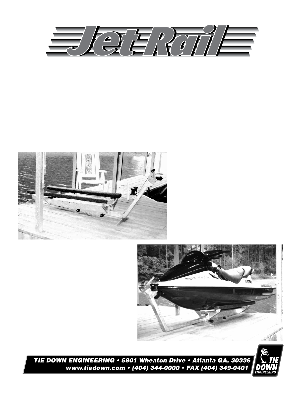
Owner's Manual
Parts list
Instruction guide
Warnings
Please read carefully before assembling and using product.
Tools required for assembly
Hammer
9/16" Wrench
3/4" Wrench
Ratchet
9/16" Socket
3/4" Socket
3/8" Socket
Phillips Screwdriver
Instructions #15377
071410,173
Page 2
Part # Stock # Description Qty.
1 26605 Jet Rail Frame Tube (72" long, 3x4) 1
2 26606 Jet Rail Carriage (20" long) 1
3 26607 Jet Rail Rear Deck Mount 1
4 26608 Jet Rail Front Deck Mount 1
5 26609 Jet Rail Deck (47" long) 1
6 26610 Winch Mount Extension Tube (42" long, 2x3) 1
7 26611 Winch Mount 1
8 26612 Bow Stop 1
9 26613 Winch Mount Tube 1
10 44816 Carpeted Bunk, 5' 2
11 17057 Keel Pad 6" Long 2
12 MWS15L Winch Strap, 15' 1
13 17150 Brake Winch, 800 lb. 1
HARDWARE
14 45245 Bushing, 4" 6
15 45246 Bushing, 1" 2
16 45251 Winch Strap Roller 1
17 44610 1/2" x 5-1/2" Rod 4
18 86116 Swivel Bracket 4
19 17085 2" End Cap 4
20 BPINLOCK Safety Locking Pin 1
21 BBPELLNUT500 1/2" Palnut 10
22 10602 Hair Cotter Pin 1
23 17052 Spool Roller 4" 2
24 10904 Self-Tapping Screw, #10 x 3/4" 4
25 10903 Self-Tapping Screw, #14 x 1-1/2" 8
26 10985 1/2" U-Bolt 2
27 BBB3750100 3/8" x 1" Hex Head Bolt 9
28 BBB3750400 3/8" x 4" Hex Head Bolt 6
Note: Two of the 3/8" x 4" hex head bolts are grade 5 bolts, used on page 4, section 5.
29 BBB3750300 3/8" x 3" Winch Bolt 1
30 10938 1/2" x 5-1/2" Hex Head Bolt 2
31 10936 1/2" x 7" Hex Head Bolt 1
32 10937 1/2" x 8-1/2" Hex Head Bolt 2
33 10645 1/2" Nyloc Nut 9
34 BBN375NL 3/8" Nyloc Nut 20
35 10504 1/2" Nylon Flat Washer 24
36 B58-15208 Nylon Bushing 12
37 BBW500 1/2" Washers 4
38 44540 Shackle Plate 1
TIE DOWN ENGINEERING • 5901 Wheaton Drive • Atlanta, GA 30336 • 404-344-0000
2
Page 3
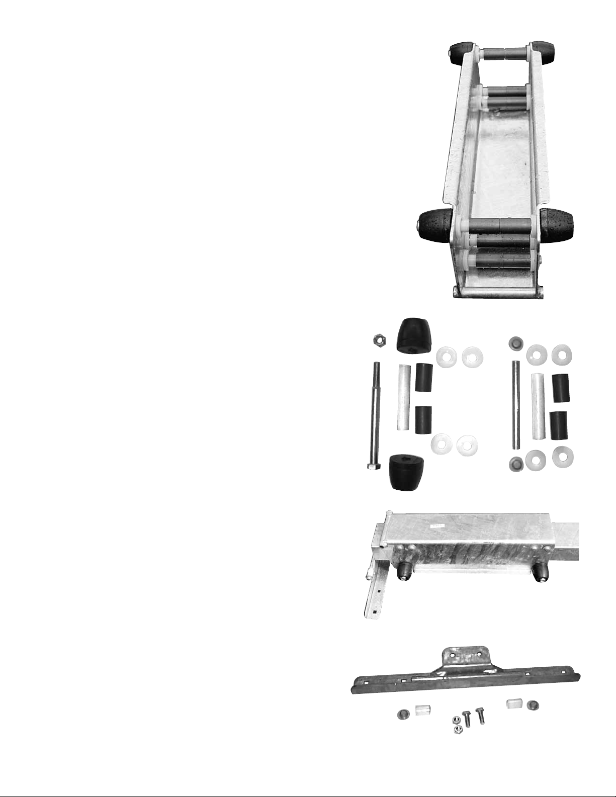
1. Assembly of Carriage
Step One
Roller assemblies are installed in the top four holes of the Jet Rail Carriage.
Hammer a palnut on one end of each of the four rods. Lay carriage upside
down as shown in picture 1. In "bottom" four holes, slide the rods through
one side of the carriage. Install 2 - 1/2" nylon washers, the 4" nylon bushing, 2 - short nylon bushings over the 4" bushing, 2 nylon washers, through
the other side of the carriage, hammer palnut on end of rod. Repeat for the
remaining three rods. (Picture 2 shows bushing/washer line up)
Parts required for this step.
# Stk. # Description Qty.
2 26606 Jet Rail Carriage 1
17 44610 1/2" x 5-1/2" Rod 4
21 BBBPELNUT500 Palnut 8
36 B58-15208 Nylon Bushing 8
14 45245 Bushing, 4" 4
35 10504 1/2" Nylon Flat Washer 16
Step Two
Install roller assemblies in two "upper" holes as shown in
Picture 1. Use 8" bolt as shown in picture 2 to assemble the roller
assemblies. Picture 1 shows nished assembly.
33
Parts required for this step.
# Stk. # Description Qty.
36 B58-15208 Nylon Bushing 4
14 45245 Bushing, 4" 2
35 10504 1/2" Nylon Flat Washer 8
19 17085 2" End Cap 4
32 10937
33 10645 1/2" Nyloc Nut 2
1/2" x 8-1/2" Hex Head Bolt 2
32
Picture 1
19
35
14
36
2. Attach Carriage to Frame Tube
Place carriage onto 72" frame tube, so that the swivel tube on
carriage points to the rear. Rear of frame tube has two holes
together on bottom to attach rear deck mount as shown in
Picture 3. (Front of tube has a single hole on each side of the
tube as shown in Picture 6)
3. Assemble & Attach Rear Deck Mount
Slide 1" bushings over rods on rear deck mount (Picture 4).
Secure with 1/2" palnuts. Use a hammer to attach palnuts to
rods. Using the two 3/8" x 1" hex head bolts and nyloc nuts,
attach the rear deck mount to the Jet Rail Frame Tube as
shown in Picture 3.
Parts required for this step.
# Stk. # Description Qty.
3 26607 Rear Deck Mount 1
1 26605 Frame Tube 1
15 45246 1" Bushings 2
21
27 BBB3750100 3/8"x1" Hex Head Bolts 2
34 BBN375NL 3/8" Nyloc Nuts 2
BBPELNUT500 1/2" Palnuts 2
3
21
19
Picture 3
15
27
Picture 4
Picture 2
3
15
21
34
Page 4

4. Attach Front Deck Mount to Frame Tube
Attach front deck mount to front of frame tube (front of tube
has a single hole on each side of the tube,Picture 6). Front deck
mount is mounted ush against end of the frame tube using the
U-bolt, metal washers and nyloc nuts as shown in Picture 5.
Parts required for this step.
# Stk. # Description Qty.
4 26608 Front Deck Mount 1
1 26605 Jet Rail Frame Tube 1
26 10985 1/2" U-Bolt 1
33 10645 1/2" Nyloc Nut 2
37 BBW500 1/2" Flat Washers 2
NOTE: At this time, place frame tube/carriage with deck
mounts attached, in the general area where you are planning to attach the Jet Rail to your dock. Make sure there
is room for the watercraft to be winched onto the Jet Rail
without obstructions.
9
26
Picture 5
37
1
33
4
4
Picture 6
1
6
5. Attach Winch Mount Extension Tube
to Winch Mount Tube.
Slide Extension Tube into front of Jet Rail Frame Tube. Cut-out
in front deck mount matches the end that slides into the tube.
Bolt winch mount tube to extension tube using the 2- 3/8" x 4"
Grade 5 hex head bolts and nyloc nuts (Picture 7).
Parts required for this step.
# Stk. # Description Qty.
1 26605 Jet Rail Frame Tube 1
6 26610 Winch Mount Ext. Tube 1
9 26613 Winch MountTube 1
28 BBB3750400 3/8" x 4" Hex Head Bolts 2
34 BBN375NL 3/8" Nyloc Nut 2
6. Attach Jet Rail Deck To Carriage Assembly
Lift Jet Rail deck assembly over carriage. Align carriage tube
hole with pivot hole in deck. (Picture 8) Install 1/2" x 7" bolt with
1/2" nyloc nut. (Front of deck has two holes on each side)
Parts required for this step.
# Stk. # Description Qty.
5 26609 Jet Rail Deck Assembly 1
2 26606 Jet Rail Carriage Assembly 1
31 10936 1/2" x 7 " Hex Bolt 1
33 10645 1/2" Nyloc Nut 1
9
6
1
Picture 7
Markings on Grade
5 Hex Head Bolt
A locking pin is provided to hold winch
extension tube in place, using side holes
in frame tube and holes in estension tube
(above).
Picture 8
4
5
31
‘
Front
4
Page 5

7. Attach Bunks to Jet Rail Deck
Attach one swivel bracket on each "corner" of the Jet Rail
Deck as shown in Picture 9. There are several holes in which to
adjust the width of your bunk boards to t your watercraft. We
recommend that you start with the outer most hole and adjust
inward if necessary. Tighten bolts enough to allow adjustment
of the bunks on your watercraft.
Picture 9
Attach bunk boards to the swivel brackets on each side of the
deck, with two 1-1/4" screws at each bracket. Bunks should be
mounted with one inch of overhang on the front swivel brackets. After deciding on the permanent placement of the bunks
(picture 10), tighten all four bolts holding the swivel brackets
to the deck.
Parts required for this step.
# Stk. # Description Qty.
5 26609 Jet Rail Deck 1
18 86116 Swivel Bracket 4
27 BBB3750100 3/8" x 1" Hex Bolt 4
34 BBN375NL 3/8" Nyloc Nut 4
10 44816 5' Carpeted Bunk 2
25 10903 1-1/2 0" Screw 8
Position bunk boards evenly spaced
to fit on smooth surface of hull.
Watercraft Hull
5
18
Picture below shows bunkboard placement
Picture 10
Bunk Boards
8. Attach Keel Pads
Attach a keel pad in the center of each end of the Jet Rail Deck,
with the 3/4" long screws (picture 11).
Parts required for this step.
# Stk. # Description Qty.
11 17057 Keel Pad, 6" long 2
24 10904 Self Tapping Screw, 3/4" 4
5
11
Picture 11
Page 6

9. Assemble Bow Stop
Attach 4 inch spool rollers to the bow stop using two hex
head bolts, 5" x 1/2", two at steel washers and two 1/2"
nyloc nuts. The washers are used on top of the rollers.
(Picture 12)
Slide the bow stop over the upright winch mount tube, rubber rollers in the "up" position. Using the holes in the bow
stop plate next to the winch mount tube,place a 4 inch x
3/8" bolt and nyloc nut. Tighten bolt so that the bow stop is
about 12 inches below the top of the tube. You will adjust
this later to t your watercraft.
Picture 12
30 & 37
23
9
Parts required for this step.
# Stk. # Description Qty.
8 26612 Bow Stop 1
23 17052 Spool Rollers, 4" 2
30 10938 1/2" x 5-1/2" 2
Hex Head Bolt
33 10645 1/2" Nyloc Nut 2
37 BBW500 1/2" Flat Washers 2
28 BBB3750400 3/8" x 4" Hex Head Bolt 1
34 BBN375NL 3/8" Nyloc Nut 1
10. Attach Winch & Winch Mount to
Winch Mount Tube
Attach winch mount to winch using three - 3/8" x 1" hex bolts
and nyloc nuts (picture 13). Attach winch mount & winch, to
tube as shown in picture 14, using two - 3/8" x 4" hex head bolts.
(Picture 14)
Parts required for this step
13 17150 Winch 1
28 BBB3750400 3/8" x 4" Hex Head Bolt 2
34 BBN375NL 3/8" Nyloc Nut 2
7 26611 Winch Mount 1
27 BBB3750100 3/8" x 1" Hex Head Bolt 3
34 BBN375NL 3/8" Nyloc Nut 3
Picture 13
8
27 & 34
33
13
7
See "NOTE" on Page 8
for this step.
Requires part #'s ` 10985 qty. 1
10645 qty 2
44540 qty 1
Picture 14
6
Page 7

11. Assemble Winch Handle
Attach the winch handle to the winch. Turn clockwise until handle turns
gears. Place spring in handle shaft, followed by the nyloc nut supplied
with the winch. Tighten nut. Pictures 15
12. Attach Winch Strap to Winch
Using a three inch x 1/4" hex head bolt, washer & nyloc nut, attach the
winch strap to the winch as shown in pictures 16 & 17. Wind the winch
strap onto the winch using the winch handle.
Pull length of strap down side of tube, through the bow stop. Use a
3/8" x 4" bolt and the 3" x 3/4" strap roller in the remaining holes in the
bow stop. Winch strap should be between the mounting bolt closest to
the winch mount tube and the 3" x 3/4" roller. Picture 18
Parts required for this step.
# Stk. # Description Qty.
12 MWS15L 15" Winch Strap 1
16 45251 3" x 3/4" Strap Roller 1
28 BBB37500400 3/8" x 4" Hex Head Bolt 1
34 BBN375NL 3/8" Nyloc Nut 1
38 1/4" x 3" Hex Head Bolt 1
39 1/4" Nyloc Nut 1
40 1/4" washer 1
(Picture 15)
NOTE: If your PWC does not have a bow eye and uses a hole in the
front deck, do not thread the winch strap through the bow stop. Use the
strap direct from winch to PWC using the "soft hook" provided. Also
see page 8 of these instructions.
(Picture 18)
For questions or comments
on the Jet Rail assembly,
contact Mr. Sutton at
1-800-241-1806, ext 311.
(Picture 16)
(Picture 17)
Mount Jet Rail with lag bolts or bolts through the dock oor. Check for obstructions under the dock before
drilling any holes. Rear mount should be close to edge of dock where you will be hoisting the Watercraft.
7
Page 8

Instructions for use.
To load watercraft onto Jet Rail, slide deck back to rear of Jet Rail. Tilt deck into water. Jet Rail extends to the
length of the watercraft. Use pin provided to lock winch tube in place before using lift. Also make sure the bow
stop is tightened approximately at bow level. This may need to be adjusted to t your watercraft. Pull enough
strap out to reach watercraft. Hook to watercraft and turn winch handle to pull watercraft out of water. Winch
until watercraft meets bow stop.
To unload watercraft, slowly release strap by turning winch handle counter clockwise. Push watercraft backwards
allowing Jet Rail deck to roll and tilt into the water. Jet Rail may be shortened by pulling pin and sliding extension
tube into frame tube when not used to store watercraft.
NOTE: TO BALANCE WATERCRAFT ON JET RAIL, an extra U-bolt and plate is included to use as a stop
for the rolling carriage on the frame tube. Some watercraft will not slide on the bunk rails as it is being winched
up, causing an unbalanced mount. The U-bolt can be mounted on the frame tube to stop the carriage from
moving forward, if your watercraft experiences this imbalance. A starting point would be 22 inches from the
front mounting plate. Adjust accordingly after using your Jet Rail. SEE PICTURE ON PAGE 6.
A "soft hook" (2" x 18" nylon strap stitched in a loop) is provided for watercraft that do not have a bow eye .
Place the "soft hook" through the front "deck hole" and place the hook from the winch strap through each end
of the loop to winch watercraft on and off of the Jet Rail. If you use this method, you may use the winch strap
straight from the winch to the PWC and not go through the bow stop
WARNING
JET RAIL WILL FALL INTO WATER IF NOT BOLTED TO THE DOCK WHEN WINCHING
ON OR OFF A WATERCRAFT. THE LIFT IS NOT DESIGNED FOR LIFTING HUMANS.
DO NOT ALLOW ANYONE TO SIT OR STAND ON WATERCRAFT WHEN IT IS BEING
PUT ON OR OFF THE LIFT OR IS BEING STORED ON THE JET RAIL.
8
Page 9

• One person launch n' load • Easy assembly • Nothing else to buy
• Small "footprint", takes up less room on dock
The Jet Rail is an all galvanized steel PWC lift designed for easy one person "launch and load".
The small foot print under the ski allows easy walk around while the watercraft is stored on
the dock or seawall. The 800 lb. brake winch and mount adjusts to any size watercraft and
slides inside the lift when not in use, saving even more precious dock space. Carpeted bunk
boards and all hardware are included. All you add is your PWC!
Model Stk # UPC Code Shipping Wt.
Jet Rail 27277 0 08162827277 2 166 lbs
For additional information , contact Customer Service at 1-800-241-1806.
Specications 4/8/98
1. Weight without PWC 161 lbs
2. Length with extension in 7'-1"
9.
5.
6
3. Length with full extension 10'-4"
4. Width without PWC 21-1/2"
5. Width of dock mounting hdw. 18"
6. Length between dock mounting hdw 6'
7. Winch capacity 800 lbs
8. Winch strap length 15'
9. Height without PWC at winch 36"
10. Height without PWC at bunk rail 19"
11. Maximum space between edge 2.5"
of dock and rear dock mount
12. Bunk Length 5'
13. Max. ht. from water to dock mount 22"
Assembly Time: Approximately 90 minutes
Tools required: Hammer, 9/16" Wrench,
3/4" Wrench, Ratchet, 9/16" Socket,
3/4" Socket, 3/8" Socket, Phillips Screw Driver
The Jet Rail was not designed for alterations such as electric winches, roller bunks
or modications to the existing parts.
Capacities
Weight of PWC 650 lb (or capacity of dock,
whichever is less)
Width of PWC (Determined by dock space)
Length of PWC 10'-2"
Shipping Boxes
Box one: Dimensions 43" x 50" x 7-1/4", wt. 66 lbs.
Box two: Dimensions 8-1/2" x 4-1/2" x 74", wt. 46 lbs.
Box three: Dimensions 22-1/4" x 8" x 48-1/4", wt. 54 lbs.
9
 Loading...