

Page 1
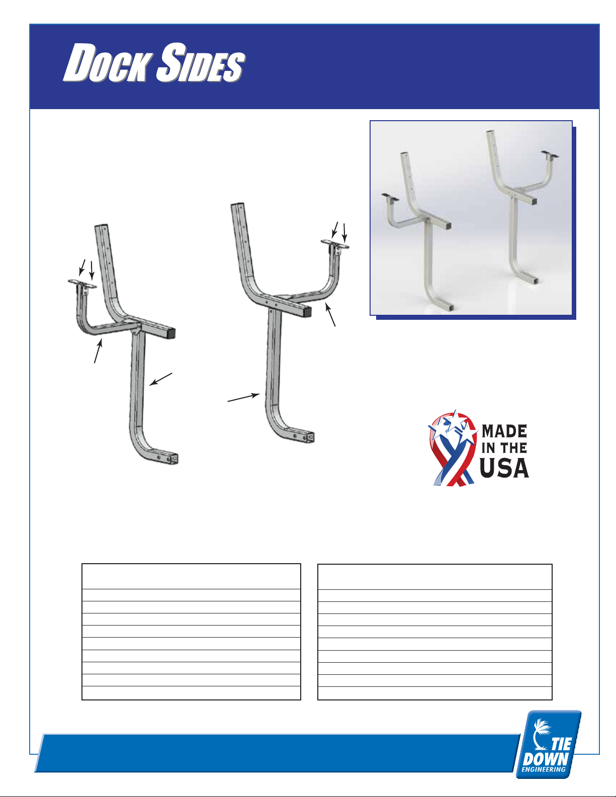
Bench Structure
MAKE YOUR DOCK A DESTINATION
Warnings
Caution should be used when operating electrical tools near
water. Failure to use caution can result in injury or death.
4
3
1
GalvX #86910 / Galvanized #86928
4
3
Tools Required:
2 - 7/16 Wrenches or Sockets
2
GalvX Dual Coat Finish - #86910 Parts List
# Part # Qty Description
1 86910-1LA 1 Bench Frame Left
2 86910-1RA 1 Bench Frame Right
3 86910-2 2 Arm Rest Mount
4 86910-3 4 Arm Rest Bracket
5 10518 6 1/4" x .75" Hex Bolt, Zinc
6 10522 4 1/4" x 2.25" Hex Bolt, Zinc
7 10656 4 1/4" Nyloc Nut
8 17511 4 2" Sq. Tube Plug
Hot Dipped Galvanized Finish - #86928 Parts List
# Part # Qty Description
1 86928-1LA 1 Bench Frame Left
2 86928-1RA 1 Bench Frame Right
3 86928-2 2 Arm Rest Mount
4 86928-3 4 Arm Rest Bracket
5 10518 6 1/4" x .75" Hex Bolt, Zinc
6 10522 4 1/4" x 2.25" Hex Bolt, Zinc
7 10656 4 1/4" Nyloc Nut
8 17511 4 2" Sq. Tube Plug
Instruction Sheet #08189
TIE DOWN ENGINEERING • 255 Villanova Drive SW • Atlanta, GA 30336
www.tiedown.com (404) 344-0000 Fax (404) 349-0401
020513,A1307
Page 2
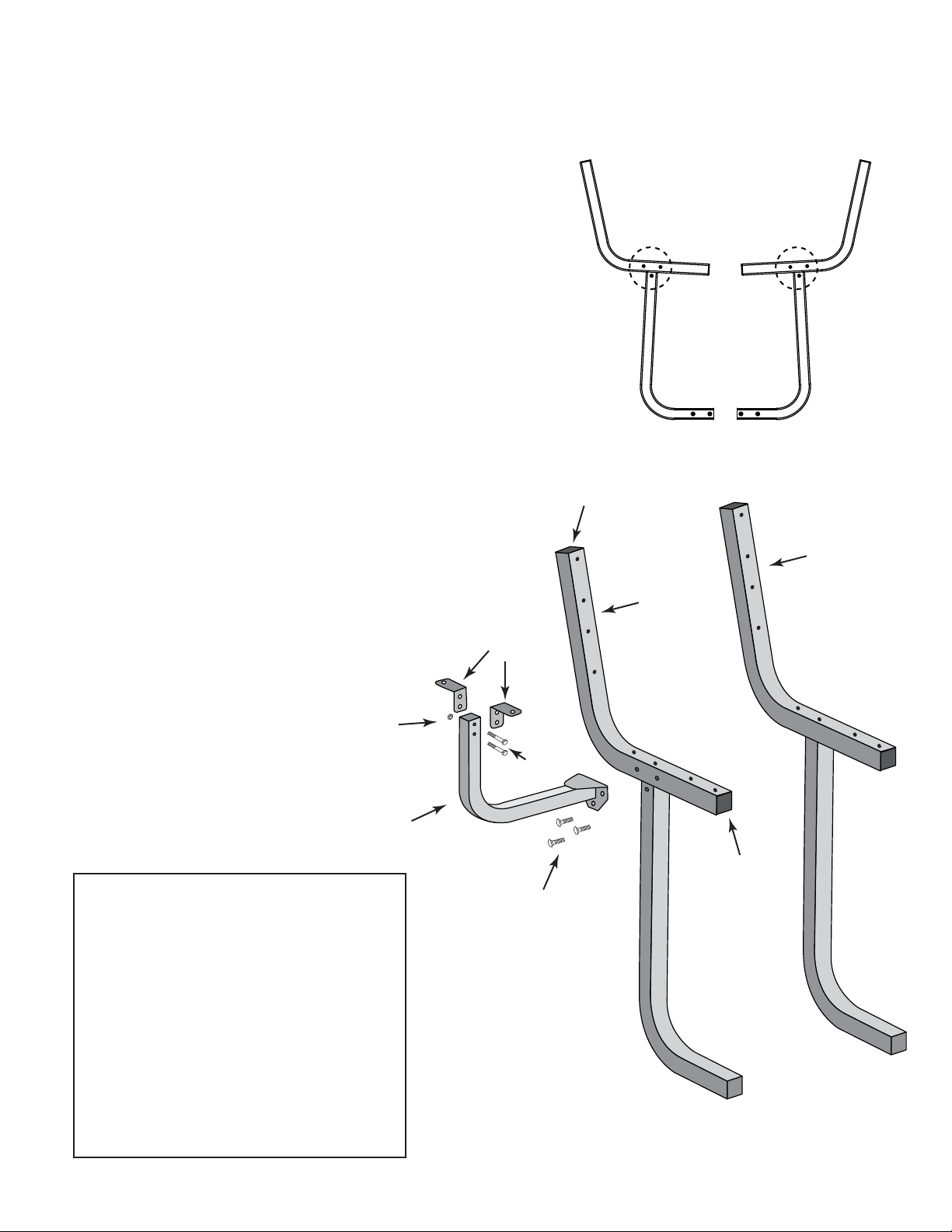
Bench Structure
GalvX #86910 / Galvanized #86928
Assembly Instructions:
1. Place both Bench Frames (Left and right) on a flat
survice. Position the frames so that they face each
other (see right) with arm rest mounting holes on top.
2. Attach the Arm Rest Mounts (3) to Bench Frame
left (1) and right (2) using 3 - 1/4" x .75" bolts (5).
8
Arm Rest Mounting
holes
1
2
3. Attach the Arm Rest Brackets (3) to
the Arm Rest Mounts using
2 - 1/4" x 2.25" bolts (6).
Bench Structure Parts List
# Description
1 Bench Frame Left
2 Bench Frame Right
3 Arm Rest Mount
4 Arm Rest Bracket
5 1/4" x .75" Hex Bolt, Zinc
6 1/4" x 2.25" Hex Bolt, Zinc
7 1/4" Nyloc Nut
8 2" Sq. Tube Plug
2
1
4
7
6
3
8
5
Page 3

Bench Seating and Arm Rest Components
NOT INCLUDED
Shopping List
2 2 x 6 by 10' Wood or Composite Material
1 1 x 4 by 2' Wood or Composite Material
16 1/4" x 2.75" Flat Head Machine Screw
4 1/4" x 1.5" Flat Head Machine Screw
20 1/4" Nyloc Nut
Bench Seat and Back Rest Panels
This pattern is for receivers and bench support structures mounted on 3 foot centers
Qty Size
4 2x6 by 60"
4”
2 x 6 x 60” Wood or Composite Material
Tools Required
Pencil
Tape Measure
Saw
Drill Motor
1/4" Drill Bit
Round Countersink Drill Bit
Sand Paper and Sander
Philips Screw Driver
7/16 Wrench or Socket
5/16” dia.
12”
Secure to bench frame left (#1)and right (#2) with 4 - 1/4" x 2.75" flat head machine screws and 1/4" nyloc nuts.
36”
12”
Arm Rest Panels
12”
Qty Size
2 1x4 by 12”
Mount on arm rest brackets with 3.5" end facing forward.
Secure to arm rest brackets (#4) with 2 - 1/4" x 1.5" flat head machine screws and 2 - 1/4" nyloc nuts.
Part #08189
4”
1.75”
5/16”
6.75”
3.5”
TIE DOWN ENGINEERING • 255 Villanova Drive SW • Atlanta, GA 30336
www.tiedown.com (404) 344-0000 Fax (404) 349-0401
020513,A1303
Page 4

Bench Structure
GalvX #86910 / Galvanized #86928
Parts List
1 2x6 by 5' Wood or Composite Material (4)
2 1x4 by 12” Wood or Composite Material (2)
3 1/4" x 2.75" Flat Head Machine Screw (16)
4 1/4" x 1.5" Flat Head Machine Screw (4)
5 1/4" Nyloc Nut (20)
3 & 5
2
3
5
1
4
5
1
NOTE:
When installing the assembled
bench or attached bench seat and
back rest comments to installed
beach support tube. It is advised to
loosen bolts securing receivers to
the dock or deck. This will allow
slight movement in the receivers to
provide better alignment with the
bench structure.
Installation Instructions:
1. The bolts securing the receiver to the bottom flange of the side panel may need to be loosened to allow proper
alignment and insertion of accessory support tubes.
2. Slide base of accessory tube into receiver until threaded holes align with holes in receiver.
3. Slide eye bolts through receiver side holes and screw into threaded holes in accessory base. Hand tighten all
eye bolts and then use screw driver shaft to tighten one half turn.
1
Eye bolts secure the receiver to the mounting base.
Once the holes are aliened hand tighten all eye bolts.
 Loading...