

Page 1
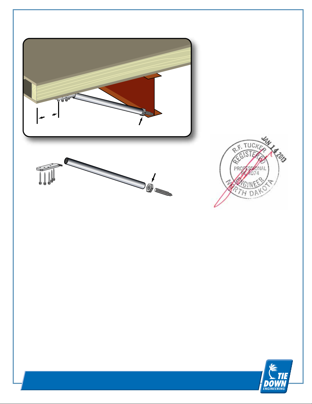
Floor Joist
Top Floor
Bottom Floor
Adjustment/Locking
Nut
Threaded Bolt
6"
I-Beam
Adjustable Outrigger/Diagonal Strut Installation Instructions
Adjustable Outriggers:
24" for 14 ft. wide
Part #59361
36" for 16 ft. wide
Part #59362
Mounting
Plate
Adjustment/Locking
Nut
Support
Screws (5)
Adjustable Outrigger/Diagonal Strut Installation Instructions
1. Determine floor joist area needing support.
2. Set mounting plate on floor joist and secure with 5 (#12X2”) screws provided. Approx. 6” from outer rim joist.
3. Insert threaded adjuster bolt in support tube so it clears I-beam flange when mounting Plate is inserted and
chisel end is placed against the frame. If support tube is too long, simply cut square to desired length.
4. Raise floor joist with jack to desired level before tightening the nut on the threaded bolt, snug fit to 1/4 turn past.
5. Replaces perimeter piers required for window and door support and alignment except as required by the home
manufacturer for larger openings.
6. Built to Federal Manufactured Home & Safety Standards, for maximum openings up to 6’ for 20lb. roof load, 4’ for
a 30 lb. roof load or 3’ for a 40 lb. roof load per set of adjustable outrigger.
7. Outriggers can be used on openings up to 8’ wide on roof loads up to 30 lb. when 2 outriggers are placed on each
side of the opening. Place 1 outrigger on the first floor joist inside the opening and 1 outrigger on the first joist
outside the opening. If the wall jamb falls directly over a joist, place 1 outrigger on that joist and the other one on
the first floor joist inside the opening.
8. Installation of each outrigger should be in accordance with these instructions within 3’ of a pier support or
standard outrigger.
Do not use on homes while being transported.
Note: This component is not designed or intended to replace any foundation supports required by The
home’s manufacturer and is not a repair for damaged joists. These instructions address the capacity
of the adjustable outrigger only.
Instructions #59361-1
Tube
Threaded Bolt
TIE DOWN ENGINEERING • 255 Villanova Drive SW • Atlanta, GA 30336
www.tiedown.com (404) 344-0000 Fax (404) 349-0401
010713,d 270
 Loading...