

Page 1
Installation Instructions and Service Manual
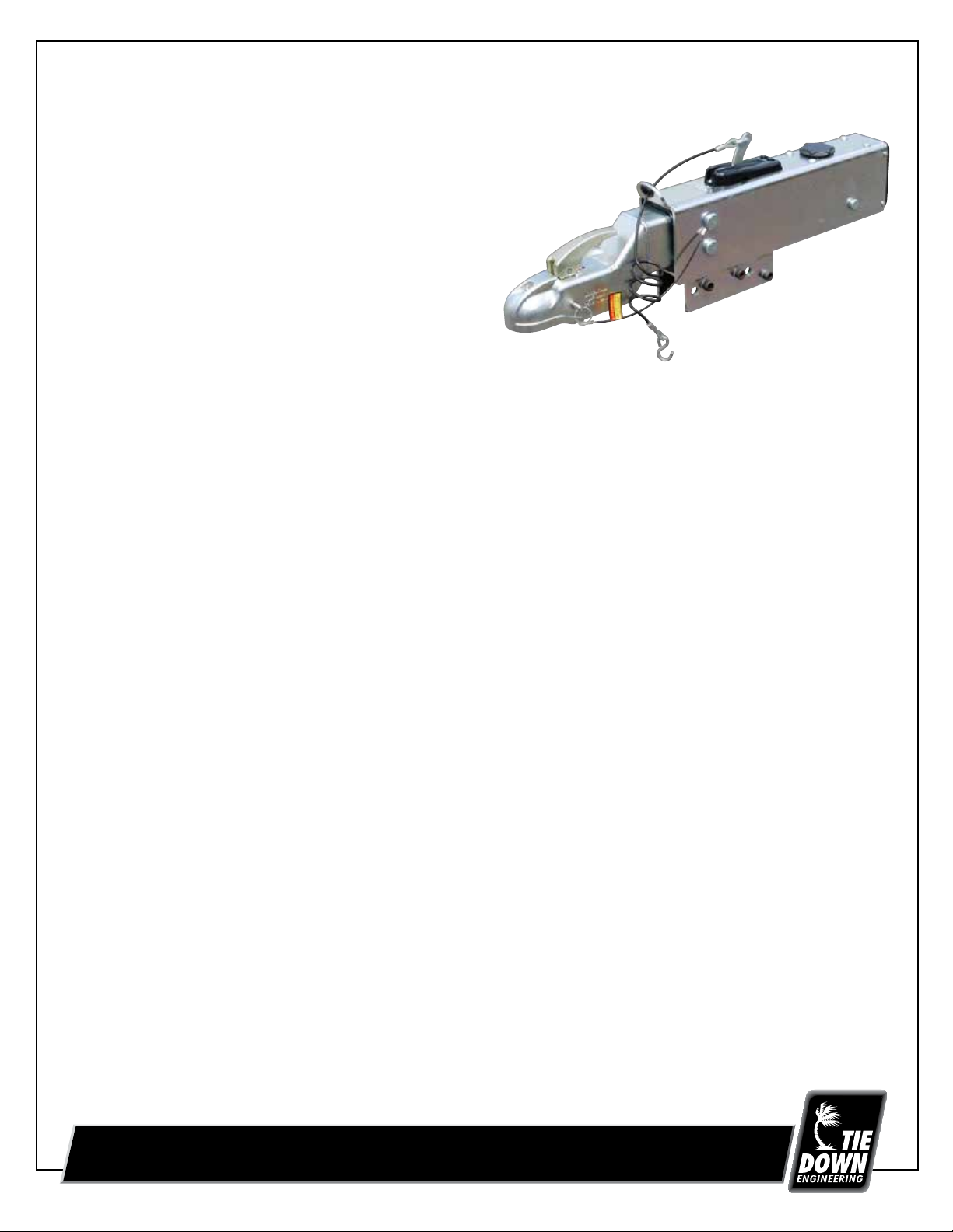
“Raptor” Model 20
Actuator for
Trailer Brakes
20,000 lbs Capacity
Part #70429 - Drum Brake Ready
Part #70428 - Disc Brake Ready
W/Solenoid Installed
IMPORTANT: READ AND UNDERSTAND THE ENTIRE INSTRUCTION/ASSEMBLY PROCEDURE BEFORE INSTALLING YOUR BRAKES AND ACTUATOR.
The Model 20 works by the “surge” or “push” of the trailer toward the tow vehicle. This automatically synchronizes the trailer brakes with
the brakes on the tow vehicle. When the trailer pushes against the tow vehicle, the actuator telescopes together and applies the force to the
master cylinder, supplying hydraulic pressure to the brakes. The built in sealed and independent dampening shock absorber controls
the telescoping shock against the hitch.
Be sure to comply with regulations for brakes in your state. Brake laws sometimes are minimum standards and you may wish to add
additional brakes to your trailer to meet minimum Gross Vehicle Weight Ratings (G.V.W.R.). Note: G.V.W.R. is the Gross Vehicle Weight Rating
which includes the trailer and the load weight as a Total Gross Weight.
Read your tow vehicle owner’s manual on towing capacity and other towing recommendations before installing brakes or this actuator.
The Model 20 Actuator is completely assembled and ready to bolt into place (Tongue sizes: 3”x 4” & 3”x 5”, 9 ga. min.).
1. Bolt the actuator to the tongue-using grade 5 bolts 5/8 inch in diameter, 4 inches long. Attachment strength should equal or exceed
1-1/2 times trailer G.V.W.R.
2. Hydraulic brake lines should be installed on the trailer as described in the installation manual supplied with the brakes. Note: Some disc
brakes require the use of flexible brake lines at the connection POINT on the brake caliper. Follow brake manufacturer instructions.
3. Use only DOT-3 brake fluid in the Model 20 actuator. Use a pressure type brake bleeder to bleed brakes. (This type of brake bleeder is
available at your local automotive parts supply store.) Follow manufacturer’s directions. Or, manually bleed the brakes using a
heavy-duty flat blade screwdriver. Insert the screwdriver and use a pumping action to activate the master cylinder in order to bleed
the brakes. See page 4 for more details.
4. To bleed master cylinder and brakes, install bleeder hose on first wheel cylinder to be bled; if tandem axle trailer, bleed farthest axle
first, and the farthest brake on that axle first. Use a loose end of hose from the bleeder valve submerged in a clear container of
brake fluid to observe bubbling (hose must be submerged into clean brake fluid to keep air from traveling back into the brake cylinder).
Loosen the bleeder screw located in the wheel cylinder one turn; the system is now open to the atmosphere. The bleeding operation for
that brake is complete when bubbling stops. Be sure to tighten bleeder screw securely. Each wheel cylinder must be bled until all air
is out of the lines. Replenish the brake fluid during the bleeding process so the level does not fall below half full level in the master
cylinder reservoir. When bleeding and testing is completed, make sure master cylinder is filled to approximately 3/8” below the top of
the reservoir and filler cap is securely in place.
5. Check with your state motor vehicle department for laws concerning minimum trailer brake requirements. Some states may require
brakes on all axles.
6. Road test trailer a short distance to activate the actuator several times. Check fluid level again. Remember, low brake fluid
levels will result in reduced braking or no braking at all.
7. When testing is completed, make sure master cylinder is filled to approximately 3/8” below the top of the reservoir and filler cap is
securely in place. Road test again to make sure brakes work properly.
Instruction #08199
TIE DOWN ENGINEERING • 255 Villanova Drive SW • Atlanta, GA 30336
www.tiedown.com (404) 344-0000 Fax (404) 349-0401
050713,B1324
Page 2
RATED CAPACITY: Maximum Actuator Capacity: 20,000 lbs. Gross Load; 2,000 lbs. maximum tongue load; minimum tongue
weight is 5% of G.V.W.R.
The actual in-service rating is limited to that of the ball and hitch or the least rated component on the tow vehicle or trailer being used or the
trailer manufacturer’s G.V.W.R. shown on the certification label, whichever is lower (Note: G.V.W.R. is the Gross Vehicle Weight Rating which
includes the trailer and the load weight as a Total Gross Weight).
HITCHING TRAILER
1. The vehicle, towing hitch and ball must have a rating equal to or greater than trailer G.V.W.R.
2. Model 20 will accept 2-5/16” trailer hitch balls with a 20,000# capacity only. Trailer balls larger than 2-5/16” or out of round will not fit
the coupler or may result in coupler failure. Balls smaller than 2-5/16” can cause shock loading and sudden disconnection. Make certain
ball latch is in correct position to retain the hitch ball. Push latch lever down until safety latch engages the hitch ball. Always
insert safety pin into forward hole as a safety lock for the hitch ball coupler prior to towing. Do not tow trailer if coupler is damaged.
3. Connect safety cables or chains using crossed pattern under tongue, or follow trailer manufacturer’s directions.
4. Connect actuator breakaway cable S-hook to the tow vehicle only. Do not connect breakaway cable S-hook to the safety cables or chains.
5. The breakaway system is designed to operate only after the trailer detaches from the tow vehicle and the safety cable/chains have
disconnected from the tow vehicle. The breakaway is not a parking brake. Do not use as such.
6. If the breakaway is accidentally applied while un-hitching, insert a flat bladed screwdriver into the slot on either side of the
plastic cover on top of the actuator. The screw drive blade should go under the spring plate. Pry down on the handle of the
screw driver to release the spring plate. The E-stop arm should fall back and down when released.
7. Any control devices that restrict operation of the actuator cannot be used. This includes certain sway control devices. The actuator must
be free to telescope in response to braking requirements.
8. Equalizing or weight distributing hitches may be used, allow six to eight inches free chain length. DANGER: Tongue weight outside rating
limits will interfere with performance of actuator, and braking system, and the tow vehicle.
9. Automatic “Free-Backing” (backing-up without braking action) is possible with this Actuator when supplied with an electrically operated
“Reverse Lock-Out Solenoid” or coupled with “Free-Backing” drum brakes. To allow “Free-Backing”
without either of those components installed the Operator must manually
“Lock-Out” the Actuator movement while backing up. This is accomplished by
placing a 7/16 X 5” long bolt (or comparable screwdriver) through the upper
hole provided through the actuator housing.
Danger: Failure to remove the bolt/screwdriver after backing will cause
no braking action in normal use. Remember to always remove the
bolt/screwdriver after backing the trailer.
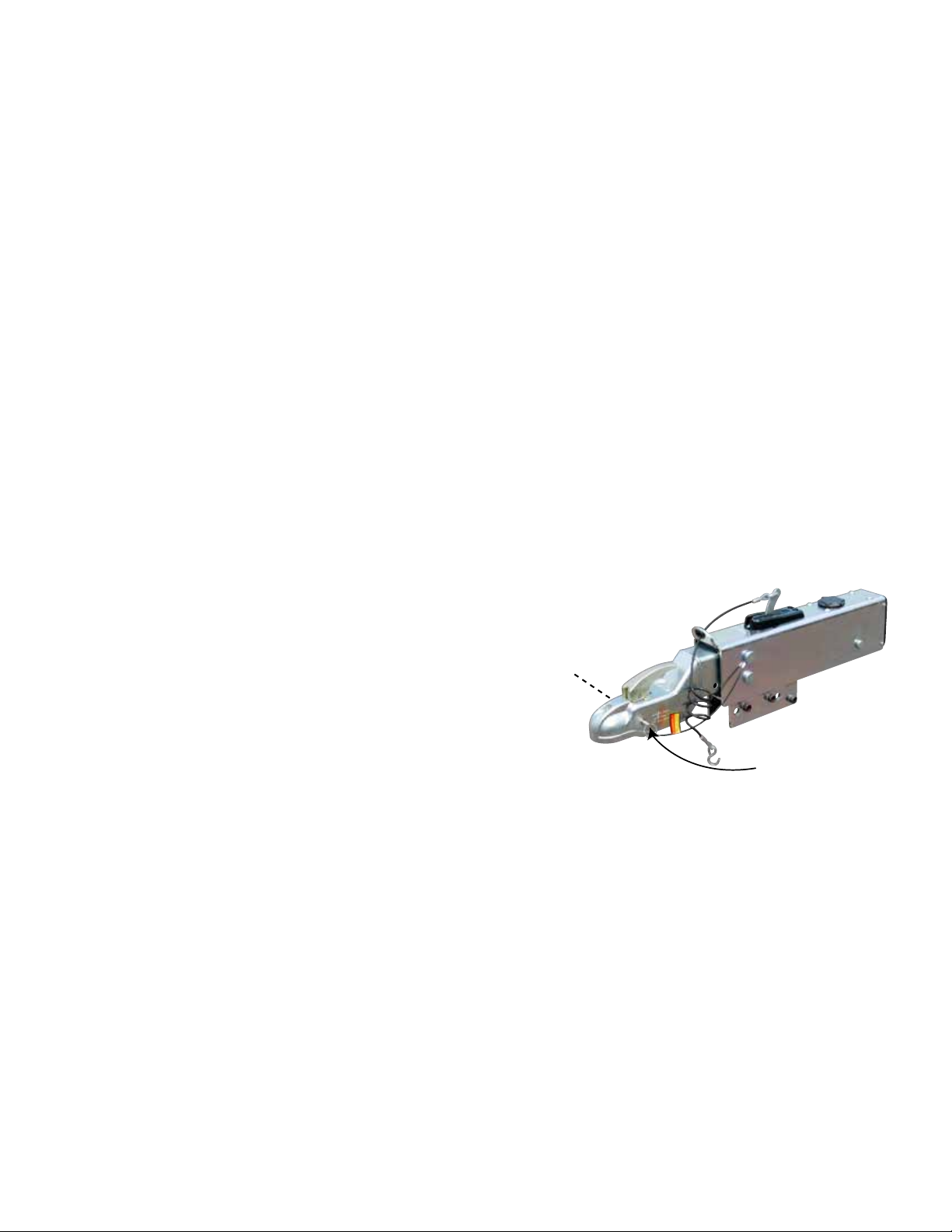
10. Important: The supplied, cable tethered, “Safety Pin” must be installed in
the Coupler Latch hole (see illustration at right) during towing at all times.
Safety Pin
Location
MAINTENANCE
1. Always check the brake fluid reservoir before using trailer. Make sure it is at least half full. If not, re-fill to approx. 3/8 inch below the top
of the reservoir with DOT 3 brake fluid. Check for leaks and repair as required. Never reuse brake fluid.
2. To extend coupler and ball life, coat both with a thin coating of grease. This will also eliminate squeaking. Wipe clean and renew grease
film each time trailer is used. A zerk fitting is installed on the coupler to make this step easier.
3. Examine the actuator for bent parts or wear each time the trailer is used. Replace parts as necessary.
4. There are no user adjustments on the actuator.
5. Excessive actuator travel may indicate a need to adjust the brakes or add fluid to the reservoir or a need to bleed the brakes and check
connections for leaks. Adjust per instructions found in brake installation manual. In general, back off the adjusters on drum brakes from
locked position, as required. Adjust Free-Backing brakes by rotating wheel in forward direction only. Failure to adjust may result in loss of
braking. Disc brakes do not require adjustment, check for pad wear periodically.
6. While towing, if the actuator appears to be knocking against the hitch ball while starting or stopping, check brake fluid reservoir and fill if
below 3/8” full from the top.
Page 2
Page 3

WARNING - DISC BRAKE USE
Actuator models designed for disc brakes do not have a “check valve” installed. Check valves are required for use with drum
brakes. DO NOT use any actuator designed for drum brakes on a trailer with disc brakes installed.
WARNING
Actuator and brakes should always be flushed on the exterior with fresh water after using trailer in corrosive conditions. This includes salt
water, fertilizers and other corrosive materials. Before storing trailer remove brakes and clean thoroughly. It is also wise to repack the
bearings at the same time. Failure to properly and adequately maintain the actuator could cause serious damage, injury or death.
WARNING
The breakaway system is not designed to operate if the trailer does not separate completely from the tow vehicle, or if the tongue goes
under the rear of the tow vehicle.
WARNING
In the event that the breakaway system is used, check all system components (cable, S-hooks, etc.) for proper working order. Replace any
damaged parts with genuine Tie Down parts only.
WARNING
When re-setting the break away system keep hands and fingers clear as you re-set the mechanism, hydraulic pressure held in the system
may cause the assembly to snap back suddenly.
WARNING
AVOID sharp turns, which can cause the actuator to bind or jackknife against the tow vehicle or cause a bend in the tongue. Either can
damage the actuator causing brake failure. AVOID towing trailer across large bumps or dips that may over stress the connection between
the trailer and tow vehicle, as this could result in damage to the actuator.
WARNING
DO NOT REUSE BRAKE FLUID. Always use fresh DOT 3 brake fluid from a fresh container. Failure to maintain proper levels of fluid in the
reservoir will cause brake failure. Never use silicone based brake fluids.
WARNING
Failure to install the hitch pin before towing can result in accidental opening of the coupler hitch latch which can lead to the trailer coming off of the hitch ball causing serious damage, injury or death. If pin will not fit into the latch hole, the coupler is not attached properly.
Re-set coupler on hitch ball.
WARNING
A minimum of 5% tongue weight and a maximum 10% tongue weight of the trailer GVWR must be positioned over the hitch ball. The Trailer
tongue should be parallel to the ground. Too much weight can cause premature brake actuation and loss of control of the towing vehicle.
Too little tongue weight can cause the trailer to fishtail, resulting in loss of control of the tow vehicle and trailer (total trailer weight GVWR
includes weight of the trailer plus load).
WARNING
A loose fit between the coupler and hitch ball can cause the actuator and hitch ball to separate, causing serious damage, injury or death.
Check coupler every time prior to towing and at each stop on long trips. Always make certain that coupler latch safety pin is securely
installed into coupler latch.
WARNING
Brake laws sometimes are minimum standards. Tie Down Engineering strongly recommends brakes on all axles. Read your tow
vehicles owner’s manual on towing capacity and other towing recommendations before installing brakes or this actuator.
WARNING
Never allow the coupler latch safety pin to remain in the reverse lockout position hole. After reverse maneuvering, always insert coupler
latch safety pin back into coupler latch. FAILURE TO REMOVE SAFETY PIN FROM REVERSE LOCK OUT POSITION HOLE WILL PREVENT
FORWARD MOVEMENT BREAKING THAT CAN RESULT IN SERIOUS PROPERTY DAMAGE, INJURY OR DEATH.
Page 3
Page 4

Bleeding Brakes for the 20 Raptor Actuator
1. Secure trailer on level ground. Chock wheels and/
or attach trailer to the tow vehicle to keep the trailer
from moving during the bleeding process
2. Tools Required – one (1) medium to large size flat
blade screw driver, one (1) 3/16” & (1) 5/32” hex key
wrench, one (1) wrench to fit the bleeder valves on
your brakes and brake fluid DOT 3. Do not use
silicone brake fluids. This will cause seal damage and
void your warranty.
3. Pictures 1 & 2 – using the hex key wrenches, remove
the three (3) hex screws holding the top black plastic
cover on top of the actuator.
4. Picture 3 – slide the rectangular metal E-stop spring
catch rearward several inches.
Pic. 1
Pic. 2
5. Picture 4 – fill master cylinder reservoir with DOT 3
brake fluid. NEVER re-use brake fluid. Use only new DOT
brake fluid. Never use silicone based brake fluids.
6. Picture 5 & 6 – Insert the flat blade screw driver in the
Cable attachment loop, with the blade of the screw
driver against the E-stop arm. Pull the handle forward to
pump the master cylinder.
7. Repeat several times and hold to build pressure to bleed
each of the brakes. Follow brake manufacturer’s
instructions for bleeding the brakes.
8. Check the master cylinder reservoir often. Do not allow
the reservoir to empty. When bleeding is completed, fill
reservoir to within 3/8” from the bottom of the threads.
DO NOT OVER FILL.
See next page
Pic. 3
Pic. 4
Pic. 5 Pic. 6
Page 4
Page 5

Bleeding Brakes for the 20 Raptor Actuator
(Continued)
9. Reassemble E-stop spring latch and cover as shown
in Pictures 7 thru 11. Slide the spring catch back into
position so that the holes in the plate, line up with the
holes in the cover. Place plastic cover over the plate,
apply loc-tite or thread locker to threads and reinstall
the three (3) hex head screws.
10. Test brakes in a protected area such as a parking lot or
side street.
Pic. 7
Pic. 9Pic. 8
Pic. 10 Pic. 11
Emergency Stop Cable or E-stop Cable
The Model 20 actuator is supplied with an emergency stop system that applies the brakes in the unlikely
situation were the trailer becomes disconnected from the tow vehicle. The cable is PVC coated and coiled for
convenience. On one end the cable is connected to a lever arm on top of the actuator. The other end of the cable
has a hook to connect to the tow vehicle. Should the trailer become disconnected from the tow vehicle (both coupler
and/or chains) the E-stop cable would pull the lever and activate the master cylinder. A steel spring lock keeps the
pressure on the brakes until manually released.
1. When towing the vehicle, connect the end of the E-stop cable to the tow vehicle.
2. Never connect the E-stop cable to the safety chains or cables.
3. Connection point should be a position on the tow vehicle that is different from the safety cables or chains.
Continued on next page
Page 5
Page 6

WARNING: It is possible that the E-stop can be activated by pulling on the cable in various ways.
1. Forgetting to disconnect the E-stop cable from the tow vehicle and pulling tow vehicle away from the trailer.
This would pull the lever and activate the brakes.
2. Stepping on the E-stop cable with enough force to pull the lever and activate the brakes.
3. Attaching the E-stop hook in a way that is too tight and causes the cable to be pulled when making turns while
towing the trailer.
4. Wrapping the E-stop cable around the actuator or trailer tongue reducing the amount of free play in the cable.
5. Leaving the E-stop cable dragging on the ground, causing the cable to grab an object on the road.
RELEASING THE E-STOP
Pic. 1
Always check the position of the E-stop lever to
make sure it is not in a locked position. Lever should
be able to touch the rear of the slot in the plastic
cover when not activated.
1. Picture 1 shows a released E-stop lever position.
Picture 2 shows an activated E-stop
lever position.
2. To release, use a flat bladed screw driver to
pry up the steel E-stop spring picture 3.
3. Insert flat bladed screwdriver under the steel
spring plate and push the handle of the screw
driver down, prying the spring plate up to release
the E-stop lever. Picture 4.
4. E-stop lever should move freely after release
picture 5.
Brake “Engaged”
Normal Position
Pic. 2
Page 6
Place screwdriver head
under the spring plate.
Pic. 3
Pic. 4
Pic. 5
Page 7

TIE DOWN ENGINEERING LIMITED ONE YEAR WARRANTY
Limited Warranty TIE DOWN ENGINEERING Inc (“TIE DOWN”) warrants its products to be free from defects in material and workmanship for one year from
date of delivery to the original purchaser when properly installed, used and maintained by the purchaser.
This warranty does not apply to damage or loss caused by any or all of the following circumstances or conditions:
• Damage caused during installation.
• Parts, accessories, materials or components used with or replacing any TIE DOWN braking system not obtained from or approved in writing by TIE DOWN.
• Misapplication, misuse and failure to follow the directions or observe cautions and warnings on installation, operation, application, inspection or
maintenance specified in any TIE DOWN quotation, acknowledgement, sales literature, specification sheet or installation instruction and service
manual (“applicable literature”).
• Use of product in any other application other than those described in TIE DOWN’s product information materials.
If any TIE DOWN products are found upon TIE DOWN’s examination to have been defective when supplied, TIE DOWN will either: credit the purchaser’s
account for the purchase price of the TIE DOWN product; replace the TIE DOWN product; or repair the product. TIE DOWN has sole discretion in choosing
which option to provide. For this LIMITED WARRANTY to apply, TIE DOWN must receive notice of the alleged defect within 30 days of either the discovery
of the alleged defect or the expiration of the warranty period, whichever is earlier. Any claim not made within this period shall conclusively be deemed
waived.
If requested by TIE DOWN, purchaser shall return the alleged defective product to TIE DOWN for examination at purchasers expense. TIE DOWN will not
pay for expenses incurred in returning a product to TIE DOWN without TIE DOWN’s prior written authority. TIE DOWN shall not be liable for any other
expenses purchaser incurs to remedy any defect. Purchasers waive subjugations on all claims under any insurance.
Limitation of Liability: It is expressly agreed that the liability of TIE DOWN is limited and TIE DOWN does not function as an insurer. THE REMEDIES SET
FORTH IN THIS WARRANTY SHALL CONSTITUTE THE EXCLUSIVE REMEDIES AVAILABLE TO THE PURCHASER OR USER AND ARE IN LIEU OF ALL OTHER
REMEDIES, EXPRESS OR IMPLIED. THE LIABILITY OF TIE DOWN, WHETHER IN CONTRACT, IN TORT, UNDER ANY WARRANTY OR OTHERWISE, SHALL NOT
EXCEED THE PURCHASE PRICE OF THE PARTICULAR PRODUCT MANUFACTURED, SOLD OR SUPPLIED BY TIE DOWN.
To Obtain Technical Assistance: To enable TIE DOWN to respond to a request for assistance or evaluation of customer or user operating difficulty, please
provide at a minimum the following information by calling 404-344-0000:
• Model number, serial number and all other data on the specific component which appears to be involved in the difficulty.
• The date and from whom you purchased your TIE DOWN product.
• State your difficulty, being sure to mention at least the following: Application, Nature of load involved, and Weight of the load.
Field Service: If field service at the request of the purchaser is rendered and the difficulty is found not to be with TIE DOWN’s product, the purchaser shall
pay the time and expense (at the prevailing rate at the time of service) of seller’s field representative (s). Charges for service, labor and other expenses
that have been incurred by the purchaser, its customer or agent without prior written authorization of TIE DOWN will not be accepted.
TIE DOWN EXTENDS NO WARRANTY, EXPRESS OR IMPLIED, ON PRODUCTS NOT MANUFACTURED BY TIE DOWN OR TO TIE DOWN’S DESIGN SPECIFICATION,
INCLUDING BUT NOT LIMITED TO SUCH ITEMS AS TIRES, BRAKES, BEARINGS, HOSE AND TUBING. PURCHASER’S RECOURSE SHALL BE LIMITED TO ANY
WARRANTY OF THE RESPECTIVE MANUFACTURERS.
THIS WARRANTY EXCLUDES ALL IMPLIED WARRANTIES OF MERCHANTABILITY OR FITNESS FOR A PARTICULAR PURPOSE OR ANY PURPOSE.
THIS WARRANTY DOES NOT COVER NOR EXTEND TO INCIDENTAL OR CONSEQUENTIAL DAMAGE. Some states do not allow the exclusion or limitation of
incidental or consequential damages, so the above limitation or exclusion may not apply to you. This warranty gives you specific legal rights, and you may
also have other rights which vary from state to state.
No representative has authority to make any representation, promise or agreement except as stated in this Limited Warranty. TIE DOWN reserves the right
to make design and other changes upon its products without any obligation to install the same on any previ ously sold or delivered products.
DUE TO THE WIDE VARIATION IN USES TO WHICH TIE DOWN PRODUCTS (WHEELS, HUBS, BRAKES, ETC.) ARE SUBJECTED BY USERS, WE ARE UNABLE TO
SPECIFY CARRYING CAPACITIES OR SPEEDS FOR A PARTICULAR APPLICATION. THEREFORE, THE MANUFACTURER MUST TEST HIS EQUIPMENT UNDER THE
MOST SEVERE CONDITIONS TO DETERMINE THAT TIE DOWN PRODUCTS ARE SUITABLE.
THERE ARE NO WARRANTIES WHICH EXTEND BEYOND THOSE DESCRIBED ABOVE. EFFECTIVE JANUARY 2005 THIS WARRANTY SUPERSEDES ALL PRIOR
WARRANTIES, WRITTEN OR IMPLIED.
Page 7
TIE DOWN ENGINEERING • 255 Villanova Drive SW • Atlanta, GA 30336
www.tiedown.com (404) 344-0000 Fax (404) 349-0401
Page 8

Model 20 - 20,000 lbs. Capacity
031014,B1324
9
Part #70428 Disc Brake
Part #70429 Drum Brake
7
2
8
1
6
1C
3
10
1B
1A
4
1A & 5
4
7
4
2
Item # Part # Description
1A 70403-20K Disc Brake Model 20 - Master Cylinder Kit
Includes: master cylinder and cap and 4 mounting screws
1A 70703-20KD Drum Brake Model 20 - Master Cylinder Kit
Includes: master cylinder and cap and 4 mounting screws
1B 11286 Disc Brake Solenoid - used with Disc brake actuators
1C 17028SA Dampener Cylinder (each) 2 required
2 70404K Wear Pad Kit - Includes: upper and lower wear pads
3 70407K Emergency Stop Lever and Spring
4 70408K Actuator Pin Kit - Includes: 3 pins with retainers and pin kit
5 48986A Master Cylinder Cap with internal bladder
6 50306 Safety Pin and Cable Assembly
7 50307K Emergency Stop Cable with Connector Link
8 70409K Latch Kit for Model 20
9 70405K Cover for Emergency Stop Lever and Spring and 3 mounting screws
10 70406 Rear Cover for model 20
 Loading...