

TIE PLUS24, PLUS36, PLUS64, Businesscom PLUS 24, Businesscom PLUS 36 Installation And Maintenance Manual
...
SYSTEM PRACTICE 01651 IMG
BUSINESSCOM
24/
Installation
Issue
This manual should be read in its entirety before
attempting to install or program the system.
This manual has been developed by TIE/communications. Inc. It is intended for the use of its customers and service
personnel.
Any
comments or suggestions for improving this manual would be appreciated. Forward your remarks to:
and Maintenance
2-O
Attention: Manager, Technical Publications
February
TIE/communications, Inc.
5 Research Drive
Shelton, CT 06484
information in this manual is subject to change. While every effort has been made to eliminate errors, the
company disclaims liability for difficulties arising from interpretation of the information contained herein.
1986 by TIE/communications, Inc. All Rights Reserved.
BUSINESSCOM PLUS is a trademark of TIE/communications, Inc.
Form 0006 April 1963
005093150
Printed in U.S.A.
BUSINESSCOM PLUS
REVISION CONTROL
REVISIO
1-O
2-o
DATE
31 DEC 85 Initial Release of Manual. Software Level B.
7 FEB 86
Incorporated additional programming conditions in Section 4.
CHANGE
OF BUSINESSCOM PLUS ILLUSTRATIONS
FIGURE #
Figure l-l
Figure l-2
Figure 1-3
Figure 1-4
Figure
Figure 5-lb
Figure
Figure 6-l
Figure 6-2
Figure 6-3
Figure 6-4
Figure 6-5
Figure 6-6
Figure 6-7
Figure 6-8
Figure 6-9
Figure 6-10
Figure 6-11
Figure 6-12
Figure 7-1
Figure 7-2
Figure C-l
Figure C-2
TITLE
LINE STANDARD 5 LINE EXECUTIVE DISPLAY
TELEPHONES.
8, LINE STANDARD TELEPHONES
8, LINE EXECUTIVE DISPLAY TELEPHONES
.........................................
.....................
.............
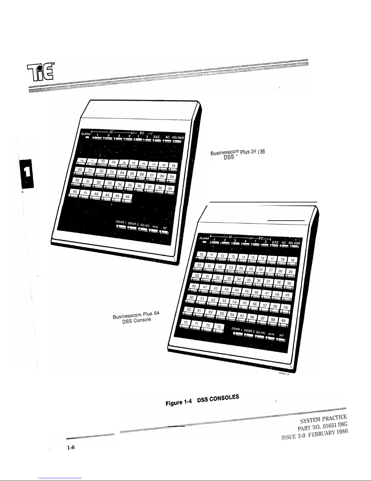
DSSCONSOLES.........................................l- 6
BUSINESSCOM PLUS 24 INSTALLATION LAYOUT.
BUSINESSCOM PLUS 36 INSTALLATION LAYOUT.
BUSINESSCOM PLUS 64 LAYOUT.
BACKGROUND INSTALLATION.
DOOR CHIME BOX INSTALLATION
DSS CONSOLE INSTALLATION
.............................
......................
..........................
EXTERNAL ALARM SIGNALS TO STATIONS INSTALLATION
EXTERNAL PAGING CONTACTS WIRING.
EXTERNAL PAGING OUTPUT WIRING
....................
.......................
MUSIC ON HOLD (EXTERNAL) INSTALLATION
MUSIC ON HOLD CONTACTS WIRING
........................
.............
.............
.............
......
.................
BUSINESSCOM PLUS 64 B-PFU-A PCB POWER FAILURE STRAPS .
REMOTE BUSY LINE INDICATION (FAX) INSTALLATION
SPEAKERPHONE PCB INSTALLATION.
WALL-MOUNTING INSTALLATION
PROGRAMMING SWITCH-WR
.............................
ENTERING THE PROGRAMMING MODE
PRINTED CIRCUIT BOARD
OFF-PREMISES EXTENSION CONNECTIONS
.....................
..........................
......................
.........................
..................
.........
PAGE
1-3
1-4
l-5
6-3
6-4
6-7
6-8
6-9
6-12
6-14
7-3
7-4
C-5
C-5
INDEXOFBUSINESSCOMPLUSTABLES
FIGURE #
l-l
1-2 SPECIFICATIONS, BUSINESSCOM PLUS 36 . . . . . . . . . . . . . . . . . .
‘lhble 1-3 SPECIFICATIONS, BUSINESSCOM PLUS 64 . . . . . . . . . . . . . . . . . . l-11
‘lhble 3-1
‘lhble 5-l BUSINESSCOM PLUS 24
5-2
5-3
8-l
C-l
C-2
C- 3 “B” BLOCK STATION LOCATIONS
TITLE
SPECIFICATIONS, BUSINESSCOM PLUS 24 . . . . . . . . . . . . . . . . . . . 1-9
FORM, BUSINESSCOM PLUS 24 I36 I64 . . . . . . . . . . . . . . . 3-4
. . . . . . . . . . . . . . . . . . . . . . . 5-14
BUSINESSCOM PLUS 36 . . . . . . . . . . . . . . . . . . . . . . . 5-15
BUSINESSCOM PLUS 64
TELEPHONE TEST PROCEDURE
B-STUD PCB SPECIFICATIONS.
B-STUD STATION BLOCK CONNECTIONS.
.......................
..........................
...........................
...................
..........................
PAGE
5-16
8-2
C-6
C-7
C-8

BUSINESSCOM PLUS
ELECTRONICKEYTELEPHONESYSTEMS
INTRODUCTION
Section 1, SYSTEM DESCRIPTION, introduces the reader to the system. Section 1 contains general descriptive information
about the system components, and details the telephone company, site and FCC requirements. It also includes a specification
table.
Section 2, FEATURES, provides a detailed description of every feature available in the system. Additional data on key callouts,
flash and signaling patterns, and display messages is also included.
Section 3, HARDWARE CONFIGURATION, allows the reader to develop the Order Sheet. The Order Sheet is used to record
the equipment (hardware) requirements of the installation site.
Section 4, SOFTWARE CONFIGURATION, consists of the instructions necessary to configure the system programmable
options. The data base developed in this section is entered on the Program Record Form (Appendix A). The codes on the
Program Record Forms are entered into system memory during installation.
Section 5, INSTALLATION, includes all the information required to successfully install the system.
Section 6, INSTALLATION OF OPTIONAL EQUIPMENT, contains description and installation data on each piece of
optional equipment that can be used with the system.
Section 7, PROGRAMMING, tells the reader how to enter the data base recorded on the Program Record Forms into system
memory. All systems must be programmed to some degree before being operational.
Section 8, MAINTENANCE, is the final section of the manual and provides maintenance instructions for the system.
Appendix A contains the Program Record Form.
Appendix B contains the Operational Specifications.
Appendix C contains information on the Off-Premises Extension.
.

ELECTRONICKEYTELEPHONESYSTEMS
CONTENTS
1.
INTRODUCTION.
2. SYSTEM DESCRIPTION.
Key Service Unit And Power Supply
Telephones
Options. .........................
3. SPECIFICATIONS.
4. SITE REQUIREMENTS.
5. FCC AND TELCO REQUIREMENTS
Notification To
Incidence Of Harm
Hearing Aid Compatibility
6. RADIO FREQUENCY INTERFERENCE.
1.
1.01
INTRODUCTION
The System Description Section provides basic
..................... l-l
............... l-l
........................
...................
...............
.................
..................
............. l-8
.......
PAGE
...... l-l
1-2
1-7
1-7
1-7
.... l-8
information pertaining to the Businesscorn Plus
24 family of Electronic Key Telephone Systems.
2.
2.01
SYSTEMDESCRIPTION
The Businesscom Plus use micro-
processors as the main processors and additional
processors for tasksharing between the Main Processing Unit
and the station Printed Circuit Boards Also used is
a space division matrix.
2.02 The Businesscom Plus 24 has a maximum capacity
of eight Central Office (CO) lines, six Intercom links
and 24 stations. Privacy is provided on all calls.
2.03
The Businesscom Plus 36 has a maximum capacity
of 12 CO lines, six Intercom links and 36 stations.
Privacy is provided on all calls.
2.04
The Businesscom Plus 64 has a maximum capacity
of 24 CO lines, six Intercom links and 64 stations.
Privacy is provided on all calls.
KEY SERVICE UNIT AND POWER SUPPLY
1.02 This section describes the various components of
the system, stations, instruments, specifications, site
and FCC requirements.
1.03 Documents which should be used in conjunction
with this manual are the User’s Guide for the
Multibutton Telephone (PN 01651 MBB), the User’s Guide
for the Executive Display Telephone (PN 01651 EDB), and
the User’s Guide for the attendant telephone
01651 ACB).
2.05
The Key Service Units house replaceable
that control the system. The are
designed for wall mounting.
2.06
The power supply units have input requirements of
and are designed for wall mounting.
TELEPHONES
OPTIONS
2.07 The Businesscom Plus can use
telephone from the Businesscorn Plus family.
2.08
Businesscorn Plus 8, 12, 24 Line Standard telephones (Figures l-l and 1-2) are equipped with
Door Chime Box
2.12 Door Chime Boxes can be installed to provide
Boxes do not utilize station positions.
speakers to accommodate tone signaling and Intercom voice
tone announcements. Various keys have red Light Emitting
Diodes which provide a visual indication of call or
DSS Consoles
2.13 DSS Consoles permit easy and quick access to many
feature status. Ten function (DSS) keys are available and can
be used as storage bins for Speed Dial and/or Intercom
a station position.
numbers. A slide control is used for speaker volume
adjustment. A microphone is standard hardware that permits
Handsfree Reply On Intercom (Figure l-1).
External Page Zones
2.14 External zones can receive Background Music, CO
2.09
Businesscorn Plus Line Executive Display
telephones (Figures l-l and l-2) are equipped with
all the features of Standard telephones as well as some extras
as detailed in the next paragraph.
2.10 Executive Display telephones are factory equipped
with speakerphones. Speakerphones permit two-way
handsfree conversations. CO line keys have both red and
green that give a visual indication of CO line status. A
liquid crystal display is provided that displays time and date
and can be used as a visual indication of CO and Intercom
numbers.
Single Line Telephones
2.15 Single line telephones can be used for locations not
be installed on premises or as Off-Premise Extensions
DTMF (2500 type), with standard tone or bell ringers. Single
line telephones have limited access to certain Businesscom
Plus features, including:
Intercom features (outbound)
Ringing Intercom calls (inbound)
2.11 The following lists and describes the Businesscorn
Plus family of telephones:
Businesscorn Plus Family of Telephones
Telephone
Description
Standard 3 Line
Standard 5 Line
12TDX
24TS
Display 5 Line
Standard 8 Line
24TDX Display 8 Line
36TS
36TDX
64TS
64TDX
Standard 12 Line
Display 12 Line
Standard 24 Line
Display 24 Line
.
Direct CO Queue Group Access
Direct CO Line Access
Pickup of incoming calls and calls on System Hold
Call Transfer (Screened or Unscreened)
Incoming CO Audible Assignments
Toll Restriction
Single line sets require special KSU hardware consider-
ations, and reduce the quantity of key phones in a given
system. The maximum number of Single line telephones is
approximately half of the system telephone maximum (see
Appendix C for details).
NOTE: For simplification, this manual refers to Single line
telephones as whether or not the single line set is
installed off-premises.
signaling from outside the building. Door Chime
features and all stations. DSS Consoles do not utilize
Audible, Paging, and External Alarm Signals.
requiring key telephones. Single line telephones can
Single-line sets can be rotary, pulse (500 type) or
3 Line Standard Telephone
5 Line Standard Telephone
Figure l-l
LINE STANDARD AND 5 LINE EXECUTIVE
1-3
Standard Telephone
Line Standard Telephone
Figure 1-2
STANDARD TELEPHQNES
8 Line Executive Display Telephone
24 Line Executive Display Telephone
Figure 1-3
LINE EXECUTIVE DISPLAY TELEPHONES
Console
Speakerphones
5.
2.16 Speakerphones, which can be installed in Standard
telephones, permit handsfree CO conversations. The
5.01 Rules and regulations for the operation and
maximum number of speakerphones permitted in each
system is as follows:
established by the Federal Communications Commission
(FCC). According to Part 68, “Connection of Terminal
System
24
36
64
Maximum
12
12
24
Equipment to the Telephone Network” and its amendments,
several actions are required before and during the installation
of customer-provided telephone equipment. These actions
are listed and described in the following paragraphs.
FCC AND TELCO REQUIREMENTS
installation of telephone equipment have been
3.
3.01
SPECIFICATIONS
Refer to Tables l-2 and 1-3 for technical
NOTIFICATION TO TELCO
5.02 As owner of this telephone system, you must give the
specifications pertaining to the Businesscom Plus
24
systems.
company (telco) before connecting or disconnecting it:
(1) Sufficient notice of your intention to use privately owned
telephone equipment.
4.
SITE REQUIREMENTS
The particular lines to be used (telephone numbers
xxx-xxxx through xxx-xxxx).
4.01 The KSU should be installed in a clean, dry, secure
location that prevents access by unauthorized
personnel. This location, as detailed in Section 5, should
comply with Bell Functional Product Class Criteria of
(3) Model: Businesscom Plus
FCC Registration Number:
Ringer Equivalence:
Registered Jack:
September 1978, in publication PUB 48002 as stated in
3.4.3.2, paragraph C-Indoors With Environmental Control.
The room must have adequate ventilation and have a
NOTE:
of the installation.
temperature range that does not exceed 32 to 113 degrees
F (0 to 45 degrees C) with a 10 to 95% noncondensing,
relative humidity.
4.02
The installation site should provide ample room to
INCIDENCE OF HARM
5.03
mount the KSU on the wall along with the necessary
connecting blocks and any ancillary equipment. The
installation site should not be located in areas subject to static
electricity (e.g., dry copiers), vibration (e.g., heavy
machinery), or in areas likely to be (e.g., basement
level).
must, whenever practical, notify the customer that service
may be temporarily discontinued. The company
must also attempt to inform the customer before actually
disconnecting service. The telephone company must provide
customers with an opportunity to correct the problem and
must advise customers of their right to bring complaint
4.03
The customer must provide a dedicated NEMA
procedures before the FCC.
outlet with a and a 15 Amp
circuit. A separate earth ground is required in addition to the
third-wire ground on the AC circuit. If a music source or
optional external paging equipment is installed, it must be
connected to an AC circuit other than the system’s dedicated
AC line. ONLY THE POWER SUPPLY SHOULD BE
CONNECTED TO THE DEDICATED AC OUTLET.
following information to the operating telephone
Have telco drop the connectors within 25 feet
If customer-provided equipment is causing harm to
the telephone network, the telephone company
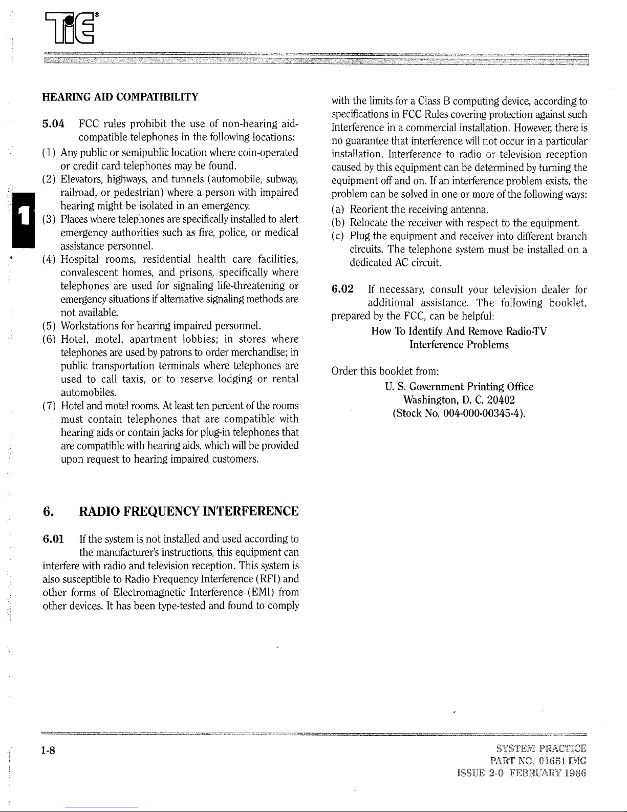
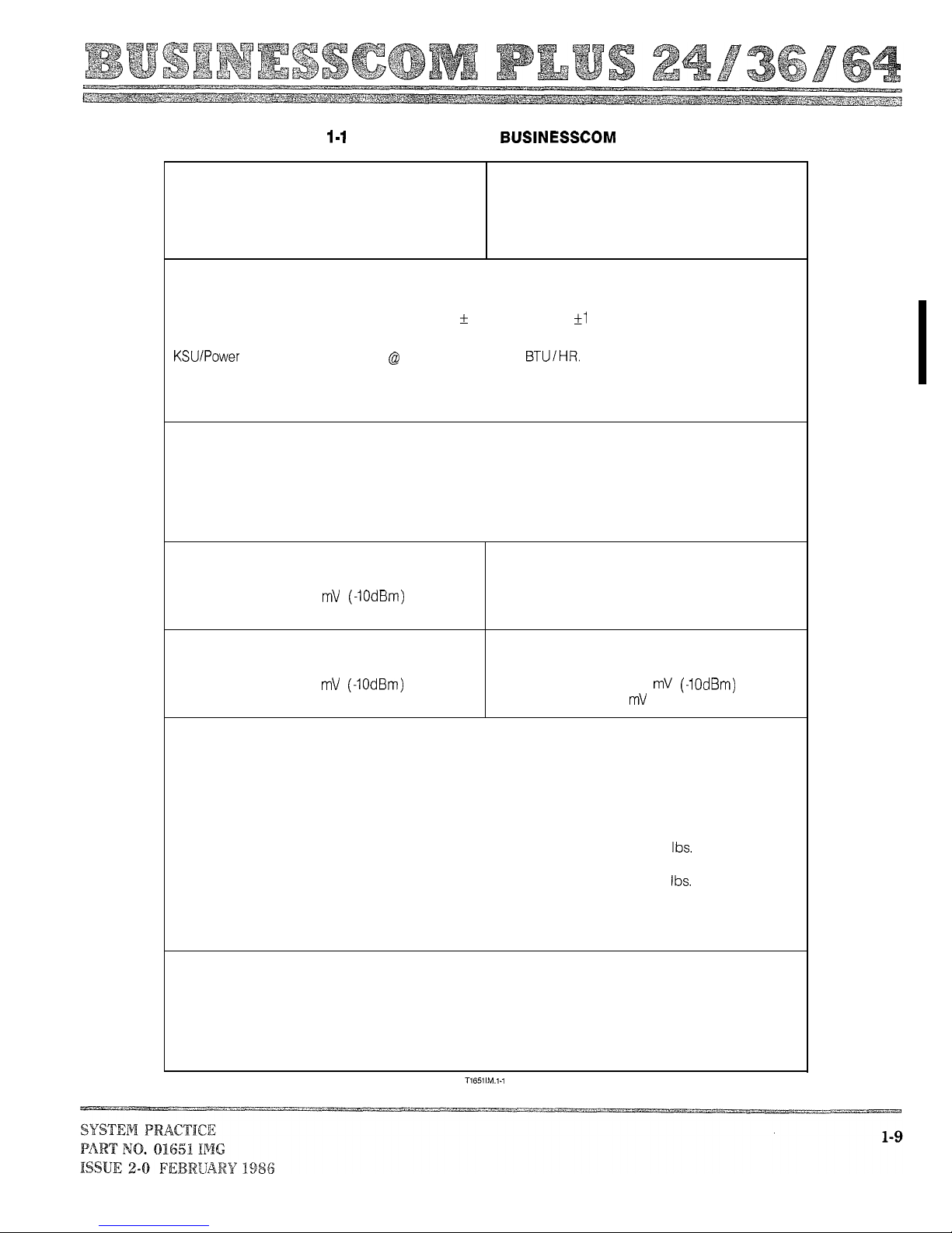
Table SPECIFICATIONS, PLUS 24
GENERAL SPECIFICATIONS
System Capacity:
CO Lines
Intercom Talkpaths
Key Telephones
MAX. NO.
8
6
24
System Capacity:
Speakerphones
OPX Telephones
MAX. NO.
12
12
ELECTRICAL SPECIFICATIONS
Power Requirements: (AC Supply Must Be Dedicated)
KSU/Power Supply Operating Range: 117 VAC
10%
60 Hz Hz
Power Dissipation:
Supply Unit: 340 Watts 2.9 Amp
1160
Grounding Requirements:
KSU Ground lug, 14 AWG or larger copper wire to cold water pipe or known good earth ground
Cable Requirements:
Four conductor (two-pair twisted) station wire. 1000 feet (304.8 m) using 24 AWG. 1500 feet (457.2 m)
using 22 AWG.
Door Chime Box: 500 feet (152.4 m) using 24 AWG.
Console: 1000 feet (304.8 m) using 24 AWG or
500
feet (152.4 m) if two consoles are used and one is
used as a BLF (Busy Lamp Field)
Background Music Specifications:
Input Impedance: 600 OHMS
Input Level: Nominal 250
Limit for Alarm Circuit:
Loop Resistance: 1000 OHMS Max.
Maximum Input: 1 Volt RMS
Music On Hold Specifications: External Paging Specifications:
Input Impedance: 600 OHMS Output Impedance: 600 OHMS
Input Level: Nominal 250 Output Level: Nominal 250
Maximum Input: 1 Volt RMS Maximum Output: 400 RMS
MECHANICAL SPECIFICATIONS
Dimensions and Weights:
KSU:
Power Supply:
Executive/Key Telephone:
Door Chime Box:
DSS Console:
16.8 in.
430.0 mm
12.1 in.
310.0 mm
3.1 in.
80.0 mm
5.1 in.
131.0 mm
2.0 in
52.0 mm
x 21.5 in. x 7.8 in.
x 550.0 mm
x 14.2 in.
x 200.0 mm
x 4.8 in.
x 363.5 mm x 122.0 mm
x 8.0 in. x 8.6 in.
x 205.0 mm x 221.0 mm
x 3.9 in. x 1.4 in.
x 99.0 mm x 35.0 mm
x 7.4 in. x 8.8 in.
x 189.0 mm x 224.0 mm
26.5 Ibs.
12.0 kg
12.8 Ibs.
5.8 kg
2.2
1.0 kg
0.4
0.2 kg
1.3 Ibs.
0.6 kg
ENVIRONMENTAL SPECIFICATIONS
Environmental Operating Conditions:
Temperature:
KSU and Telephones: 0 to 45 degrees C
Door Chime Box: -20 to 60 degrees C
(32 to 113 degrees F)
( -4 to 140 degrees F)
Humidity: 10% to 95% noncondensing
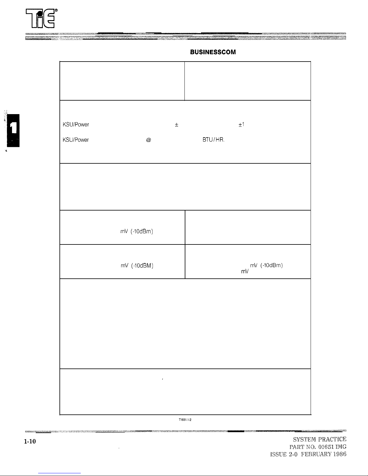
Table 1-2 SPECIFICATIONS, PLUS 36
GENERAL SPECIFICATIONS
System Capacity:
CO Lines
Intercom Talkpaths
MAX. NO.
12
6
System Capacity:
Speakerphones
OPX Telephones
MAX. NO.
12
18
Stations 3 6
ELECTRICAL SPECIFICATIONS
Power Requirements: (AC Supply Must Be Dedicated)
Supply Operating Range: 117 VAC 10%
60 Hz Hz
Power Dissipation:
Supply Unit: 480 Watts 4.1 Amps
1638
Grounding Requirements:
KSU Ground lug, 14 AWG or larger copper wire to cold water pipe or known good earth ground
Cable Requirements:
Four conductor (two-pair twisted) station wire. 1000 feet (304.8 m) using 24 AWG. 1500 feet (457.2 m)
using 22 AWG.
Door Chime Box: 500 feet (152.4 m) using 24 AWG.
Console: 1000 feet (304.8 m) using 24 AWG or 500 feet (152.4 m) if two consoles are used and one IS
used as a BLF (Busy Lamp Field)
Background Music Specifications:
Input Impedance: 600 OHMS
Input Level: Nominal 250
Limit for Alarm Circuit:
Loop Resistance: 1000 OHMS Max.
Maximum Input: 1 Volt RMS
Music On Hold Specifications:
External Paging Specifications:
Input Impedance: 600 OHMS Output Impedance: 600 OHMS
Input Level: Nominal 250
Output Level: Nominal 250
Maximum Input: 1 Volt RMS Maximum Output: 400 RMS
MECHANICAL SPECIFICATIONS
Dimensions and Weights:
KSU:
Power Supply:
Executive/Key Telephone:
Door Chime Box:
DSS Console:
16.8 in.
430.0 mm
12.1 in.
310.0 mm
3.1 in.
80.0 mm
5.1 in.
131.0 mm
2.0 in.
52.0 mm
x 21.5 in. x 7.8 in.
x 550.0 mm x 200.0 mm
x 14.2 in. x 4.8 in.
x 363.5 mm x 122.0 mm
x 8.0 in. x 8.6 in.
x 205.0 mm x 221.0 mm
x 3.9 in. x 1.4 in.
x 99.0 mm x 35.0 mm
x 7.4 in. x 8.8 in.
x 189.0 mm
x 224.0 mm
33.9 Ibs.
14.0 kg
12.8 Ibs.
5.8 kg
2.2 Ibs.
1.0 kg
0.4 Ibs.
0.2 kg
1.3 Ibs.
0.6 kg
ENVIRONMENTAL SPECIFICATIONS
Environmental Operating Conditions:
Temperature:
KSU and Telephones: 0 to 45 degrees C
Door Chime Box: -20 to 60 degrees C
(32 to 113 degrees F)
( -4 to 140 degrees F)
Humidity: 10% to 95% noncondensing
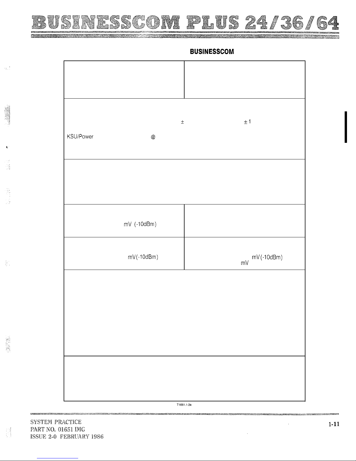
Table H-3 SPECIFICATIONS, PLUS 64
GENERAL SPECIFICATIONS
System Capacity: MAX. NO.
CO Lines 24
Intercom Talkpaths
Stations
6
64
ELECTRICAL SPECIFICATIONS
Power Requirements: (AC Supply Must Be Dedicated)
KSU/Power Supply Operating Range: 117 VAC
Power Dissipation:
Supply Unit: 870 Watts 7.4 Amps
Grounding Requirements:
KSU Ground lug, 14 AWG or larger copper wire to cold water pipe or known good earth ground
Cable Requirements:
Four conductor (two-pair twisted) station wire. 1000 feet (304.8 m) using 24 AWG. 1500 feet (457.2
m) using 22 AWG.
Door Chime Box: 500 feet (152.4 m) using 24 AWG.
Console: 1000 feet (304.8) using 24 AWG or 500 feet (152.4 m) if two consoles are used and one
is used as a BLF (Busy Lamp Field)
System Capacity:
Speakerphones
OPX Telephones
10%
60 Hz Hz
2968 BTU/HI=.
MAX. NO.
24
32
Background Music Specifications:
Input Impedance: 600 OHMS
Input Level: Nominal 250
Maximum Input: 1 Volt RMS
Music On Hold Specifications:
Input Impedance: 600 OHMS
Input Level: Nominal 250
Maximum Input: 1 Volt RMS
MECHANICAL SPECIFICATIONS
Dimensions and Weights:
KSU: 27.8 in.
x 26.1 in. x 8.5 in.
713.0 mm x 670.0 mm x 219.0 mm
Power Supply: 13.3 in.
x 19.0 in. x 4.8 in.
340.0 mm x 488.5 mm x 122.0 mm
Executive/Key Telephone: 3.1 in.
80.0 mm
Door Chime Box:
5.1 in.
x 8.0 in. x 8.6 in.
x 205.0 mm x 221.0 mm
x 3.9 in. x 1.4 in.
131 .O mm x 99.0 mm x 35.0 mm
DSS Console: 2.0 in.
52.0 mm
x 7.4 in. x 8.8 in.
x 189.0 mm x 224.0 mm
ENVIRONMENTAL SPECIFICATIONS
Environmental Operating Conditions:
Temperature:
KSU and Telephones: 0 to 45 degrees C
Door Chime Box: -20 to 60 degrees C
Humidity: 10% to 95% noncondensing
Limit for Alarm Circuit:
Loop Resistance: 1000 OHMS Max.
External Paging Specifications:
Output Impedance: 600 OHMS
Output Level: Nominal 250
Maximum Output: 400 RMS
81.6 Ibs.
37.0 kg
19.4 Ibs.
8.8 kg
2.2 Ibs.
1.0 kg
0.4 Ibs.
0.2 kg
1.3 Ibs.
0.6 kg
(32 to 113 degrees F)
( -4 to 140 degrees F)
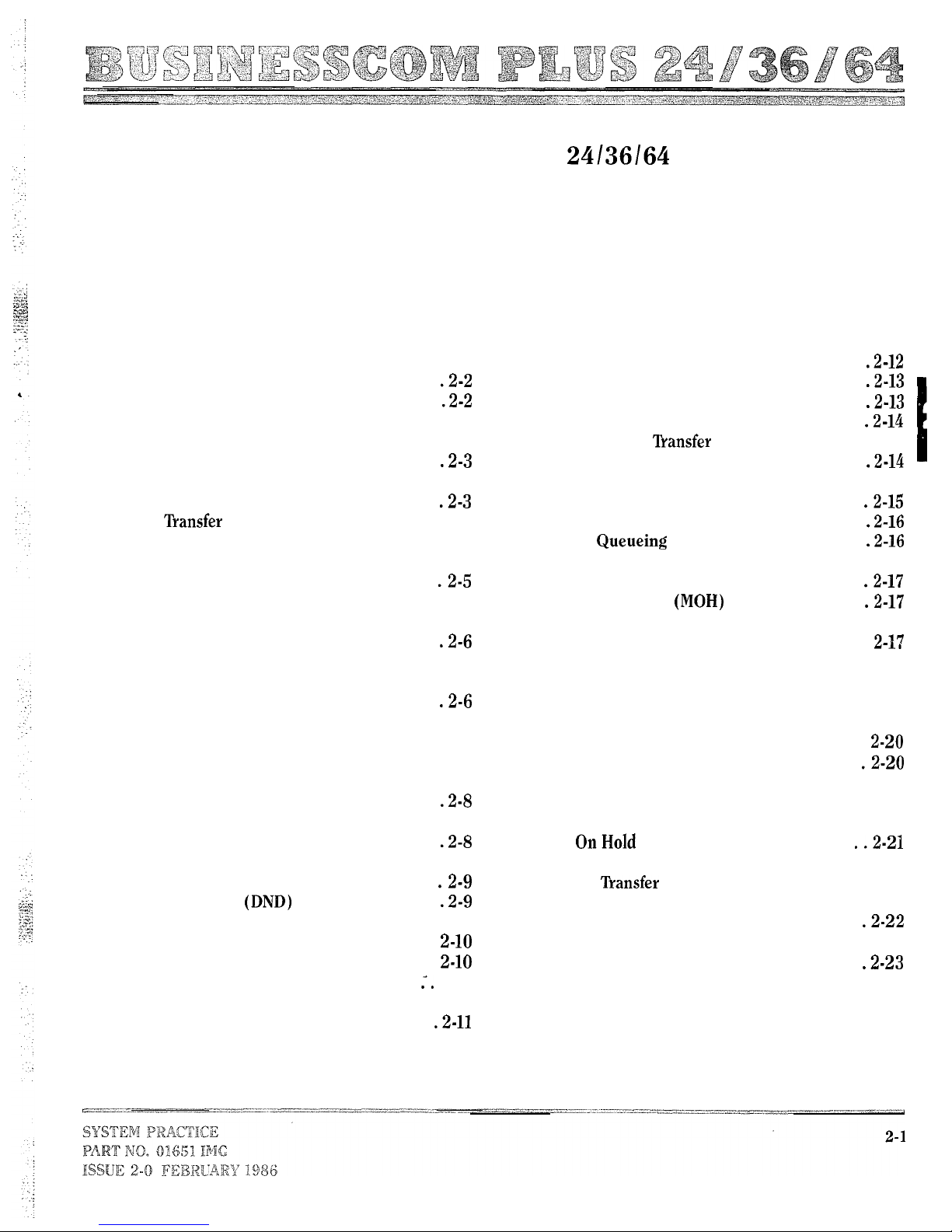
BUSINESSCOM PLUS
ELECTRONIC KEYTELEPHONESYSTEMS
SECTION 2,FEWTURES
CONTENTS PAGE CONTENTS
1.
INTRODUCTION ..................... 2-2
2. DESCRIPTION. .....................
Automatic Intercom Answer. ..........
Background Music (BGM) ............. 2-2
Call Duration Timer ................. 2-2
Call Forward With Follow-Me. .........
Call Monitor ....................... 2-3
Call Pickup. ......................
Call Announced .............. 2-4
Call Transfer Unannounced ............ 2-4
Call Waiting ....................... 2-4
Callback .........................
Camp-On ......................... 2-5
CO Lines ..........................
Common Use Line. .................
Component Commonality ............. 2-6
Conference, Add-On ................. 2-6
Conference, Meet-Me ................
Conference, Multi-Line ............... 2-7
Conference, Unsupervised ............. 2-7
Confirmation Tone
Dial Pulse To Tone (DTMF)
Conversion. .....................
Direct Inward System Access (DISA) ..... 2-8
Direct Station Selection (DSS) .........
Direct Station Selection (DSS)
Console ........................
Do Not Disturb ...............
Do Not Disturb (DND) Override
By DSS Console ..................
Door Chime Box ...................
Dual Handsfree Hotline
Excluded System Features ............
Executive Call Forward. .............
Executive Override (Barge In) .........
External Alarm Signals To
Stations ........................
..................
............
2-5
2-8
2-10
2-11
2-12
2-12
PAGE
Flash. ..........................
Flexible Line Appearance. ...........
Flexible Station No. Assignment. ......
Group Hunt. .....................
Group Hunt ................
Handsfree Reply On Intercom. ........
Hold ............................
Intercom. .......................
Last Number Dial. .................
Line ....................
Message Waiting ...................
Microphone On/Off ................
Music On Hold ..............
Night Class Of Service ...............
Night Transfer .....................
Off-Premises Extension ..............
Paging, All Call ....................
Paging, All External Zone ............
Paging, External Zone ...............
Paging, Internal Zone ...............
Paging, Meet-Me. .................
Private Line ...................... 2-20
Recall Line Preference ...............
Release Of Abandoned Calls
......................
Remote Busy Line Indication .......... 2-21
Ring
Ringing Line Preference ............. 2-22
Room Monitor. ...................
Save
............................ 2-23
Single Step Access. ................
Speed Dial ....................... 2-23
Step Calling ...................... 2-24
Tenant Service.................... 2-24
Three Minute Warning Tone .......... 2-24
Toll Restriction .................... 2-25
Transfer Recall Display .............. 2-25
..................... 2-22
2-14
2-15
2-16
2-17
2-18
2-19
2-19
2-19
2-21
1.
INTRODUCTION
BACKGROUND MUSIC (BGM)
1.01
This section lists and details the features available
in the Businesscorn Plus Both
permanent and programmable features are discussed. This
Description:
This feature permits station speakers and external zones to
receive Background Music.
section should be used in conjunction with Section 4,
SOFTWARE CONFIGURATION, when preparing the
Program Record Form.
Conditions:
(a) BGM is a customer supplied item.
(b) BGM can serve as a source of Music On Hold.
(c) BGM is interrupted at a zone and/or station by an
incoming call, and at a station by an outgoing call.
2.
DESCRIPTION
(d) BGM is interrupted at stations utilizing Room Monitor.
(e) BGM utilizes one Intercom link.
2.01 This section is formatted in the following manner:
Basic Programming:
Description:
Conditions:
discusses the basic elements of the feature.
lists and describes conditions that limit or
enhance the feature under discussion.
Basic Programming:
lists required programming, i.e.,
programming necessary for feature operation.
Program 26-Background Music
Related Programming:
Program l&External Paging Output
Feature Interactions:
CO Lines
Hold
Programming:
feature operation.
lists programs that limit or enhance
Intercom
Music On Hold (MOH)
Room Monitor
Feature Interactions:
lists features that directly affect the
feature under discussion.
CALL DURATION TIMER
AUTOMATIC INTERCOM ANSWER
Description:
This feature permits a user to time the duration of an
Description:
outgoing CO call.
This feature permits single-step answer of an internal call.
Conditions:
Conditions:
None
(a) This feature is available only on Executive Display
telephones.
Basic Programming:
None
(b) The timer starts from 0 to 255 seconds after CO line
seizure depending upon programming.
Related Programming:
None
(c) This feature can be manually started.
(d) If a Hold is implemented during a CO call, the timer is
Feature Interactions:
disabled and the display returns to its normal condition.
Intercom

Basic Programming:
Program Duration Timer
Related Programming:
Program Duration Start Timer
CALL MONITOR
Description:
This feature permits the on-hook dialing of an Intercom or
CO telephone number.
Feature Interactions:
CO Lines
Hold
Conditions:
(a) Telephones without speakerphones must lift the handset
to engage in a two-way conversation once the call is
established.
(b) The user can also monitor a CO call if placed on Hold.
CALL FORWARD FOLLOW-ME
Basic Programming:
Description:
This feature permits the automatic transfer of an incoming
Related Programming:
Intercom call to a second station (Call Forward). The
destination of the forwarded call can be changed to yet a third
station and so on (Follow-Me).
Feature Interactions:
CO Lines
Intercom
Conditions:
(a) The originating station can change the destination of the
Call Forward.
CALL PICKUP
(b) Only the originating station can cancel a Call Forward.
(c) The destination station can change the destination of the
Follow-Me.
(d) Program 49 (Excluded System Features) can disable this
Description:
This feature permits a station user to intercept an Intercom
call intended for another station.
feature.
(e) A call cannot be forwarded to a station that has invoked
DND.
(f) Executive Call Forward overrides Call Forward With
Conditions:
(a) Program 49 (Excluded System Features) can disable this
feature.
Follow-Me.
Basic Programming:
Basic Programming:
Related Programming:
None
Related Programming:
Program 49-Excluded System Features
Program 49-Excluded System Features
Feature Interactions:
Feature Interactions:
Intercom
CO Lines
Executive Call Forward
Intercom
None
None
None
2-3
CALL TRANSFER ANNOUNCED
Description:
feature permits the voice announced transfer of an
This
established CO call.
:
Voice Announce must be programmed.
Program 49 (Excluded System Features) can disable this
feature.
If the transferred call is not answered within a
programmed period of time, the call reverts back to the
transferring station.
This feature is accessible from a key telephone or DSS
Console.
Basic Programming:
Program 24-Voice Announce /Tone Signal Call
Related Programming:
Program Console Port Assignment
Program
Program 39-DSS Transfer Timer
Program 49-Excluded System Features
Feature Interactions:
CO Lines
Direct Station Selection (DSS) Console
Intercom
CALL TRANSFER UNANNOUNCED
Description:
This feature permits the transfer of an established CO call,
with ringing, to a second station.
Conditions:
(a) If the transferred call is not answered within a
programmed period of time, the call reverts back to the
transferring station.
(b) Program 49 (Excluded System Features) can disable this
feature.
(c) This feature is accessible from a key telephone or a DSS
Console.
(d) Tone Signal must be programmed.
Transfer Timer
Related Programming:
Program Console Port Assignment
Program
Program 39-DSS
Program 49-Excluded System Features
Feature Interactions:
CO Lines
Direct Station Selection (DSS) Console
CALL WAITING
Description:
This feature permits two types of Call Waiting:
(a) CO Call Waiting.
Intercom Call Waiting.
CO Call Waiting allows a station with a seized CO line to
receive ringing for another incoming call on another line.
Intercom Call Waiting allows a station with a seized Intercom
link to receive ringing for another incoming Intercom call.
Conditions:
Intercom Call Waiting is unavailable at stations using
Handsfree Reply On Intercom.
‘Iwo levels of Intercom Call Waiting are available through
programming:
(1) User-controlled: allows user to initiate the Call
Waiting signal.
(2) Automatic: the Call Waiting signal is automatically
initiated.
Callback and Camp-On are unavailable when the
automatic mode of Intercom Call Waiting is in use.
Call Waiting (CO) signals are blocked by all levels of Do
Not Disturb when Do Not Disturb is in use. Intercom Call
Waiting signals are blocked by Do Not Disturb (level 2
and level 3 where LED lights steadily) when Do Not
Disturb is in use.
This feature is permanent for Intercom calls with respect
to the DSS Console, i.e., the DSS Console has
permanent override capabilities.
Basic Programming:
Program 16-CO Call Waiting
Program 23-Intercom Call Waiting
Timer
Timer
Basic Programming:
Program Announce /Signal Tone Call
Related Programming ,
Program Console Port Assignment
Feature Interactions:
Basic Programming:
CO Lines
Direct Station Selection (DSS) Console
Do Not Disturb (DND)
Related Programming:
Program 49-Excluded System Features
Handsfree Reply On Intercom
Intercom
Feature Interactions:
Call Waiting Intercom
Intercom
CALLBACK
CO
Description:
LINES
This feature permits a station to receive a signal tone when
a previously called busy station resumes an idle condition. If
the caller seizes the Intercom link after the signal tone, the
idle station is automatically called.
Description:
This feature permits the formation of CO line groups with the
option of outgoing and/or incoming access and incoming
audible assignment. Lines can be grouped and identified as
Conditions:
follows:
(a) The link must be seized within 20 seconds after the
initiation of the Callback signal or the recall is dropped.
(b) Camp-On requests have priority over Callback requests.
(c) Callback cannot be used if the automatic mode of
Intercom Call Waiting is programmed.
Basic Programming:
Related Programming:
Feature Interactions:
None
None
Call Waiting Intercom
Camp-On
Intercom
Conditions:
Thirty groups are permitted.
Each group can contain as many consecutive lines as
required.
Each line can be programmed for either Dial Pulse or
DTMF signaling.
Stations assigned line groups with day audible receive
audible when Night Transfer is not activated. Stations
assigned line groups with night audible receive audible
when Night Transfer is activated.
assignable on a per station basis.
assignable on a per station basis.
CAMP-ON
Description:
This feature permits a calling station to wait off-hook for a
busy station to resume an idle condition. At this point the idle
station is automatically recalled.
Class of Service and Night Class of Service can be used
to prohibit or limit outgoing access.
Audible tone rate is programmable.
Basic Programming:
Program l-Line Dial Mode, CO Queueing Group
Program 2-CO Line Group Assignments
None
CO line groups providing incoming access are
CO line groups providing outgoing access are
Conditions:
Camp-On is unavailable if the automatic mode of
Intercom Call Waiting is programmed.
Program 49 (Excluded System Features) can disable this
feature.
Camp-On requests have priority over Callback requests.
Camp-On utilizes an Intercom link when in use.
Related Programming:
Program 6-CO Line Outward Access Assignment
Program 7-CO Line Incoming/Audible Assignment
Program
Program Audible Rate Assignment
Program
Audible Rate Assignment Timer
Feature Interactions:
Basic Programming:
Night Class of Service
Night Transfer
Toll Restriction
Related Programming:
Program Line Appearance
Program Line Preference
Program 47-Recall Line Preference
COMMON USE LINE
Feature Interactions:
Description:
This feature permits a CO line to be accessible by any station
but subject to that station’s Class of Service. It allows both
incoming and outgoing access.
Flexible Line Appearance
Line Queueing
Recall Line Preference
Ringing Line Preference
None
Conditions:
(a) Any line can be used as a Common Use Line.
(b) Access to a Common Use Line can be limited by
Flexible Line Appearance is a feature that “‘shifts” lines to
different line keys. See Flexible Line Appearance for further
explanation.
telephone instrument type.
(c) Common Use Lines are unavailable when Flexible Line
Appearance is programmed.
Basic Programming:
Program 3-Common Use Line
Related Programming:
Feature Interactions:
None
Flexible Line Appearance
COMPONENT COMMONALITY
Description:
This feature permits the use of different system components
in a single system (e.g., any telephone in the Businesscorn
Plus Family can be used in any Businesscorn Plus System).
CONFERENCE, ADD-ON
Description:
This feature permits internal parties to Conference with each
other.
Conditions:
(a) Six internal parties can enter the Conference.
(b) Program 49 (Excluded System Features) can disable this
feature.
Basic Programming:
Related Programming:
Program 49 Excluded System Features
Feature Interactions:
Intercom
None
Conditions:
If there are more lines assigned to a telephone than line
keys available to accommodate them, a phantom ring can
occur For example, if line five has an incoming call and
a Businesscorn Plus 3 Line telephone is programmed
incoming access and audible for that line, the callrings
in but no line key The call can still be
answered by lifting the handset or pressing the SPK key
provided that Ringing Line Preference is programmed.
A station can queue for a CO line that it has access to,
but no line appearance for, if Recall Line Preference
(Program 47) is programmed.
2-6
CONFERENCE, MEET-ME
Description:
This feature permits selected stations to Conference with a
Paging station.
Conditions:
(a) Five stations can Conference with the page initiator.
(b) The initiating station can use Internal Zone Paging or
All Call Paging to initiate this feature.
(c) If Internal Zone Paging is used, only those stations
CONFERENCE, UNSUPERVISED
granted assignment to that Paging group are allowed to
Conference.
(d) Only those stations programmed assignment to a Paging
group are permitted to join in a Meet-Me Conference,
regardless of the Paging feature used to initiate the
Description:
This feature permits an internal party to establish a
Conference between external parties wherein the Conference
is maintained after the initiating party hangs up.
Conference.
(e) Program 49 (Excluded System Features) can disable this
Conditions:
feature.
When Meet-Me Conference is initiated, the zone is made
(f)
unavailable to others in the system for a period of 30
seconds or until five stations enter the Conference.
Conference.
Multi-Line Conference and Release of Abandoned Calls
on Hold must be programmed for Unsupervised
Conference to function.
Basic Programming:
Program Groups
The following station ports must be available, i.e., station
card installed, but unterminated:
Related Programming:
Program 49-Excluded System Features
Feature Interactions:
Paging, All Call
Paging, Internal Zone
Lines used for Unsupervised Conference must utilize
open loop disconnect supervision,
The Conference initiating party can reenter the
Conference.
CONFERENCE, MULTI-LINE
Description:
This feature permits internal parties to Conference with more
than one external party.
Conditions:
Six internal parties can Conference with two external
parties.
Stations programmed for Executive Override can enter
a Multi-Line Conference uninvited provided that the total
number of stations in the Conference does not exceed
six.
Basic Programming:
Program 30-Multi-Line Conference
A 600 OHM resistor must be connected across the
unsupervised station position. See Section 5, INSTALL
more information.
Basic Programming:
Program &Unsupervised Conference
Program 30-Multi-Line Conference
Program 54-Release of Abandoned Calls on Hold
Related Programming:
Feature Interactions:
CO Lines
Conference, Multi-Line
Release of Abandoned Calls On Hold
external parties can engage in Unsupervised
System Port
24 18
36
64
22
34
(Station Cabling and System Connections) for
None
Related Programming:
None
Feature Interactions:
CO Lines
Executive Override (Barge In)
Intercom

 Loading...