

Tidland Maxcess 650 Series, Maxcess 650HD Series, Maxcess 750 Series User Manual
Tidland Leaf Shaft
User Manual
EN
Series 650/650HD/750
MI 27L691995 1 L
TIDLAND WINDING SOLUTIONS

www.maxcessintl.com
Tidland Leaf Shaft
MI 27L691995 1 L
Page 2
IMPORTANT SAFETY INSTRUCTIONS
When using this Tidland product, basic safety precautions should always be followed to reduce the
risk of personal injury. Your company's safety instructions and procedures should always be followed.
When using this product with any other equipment or machinery, all safety requirements stipulated by
that equipment or machinery manufacturer must be followed. Compliance with local, state, and federal
safety requirements is your responsibility. No part of these or the following instructions should be
construed as conflicting with or nullifying the instructions from other sources. Be familiar with the
hazards and safety requirements in your work environment and always work safely.
Read and understand all instructions and shaft design application limits before operation.
Never use this product for a purpose or in a machine that it was not specifically designed for. See
Product Safety Data Sheet (PSDS).
Do not exceed the operation loads for this shaft as noted on its PSDS, Product Safety Data Sheet.
Follow all warnings and instructions marked on the product and on the PSDS.
Do not use fingers or other objects to deflate the shaft; Tidland recommends using the Tidland Air
Release Tool (see page 3).
Inspect the shaft for wear and/or other safety and functional deficiencies daily, before each use.
Wear safety glasses or proper eye protection when inflating or deflating or otherwise operating the air
system.
Do not remove or otherwise alter any setscrews or fastening devices prior to using this product.
Do not operate this product if any setscrews or fastening devices are missing.
Do not lift shaft manually if it is beyond your capacity. Loads over 1/3 your body weight may be
prohibitive. Consult your company safety policy.
When lifting a shaft, use proper lifting techniques, keeping back straight and lifting with the legs.
Do not carry or lift this product over wet or slippery surfaces.
Use appropriate mechanical lifting devices, such as a hoist or shaft puller, for heavier shafts.
When performing maintenance or repair procedures, do not pressurize the shaft if journal setscrews
are loose or missing.
When performing maintenance procedures, do not pressurize the shaft if the journal is missing.
All replacement parts used on this product should be made to original Tidland specifications.
All maintenance and repair procedures performed on this product should be done to Tidland
specifications by qualified personnel.

www.maxcessintl.com
Tidland Leaf Shaft
MI 27L691995 1 L
Page 3
TABLE OF CONTENTS
Important Safety Information ................................................................................................................... 2
Assembly Diagram and Parts .................................................................................................................. 4
Shaft Installation and Operation .............................................................................................................. 5
Standard Leaf Shaft ............................................................................................................................ 5
Fixed Leaf Shaft .................................................................................................................................. 5
Coreless Gripper Leaf Shaft ................................................................................................................ 5
Maintenance ............................................................................................................................................ 6
Replacing a Valve ............................................................................................................................... 6
Rubber Tube Fitting Designs .............................................................................................................. 7
Using the hose clamp with bulk rubber tube material ..................................................................... 8
Rubber Tube Maintenance .................................................................................................................. 9
Removing the Rubber Tube Assembly ........................................................................................... 9
Installing the Complete Assembly ................................................................................................. 10
Disassembly .................................................................................................................................. 10
Reassembly .................................................................................................................................. 11
Shaft Assembly Sequence ................................................................................................................ 12
Torque Requirements ................................................................................................................... 12
Leaf Assembly ................................................................................................................................... 13
Replacing the Leaves ................................................................................................................... 14
Replacing Springs ......................................................................................................................... 14
Installing Add-on Leaves ................................................................................................................... 15
Troubleshooting ..................................................................................................................................... 16
CAUTION
Wear eye protection when using tools or compressed air.
CUSTOMER SERVICE
1.360.834.2345 www.maxcessintl.com
RECOMMENDED TOOLS
Clean, non-lubricated air supply: 80-120 psi (5.5-8.3 bar) for proper operation.
Tidland Inflation Tool (Part No. 27L128052)
Tidland Air Release Tool (Part No. 27L111630)
Pincers for removing hose clamps, if installed. See page 8.
LOCTITE
Dow Corning Molykote
®
222, 242
®
55 o-ring grease
MAINTENANCE SCHEDULE
Daily
Keep shaft clean and dry.
Remove dust and debris buildup with compressed air.
Periodically
Inspect journals for wear.
Check for bent external leaves.
www.maxcessintl.com
Tidland Leaf Shaft
MI 27L691995 1 L
Page 4
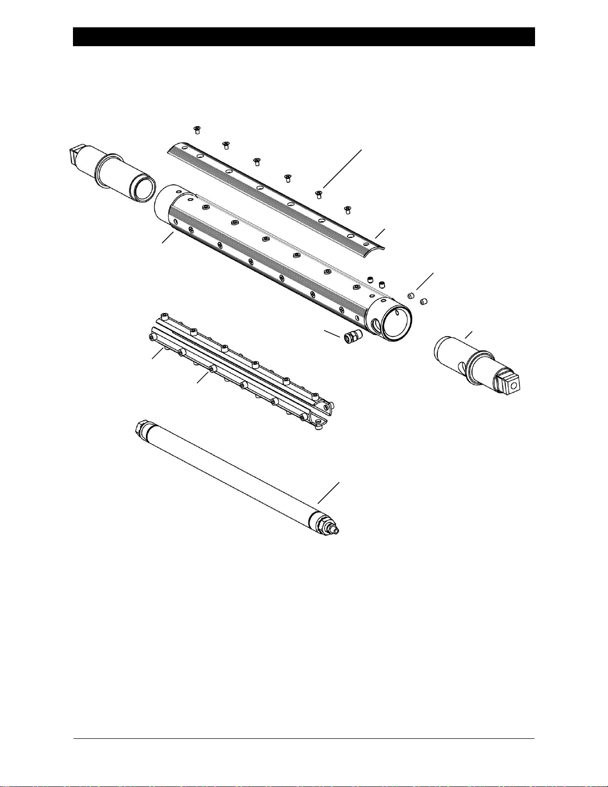
ASSEMBLY DIAGRAM AND PARTS
JOURNAL
EXTERNAL LEAF
LEAF SCREW
(ATTACHES EXTERNAL LEAF
TO INTERNAL LEAF BUTTONS)
NOTE:
Leaves on the 650HD shaft are not removable;
the screws are not accessible.
RUBBER TUBE ASSEMBLY
SEE PAGE
VALVE
(LOCATIONS VARY)
SHAFT BODY
JOURNAL SET SCREWS
(4 AT EACH END TYP)
(SHAFTS WITH END CAPS
INSTALLED USE ONE OR TWO
SET SCREWS)
INTERNAL LEAF SET
BUTTON
(CRIMPED ON)
Shaft configurations vary. When ordering replacement parts, please have your serial number ready.
See page 13 for end view of internal parts.
10-12 FOR DETAILS.
www.maxcessintl.com
Tidland Leaf Shaft
MI 27L691995 1 L
Page 5
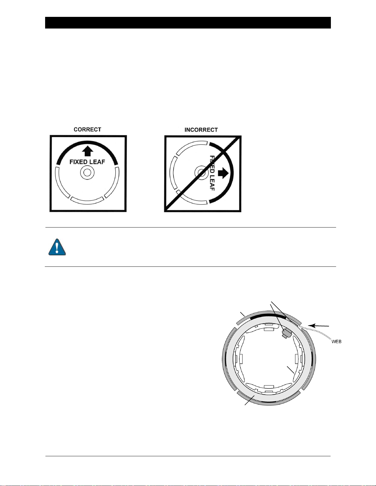
SHAFT INSTALLATION AND OPERATION
Positioning the fixed leaf at the top allows the internal rubber element to expand more
uniformly, and prevents the internal element from having to lift the weight of the material roll.
Inflating the shaft with the fixed leaf down or to the side can lead to
excessive element wear and premature failure.
INTERNAL LEAF
ASSEMBLY
FIXED LEAF
GRIPPER BAR
ASSEMBLY
SHAFT BODY
Standard Leaf Shaft
1. Install shaft as required for your machine application.
2. Slide the core onto the shaft.
3. Inflate rubber tube to 80-120 psi (5.5-8.3 bar) and begin winding.
Fixed Leaf Shaft
1. Install shaft as required for your machine application.
2. Rotate the shaft so that the fixed leaf is at the top; slide the core onto the shaft.
3. Inflate rubber tube to 80-120 psi (5.5-8.3 bar) and begin winding.
Coreless Gripper Leaf Shaft
1. Install shaft as required for your machine
application.
2. Make sure shaft is completely deflated.
3. Make sure fixed leaf is in the correct position.
4. Lay web along the length of the shaft, sliding
it into the gap between the fixed leaf and the
gripper bar.
5. Inflate rubber tube to 80-120 psi (5.5-8.3 bar),
securing the web between the leaves.
6. Begin winding operation.
 Loading...