

Tidland Performance Series, Class III, Class II, Class I User Manual
Performance Series
Manual Knifeholder
User Manual
EN
Class I, II and III
MI 557416 1 Q
TIDLAND SLITTING SOLUTIONS


KNIFEHOLDER SAFETY
HAND HAZARD.
all times.
IMPORTANT!
When using knifeholders, basic safety precautions should always be followed to reduce the risk of
personal injury. Your company's safety instructions and procedures should always be followed. When
using this product with any other equipment or machinery, all safety requirements stipulated by that
equipment or machinery manufacturer must be followed. Compliance with local, state, and federal
safety requirements is your responsibility. No part of these or the following instructions should be
construed as conflicting with or nullifying the instructions from other sources. Be familiar with the
hazards and safety requirements in your work environment and always work safely.
The knifeholder’s intended use is to produce a slit with a driven anvil system. There is no other
intended purpose.
Read and understand all instructions before operating the knifeholder. Failure to follow instructions
may cause the knifeholder to function incorrectly and can cause serious injury.
The knifeholder contains spring-loaded components. While operating the knifeholder, follow all
existing plant safety instructions and/or requirements.
Always wear stainless steel protective gloves when changing or removing the knife blade.
Sharp knives can cause serious injury. Do not put hands in machines. Compliance with federal,
state, and local safety regulations is your responsibility. Be familiar with them and always work
safely.
Inspect the knifeholder cartridge for wear and/or other safety and functional deficiencies daily,
before each use.
Do not carry or lift this product over wet or slippery surfaces.
All replacement parts used on this product should be made to original Tidland specifications.
All maintenance and repair procedures performed on this product should be done to Tidland
specifications by qualified personnel.
Keep clear. Keep
hands away from knife
blades at
Handle and unpack the equipment carefully. Upon arrival, check the shipment against the
packing list.
Promptly report to the carrier any damaged equipment.
Equipment not installed immediately should be stored in a clean, dry location.
Be careful to prevent moisture, dust, and dirt from accumulating in storage and installation areas.
Wear eye protection when using tools or compressed air.
www.maxcessintl.com Tidland Performance Series Manual Knifeholder MI 557416 1 Q Page 3
RECEIVING AND UNPACKING
CAUTION

CONTENTS
Receiving and Unpacking ........................................................................................................................ 3
Caution .................................................................................................................................................... 3
Knifeholder Components ..................................................................................................................... 6
Specifications ...................................................................................................................................... 6
Actuator Switch ................................................................................................................................... 7
Pneumatic 360° Blade Guard Cartridge .............................................................................................. 8
Class II – 548274 ............................................................................................................................ 8
Class III – 548275 ........................................................................................................................... 8
Extending the Blade Guard ................................................................................................................. 8
Flow Control Valve .......................................................................................................................... 8
Select Slitting Type ............................................................................................................................. 9
Recommended Knifeholder Setback (For Tangent Slitting Only) ....................................................... 9
Prepare to Mount Guide Bar ............................................................................................................. 10
Determine Space Requirements ................................................................................................... 10
Determine Mounting Dimensions .................................................................................................. 11
Install Guide Bar on Support Beam .................................................................................................. 12
Methods for Measuring Blade Overlap (For Reference Only) .......................................................... 12
Mount Knifeholder to Guide Bar ........................................................................................................ 13
Manual Lock .................................................................................................................................. 13
Pneumatic Lock ............................................................................................................................ 14
Easy Glider (Linear Bearing) ........................................................................................................ 15
Pneumatic System Requirements ..................................................................................................... 16
Operating Air Pressure ...................................................................................................................... 17
Down Force and Side Force ......................................................................................................... 17
Knifeholder ........................................................................................................................................ 18
Manual Lock .................................................................................................................................. 18
Pneumatic Lock ............................................................................................................................ 19
Cant Key ............................................................................................................................................ 20
Selection ....................................................................................................................................... 20
Orientation .................................................................................................................................... 20
Cant Key O-ring................................................................................................................................. 23
Replacing the O-ring ..................................................................................................................... 23
Blade Cartridge ................................................................................................................................. 23
Removing the Cartridge ................................................................................................................ 23
Reinstalling the Cartridge ............................................................................................................. 23
Reversing the Cartridge ................................................................................................................ 23
Knife Blade ........................................................................................................................................ 24
Removing the Blade ..................................................................................................................... 24
Replacing or Reinstalling the Blade .............................................................................................. 24
Blade Grinding and Finishing ........................................................................................................ 25
Slit Quality ......................................................................................................................................... 26
Knifeholder Performance .................................................................................................................. 27
Removing the Knifeholder from the Guide Bar ................................................................................. 29
Knifeholder Sub-Assembly Identification .......................................................................................... 30
Class I ........................................................................................................................................... 30
Class II and III ............................................................................................................................... 31
Guide Bar Mount Assembly – Class I, II, III ...................................................................................... 32
Manual Lock .................................................................................................................................. 32
Pneumatic Lock ............................................................................................................................ 33
Dovetail Assembly – Class III ............................................................................................................ 34
Upper Body and Piston Assemblies – Class I ................................................................................... 36
Lower Body Assembly – Class I........................................................................................................ 37
Upper Body, Lower Body and Piston Assemblies – Class II and III ................................................. 38
Class I ............................................................................................................................................... 40
Class II and III ................................................................................................................................... 41
Manual Control Body – Class I.......................................................................................................... 42
Manual Control Body – Class II and III ............................................................................................. 44
Manual Swing Cartridge – Class I ..................................................................................................... 46
Manual Swing Cartridge – Class II and III ......................................................................................... 48
Guide Bar Mount with Pneumatic Lock – Class I .............................................................................. 50
www.maxcessintl.com Tidland Performance Series Manual Knifeholder MI 557416 1 Q Page 4

CONTENTS
Guide Bar Mount with Pneumatic Lock – Class II and III .................................................................. 52
Guide Bar Mount with Manual Lock – Class I, II and III .................................................................... 54
Easy Glider Mount – Class I .............................................................................................................. 55
Easy Glider Mount – Class II and III ................................................................................................. 56
Performance Series and C Series – Class I, II and III ................................................................. 57
Tidland e-Knifeholder – Class II and III ........................................................................................ 57
www.maxcessintl.com Tidland Performance Series Manual Knifeholder MI 557416 1 Q Page 5
KNIFEHOLDER ORIENTATION
Note: Actual speed is dependent upon application and web material.
Class I
Class II
Class III
Blade Diameter
3.54" (90 mm)
5.91" (150 mm)
7.87" (200 mm)
Minimum Slit Width
1.0" (25.4 mm)
2.0" (50.8 mm)
3.0" (76.2 mm)
Designed Maximum Speed
3,500 fpm (1,067 mpm)
5,500 fpm (1,677 mpm)
10,000 fpm (3,049 mpm)
Recommended Operating
Air Pressure (max. 100 psi)
60-90 psi (4.1-6.2 bar)
60-90 psi (4.1-6.2 bar)
60-90 psi (4.1-6.2 bar)
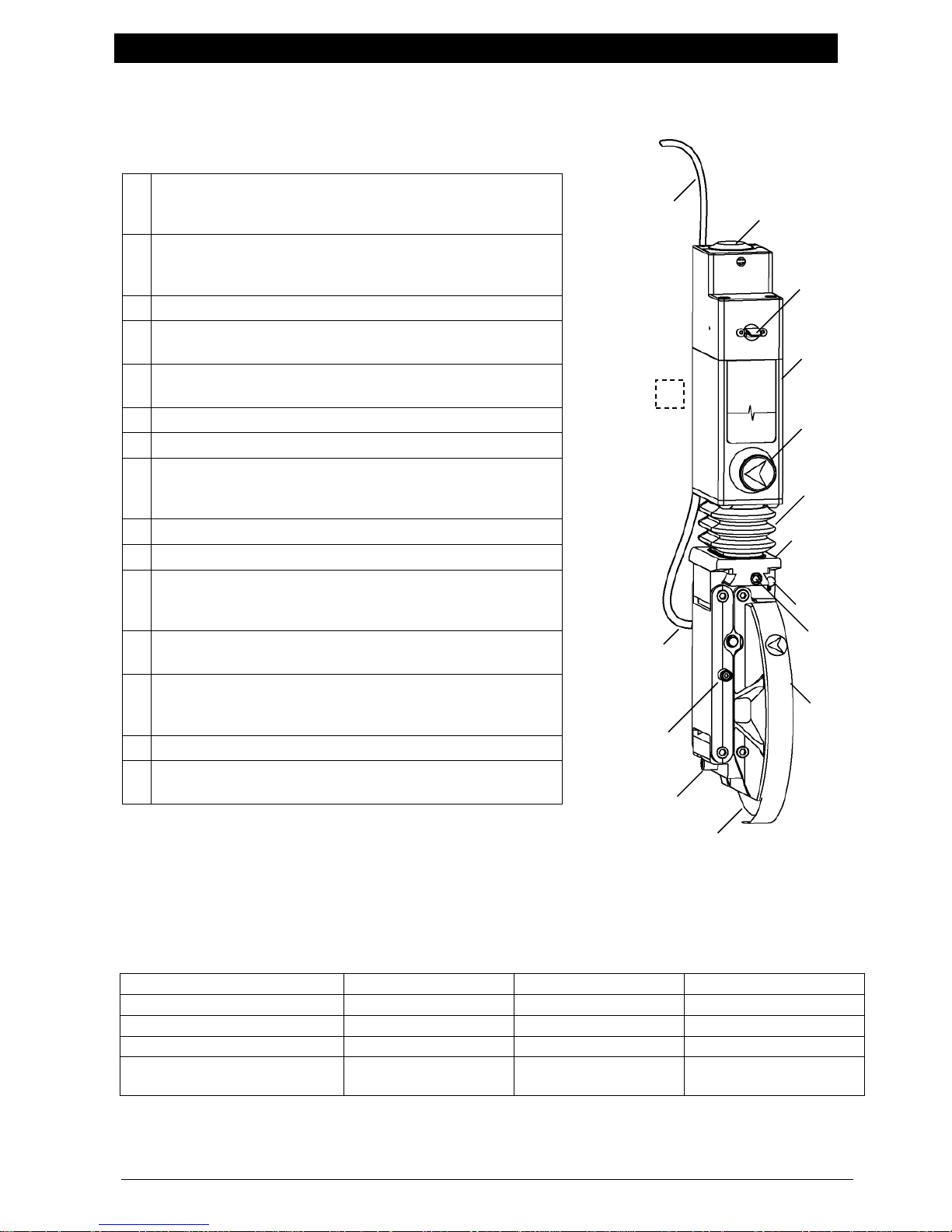
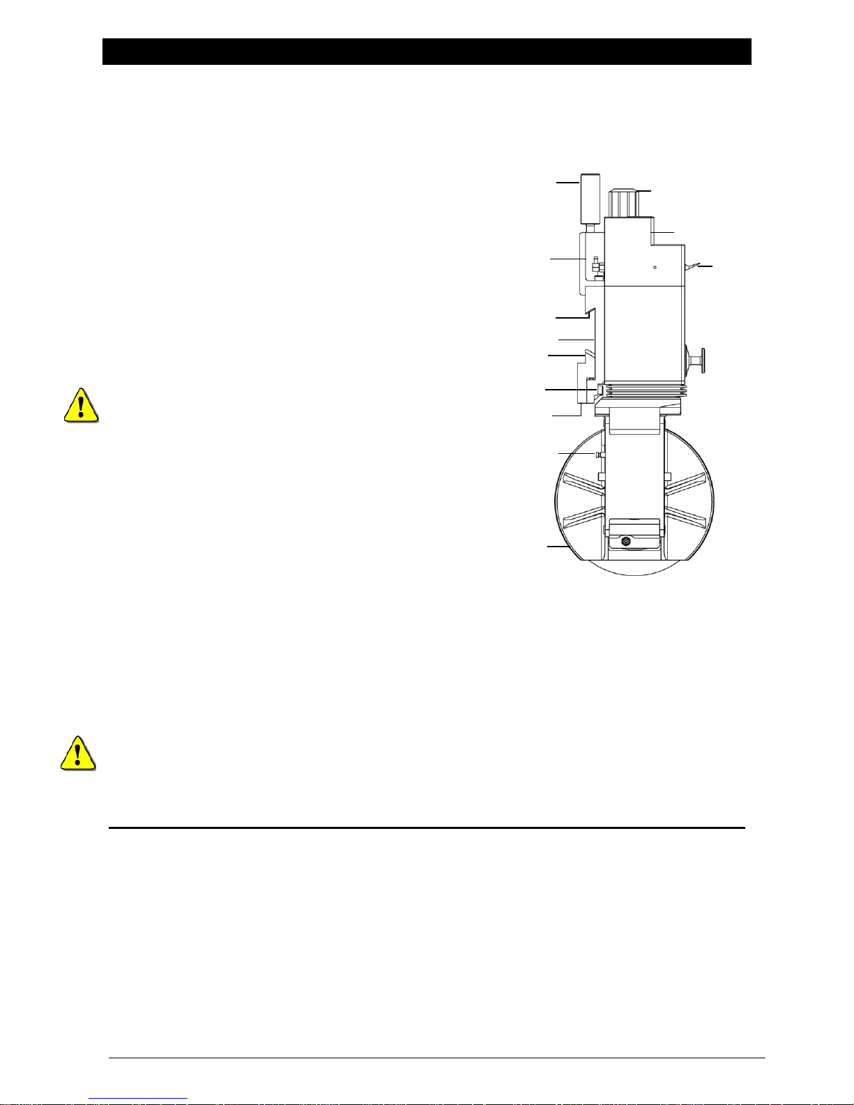
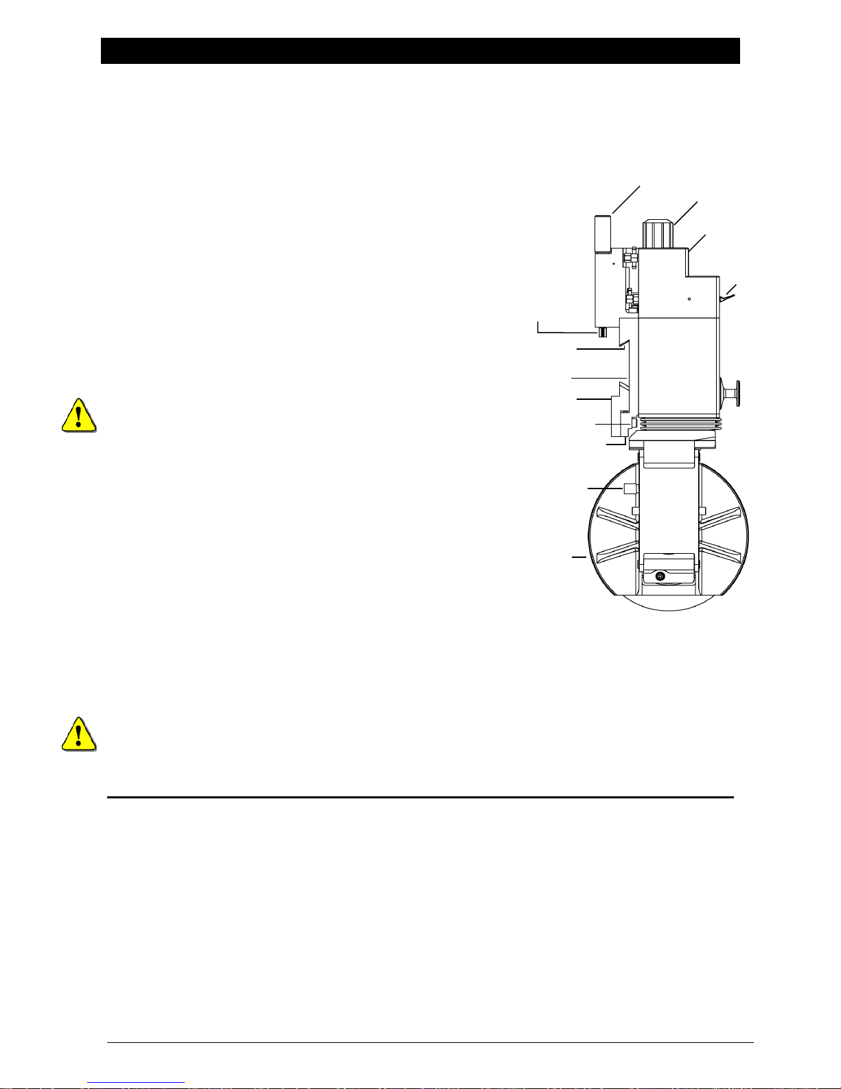
1
Depth Control Knob
Increase blade cartridge stroke – rotate counterclockwise
Decrease blade cartridge stroke – rotate clockwise
2
Actuator switch
Down – extends blade cartridge for setup or operation
Up – retracts blade cartridge
3
Knifeholder Control Body
4
Cant Angle Key
Blade cartridge angle control
5
Knifeholder Bellows
Prevents foreign matter from entering knifeholder
6
Dovetail (control body to blade cartridge interface)
7
Safety Lock Pin
8
Cartridge Lock Screw
Lock cartridge to control body – rotate clockwise
Unlock – rotate counterclockwise
9
Blade Cartridge (Blade Guard attachment not shown)
10
Knife Blade
11
Blade Lock Pin
Keeps shear blade from rotating. Use only when
removing or replacing the blade.
12
Setup Button
Use for knifeholder setup and positioning
13
Lower Hose Assembly with Quick Disconnect
Provides air supply to blade cartridge for side load
Allows removal of blade cartridge from the control body
14
Guide Bar Mount Assembly (not shown)
15
Upper Air Hose Assembly
Air supply for control body and blade cartridge
Knifeholder shown in extended position –
12
11
1
2
3 4 5
6
7
8
10
15
14
9
13
Knifeholder Components
Complete illustrations and part number begin on page 42.
Specifications
www.maxcessintl.com Tidland Performance Series Manual Knifeholder MI 557416 1 Q Page 6
air valve switch is down.
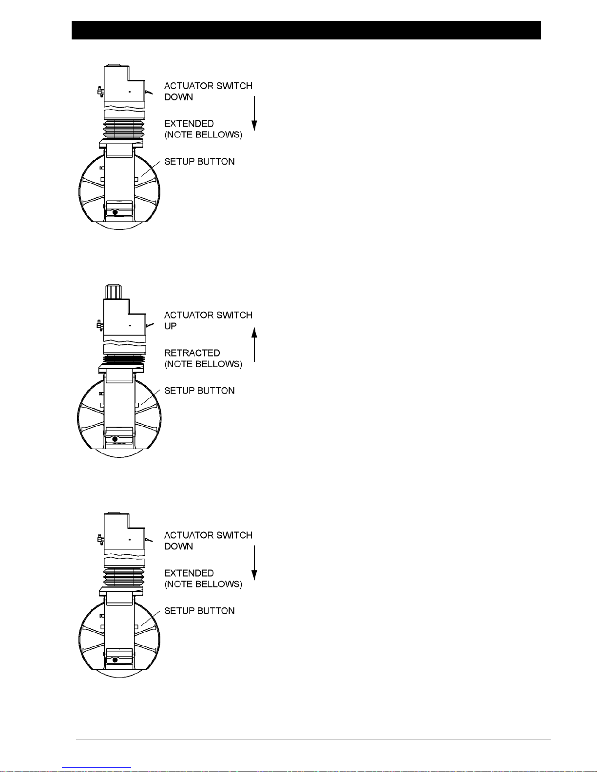
KNIFEHOLDER FUNCTIONS
Actuator Switch
– Sends air to the blade cartridge, extending the
knifeholder and providing side stroke.
– Use when positioning the knifeholder blade to the
anvil ring blade only when product machinery is not in
operation.
– Using the actuator switch with the setup button will
extend the knifeholder and provide half the side stroke
distance.
To position the knifeholder, see pages 18-19.
Switch UP (Retract)
– Reverses (returns) the blade cartridge side stroke
and then fully retracts the blade cartridge.
– Retract when:
the knifeholder is not in operation.
adjusting blade overlap with depth control knob.
traversing the knifeholder to slit positions.
Switch DOWN (Extend)
– Used with setup button, extends the blade cartridge
and then swings it at half side stroke.
– During operation, extends the blade cartridge and
then swings it at full side stroke.
www.maxcessintl.com Tidland Performance Series Manual Knifeholder MI 557416 1 Q Page 7
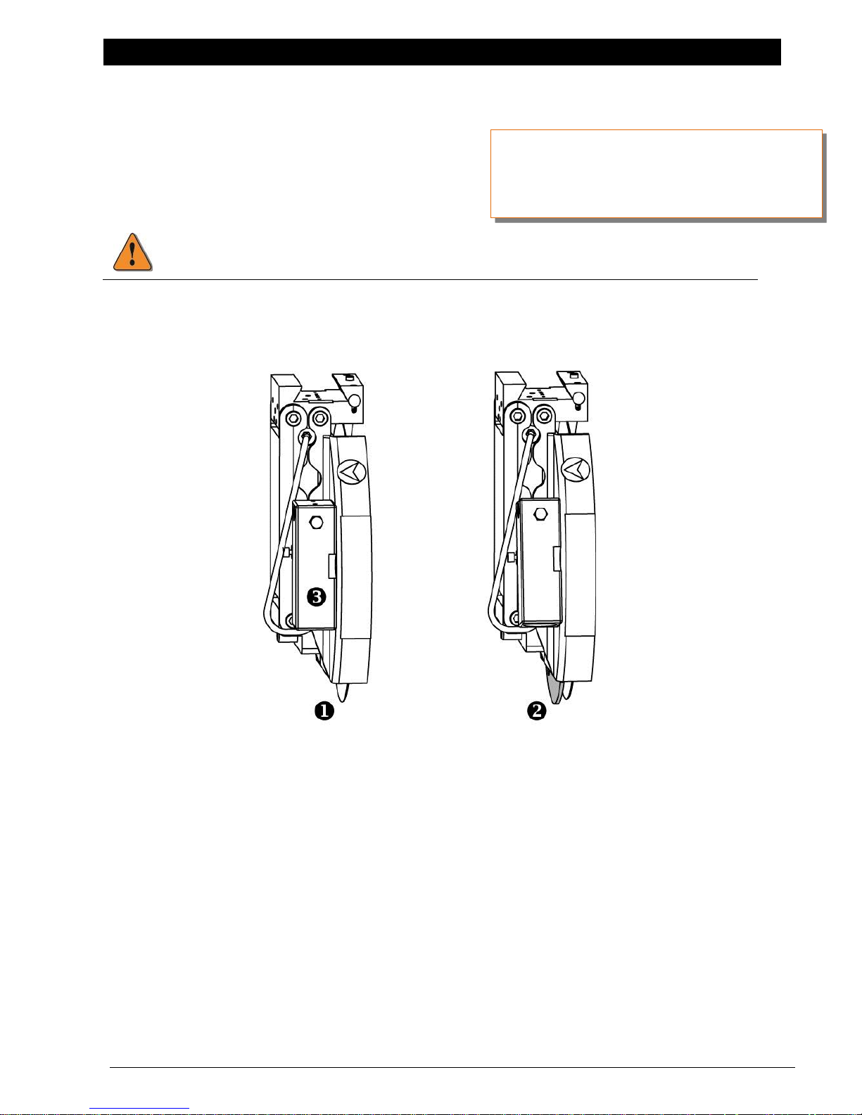
KNIFEHOLDER BLADE GUARD OPTIONS
This guard does not protect against bodily injury during handling and transport.
call Maxcess Customer Service.
Pneumatic 360° Blade Guard Cartridge
Class II – 548274
Class III – 548275
Shown in the unguarded (1) and guarded (2) positions.
For information about the mechanical
360° Blade Guard Cartridge,
Extending the Blade Guard
The blade guard is actuated automatically via an internal air circuit interface between the knifeholder
and the cartridge.
The cartridge extends and the blade guard retracts as the supply air is distributed at the setup knob in
either the GREEN (RUN) or YELLOW (SETUP) positions.
When the supply air is turned off at the setup knob RED (RETRACT) position, or at a gang manifold shut
off valve, the cartridge retracts and the blade guard extends out of the cartridge.
Flow Control Valve
The flow control valve assembly (3) provides a time delay between cartridge retraction and the blade
guard extension. Increase the delay by turning the flow control knob clockwise.
www.maxcessintl.com Tidland Performance Series Manual Knifeholder MI 557416 1 Q Page 8
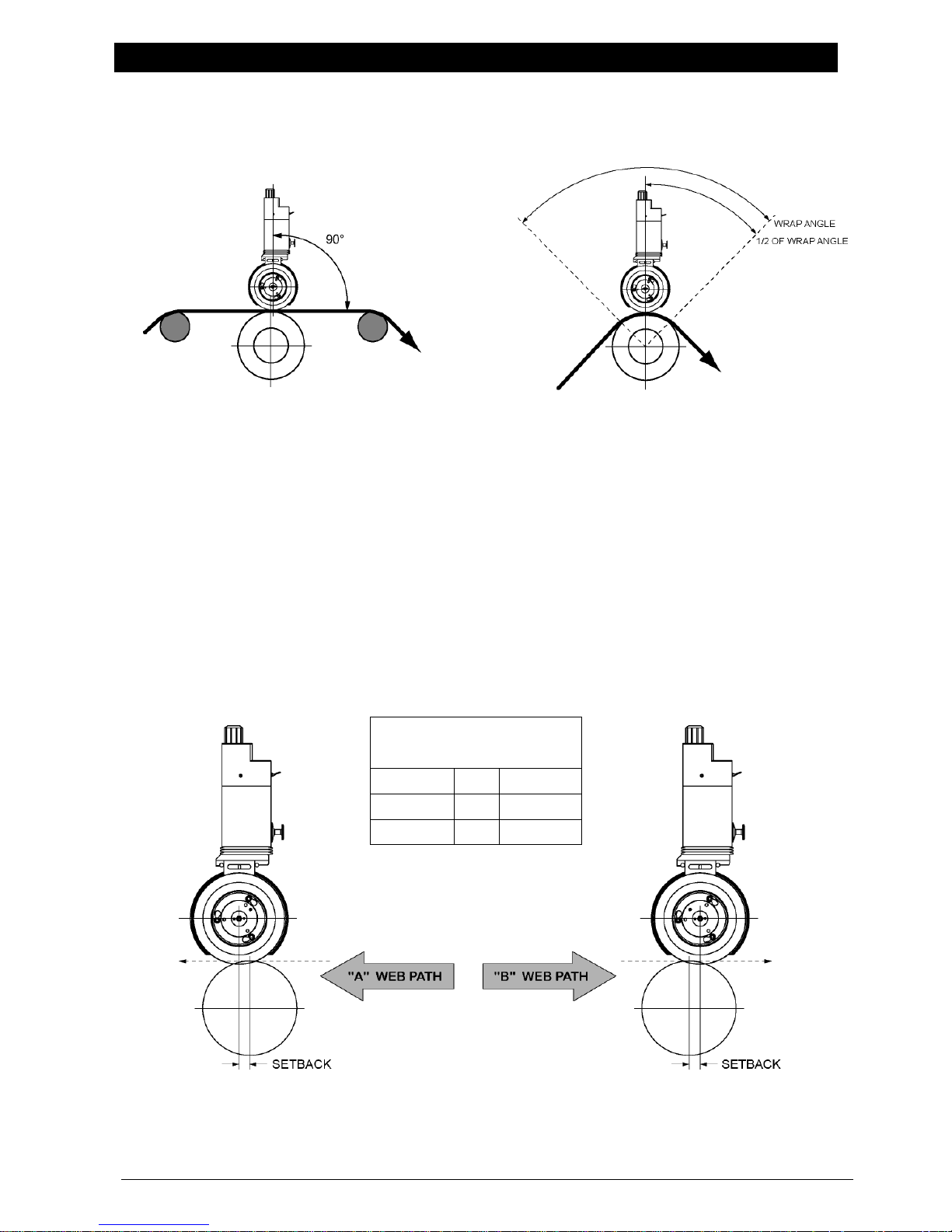
Select Slitting Type
TANGENT
WRAP
Knifeholder axis should be 90° to web path.
Tangent slitting requires knifeholder setback.
Knifeholder axis should bisect the wrap angle.
Knifeholder setback is not required.
Recommended Setback
for Paper Based Products
Class I
1/8"
3.18 mm
Class II
1/4"
6.35 mm
Class III
3/8"
9.53 mm
INSTALLATION
Recommended Knifeholder Setback (For Tangent Slitting Only)
For best slit result, the web must be in contact with the anvil knife ring at the cut point. If the web
contacts the top blade ahead of the cut point, the material will tear instead of slitting cleanly.
Geometry shown is based on medium weight kraft paper. For assistance with other web materials,
call Tidland Customer Service, 1-800-426-1000.
www.maxcessintl.com Tidland Performance Series Manual Knifeholder MI 557416 1 Q Page 9
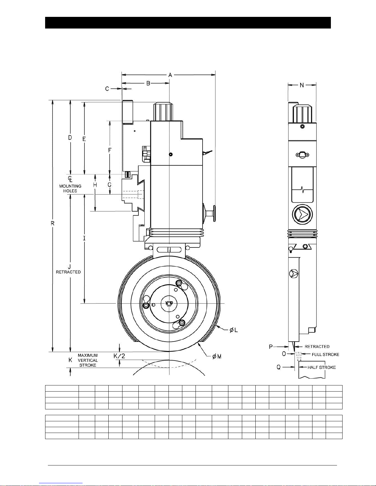
INSTALLATION
Inches
A B C D E F G H I J K L M N O P Q
R
Class I
4.74
2.46
0.05
3.86
3.61
2.89
1.04
1.84
4.85
6.62
0.63
3.92
3.54
0.945
0.12
0.19
0.05
11.51
Class II
5.72
2.95
0.03
4.55
4.41
3.26
1.28
2.34
6.79
9.74
1.00
6.33
5.91
1.75
0.16
0.38
0.08
15.57
Class III
6.47
3.46
0.04
4.73
4.56
3.05
1.28
2.34
7.83
11.77
1.00
8.35
7.87
2.76
0.24
0.77
0.12
17.78
Millimeters
A B C D E F G H I J K L M N O P Q R Class I
120.5
62.5
1.4
97.9
91.7
73.4
26.4
46.8
123.2
168.1
16.0
100
90
24.0
3.0
4.8
1.3
292.4
Class II
145.3
74.9
0.7
115.5
112
82.9
32.5
59.5
172.3
247.4
25.4
161
150
44.5
4.1
9.6
2.0
395.4
Class III
164.3
87.9
1.0
120
115.7
77.5
32.5
59.5
198.8
298.9
25.4
212
200
70.0
6.1
19.7
3.0
451.6
Prepare to Mount Guide Bar
Determine Space Requirements
www.maxcessintl.com Tidland Performance Series Manual Knifeholder MI 557416 1 Q Page 10
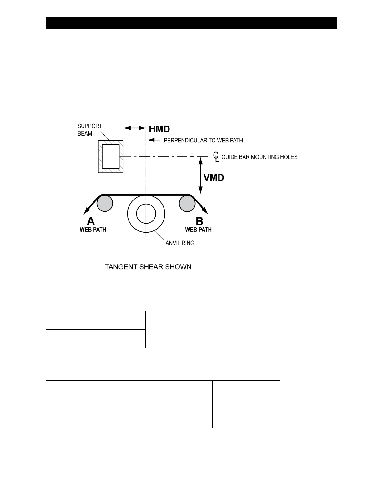
INSTALLATION
VMD (Vertical Mounting Dimension)
Tangent & Wrap Slitting
Class I
6-29/32"
(175.4 mm)
Class II
10-3/16"
(258.8 mm)
Class III
12-1/4"
(311.2 mm)
These dimensions reserve approximately 1/2 of blade cartridge stroke for blade regrinding.
HMD (Horizontal Mounting Dimension)
Tangent Slitting *
Wrap Slitting **
'A' Web Path
'B' Web Path
'A' or 'B' Web Path
Class I
2-9/16"
(65.1 mm)
2-5/16"
(58.7 mm)
2-7/16"
(61.9 mm)
Class II
3-7/32"
(81.8 mm)
2-23/32"
(69.1 mm)
2-31/32"
(75.4 mm)
Class III
3-27/32"
(97.6 mm)
3-3/32"
(78.6 mm)
3-15/32"
(88.1 mm)
* These dimensions will result in setbacks as listed in 'Recommended Setback Distance' on page 9.
** These dimensions provide no setback.
Determine Mounting Dimensions
Vertical Mounting Dimension – VMD
The distance from the centerline of the guide bar mounting holes to the anvil roll or ring O.D.
and perpendicular to the web path
Horizontal Mounting Dimension – HMD
The distance from the support beam face to the vertical centerline through the center of the anvil ring.
www.maxcessintl.com Tidland Performance Series Manual Knifeholder MI 557416 1 Q Page 11
INSTALLATION
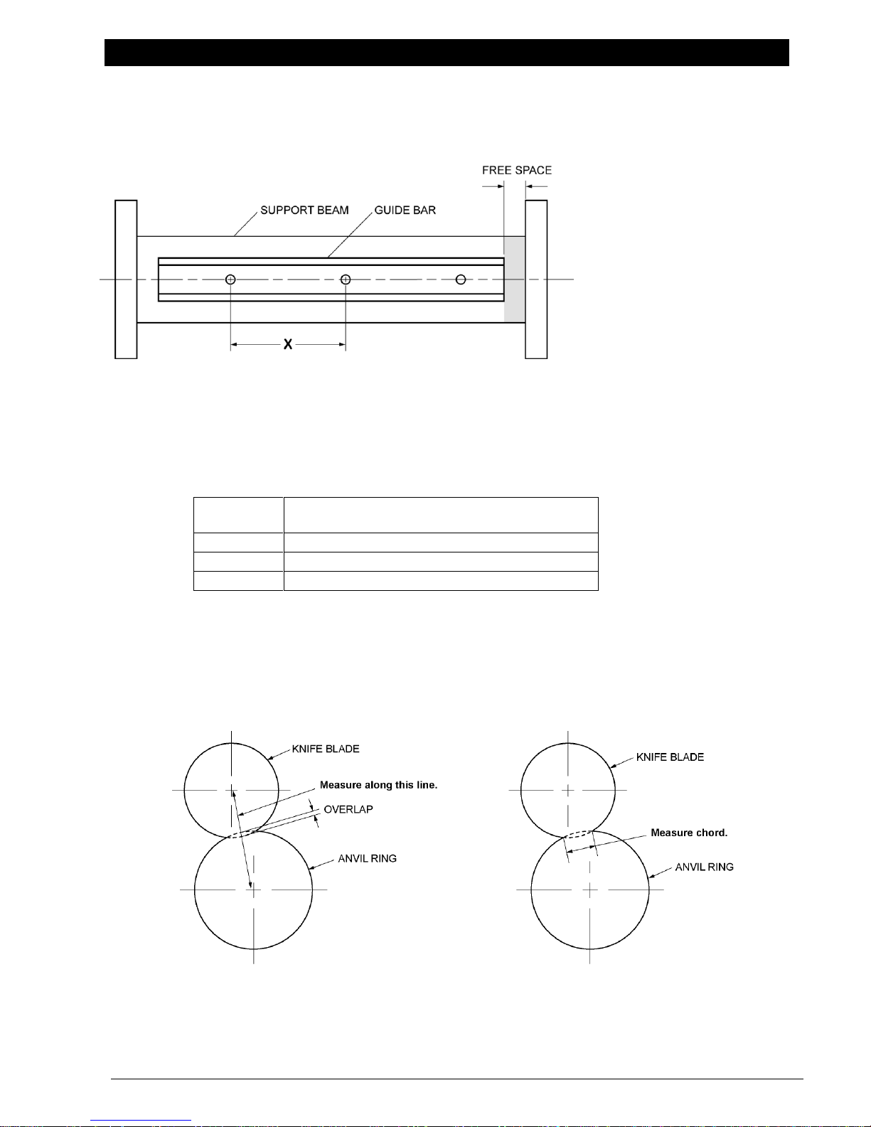
Minimum Space Recommended for Removal
(Free Space)
Class I
2" (50.8 mm)
Class II
3" (76.2 mm)
Class III
4" (101.6 mm)
Method 1
Measure blade overlap directly along the common
centerline of the knife blade and anvil ring.
Method 2
Measure the chord of the intersection between
the knife blade and anvil ring.
GUIDE BAR MOUNTING HOLES CENTERLINE
Install Guide Bar on Support Beam
The guide bar must be straight within 0.010” (0.25 mm) on a rigid and vibration-free support.
1. Determine the center-to-center distance between the mounting bolt holes (X) on the guide bar.
Standard pre-drilled dimension (X) is 12" (304.80 mm).
Drill and tap support beam for pre-drilled guide bar: 3/8"-16NC holes
2. Before transferring dimension (X) onto the support beam, make sure there will be enough free
space at one end of the beam for knifeholder installation and removal once the guide bar is mounted.
Methods for Measuring Blade Overlap (For Reference Only)
See pages 18-19 for knifeholder setup instructions.
www.maxcessintl.com Tidland Performance Series Manual Knifeholder MI 557416 1 Q Page 12
INSTALLATION
BRAKE KNOB
AIR SUPPLY INLET
GUIDE BAR MOUNT
GIB
GIB SOCKET HEAD
CAP SCREW
BRAKE SHOE
GIB SETSCREW
CONTROL
BODY
ACTUATOR
SWITCH
BLADE CARTRIDGE
AIR SUPPLY
DISCONNECT
DEPTH CONTROL
KNOB
BLADE
CARTRIDGE
Mount Knifeholder to Guide Bar
Manual Lock
Installation at End of Guide Bar (Recommended)
1. Turn the brake knob counterclockwise enough
to allow the brake shoe to be manually
retracted into the mount. (Push the brake
shoe up into mount if extended out.)
2. Align the mount with the guide bar end.
3. Slide the knifeholder onto guide bar. If
clearance is restricted, remove blade
cartridge (p. 23).
4. Adjust gib, if necessary. (See note below.)
5. Turn the brake knob clockwise to secure the
knifeholder in position.
6. Reinstall the blade cartridge onto the control
body, if removed (p. 23).
7. Toggle the actuator switch up before
connecting the air supply.
Installation at Center of Guide Bar
1. Remove blade cartridge from the control
body.
2. Remove the two socket head cap screws that
secure the gib to the mount.
3. Remove the gib.
4. Turn the brake knob counterclockwise to fully
retract the brake shoe into the mount. (Push the brake shoe up into mount if extended out.)
5. Place the control body onto the guide bar.
6. While holding the control body securely in place, reinstall the gib.
Align the gib socket head cap screw holes with the holes in the mount assembly.
7. Install and tighten the socket head cap screws to secure the gib in place.
Torque: Class I – 2.1 ft·lbs (2.85 Nm) Class II and III – 4.3 ft·lbs (5.83 Nm)
8. Adjust the gib, if necessary. (See note below.)
9. Turn the brake knob clockwise to secure the knifeholder in position.
10. Reinstall the blade cartridge onto the control body, if removed (p. 23).
11. Toggle the actuator switch up before connecting the air supply.
To Adjust Gib
1. Loosen the two gib socket head cap screws by 1/4 turn.
2. Tighten or loosen the gib set screw to achieve a secure fit and good knifeholder
traverse action on the guide bar. Recommended: ¼ turn per adjustment
3. Ensure that sides of gib are parallel to sides of knifeholder when adjusting
and tightening the two gib socket head cap screws.
Torque: Class I – 2.1 ft·lbs (2.85 Nm) Class II and III – 4.3 ft·lbs (5.83 Nm)
4. Readjust as necessary.
www.maxcessintl.com Tidland Performance Series Manual Knifeholder MI 557416 1 Q Page 13
INSTALLATION
BLADE
CARTRIDGE
AIR SUPPLY
DISCONNECT
GUIDE BAR
MOUNT
BRAKE SHOE
GIB
SOCKET HEAD
CAP SCREW
GIB SETSCREW
TRAVERSE/
BRAKE
KNOB
CONTROL
BODY
ACTUATOR
SWITCH
DEPTH CONTROL
KNOB
BLADE
CARTRIDGE
TRAVERSE
GEAR
Mount Knifeholder to Guide Bar
Pneumatic Lock
Installation at End of Guide Bar (Recommended)
1. Align the mount and traverse gear with the guide bar end
and gear rack.
2. Make sure the traverse/brake knob is in the unlocked (up)
position. (Push the brake shoe up into the mount if
extended out.)
3. Slide the knifeholder onto the guide bar. If clearance is
restricted, remove the blade cartridge (p. 23).
4. Turn the traverse knob to move the knifeholder into
position.
5. Adjust the gib, if necessary. (See note below.)
6. Push down the traverse/brake knob to lock the
knifeholder to the guide bar. Pull up the traverse/brake
knob to unlock and traverse the knifeholder.
7. Reinstall the blade cartridge onto the control body (p. 23),
if removed.
8. Toggle the actuator switch up before connecting the air
supply.
Installation at Center of Guide Bar
1. Remove the blade cartridge from the control body (p. 23).
2. Remove the two socket head cap screws that secure the
gib to the mount.
3. Remove the gib.
4. Place the control body onto the guide bar.
5. While holding the control body securely in place, reinstall
the gib and align the gib socket head cap screw holes
with the holes in the mount.
6. Install and tighten the socket head cap screws to secure the gib in place.
Torque: Class I ― 2.1 ft·lbs (2.85 Nm) Class II and III –– 4.3 ft·lbs (5.83 Nm)
7. Adjust the gib, if necessary. (See note below.)
8. Turn the traverse knob to move the knifeholder into position.
9. Reinstall the blade cartridge onto the control body (p. 23).
10. Push down the traverse/brake knob to lock the knifeholder to the guide bar.
11. Toggle the actuator switch up before connecting the air supply.
To Adjust Gib
1. Loosen the two gib socket head cap screws by 1/4 turn.
2. Tighten or loosen the gib set screw to achieve a secure fit and good knifeholder
traverse action on the guide bar. Recommended: ¼ turn per adjustment
3. Ensure that sides of gib are parallel to sides of knifeholder when adjusting
and tightening the two gib socket head cap screws.
Torque: Class I – 2.1 ft·lbs (2.85 Nm) Class II and III – 4.3 ft·lbs (5.83 Nm)
4. Readjust as necessary.
www.maxcessintl.com Tidland Performance Series Manual Knifeholder MI 557416 1 Q Page 14
INSTALLATION
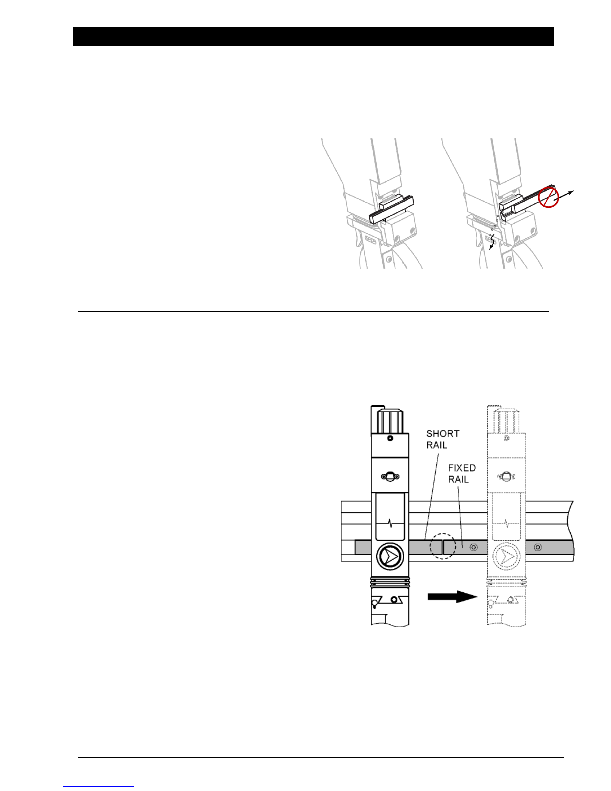
4b
4a
4c
Mount Knifeholder to Guide Bar
Easy Glider (Linear Bearing)
Manual or Pneumatic Lock
READ FIRST
Do not remove the factory-installed short rail
section from the linear rail.
This rail section must be used to install the
knifeholder onto the guide bar rail.
Failure to use this rail section when installing the
knifeholder may result in bearing damage and
void bearing warranty.
Mounted linear bearing is factory preset to be
loose in the knifeholder back plate.
Do not attempt to tighten or adjust. The
movement of the bearing allows the knifeholder
to float freely when traversing. When the
knifeholder is locked to the guidebar the bearing
movement will cease.
Mount Knifeholder
1. Choose at which the end of the guide bar the knifeholders will be mounted.
Locate and remove the #10-32 UNF screw from the end stop on the face of your guide bar.
2. Do not remove the short rail from the knifeholder bearing.
3. Unlock the knifeholder brake.
Manual Lock: turn brake knob counterclockwise.
Pneumatic Lock: pull up on traverse knob.
(Push the brake shoe up into the back plate if
protruding out.)
4. Install the knifeholder:
a. Hold the knifeholder and short rail
section together. Carefully place the rail
section into the keyway on the guide bar.
b. Align the short rail section with the fixed
bearing rail on the guide bar.
c. Slide the knifeholder onto the fixed
bearing rail.
5. Remove short section of bearing rail from the guide
bar; keep it for future knifeholder removal and
maintenance.
6. Repeat Steps 4a-4c until all knifeholders are
installed on the guide bar.
7. After all knifeholders are installed, reinstall the
#10-32 UNF socket head cap screws in the end stop
on the guide bar.
8. Reinstall blade cartridges on knifeholders (p. 23).
9. Toggle the actuator switch up on all knifeholders
to retract blade cartridges.
For knifeholder setup procedures, see pages 18-19.
www.maxcessintl.com Tidland Performance Series Manual Knifeholder MI 557416 1 Q Page 15
INSTALLATION
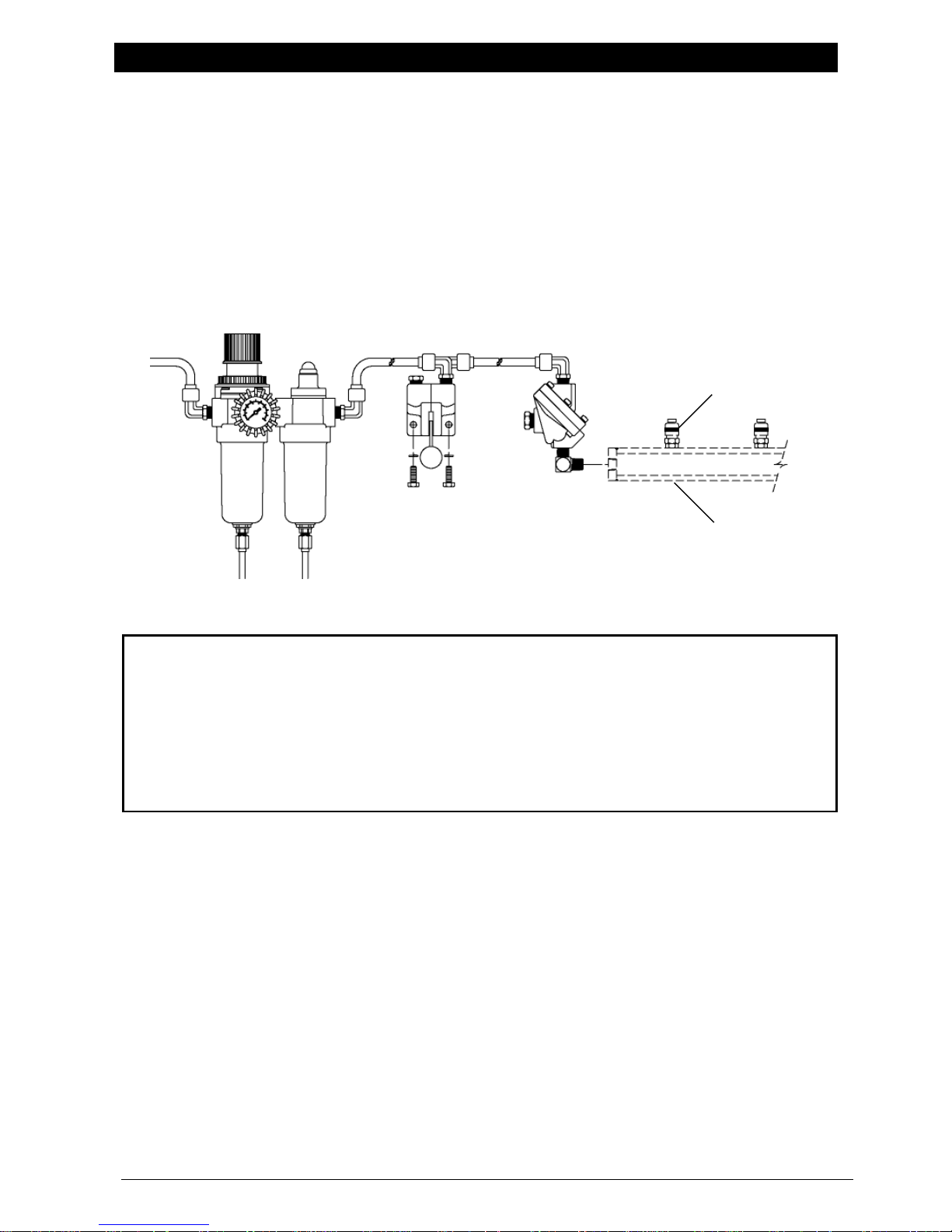
A
B
C
D
E
QUICK DISCONNECT FITTING*
AIR MANIFOLD*
*
Air manifolds and quick disconnect
fittings are also available from Tidland.
Recommended operating air pressure: 60-90 psi (4.1-6.2 bar)
This is a guideline for knifeholder setup. Actual air pressure is dependent upon application and
material.
Maximum operating air pressure: 100 psi (6.9 bar)
Clean, filtered, non-lubricated, dry air is required for optimal performance of the knifeholder.
Before operating, make sure that the air lines from the air manifold to the knifeholder are
securely connected.
Pneumatic System Requirements
To provide the correct air pressure and help achieve quality slitting, Tidland Corporation
recommends the use of a filtered and regulated pneumatic system that will prevent airborne oil
or water from contaminating the knifeholders.
The pneumatic system includes:
A) 3/8" (9.5 mm) supply air lines
B) 5 micron air filter/pressure regulator with gauge (0-100 psi or 0-6.9 bar)
C) Coalescing filter
D) 3-way manual valve with muffler
E) Quick exhaust valve with muffler
www.maxcessintl.com Tidland Performance Series Manual Knifeholder MI 557416 1 Q Page 16
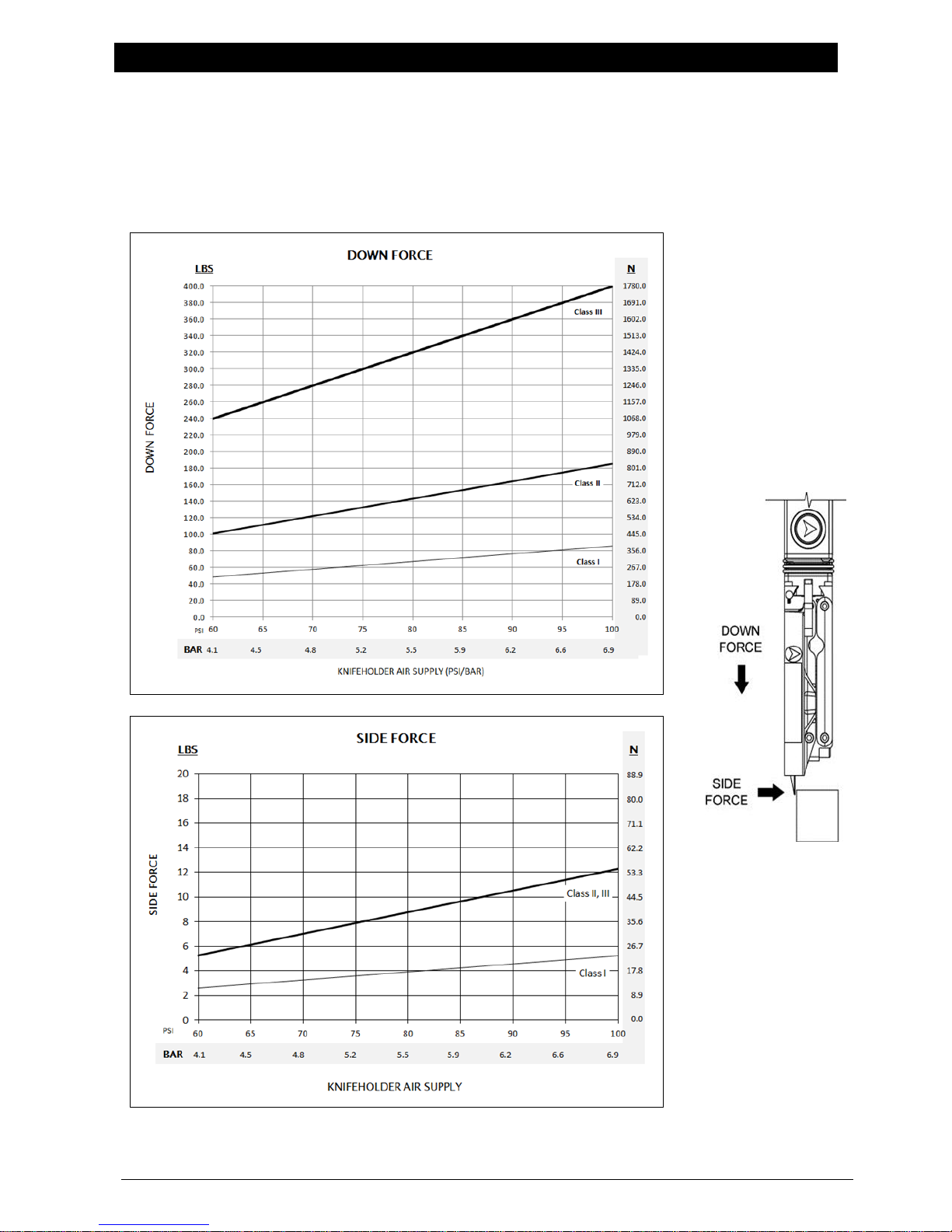
OPERATION
Operating Air Pressure
Down Force and Side Force
60-90 psi (4.1-6.2 bar) recommended
100 psi (6.9 bar) maximum
Knifeholder loads will vary slightly from averages shown.
www.maxcessintl.com Tidland Performance Series Manual Knifeholder MI 557416 1 Q Page 17
OPERATION
ACTUATOR
SWITCH
BRAKE KNOB
DEPTH CONTROL
KNOB
SETUP
BUTTONS
CONTROL
BODY
Knifeholder
Manual Lock
Ensure that:
anvil rings are in the desired slit position.
blade cartridge is securely locked to the control body.
air supply is attached and set to minimum pressure required to
slit your web material.
1. Adjust depth control knob so that it extends up from the control body:
Class I – 5/16" Class II and III – 1/2"
DO NOT SCREW the depth control knob all the way into the body.
There will be no travel during cartridge extension.
2. Toggle the actuator switch up to retract the blade cartridge.
3. Loosen the brake knob.
4. Manually slide the knifeholder along the guide bar until knife blade is
close to, but not touching, the cut side of the corresponding anvil ring.
Ensure that the knife blade is not directly over the anvil ring in
order to prevent damage by collision when the blade cartridge is
extended in the next step.
Setup
5. Press and hold one of the two cartridge setup buttons, and then
toggle the actuator switch down to extend the blade cartridge.
6. Release the setup button after the cartridge is extended
and has completed its side stroke. The knifeholder will remain
in this position until the cartridge is retracted.
7. Slide the knifeholder along the guide bar until the knife blade and the anvil ring lightly contact.
8. Tighten the brake knob. Make sure that the knifeholder remains perpendicular to the guide bar
and that the knife blade and anvil ring make contact.
9. Observe the overlap of the knife blade and anvil ring.
If the overlap is correct ― .030" (0.8 mm) ― the knifeholder is ready to slit: go to Step 11.
If overlap is incorrect, continue with Step 10.
10. Toggle the actuator switch up (retract) before making any blade overlap adjustments.
To increase the overlap, turn the depth control knob counterclockwise.
To decrease the overlap, turn the knob clockwise.
Note: One click increases or decreases the overlap .004" (0.1 mm).
One complete turn increases or decreases the overlap .040" (1.0 mm).
DO NOT SCREW the depth control knob all the way into the body.
There will be no travel during cartridge extension.
11. Toggle the actuator switch up (retract).
Note: If the blade cartridge is not retracted after completing the setup and before slitting, the
knifeholder will not function as designed and may result in poor slit quality.
Operate
12. Toggle the actuator switch down (extend) to begin slitting operation.
www.maxcessintl.com Tidland Performance Series Manual Knifeholder MI 557416 1 Q Page 18
 Loading...