

TIDELAND Nova-65 SC Operation Manual

Tideland Signal Corp.
Featur
ing Aids to Navigation
Products
Alfredo Dominguez
Paul Mueller
Larry Mitschke
Engineering Mgr.
Project Engr.
Checker
B
0276
UPDATED TO NEW FORMAT
15JUNE16
RBT
A
----
RELEASED FOR PRODUCTION
19JAN12
BO
Rev
ECO
Description
Date
By
OPERATION MANUAL
NOVA-65 SC
011.1258-00

MAINTENANCE AND OPERATION MANUAL
NOVA-65 SC/0111258-00
TIDELAND SIGNAL
HEADQUARTERS (Houston, TX)
TEL + 1 713-681-6101
FAX + 1 713-681-6233
EMAIL us-sales@tidelandsignal.com
TIDELAND SIGNAL (Nova Scotia)
DSS Marine Incorporated
TEL + 1 844 843 3526
FAX + 1 613-680-7418
EMAIL canada-sales@tidelandsignal.com
TIDELAND SIGNAL (Burgess Hill, UK)
TEL + 44 (0) 1444-872240
FAX + 44 (0) 1444-872241
EMAIL emea-sales@tidelandsignal.com
TIDELAND SIGNAL (Dubai, UAE)
TEL + 971 (0) 4-885-5842
FAX + 971 (0) 4-885-7352
EMAIL emea-sales@tidelandsignal.com
TIDELAND SIGNAL (Singapore)
TEL + 65 6333-0078
FAX + 65 6333-0079
EMAIL asia-sales@tidelandsignal.com
TIDELAND SIGNAL (China)
TEL + 86 (0) 21- 1380 101 4639
FAX + 86 (0) 21-3868-8087
EMAIL asia-sales@tidelandsignal.com
WEBSITE: www.tidelandsignal.com

MAINTENANCE AND OPERATION MANUAL
NOVA-65 SC/0111258-00
TABLE OF CONTENTS
1.0 OVERVIEW ........................................................................................................................ ..1
1.1 Features ............................................................................................................................2
1.2 Specifications ....................................................................................................................2
1.3 Technical ...........................................................................................................................3
1.3.1 Electrical .....................................................................................................................3
1.3.2 Operation Modes........................................................................................................7
2.0 INSTALLATION ................................................................................................................. 10
2.1 Unpacking........................................................................................................................10
2.1.1 Packing List/Part Numbers ......................................................................................10
2.1.2 Testing the Unit ........................................................................................................10
2.2 Mounting/Physical Installation .........................................................................................11
2.2.1 Mounting Hole Pattern .............................................................................................11
2.2.2 Installation ................................................................................................................11
2.2.3 Changing Flash Code ..............................................................................................12
2.3 Wiring ..............................................................................................................................13
3.0 OPERATION ...................................................................................................................... 13
3.1 Safety ...............................................................................................................................13
3.2 Configuration ...................................................................................................................13
3.3 LED Power Configuration ................................................................................................21
3.4 Configuring as Backup to a Rotating Beacon .................................................................22
3.5 GPS Options and Configuration ......................................................................................25
4.0 maintenance ....................................................................................................................... 26
4.1 Safety ...............................................................................................................................26
4.2 Service .............................................................................................................................26
4.3 Disassembly/Reassembly ...............................................................................................26
4.4 Moisture Protection .........................................................................................................29
4.5 Troubleshooting ...............................................................................................................29
4.5.1 Mechanical Verification ............................................................................................29
4.5.2 Configuration Verification .........................................................................................29
4.5.3 Testing the Nova-65 SC...........................................................................................29
4.5.4 Troubleshooting with SignalView™ .........................................................................30
5.0 Spare Parts ........................................................................................................................ 32
MAINTENANCE AND OPERATION MANUAL
NOVA-65 SC/0111258-00
LIST OF FIGURES
Figure 1 NOVA-65 SC .................................................................................................................... 1
Figure 2 General Arrangement ....................................................................................................... 3
Figure 3 Block Diagram .................................................................................................................. 4
Figure 4 Sunswitch Diagram ........................................................................................................... 5
Figure 5 Fail Terminal Diagram ...................................................................................................... 7
Figure 6 Cut Off Diagram ................................................................................................................ 8
Figure 7 Mounting Hole Dimensions ............................................................................................ 11
Figure 8 On/Off/Winter Charging Switch ...................................................................................... 12
Figure 9 System Wiring Diagram (Cable access is optional) ....................................................... 13
Figure 10 Internal Wiring Diagram ................................................................................................ 14
Figure 11 Blanking Panel Diagram ............................................................................................... 24
Figure 12 GPS Diagram ................................................................................................................ 25
Figure 13 Exploded Diagram ........................................................................................................ 27
Figure 14 Disassembly Diagram ................................................................................................... 28
Figure 15: EPDM Gasket .............................................................................................................. 29
LIST OF TABLES
Table 1 S4 Address Table ............................................................................................................ 16
Table 2 S4 Sequence Delay Table ............................................................................................... 18
Table 3 Default Option Table ........................................................................................................ 19
Table 4 Power Selection Table ..................................................................................................... 22
Table 5 S4 Function Table ............................................................................................................ 23
Table 6 Rotation Period Table ...................................................................................................... 24
SYMBOLS USED IN THIS MANUAL:
WARNING! Failure to heed a warning SHALL result in personnel injury or
equipment damage.
WARNING! Failure to heed this warning SHALL result in exposure to
dangerous voltage.
CAUTION! Failure to heed a caution MAY result in personnel injury or
equipment damage.
NOTE: Failure to heed a note may result in equipment or process fail
MAINTENANCE AND OPERATION MANUAL
NOVA-65 SC/0111258-00
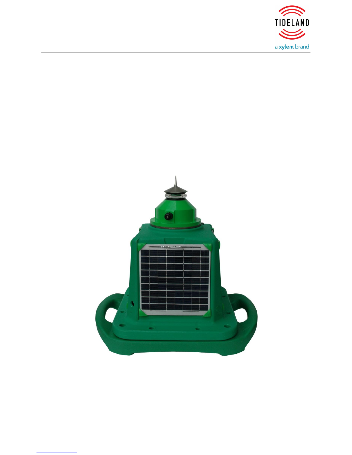
1.0 OVERVIEW
The Nova-65 SC features unique and proprietary optics which provide a 360° beam at
5°, 10° or 20° vertical divergence. Utilizing a highly efficient compact lens, the Nova65 SC is engineered to utilize the advanced and cost-effective technology of LEDs.
Solar modules and high-grade batteries are housed in a compact self-contained
marine lantern, designed for low maintenance with a projected service life of 10 years
before any significant maintenance is needed. The 10° divergence lens is ideal for
fixed or floating aids to navigation while the 20° lens provides exceptional
performance on buoys. The 5° lens can be used to meet specific needs that require
a much longer range while still using a minimal amount of power.
The Nova-65 SC’s power efficiency provides superior performance in fixed or floating
aids to navigation applications.
Tideland Signal Page 1 of 32
0111258-00 Rev. B 16-Jun-16
Figure 1 NOVA-65 SC

MAINTENANCE AND OPERATION MANUAL
NOVA-65 SC/0111258-00
1.1 Features
5°,10° or 20° vertical divergence lens
User selectable power settings for multiple visual range performance
User selectable flash characters
Available in all IALA approved colours
A constant current power source provides maximum lifetime of LEDs
Temperature compensated LED drive circuits ensure uniform brightness
with ambient temperature change
GPS Synchronisation
Full monitor and control capability
SignalView™ application to set user options
1.2 Specifications
Colours Available: ......................................................... Red, green, yellow, white, blue
Vertical Divergence: ....................................... 5, 10 or 20 degrees at 50%; ± 2 degrees
Visibility: .......................................................................... 360° horizon (omnidirectional)
Input Voltage: ..................................................................................................... 12 VDC
Power Consumption: .................................................................... Variable up to 5 watts
Power Setting: ........................................................................................ Field selectable
Quiescent Current: .............................................................................. Light only < 2 ma
With internal GPS < 3 ma
Solar Panels: ............................................ 4 Panels, each at 12 Volts 5.5 Watt Nominal
Battery Capacity: ............................................................................... 38 or 45 Amp-hour
Battery Type: ...................................................................................... Sealed Lead Acid
Reverse Current Protected
Immunity: ........................................................Per European Community EMC Directive
And IALA Guideline 1012 Level 5+
Construction: ............................................................ Rotationally moulded polyethylene
Base: .................................................................................................... Removable base
Construction: ............................................................ Rotationally moulded polyethylene
Mounting: ............................................................ 4 mounting 18 mm (0.7 in) holes on a
......................................................................... 465 mm (18 in) diameter bolt hole circle
Storage Temperature: ............................................................................... -40° to +70°C
Relative Humidity: .............................................................................. 100% condensing
Flash Codes: ..................... Up to 256 codes, field selectable or via communication link
Synchronisation: ...................................................................... GPS or hard wire options
Monitor and Control: .......................................................................................... Capable
Sunswitch Threshold: ..................................................................................... Adjustable
Tideland Signal Page 2 of 32
0111258-00 Rev. B 16-Jun-16
MAINTENANCE AND OPERATION MANUAL
NOVA-65 SC/0111258-00
Size: .....................................L 428 mm (17 in) x W 428 mm (17 in) x H 552 mm (22 in)
plus an additional 75 mm (3 in) each for the two
handles
Weight: ...................................................................................................... 20 kg (44 lbs)
Atmosphere: .............................................. Rated for continuous operation in a salty air
Wind: ...................................................................... Designed to withstand wind speeds
.. in excess of 300 kmph
(180 mph)
NOTE: Specifications are subject to change.
Figure 2 General Arrangement
1.3 Technical
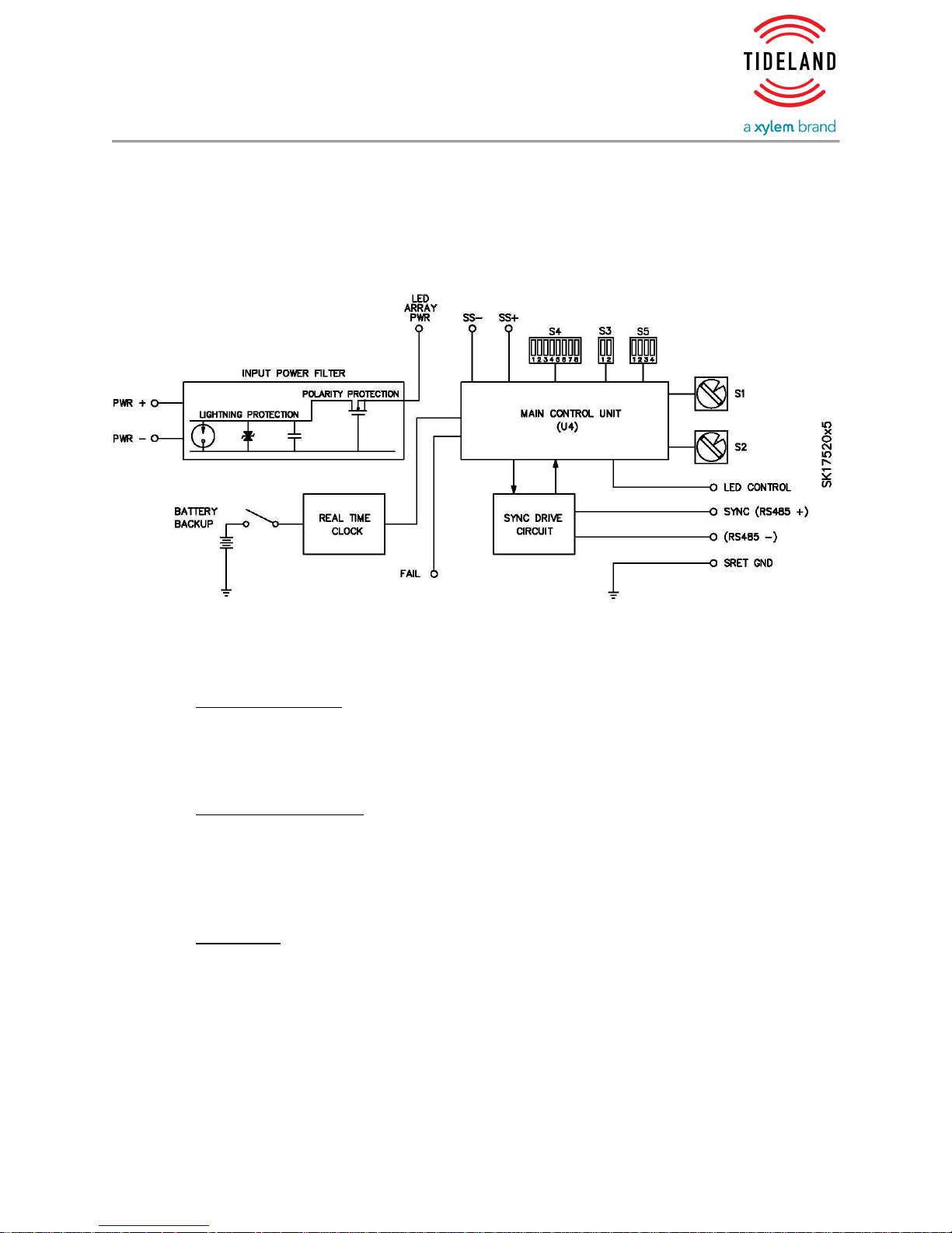
1.3.1 Electrical
The Nova-65 SC uses the MaxiHalo II control circuit. The control circuit
assembly provides terminal connections for power source, sunswitch, fail
monitor signal and synchronization signal.
Block Diagram
A block diagram of the principal parts of the MaxiHalo II Control Circuit is shown
in
Tideland Signal Page 3 of 32
0111258-00 Rev. B 16-Jun-16
MAINTENANCE AND OPERATION MANUAL
NOVA-65 SC/0111258-00
Figure 3 Block Diagram.
Figure 3 Block Diagram
Input Power Filter
Battery power is supplied to the control circuit through the Input Power Filter.
The Input Power Filter protects against input power transients, provides reverse
polarity protection and includes circuitry to arrest induced lighting surges.
Main Microcontroller
The main control unit, U1, a microcontroller, controls high-level functions of the
MaxiHalo II controller. It generates the flash code, requests and receives sync
communications, receives inputs from the sunswitch (photocell) and
configuration information from switches S1, S2, S3, S4, and S5.
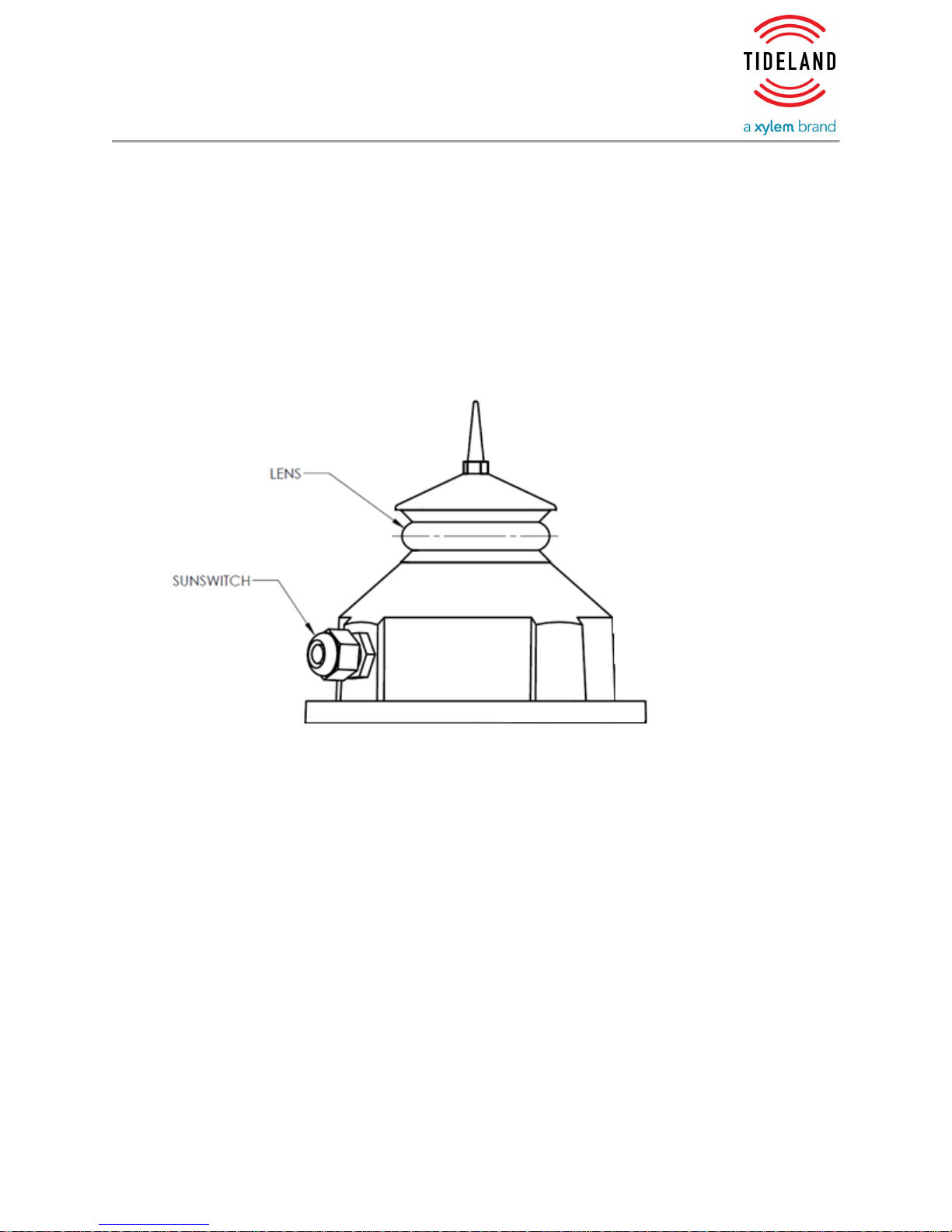
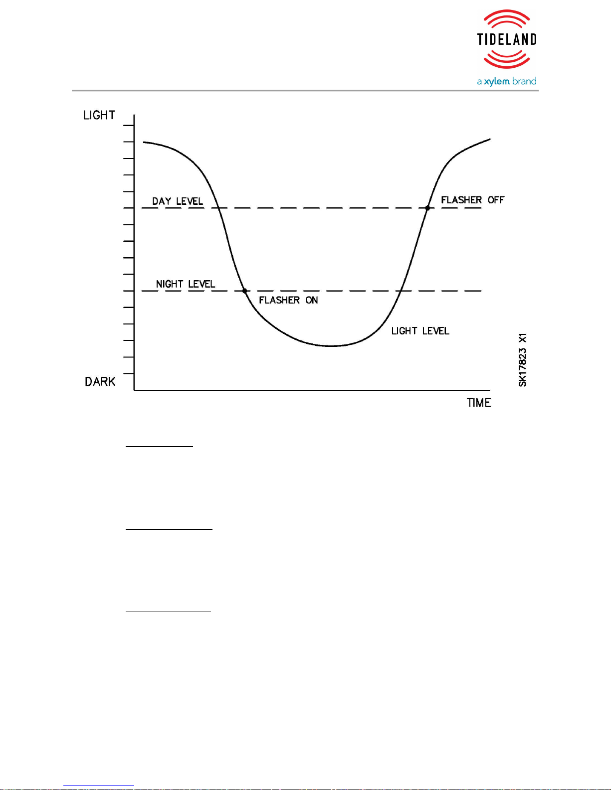
Sunswitch
The sunswitch monitors ambient light level and produces an output signal to be
measured by the MaxiHalo II controller. Day and night threshold levels can be
set using SignalView. To avoid false activation, the system is designed to
require the crossing of two light levels to switch to either day or night operating
modes. See Figure 4 Sunswitch Diagram.
Tideland Signal Page 4 of 32
0111258-00 Rev. B 16-Jun-16
MAINTENANCE AND OPERATION MANUAL
NOVA-65 SC/0111258-00
Figure 4 Sunswitch Diagram
Flash Codes
256 flash codes are pre-programmed into the MaxiHalo II controller and are
user-selectable by SignalView, or by using the hexadecimal (sixteen position)
switches S1 and S2. Please see Code Selection Guide (part number 011.1092-
00).
Adjusting Power
Power to the LEDs can be set by using SignalView to adjust output as a percent
of full power (0 to 100%). If using the 4-position power switch, S5, there is a
choice of 16 different power levels (see Section 3.3 LED Power Configuration,
below).
Synchronization
The ASCII Sync signal uses a proprietary Tideland protocol that employs
transmitted serial data to control, monitor and synchronize multiple flash units.
This system is compatible with SignalView or NavLink systems. It primarily is
used to synchronize flashes of several units that use ASCII Sync and to control
Main/Standby lanterns. The protocol also synchronizes on-at-night and off-atday switch over for all connected lights.
Tideland Signal Page 5 of 32
0111258-00 Rev. B 16-Jun-16

MAINTENANCE AND OPERATION MANUAL
NOVA-65 SC/0111258-00
GPS Synchronization
GPS synchronization is enabled when the MaxiHalo II controller is fit with an
internal GPS receiver and antenna.
A GPS synchronized light flashes in synchronization with the Coordinated
Universal Time (UTC) of Global Position Satellites. Thus, all GPS-equipped
Tideland flashers with the same flash code flash in unison without having
interconnected sync terminals or additional radio links.
A GPS configured Nova-65 SC can be synchronized with other standard ASCII
sync lanterns by connecting MaxiHalo II controller sync terminals. In this case,
the Nova-65 SC acts as the synchronization master, producing the ASCII
character to synchronize other lanterns. The light retains its remote monitoring
capability.
Optional Real Time Clock (RTC)
The RTC is an integrated circuit interconnected to the main microcontroller. It
keeps twenty-four hour time and date information. The RTC can be set and
read using SignalView. When main power is removed from the light, a lithium
battery maintains date and time. The primary function of the RTC is to program
the light to disable during the seasonal period when there is no vessel traffic,
and to re-enable during the season when vessel traffic is active.
RTC Battery
The RTC lithium battery is used for power when main power is disconnected
from the MaxiHalo II controller. S3-2 is provided to disconnect the lithium
battery from the circuit when the flasher is in storage. Before deployment when
desiring to use the RTC, S3-2 must be turned on.
LED Voltage Monitor
The LED Voltage Monitor measures LED array voltage, which is displayed in
SignalView. LED voltage varies from color to color and LED array to LED array.
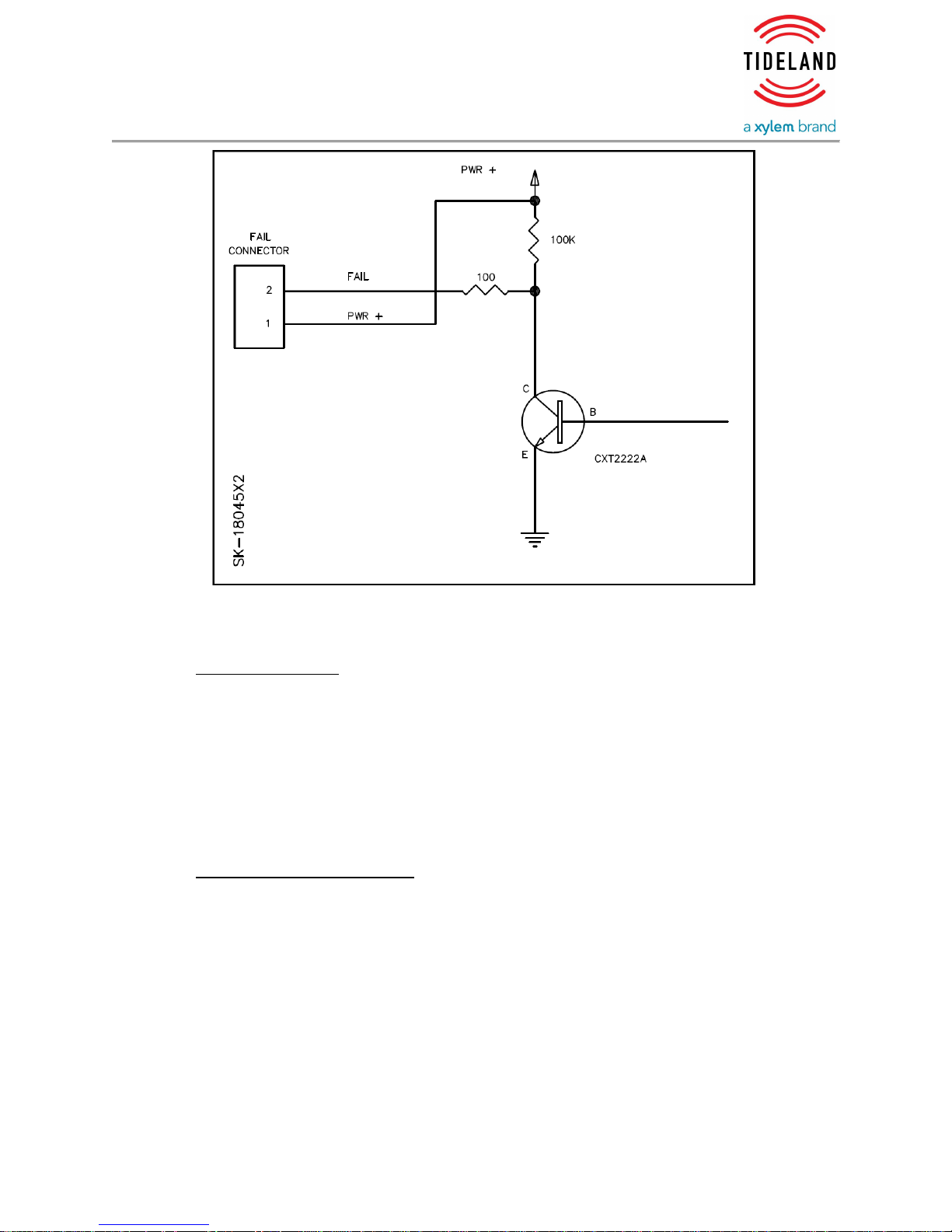
Fail Terminal
The Fail Terminal (Figure 5 Fail Terminal Diagram), used to signal a failure to an
external device, is electrically switched to ground under normal operating
conditions. This is the default mode in a fail-safe system where either lack of
power or a failure asserts a fail condition. In event of failure or loss of power, the
terminal is open. Signal current is limited to twelve milliamperes. The default
logic can be reversed (open during normal operation, switched to ground during
failure) using SignalView to unselect “Invert Fail Output”.
Tideland Signal Page 6 of 32
0111258-00 Rev. B 16-Jun-16
MAINTENANCE AND OPERATION MANUAL
NOVA-65 SC/0111258-00
Figure 5 Fail Terminal Diagram
LED Drive Circuit
A high efficiency DC to DC converter provides virtually constant luminous output
under a wide range of input power conditions. The DC to DC converter
compensates for temperature changes of the LED array, conserving power at
low ambient temperatures where LEDs are most efficient but batteries are least
efficient. LED power is reduced below 100%, using SignalView or switch S5
(Section 3.3 LED Power Configuration, below).
1.3.2 Operation Modes
Main/Standby Installations
When redundancy is required, units are paired as Main and Standby units with
an external cable. The MaxiHalo II controller supports up to eight pairs (sixteen
units) in this configuration. During normal operation, Main units (with odd
addresses) send a signal via ASCII sync line that tells Standby units (with even
addresses) that the Main units are operating normally. When a “Main Fail”
signal is received, or when communication is lost, the Standby unit activates.
The Standby unit remains activated until it receives a “Main OK” signal from its
Main light.
Tideland Signal Page 7 of 32
0111258-00 Rev. B 16-Jun-16
 Loading...