


TACC-IIa

General Information
TACC-IIa, (Built in 1991)
The Main PCB is different from TACC-IIR.
TACC-IIa, (Built in 1992)
Timing Disk changed to accommodate the absence of the Lower Sensor PCB.
TACC-IIa (Built in 1993)
Serial Number information
Problem Identifi cation By Component

TACC-IIa - Production began 1994
The diameter of the Vend Tubes were increased to accomodate international coins.
The Solenoid mounting bracket moved approximately one inch toward the center
The new Main PCB is backward compatible with older units.
To stop the “tube dump” feature, the Vending Keyswitch must be turned to the
TACC-IIa with rear door.
This unit was equipped with a door on the front and rear of the unit. The solenoid was
TACC-IIa built for overseas applications (Thailand)
TACC-IIa redesign for Sentinel cabinet design. Production began late 2006.
The Control Panel Chassis size increased to be interchangeable with Sentinel, TACC-V
The size of the back wall on the unit was reduced by approximately half. Only (2) 3/4”
Problem Identifi cation By Component

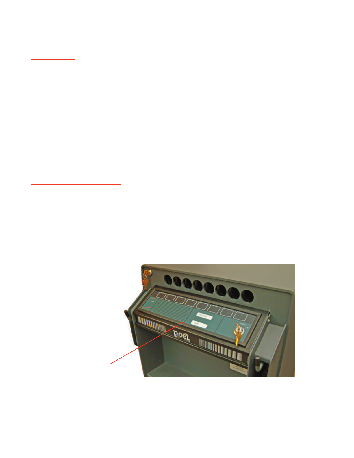
The Control Panel basically is a
Touchpad consisting of 8 vend buttons, the
There a 4 vend motors. Each motor turns a cradle back and forth to dispense tubes from two
This is an indication that the unit “saw” you press the button. The button and
It is important that you verify that a response is given by the Control Panel when
If no response is indicated when the vend button is pressed, (the LED’s do not re-
spond), the unit does not “see” the button.
The “STACKER FULL” LED is not used by the TACC-IIa.
Door timer or Alternate Vend timer will not start
The Alternate Vend delay timer cannot be started if the unit “sees” the door in the un-
The problem may be related to the button or the Manager Keyswitch.
To isolate the problem, perform the following test:
Problem Identifi cation By Component
Drink spills
Worn/stuck buttons
LED’s do not illuminate
Static Discharge
Control Panel
Problem Identifi cation By Component

Sprung Door
The door tends to push outward. Customers usually report they have to push in on the door to
Sagging Door
Worn Hinges
Problem Identifi cation By Component

The fuse is located under the Control Panel, next to the serial # sticker.
This “click” indicates AC power is being applied to the Power Supply. This indicates
Fuse Cap
Fuse Holder Assy
Problem Identifi cation By Component

Keyswitch (Courier/Instant Access)
The Instant Access Keyswitch is mounted below the Manager Keyswitch on the door.
The Keyswitch is spring loaded and should return to the off position when released.
The Keyswitch is supplied with 4 keys and an aluminum tag which has a
The Keyswitch is a restricted keyway. Replacement keys cannot be made locally. The key
The
To open the door using the Instant Access Keyswitch, turn the Instant Access Keyswitch ON and
The
The
The Vend Delay timer will continue to advance.
Instant Access Key Operation Options:
Single Key:
Dual Function:
Keyswitch (Dispensing/Vending)
Problem Identifi cation By Component

Keyswitch (Manager/Time Delay)
The Keyswitch is spring loaded and should return to the off position when released.
The Keyswitch is supplied with 4 keys and an aluminum tag which has a
The Keyswitch is a restricted keyway. Replacement keys cannot be made locally. The key
To start the Door opening delay timer, turn the Manager Keyswitch and release it, then press
A91 series units did not require
The
To isolate the problem, perform the following test:
The Manager
The 30-second Alternate Vend feature cannot be activated if no keyswitch is connected to to the
Current Production Door with
hinges on the left
Manager/Time Delay
Keyswitch
Instant Access/Courier
Keyswitch
Old Style Door with hinges
on the right
Manager/Time Delay
Problem Identifi cation By Component
Keyswitch

Lock (Door Bolt)
The
The Door Bolt Lock is supplied with 2 keys and an aluminum tag, which has a key code,
The Door Bolt Lock is a restricted keyway. Replacement keys cannot be made locally.
The key code must be supplied to Tidel and only then can Tidel supply replacement keys.
The Door Bolt Lock operates the door locking bar by means of a cam.
The Tube Loading Gate Lock lock is located in the top right corner of the unit.
Lock (Tube Loading Gate Lock Bar)
Door Bolt Lock
Tube Loading Gate Lock
Problem Identifi cation By Component

Tubes or rolls of
Problem Identifi cation By Component

The Main PCB controls all functions of the TACC-IIa.
The Main PCB houses the Service Diagnostic Switch and the
The
The
Door Opening Delay Options:
Instant Access Key Operation Options:
Single Key:
Dual Function:
Problem Identifi cation By Component

The Motr Controller PCB controls the motor and vending functions.
The vending function of a TACC is performed by the following:
A Vend Motor runs continuously
Typically a defective drive transistor, replace Motor Controller PCB.
To diagnose Motor Controller PCB problems, perform a power reset and LISTEN for the follow-
The unit makes a loud popping noise or binds. Probable jam in the cradle area
The unit vends a tube, works properly afterward. Tube or coins were jammed.
Wait light fl ashes when a button is pressed
A Vend Motor does not run.
Problem Identifi cation By Component

TACC-IIa units with serial #’s beginning with A91, had Power Supplies mounted on the maga-
The Power Supplies are auto ranging and can be connected to 120vac or 240vac circuit without
The Power Supply converts incoming AC voltage to +12 and +5vdc.
No LED’s illuminate on the display
The
No vend motors will operate and the door solenoid will not activate
Erratic LED behavior
Problem Identifi cation By Component

Read the following completely BEFORE attempting to adjust the
Turn the R31 Potentiometer VERY SLOWLY to raise or lower the output
voltage of the Power Supply.
Do not perform a voltage adjustment if the +5vdc output is correct!
Do Not adjust the voltage above +5.10vdc.
Do Not attempt to adjust the +12vdc, -12vdc or +24vdc if the +5vdc is
correct before making the adjustment.
Do Not apply pressure to the R31 potentiometer when adjusting. Damage will occur.
Problem Identifi cation By Component

Door Sensor
The Door Sensor is located inside the unit, on the left side of the door frame.
justment.
To adjust the Door Sensor, loosen the 2 screws at rear of bracket to and lower the
The Door Sensor may be broken or out of the bracket.
Do not attempt to “splice” a replacement Door Sensor into the existing wiring har-
Problem Identifi cation By Component

The Door
Typically, when the solenoid energizes, a faint mechanical noise can be heard (the plunger be-
Problem Identifi cation By Component

The gear on the Vend Motor shaft engages the gear on the Cradle to rotate the Cradles for
To isolate the defective component, perform the following:
To isolate the defective component, perform the following:
Problem Identifi cation By Component
 Loading...