

Page 1

ASSEMBLY AND OPERATION MANUAL
for the G2 Tracksetter
by Tidd Tech
You will find the most up to date version of this document at :
www.tiddtech.com/manuals.htm
1100 Roundhouse Road
Spooner, WI 54081
Toll Free: 1-877-843-3832
www.tiddtech.com
PN 040101-02 G2 Tracksetter, Assembly and Operation Rev 1/2019
1
Page 2

SAFETY
This is the part of the manual that contains IMPORTANT safety information. Many
products purchased in today’s litigious society come with volumes of so called “safety
information” complete wi th diagrams and intelligence insulting text that are so ridiculously
obvious that most people ignore the entire section. We have left out the ridiculous and
obvious in order to provide you with concise information we believe you can use. It is simply
not possible for a manufacturer to anticipate all of the ways an end user can misuse a product
to cause damage or injury, but below are the issues we believe a reasonable and responsible
operator should pay attention to. Please read this manual completely before operating your
machine. If you discover something you believe we should add to this manual, by all means
call us, toll free at (877) 843-3832. We do appreciate your feedback!
1. The G2 Teeth (and Tracksetter Teeth) are VERY SHARP, and should be treated with respect.
Never reach under the front edge to move the groomer. Before touching the groomer, please get
down on your hands and knees and LOOK at the teeth (and touch them) so you are aware of where
and how sharp they are.
2. Be careful lifting the groomer. Its weight is often increased by snow piled on top. Deep or icy
snow makes moving the groomer even more hazardous. Be sure you have secure footing, bend your
knees, and keep your back straight. In our experience, the most common injury to trail groomers is
back strain from yanking implements and snow machines around, and this is completely avoidable.
Keep fingers clear of the hitch when you are hooking up to the snow machine.
3. Maintain a safe distance and proceed slowly when operating near skiers or pedestrians on the
trail. Grooming a trail with skiers present should be looked upon as an opportunity to offer some
friendly customer service – at a minimum a wave or hello. If your customer looks like they need some
assistance, shut down your stinky, noisy snow machine and offer some. Those skiers are the reason
you have a job so please do not subject them to injury, intimidate them or otherwise spoil their
experience.
4. You may have prior experience with Tidd Tech Trail Tenderizer or Snow Roller products.
Please note that the G2 employs a spring trip on the Toothbar and DOES NOT HAVE A
BREAKAWAY SHEAR PIN! The spring trip offers many advantages over a shear pin system,
enabling the machine to encounter obstructions, trip the toothbar and reset without interrupting
operation. HOWEVER, the spring trip will not protect anything other than the teeth. If you wrap the
G2 frame around a tree, post or other obstruction, you will almost certainly damage the G2, the hitch,
your snow machine, and most importantly, yourself (see safety issue #6, below).
5. You will not find any handles, foot rests or seat belts on the G2 because it is NOT intended for
riders, period. If you need to add weight, see the appropriate section in the manual.
6. Finally, please remember that normal grooming speed is somewhere between 5 and 15 mph
(usually 5-10 mph, although the design innovations of the G2 allow for grooming at up to 15 mph in
some conditions). This implement is designed to work in that approximate speed range, and not only
will this speed range yield the best grooming results, but this speed range also will give both the
operator and equipment a reasonable safety margin for error. If you operate this or any other
implement behind your snow machine faster than 20 mph (even when you are not grooming), you are
simply an irresponsible FOOL looking for an accident to happen, and all of the ridiculous text and
diagrams we left out of this safety section would have been lost on you anyway.
PN 040101-02 G2 Tracksetter, Assembly and Operation Rev 1/2019
2
Page 3

Unpacking and Assembly
Tools Required: (2) ¾” end w r enches or equivalent, (2) 9/16” end wrenches or
equivalent, knife to remove packing material
1. Remove all of the Tracksetter components from the box and discard any packing material.
2. Remove flange bearings from their packaging. Holding bearing together as it comes out of the
bag, place each bearing onto post located at the bottom of the actuator. Line the actuator up with the
raised end of the actuator arm. Actuator motor should face away from arm. Rotate bearing flanges
into the actuator arm until you are able to insert the 3/8” x3/4” hex bolts through the top set of holes
on the arm and the bottom set of holes on the bearing flanges. Attach nuts until finger tight. Now
rotate loose end of the bearing flanges towards the actuator motor while pivoting the top of the
actuator towards the arm. Eventually, the remaining sets of holes will line up. Insert hex bolts and
nuts. Tighten all fasteners.
3. Assemble the three main components as shown in the pictures, using the ½” x 6” Hex Bolt,
bronze bushings and the locknut. The lock nut need only be tightened to the point that it engages the
nylon locking threads. It acts as a pivot pin only and therefore it is NOT necessary to tighten to the
point that it is snug against the arms on the clamp assembly. There should be play between the
components that this bolt passes thru to allow for free rotation. Please note that this pivot has been
PN 040101-02 G2 Tracksetter, Assembly and Operation Rev 1/2019
3
Page 4
designed intentionally with some “play” to give the Tracksetter some freedom to move in both the
1/2x6 bolt, with lock nut through
Tighten ½” bolt just
“yaw” axis and “roll” axis.
three assemblies. DO NOT
OVERTIGHTEN! Just engage
lock nut threads securely.
3. Attach the free end of the actuator to the ears as shown. Do not over tighten the ½” bolt at the
bottom of the actuator. This bolt acts simply as a pivot pin, and the locknut need only be tightened
enough that the bolt is into the nylon locking threads on the nut to insure that the nut will not come
off.
enough to engage the lock
threads securely.
4. Examine your gas springs closely: There should be a small wire spring clip at each of the two end
fittings on each gas spring. Rotate one of these off to see how it comes out of the hole in the fitting,
and then practice replacing it. You must remove these wire retainers each time you wish to mount or
dismount a gas spring from a ball end mount on the Tracksetter. Now remove both of the retainers
from one of the gas springs, but don’t lose them! Take this gas spring and compress it just a bit a few
times on the floor so you unstick it and get it moving.
5. Pop this single gas spring into place on either side of the actuator and clamp arm assembly (save
the other one for use under certain conditions – see operation section). Be sure to install the gas
spring with the “fat” end closest to the actuator. That way the rod (skinny) end is normally hanging
down when the Tracksetter is raised. This keeps the seals inside the gas spring lubricated. Replace
PN 040101-02 G2 Tracksetter, Assembly and Operation Rev 1/2019
4
Page 5

the wire retainers to hold the spring on the ball mounts. Look at your other spring if you can not
Gas Spring
remember how the retainer worked.
You are essentially done and ready to hang your Tracksetter on the G2 tool bar. We recommend
unscrewing the clamp knob for the first time and removing the J bolt while you hang the Tracksetter.
Once the Tracksetter is sitting on the toolbar correctly, you can replace the J bolt and clamp knob.
See the picture on the front of this manual for an assembled Tracksetter properly mounted on
a G2.
Connect the leads to the appropriate set of wires on the G2 groomer. If you have a single
Tracksetter, make sure to coil the unused set of leads up on the “Roll Bar” on the G2 and tape or
wire tie them securely so they will not get loose and become tangled in the teeth. Test the operation
of the actuator if you have power available for the control box. If this is not convenient, save testing
for later when you are hooked up to your snow machine.
Your Tracksetter is ready to go – you may loosen the Clamp Knob and slide the Tracksetter to
the desired position on the Tool Bar. Note – you do NOT need to remove the J bolt or Clamp Knob.
Just grab the rear of the Tracksetter pan and lift slightly to take some weight off as you slide and it
will go easily. Remember later on that this will not be easy if you let ice accumulate on the Tool Bar –
Clean off your machine each time you are done grooming.
Electrical System
See the G2 Trail Groomer Manual for general info on the electrical system.
Care and Maintenance
See the G2 Trail Groomer Manual for general info on maintaining all G2 components.
Tracksetter Operation
Note: You should be familiar with the G2 Trail Groomer Manual before reading this section. You may
want to have that document available as you read this because it will help to understand the
concepts.
PN 040101-02 G2 Tracksetter, Assembly and Operation Rev 1/2019
5
Page 6

NOTE – the first time the gas spring is compressed after not working for a while (like
you also insure that you do not have ice built up on the tracksetter or spring, inhibiting operation.
The G2 Tracksetter has a unique close coupled, rigid arm design that offers many advantages over a
conventional floating pivot design. However, a full understanding of how the G2 Tracksetter works is
necessary to completely take advantage of its features.
The G2 Tracksetter main pivot (the gold colored grade 8 bolt) is located just above the comb on the
G2 Trail Groomer. The Tracksetter is rigidly attached to an arm that rotates about this pivot as the
implement follows the undulating terrain. Because this pivot point is located right at the comb where
the entire implement rotates as it follows the ups and downs of the terrain, the “pitch” of the
Tracksetter is always parallel to the surface of the trail. One or two gas springs provide a near
constant force on the Tracksetter, compressing and extending as the Tracksetter rotates. Please
note that this pivot has been designed intentionally with some “play” to give the Tracksetter some
freedom to move in both the “yaw” and “roll” axis.
overnight or longer) it will have some “sticktion”, meaning that it will require more force than
normal to break it loose and get it operating smoothly. Usually, the spring will compress right
away when you first run the Tracksetter down into the snow. However, it is good practice to
either manually push against the Tracksetter to compress the spring a bit while the Tracksetter is
in the up position or run it down once and observe that it is compressing correctly. Once it moves
even just a little, it will work consistantly thoughout the entire range of motion. By checking this,
The G2 Tracksetter is raised and lowered by means of an electric actuator. This actuator i s always
either fully extended or fully retracted and never should be operated at a midway position. When
done grooming actuators should be left partway up or down – not fully extended or retracted.
You can tell when the actuator is at full extension or retraction when it makes a clicking sound as the
control button is pressed. This is the sound of an internal clutch similar to that on a cordless drill and
is normal when the actuator reaches travel limit.
Either one or two gas springs may be installed in various combinations in order to obtain the desired
amount of force on the Tracksetter (two 75 lb springs are supplied with your G2 Tracksetter). HERE
IS THE KEY TO UNDERSTANDING THE PROPER FORCE ON THE TRACKSETTER: The gas
springs must not supply so much force that the comb on the G2 Trail Groomer lifts off of the snow
(see diagram). In our experience, a single 75 lb gas sp ring provides the right amount of force if no
additional weights are added to the G2 Trail Groomer (see the section on adding weight). If you wish
to increase the force on the G2 Tracksetter beyond a single 75 lb gas spring, then it is recommended
that you add weight to the G2. By t he way – it does not matter which side the single gas spring is
mounted, and the resulting force is not “off center” – everything works just fine this way.
If the rear of the G2 Trail Groomer is forced upwards off of the snow, the pivot point rises as well.
This causes the Tracksetter’s angle of attack, or pitch, to point upwards and the Tracksetter will climb
out of the snow, even though you have increased the force upon it. You will always get the best track
if the comb on the G2 is fully depressed and flexed (you will, of course, get better combing, too).
PN 040101-02 G2 Tracksetter, Assembly and Operation Rev 1/2019
6
Page 7
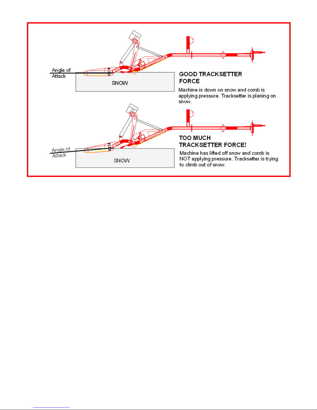
Lesson: Make sure that your G2 comb is always FULLY FLEXED, and the Tracksetter is not
forcing the comb up off of the snow!
The reason for this is simple, but not intuitive: The G2 Tracksetter gains a tremendous advantage
because the “pitch” is fixed to plane parallel to the trail surface. As an analogy, imagine the work you
can do pulling a hoe or rake through soil with a normal length handle, and then picture trying to do
the same work with a 6” long handl e. Aside from having to bend down, you have also lost the
leverage advantage of the long handle that helps work against the resulting rotational force as you
pull the hoe or rake through soil. With the long handle, you do not have to exert much down force or
fight a large rotational force to get the hoe or rake to bite – you basically just have to pull on the
handle. The G2 Tracksetter works on the same principle! Other tracksetters have a pivot right at the
center of the tracksetter (a short stubby hoe/rake handle) and must apply sufficient down force to
keep the tracksetter planing on the snow, as well as a pulling force.
Please note that the gas spring ex erts a rotational force on the Tracksetter (and you don’t need
much, see our above hoe/rake analogy). This is not one for one equivalent to the down force applied
by weight plates added to the G2. It is not necessary, for example, to add 75 lbs of weight plates on
each side of the implement just because you have added the second 75 lb gas spring. In fact, we
have found that 50 lbs per side is the most ever needed, and often 25 lbs per side is sufficient. Some
experimentation is required to find the best combination for your terrain and conditions. In theory, you
will get a more dense and durable track with the more force applied, but the tradeoff will be the
added pulling weight of the implement. The G2 Tracksetter is designed to apply force in the most
efficient manner possible, thus requiring the least amount of total implement weight.
The G2 Tracksetter has a sideplate attached to each side. Please observe how this sideplate not
only provides positive tracking and keeps the tracksetter from sliding sideways, but also protects the
teeth and trackshoes from damage if the Tracksetter is run across a surface other than snow (like a
PN 040101-02 G2 Tracksetter, Assembly and Operation Rev 1/2019
7
Page 8

road or cart path). These sideplates may be rotated to a total of two positions as they wear, then they
need replacement (we stock them).
The sharp teeth on the G2 Tracksetter are replaceable and are identical to the teeth on the G2. Call
us for replacement teeth when you need them. The center tooth acts to protect the nose of the
trackshoe (very expensive to replace) and should be replaced if it wears down.
Especially during early season grooming, the teeth on the Tracksetter may pick up debris. If you
suddenly observe a less than perfect track as you are grooming, stop and check to see if there is
something stuck on the teeth of the Tracksetter. They are as self cleaning as possible, but debris still
may collect there.
LIMITED WARRANTY
For Tidd Tech Products
by
TIDD TECH
Products from Tidd Tech carry a one year warranty. If the equipment fails due to a defect in
materials or workmanship within one year from the date of purchase, Tidd Tech, will repair or replace
the part free of charge.
This warranty is not transferable and does not cover damage resulting from anything other than
defects in material or workmanship. This warranty does not cover damage caused by unreasonable
use, nor replacement of non-defective parts that may wear and need to be replaced within the
warranty period.
For warranty service you must, at your own expense, arrange to deliver or ship the product or part(s)
for warranty repairs to Tidd Tech at the address below.
This limited warranty is in lieu of all other express warranties. Tidd Tech shall not be liable for any
special, incidental or consequential damages.
This warranty gives you specific legal rights, and you may also have other rights which vary from
state to state.
1100 Roundhouse Rd., Spooner, WI 54801
Phone: 1-877-843-3832
Email: [email protected]
www.tiddtech.com
PN 040101-02 G2 Tracksetter, Assembly and Operation Rev 1/2019
8
 Loading...