

Page 1
Part # (11-0096-11)
Page 2

This manual covers your new
2009 TidalFit
Page 3

TABLE OF CONTENTS
Congratulations..............................................................
Safety Warnings..............................................................
Line Drawing Key...........................................................
TidalFit Conguration and Water Capacities...............
Electrical Requirements and Installation.....................
Basic System Features and Functions...........................
60 Hz Electrical Wiring...........................................
50 Hz Electrical Wiring...........................................
TidalFit Start Up..............................................................
Selecting a Location..............................................
Inspection..............................................................
Filling the Pool with Water......................................
Turning the Power On............................................
Verifying Water Circulation.....................................
Testing the GFCI Breaker......................................
Priming the Pump..................................................
Water Preparation.................................................
ML 700 Panel User Guide..............................................
Diagnostic Messages.....................................................
Various Exercises..........................................................
Rowing Exercise....................................................
Upper Body Exercise.............................................
Treadmill/Advanced Swimming.w/Superswim.......
1
3
5
6
7
8
9
11
12
12
13
13
14
14
14
15
15
16
25
30
31
32
33
33
33
34
35
36
36
37
37
38
39
40
40
Maintaining Your TidalFit...............................................
Draining Your Pool................................................
Pillow Care............................................................
Jet Care................................................................
Removing, Installing, and Cleaning Filters...........
Winterizing Your Pool............................................
Replacing the Light Bulb.......................................
Pool Cabinet Care.................................................
Cleaning Your Pool Interior....................................
Cover Care...........................................................
Chemical Treatment of Water...............................
Water Chemistry............................................................
Water Treatment Glossary....................................
Page 4

TABLE OF CONTENTS cont....
Spa Chemicals Glossary..........................................
Maintaining the Proper pH....................................
Warranty Information....................................................
Interior Pool Diagram...................................................
45
46
47
53
Page 5

1
Before you do anything else, make sure you
register your new TidalFit exercise pool.
Congratulations...
Congratulations on the purchase of your new TidalFit. We know
you will enjoy your TidalFit. Not only will your TidalFit be a physical
workout, but also it will be relaxing and fun. We believe this
will be an indispensable part of a healthy lifestyle. The TidalFitl
lifestyle is one that encourages health and well-being.
Owning a TidalFit brings some responsibility. With proper care,
your TidalFit will provide years of enjoyment and therapy for your
family and friends. Please take time to read and understand all of
the instructions provided before you install your TidalFit exercise
pool. This owner’s manual is meant to be a supplement to the
training you should receive from your dealer when you purchase
and start up your TidalFit for the rst time.
Please remember your TidalFit is a powerful piece of electrical
equipment. It is extremely important that you have it properly
installed to ensure safe use. This manual explains safety
precautions, installation instructions, and operating and
maintenance procedures. If you have any questions regarding
this manual, please call your competent dealer, who will be
happy to further assist you.
Page 6
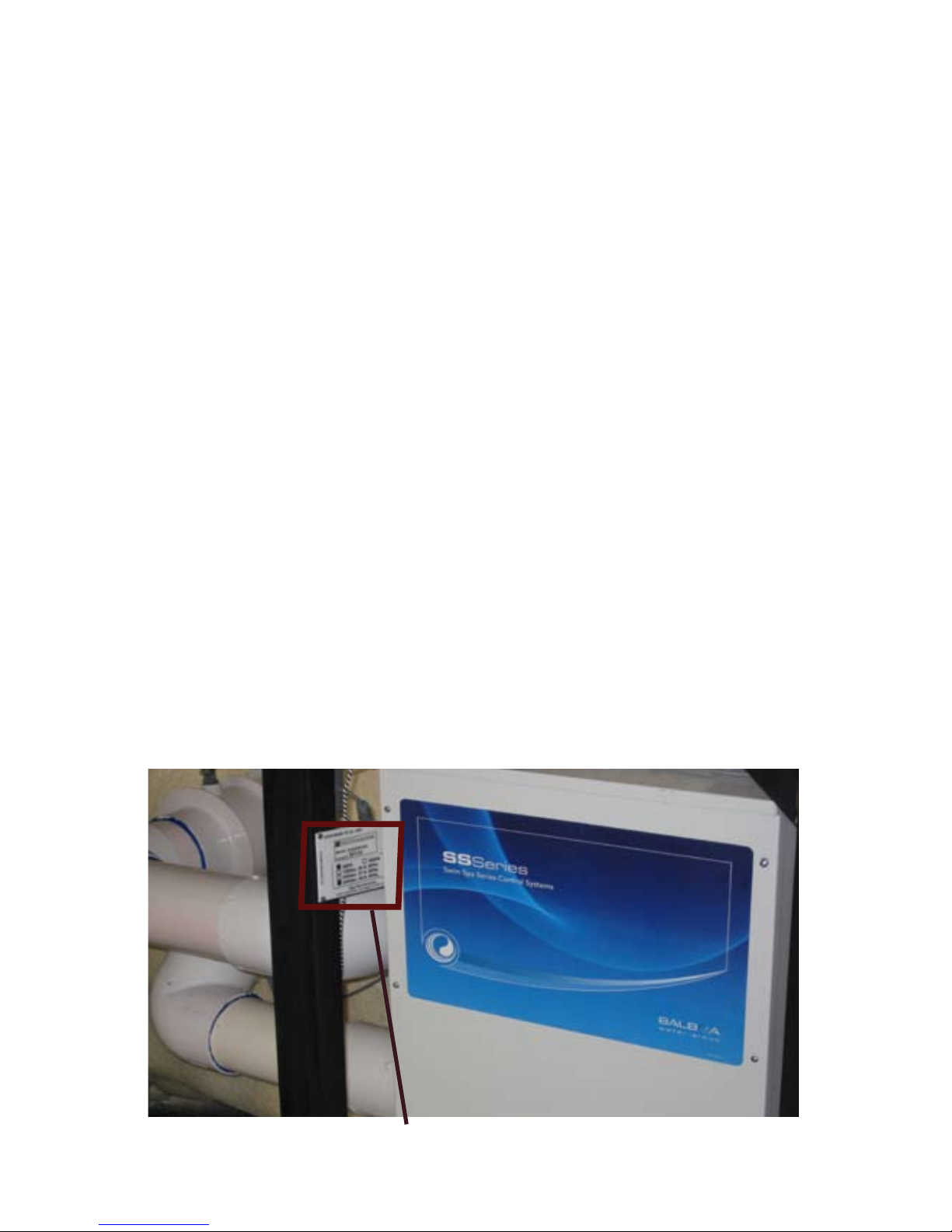
For your future reference and convenience, please record the Serial and Model number along with the installation date in the spaces
provided below. STORE THIS MANUAL WHERE YOU CAN EAS-
ILY FIND IT WHEN NEEDED. The serial and model numbers are
mounted on the base of the equipment enclosure area, as shown
below.
Spa Serial Number_____________________________________
Spa Model Number_____________________________________
Spa Installation Date____________________________________
Dealer Name, Address, and Telephone Number
____________________________________________________
____________________________________________________
____________________________________________________
Diagram of Where to Find Serial Number
2
Serial Number Information
Page 7

3
PLEASE TAKE THE TIME TO READ ALL OF THESE WARNINGS AND
CAUTIONS PRIOR TO USING YOUR POOL
PLEASE, be a responsible TidalFit owner. When installing and using this
pool, always adhere to basic safety precautions. Be sure to list emergency
telephone numbers at the telephone nearest the pool, including physician,
hospital, ambulance, police, and the re department. Be certain to explain
safety precautions to all new or occasional users of your pool. Remember,
they may not be aware of the possible risks associated with the pool water
temperature.
Have at least one family member learn CPR (cardiopulmonary resuscitation). IT COULD SAVE A LIFE!
1. READ AND FOLLOW ALL INSTRUCTIONS!
2. WARNING - To reduce the risk of injury, do not permit children to use
this product unless they are closely supervised at all times.
3. A wire connector is provided on this unit to connect a minimum 8 AWG
(8.4 mm ) solid copper conductor between this unit and any metal
equipment, metal enclosures of electrical equipment, metal water pipe, or
conduit within 5 feet (1.5 m) of the unit.
4. DANGER - Risk of Accidental Drowning - Extreme caution must be
exercised to prevent unauthorized access by children. To avoid accidents,
ensure that children cannot use this spa unless they are supervised at all
times.
5. DANGER - Risk of Injury - The suction ttings in this area are sized
to match the specic water ow created by the pump. Should the need
arise to replace the suction ttings or the pump, be sure the ow rates are
compatible.
Never operate spa if the suction ttings are broken or missing. Never replace a suction tting with one rated less than the ow rate marked on the
original suction tting.
6. DANGER - Risk of Electrical Shock - Install at least 5 feet (1.5 m) from
all metal surfaces. As an alternative, a spa may be within 5 feet of metal
surfaces if each metal surface is permanently connected by a minimum 8
AWG (8.4 mm ) solid copper conductor to the wire connector on the terminal box that is provided for this purpose.
7. DANGER - Risk of Electric Shock - Do not permit any electrical appli-
ance such as a light, telephone, radio, or television, within 5 feet (1.5 m)
of a spa.
SAFETY WARNINGS
Page 8

SAFETY WARNINGS cont...
8. WARNING - To reduce the risk of injury:
a) The water in a pool should never exceed 40ºC (104ºF). Water temperatures between 38ºC (100ºF) and 40ºC are considered safe for a healthy
adult. Lower water temperatures are recommended for young children
and when pool use exceeds 10 minutes.
b) Since excessive water temperatures have a high potential for causing
fetal damage during the early months of pregnancy, pregnant or possibly
pregnant women should limit pool water temperatures to 38ºC (100ºF).
c) Before entering pool, the user should measure the water temperature
with an accurate thermometer since the tolerance of water temperature
regulating devices varies.
d) The use of alcohol, drugs, or medication before or during pool use may
lead to unconsciousness with the possibility of drowning.
e) Obese persons and persons with a history of heart disease, low or high
blood pressure, circulatory system problems, or diabetes should consult a
physician before using a pool.
f) Persons using medication should consult a physician before using pool
since some medication may induce drowsiness while other medication
may affect heart rate, blood pressure, and circulation.
AUDIO COMPONENT WARNINGS
If pool is equipped with Audio system you should follow these guidelines for safety:
1. CAUTION - Risk of Electrical Shock - Do not leave compartment door
open.
2. CAUTION - Risk of Electrical Shock - Replace components only with
identical components.
3. Do not operate the audio controls while inside the pool.
4. WARNING - Prevent Electrocution - Do not connect any auxiliary
components (for example cable, additional speakers, headphones, additional audio/video components, etc.) to the system.
5. These units are not provided with an outdoor antennae; when provided,
it should be installed in accordance with Article 810 of the National Electrical Code, ANSI/NFPA 70.
4
Page 9

6. Do not service this product yourself as opening or removing covers
may expose you to dangerous voltage or other risk of injury. Refer all ser-
vicing to qualied service personnel.
KEEP THESE SAFETY INSTRUCTIONS IN A CONVENIENT AND
READILY ACCESSIBLE LOCATION!!
5
LINE DRAWING KEY
Name of Component
Symbol for Component
Line Drawing may not be exact model of your particular spa.
Certain options may be shown that are not included on your spa.
7” Jumbo Storm Massage W / ESC
Ozone Jet
3” Helix Roto W /ESC
5” Helix MSSG W / ESC
5” Helix Direct W / ESC
2” Helix Direct
Page 10
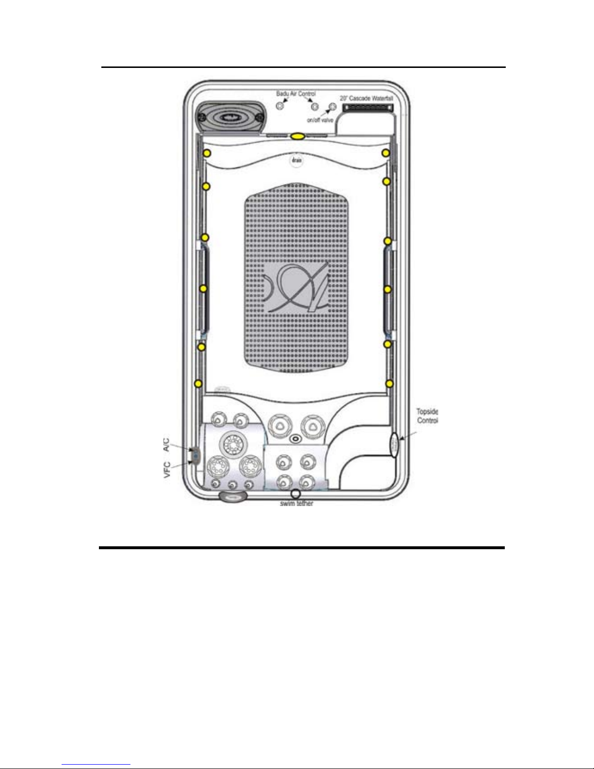
CONFIGURATION AND WATER CAPACITY
TidalFit
Volume 1715 gal 7554 l
Weight (dry/lled) 2000 / 16,303 lbs 907 / 7,395 kg
Dimensions 168x91x52in 427x231x132 cm
Control CE SWIM SPA CE SWIM SPA
Heater 4kW in.THERM 4kW in.THERM
Circulation System Hi-Flo Standard Hi-Flo Standard
Ozone CD CD
Cartridge Filter 2 2
Disposable Filter 1 1
Cascade Standard Standard
6
Page 11

7
ELECTRICAL REQUIREMENTS
AND INSTALLATION
The following information is provided for hooking up electrical supply to
your new pool. A qualied, licensed, electrician must perform this work.
Failure to follow these instructions will terminate all warranty coverage
and can cause serious injury or death.
Your 60Hz pool is preset at the factory to run on 240V with a 48 amp
input. This feature gives you the most performance out of your pool.
This will require a 240V, 60-amp GFCI
Your export 50Hz pool is preset out of factory to run 230V-240V 3 wires
30 amp max input. This product must always be connected to residual
current device (RCD) having a trip current of not more than 30 mA.
ELECTRICAL WIRING
WARNING: Your pool must be wired by a certied electrician and
according to these instructions. Failure to do so will terminate all
warranties and all listings from the independent listing facility.
1) The TidalFit requires a 240 VAC dedicated system. The pool must be
hard wired to the power supply, with no plug-in connections, extension
cords, or sharing of service.
2) The pool requires that you run 6 (10 mm²) or 8 (8.4 mm²) AWG copper wire, depending on the GFCI size. Do Not Use Aluminum Wire.
3) The power supply must have a suitable Ground Fault Circuit Interrupter (GFCI), according to Section 422-20 of the National Electrical
Code, ANSI/NFPA 70-7987 or other national installation requirement
with a residual current device (RCD) having a trip current of not more
than 30 mA. This could be used as the shut-off switch, which must be
installed in plain view of the pool. This electrical service must be readily
accessible to the pool occupants, but must not be within 5 feet of the
pool.
4) Use only non-metallic conduit and ttings when installing power to
the spa.
5) After your pool has been positioned, route lines through the knockout
on the left or right front corner of the pool.
6) Connect the power to the pool.
Page 12
8
Basic System Features and Functions
Main Board Power Requirements (60Hz)
240VAC, 48A, Class A GFCI-protected service (Circuit Breaker
rating = 60A max.)
4 wires (hot, hot, neutral, ground)
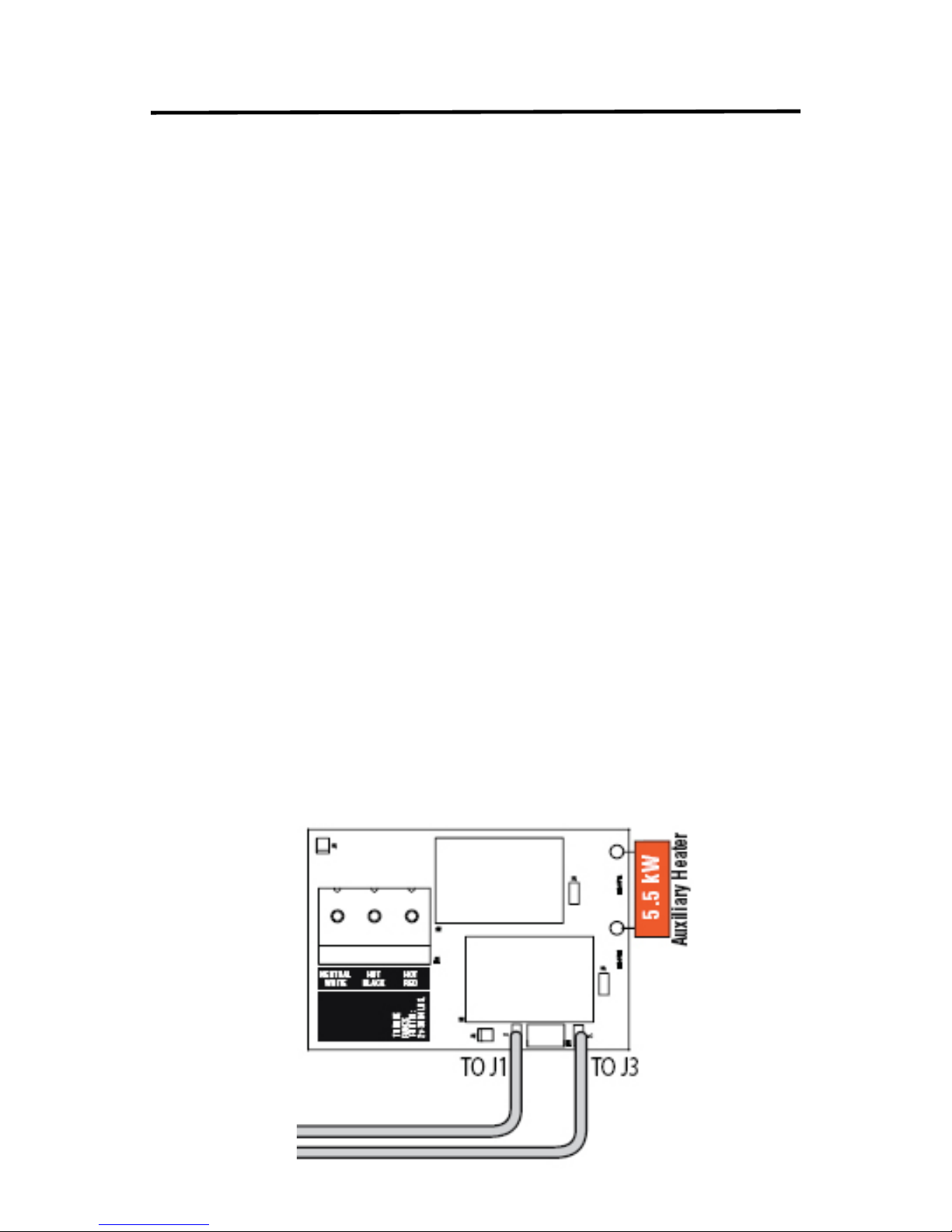
Auxiliary Heater Power Requirements (60 Hz)
240VAC, 60Hz, 24A, Class A GFCI-protected service (Circuit
Breaker rating = 30A max.)
4 wires (hot , hot, neutral, ground.)
•
•
•
•
Main Board Power Requirements (50Hz)
Single Service {3 wires (line, neutral, ground)}
230VAC, 50Hz, 1 - ,16A/32A, (Circuit Breaker rating = 20A/40A
max.
Dual Service {5 wires (line 1, neutral 1, line 2, neutral 2,
ground)}.
230 VAC,, 50Hz, 1 -, 2x 16A, Circuit Breaker rating = 20 max
each service.)
3-Phase Service [5 wires (line 1, line 2, line 3, neutral, ground)]
400VAC, 50Hz, 3N -, 16A, (Circuit Breaker rating = 20A max
each phase line.)
IMPORTANT - Service must include a neutral wire, with a line to
neutral voltage of 230VAC.
Auxiliary Heater Board Power Requirements
Single service {3 wires (line, neutral, ground)}
230VAC, 50Hz, 1 -, 24A, (Circuit Breaker rating = 30A max.)
•
•
•
•
•
•
•
•
•
Page 13
9
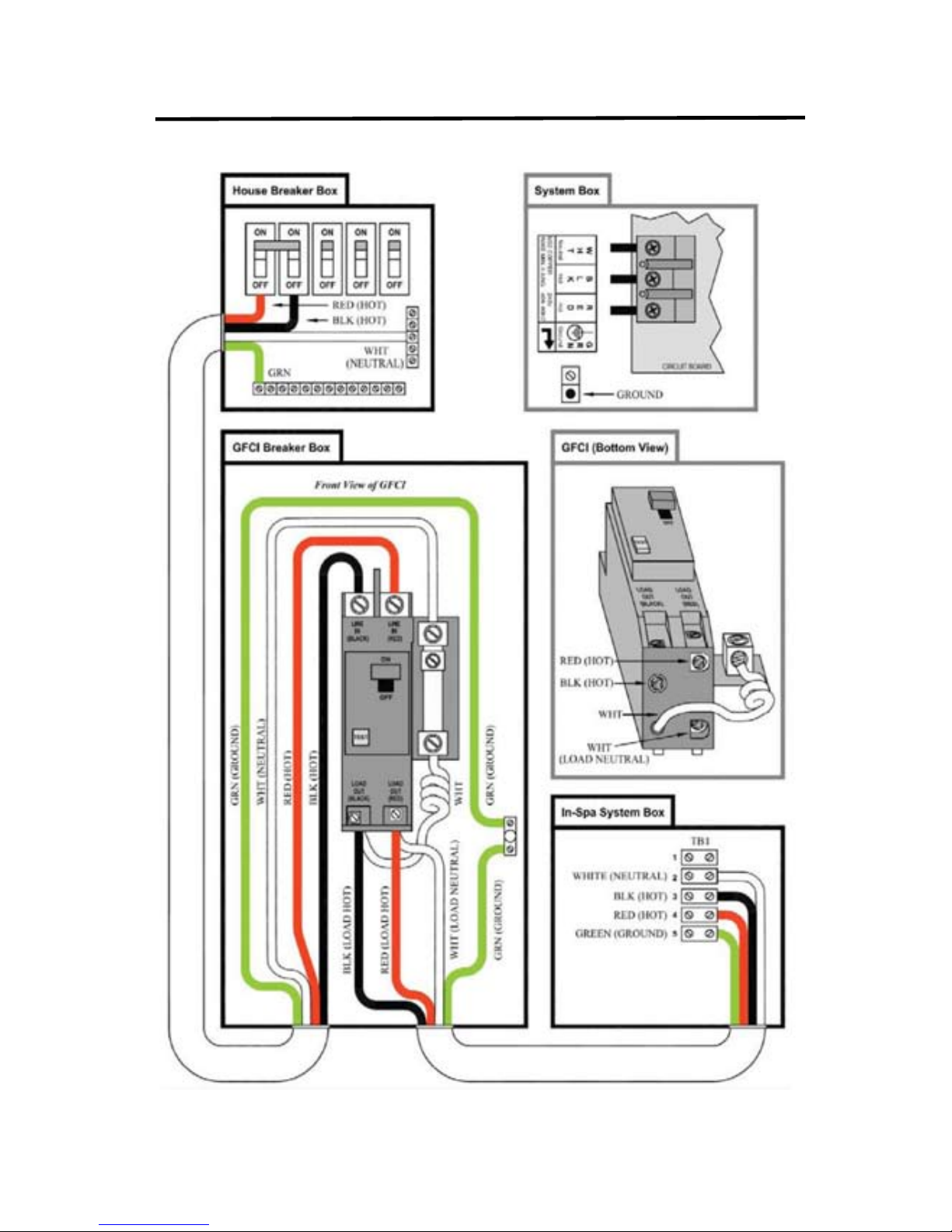
60Hz GFCI WIRING DIAGRAM
Page 14
10
1) The black and red wires from the main electrical box* must be connected to the input lugs in the GFCI.
2) The white wire from the main electrical box* must be connected to the
dedicated neutral bar inside the GFCI box.
3) The green or copper wire from the main electrical box* must be connected to a separate dedicated ground bar inside the GFCI box.
4) The red and white wires from the pool connect to the GFCI breaker
output terminals.
5) The white wire from the pool must connect to the center load terminal
ON THE GFCI BREAKER, usually behind the white pig-tail on the breaker
itself
6) The white pig-tail from the GFCI breaker must connect to the dedicated
ground bus inside the GFCI breaker box.
7) The green or copper wire from the pool must connect to the dedicated
ground bus inside the GFCI box.
*Main electrical box refers to the house distribution panel and not the
GFCI
Pack Terminal Block from GFCI
MUST BE DONE BY A CERTIFIED ELECTRICIAN
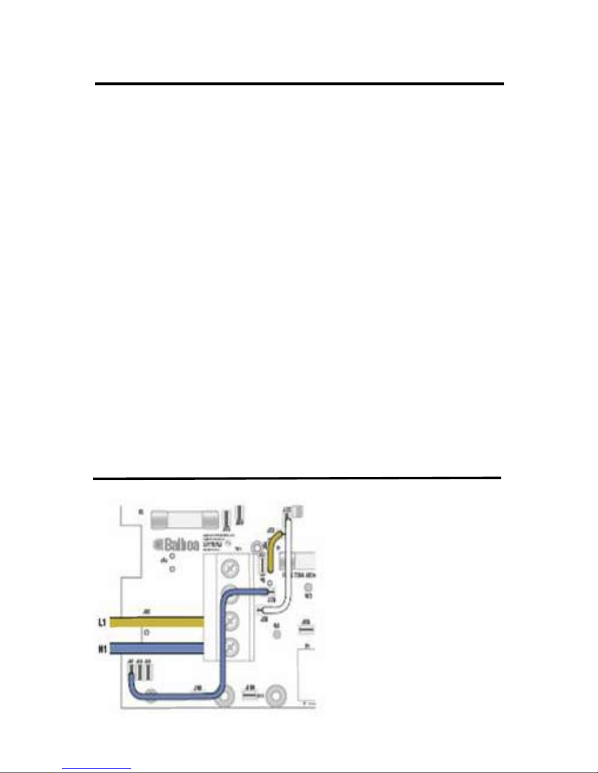
50Hz Electrical Service Conguration Options
For DIP Switch Congured
System
Single Service (1 x 16 Amp
or 1 x 32 Amp)
This option is congured and
shipped as the default.
For 1 x 32 Amp Service:
DIP Switch A2 can be ON
For 1 x 16 Amp Service.
DIP Switch A2 must be OFF
Page 15
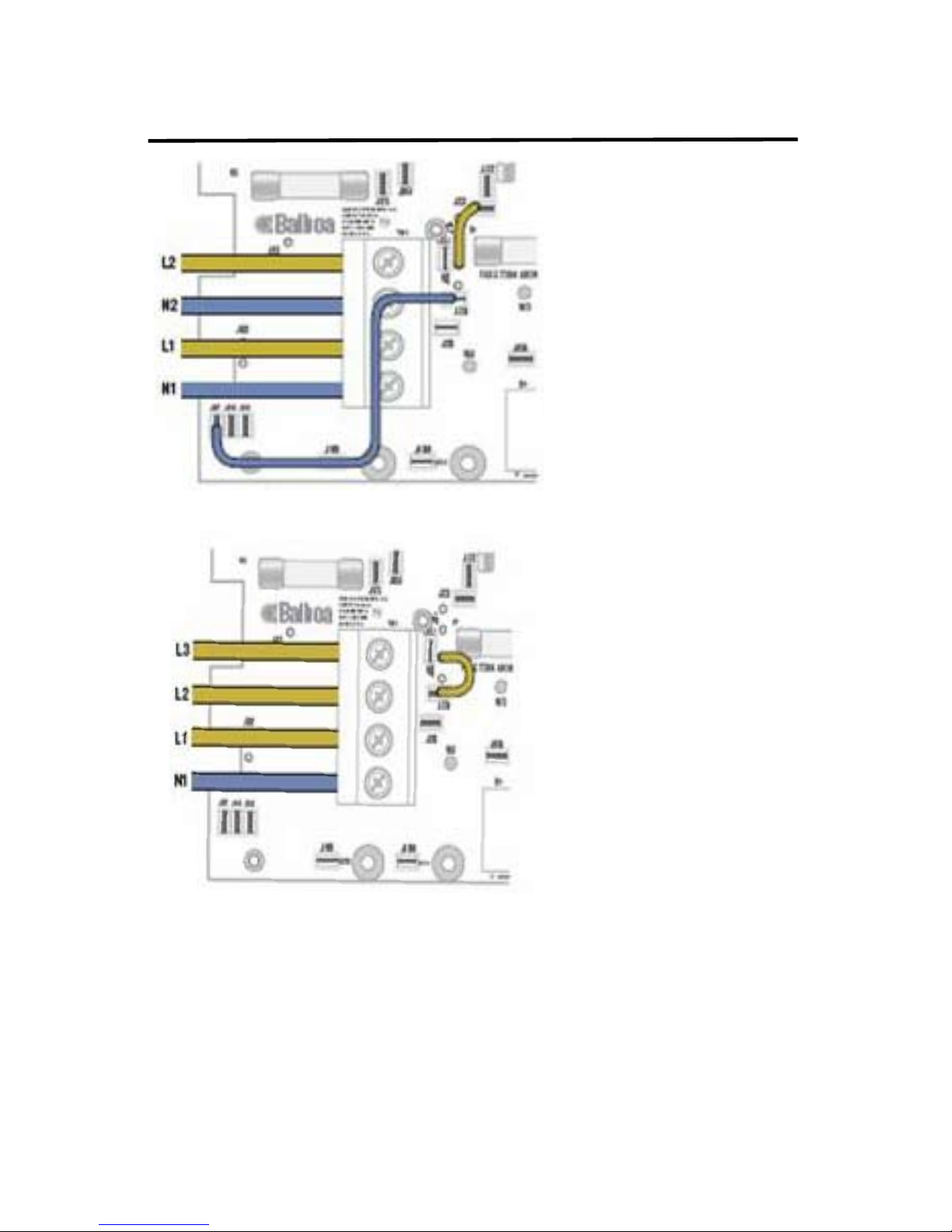
50Hz Electrical Service Conguration Options
cont’d..
11
Dual Service Option (2 x
16 Amp)
Completely remove the
white wire from J26 and
J32.
Note: J32 and J23 are
electrically identical.The
white wire may be attached to either terminal
before removal.
DIP Switch A2 must be
ON.
Completely remove the blue wire from J28
and J57.
Note: J57, J58 and J59 are electrically identical. The blue wire may be
attached to any of these terminals before removal.
Move the brown wire from J23 or J32 to J28.
DIP Switch A2 must be ON
DIP Switch A2 must be ON.
Move black wire from J27 to J53.
3 Phase Service Option
IMPORTANT - Service
MUST include a neutral
wire, with a line to neutral
voltage of 230VAC.
Completely remove the
white wire from J 26 and
J 32
Note: J32 and J23 are
electrically identical. The
white wire may be attached to either of these
terminals before removal.
Page 16

TidalFit START-UP
Please read each step of the Start-up section prior to doing the
step.
SELECTING A LOCATION
In preparation for installing your new TidalFit, you should ensure that
your chosen location meets some minimum guidelines:
1) Place your TidalFit on a surface that is large enough for the entire TidalFit to t. Consider the space needed to easily access equipment compartments and circuit breakers. Remember, all electronics must be kept dry.
2) The TidalFitl must be on a solid, level foundation. Recommended: 4
inches of cement slab that has cured for at least 72 hours. Your warranty
will be voided if the TidalFit is not properly installed. Structural damage
due to an improper foundation is not covered under warranty.
3) To avoid potential water damage to the skirt and frame, your TidalFit
should be placed on a site where it will not be in the way of water sprinklers.
(4) OUTDOOR POOL: Consider building codes, electrical and plumbing
codes, desired proximity to house, wind and sun exposure, location of
trees (falling leaves, shade), dressing area, landscaping and lighting when
selecting a location.
5) INDOOR POOL: Floor surface must have traction to prevent slipping
when wet. A oor drain is optimum. As room humidity will increase because of the spa, provide ample ventilation to prevent dry rot, mildew and
mold. Use materials that will withstand humidity. There may be a need for
cross-ventilation fans and/or dehumidiers. The spa chemicals may corrode some household metals. Provide ample room if servicing should be
needed. Strong foundational support is vital, particularly if a second-story
site is selected.
6) Ensure the equipment compartment is in a location where it will not
be damaged by water drainage. Cover the equipment compartment with
a heavy screen if rodents are a problem. Damage due to rodents is not
covered under warranty.
7) Have the pool deck installed by a knowledgeable contractor to ensure
proper support.
12
Page 17

13
8). If the TidalFit is placed on the ground, even for a short period of time,
it must be supported by stones that are at least 2 inches thick and 12
inches square. A solid foundation is recommended as soon as possible.
INSPECTION
You will want to inspect your TidalFit, prior to lling it up with water. Look
for and remove any debris in the pool tub and in the lter. Verify that
pump plugs are installed on the pumps and the pump unions are tight.
FILLING THE TidalFit WITH WATER
NOTE: DO NOT ll your TidalFit with hot water straight out of your
water heater or tap. This water may be as hot as 180ºF and will
cause damage to the surface and plumbing of the pool. This will
void your warranty. Level the pool before lling.
1) Prepare to ll the tub by removing all debris.
2) Remove the lters from your pool (see Removing, Installing and
Cleaning Filters, page 35.)
3) Place your garden hose in the center of the lter .
4) Fill the tub from the circulation pump line until water level is above
the foot-well.
Note: This will purge all the air out of the circulation pump. An air
lock can cause damage to the circulation pump and is not covered
under warranty.
5) Once the water level is lled over the foot-well, you can pull the hose
out of the lter line and continue lling the pool from the lter well.
6) Fill the pool to the bottom of the pillows. Note: DO NOT OVER-FILL
YOUR POOL!
7) With the front panel off, verify there are no leaks at the pump union.
Note: Pump unions can become loose during shipping. Verify that
there are no leaks during lling of the pool.
8) Reinstall the circulation pump screen and all lters.
Page 18

14
TURNING THE POWER ON
Turn the power to the pool on at the main circuit breaker. Verify that
your pool has no error codes. Verify that there is good water circulation
in the pool. The pumps will come on in cycles, for 1 minute each cycle.
VERIFYING WATER CIRCULATION
1) Open all the jets.
2) Press the Pump 1 key to turn the pumps on or off.
3) Make sure each seat has water ow. Note: On certain pools there is
a diverter valve. Verify where the diverter valve is located.
TESTING THE GFCI BREAKER
NOTE: The electrical service panel for your pool should be equipped
with a GFCI breaker. To avoid the risk of electrical shock, perform the
following safety test before each use of your pool.
1) Make sure the power is turned on at the electrical service panel.
2) Turn on the GFCI breaker. If the breaker stays on, it is functioning
properly.
DANGER: RISK OF ELECTRICAL SHOCK
If the GFCI breaker fails to operate as described, there is a possibility of
an electrical shock if the TidalFit is used. Shut off the power at the main
electrical service panel until the source of the problem has been identi-
ed and corrected by a licensed electrician or qualied pool technician.
Page 19

15
Tidal Fit START-UP cont...
TESTING THE GFCI BREAKER cont...
NOTE: When power is turned on, your pool is automatically programmed
to start circulating water through the circulation pump. Each pump and/
or blower will come on consecutively for approximately 1 minute to automatically purge the system. Adjust your temperature by pressing the
up button on your touch pad until the desired temperature is displayed.
This setting will allow your pool to heat to the set temperature.
CAUTION: If water is not noticeably coming from your pool jets during
the automatic purge, turn on the high speed pump. If water is still not
coming from the jets, the pump needs to be manually primed, following
the steps below.
PRIMING THE PUMP
1) Turn off power at electrical service panel.
2) Locate and loosen one of the pump plugs on each pump by turning it
counterclockwise one half of one turn.
3) Allow air to escape from ttings. When a steady stream of water ows
from the pump plug, close it by turning it clockwise until tight.
4) Turn on power at electrical service panel.
5) Check once more to make sure that water is owing from the jets during auto purge. If so, continue. If no water is coming from your spa jets,
please call your Artesian dealer for further assistance.
WATER PREPARATION
NOTE: Before putting your new pool into operation, understand that
preparing your new water is an important part of maintenance. Failure
to properly prepare your water can result in substantially decreasing
the life of the components and may void your warranty in severe cases.
Your Artesian dealer should have a start-up and maintenance kit available for you when you receive your pool.
Page 20
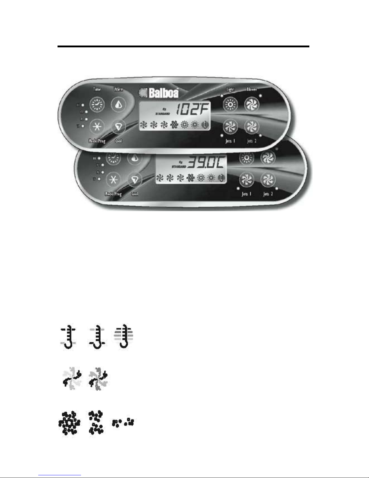
ML700 PANEL USER GUIDE
.
Initial Start-up
When your pool is rst actuated, it will go into Priming mode (after dispalying some conguration information). Please see the M-7 Installa-
tion Instruction Manual for complete instructions on Power-up and
Pump Priming. The Priming mode will last for up to 4 minutes and then
the pool will begin to heat and maintain the water temperature in the
Standard mode. You can exit Priming mode early by pressing “Warm” or
“Cool”.
Icon Legend
Heat Icon - Indicates different stages of heating.
Jets Icon - Spins fast on high speed; spins slow
On low speed
Blower Icon - Biggest in highest speed; smallest
In lowest speed.
16
Page 21

17
Time
When time hasn’t been programmed, the “TIME” icon ashes to set the
time, press “Time” then “Mode/Prog.” Use the “Warm” and “Cool” buttons
to adjust time. See previous page for more detailed instructions. (Time
settings on EL1000 and some EL2000 systems are not preserved in the
event of power loss; time will have to be reprogrammed upon each power
up.)
Setting the Time
Once the pool has been properly connected the rst time (every power
up on the EL1000 and some EL2000 systems), notice the “TIME” icon
appearing on the screen.
Then
to enter
Press
(Each press changes
the time by 1 minute)
Or
Select the hour by
pressing
Press
(Each press changes
the time by 1 minute)
Or
Select minutes by
pressing
to Exit the time setting procedure and enter
the optional lter cycle programming. (Exits
programming on EL1000 and some EL2000
systems).
Press
to exit programming.
Press
Time
Mode/prog
Warm
Mode/Prog
Cool
Mode/Prog
Time
Warm
Cool
Page 22

18
Temp Set (80ºF - 104ºF / 26.0ºC - 40.0ºC)
The last measured temperature is constantly displayed on the LCD. Your
pool’s set temperature range may vary from range shown above depending on your manufacturer’s settings
Note that the last measured spa temperature displayed is current
only when the pump has been running for at least 1 minute.
Warm/Cool
Press the “Warm” or “Cool” button once to display the set temperature.
Each time either button is pressed again, the set temperature will increase or decrease depending on which button is pressed. After three
seconds, the LCD will automatically display the last measured spa temperature.
Mode/Prog
This button is used to switch between Standard, Economy, and Sleep
modes. Press “Mode/Prog” to enter mode programming, press “Cool” to
cycle through to desired mode (LCD ashes until conrmed), then press
“Mode/Prog” to conrm selection.
Standard Mode maintains the desired temperature. Note that the last
measured pool temperature displayed is current only when the pump has
been running for at least 1 minute. The “STANDARD” icon will display
until the mode is changed.
Economy Mode heats the pool to set temperature only during lter cy-
cles. The “ECONOMY” icon will display until mode is changed.
Pressing “Jets 1” while in Economy Mode puts the pool in Standard-
In-Economy mode, which operates the same as Standard Mode, then
reverts to Economy Mode automatically after 1 hour. Both the “STAN-
DARD” and “ECONOMY” icons display in this mode. During this time,
a press of the “Mode/Prog” button will revert to Economy Mode immediately.
Sleep mode heats the spa to within 20ºF (11ºC) of the set temperature only during lter cycles. The “SLEEP” icon will display until mode
is changed.
Standby Mode
Pressing “Warm” or “Cool” then “Jets 2” will turn off all pool functions tem-
porarily. This is helpful when changing a lter. Pressing any button resets
the pool. On some systems the “Jets 1” button will control the ...
Page 23

pump in Standy Mode (“Drain Mode”). In this case, press any other button to exit. System will will revert to previous mode after 1 hour.
Jets 1
Press the “Jets 1” button once to turn pump 1 on or off, and to shift between low and high speeds if equipped. If left running, the pump will turn
off after a timeout period. The pump 1 low speed timeout on some systems may be as long as 4 hours.
On non-circ systems, the low speed of pump 1 runs when the blower or
any other pump is on. It may also activate for at least 1 minute every 30
minutes to detect the spa temperature (polling) and then to heat to the
set temperature if needed, depending upon mode. When the low speed
turns on automatically, it cannot be deactivated from the panel; however,
the high speed may be started.
Jets 2 (optional on some systems)
Press the “Jets 2” button once to turn pump 2 on or off, and to shift between low and high speeds if it is a two-speed pump. If left running, the
pump will turn off after a timeout period.
Invert
Press the “Warm” or “Cool” button, then “Blower” to change the numbers
in the display to read upside down. Repeat sequence to return the display to it’s normal right- side-up display.
Note: If your system does not have a “Blower” button, use “Jets 3” instead.
Preset Filter Cycles
On all systems, the pump and the ozone generator will run during ltration. At the start of each lter cycle, the blower will run briey on its
19
highest speed to purge the air channels. The lowest speed of any other
pumps and the mister will also run briey. On some circ systems, pump
1 may also run for the duration of the lter.
(The following is specic to all systems that are programmed according time.)
There are two lter cycles per day. The start/end times of each cycle
are programmable. To program set time as instructed above, then press
“Mode/Prog” to advance to the next setting (or to exit after the last set-
ting). Default lter cycles can vary from system to system. A common
Page 24

default is 8:00 AM to 10:00 AM and 8:00PM to 10:00 PM. Press “Time”
then “Mode/Prog” to step through the lter settings to see how they are
currently set.
Each lter cycle automatically operates the pump for the duration of the
lter cycle. The lter 1 “F1 l“ icon will light when lter 1 is running. The
lter 2 “F2 l “ icon will light when lter 2 is running.
(The following is specic to EL2000 and El1000 systems that are
programmed according to duration rather than time.)
The rst lter cycle (“day”) begins 6 minutes after the spa is powered up.
The second lter cycle (“night”) begins 12 hours later. Filter duration is
programmable for 1-12 hours (“F 1”-”F12”). The default lter duration
can vary from system to system. To program, press “Warm” or “Cool,”
then “Jets 1.” Press “Warm” or “Cool” to select the lter duration. Press
“Jets1” to select the number of lter cycles. The display will show “dn”
(both “day” and “night” cycles; “d” (day cycle only); or “n” (night cycle
only). Press “Warm” or “Cool” to adjust, then press “Jets 1” to exit the
programming mode. For continuous ltration, use “F 12” and “dn”.
Note: EL 1000 and some EL2000 are capable of being programmed by
time rather than by duration (see Preset Filter Cycles section). On EL
2000 and EL1000 systems with duration programming only, the spa pow-
ers up at 12:54, thus the rst lter cycles begins 6 minutes later at 1:00.
If you would like your spa to begin ltering at another time, you may
change the clock to align with your preferred lter time, rather than the
actual time of day.
Optional Filter Cycle Programming
You are not required to set lter cycles; however, it is an option available
to you. To change the lter cycle settings;
Press “Time” “Mode/Prog” “Mode/Prog” “Mode/Prog” within 3 seconds.
You will see the “PROGRAM”, “FILTER 1” and “START TIME” icons appear on the display.
20
Press “Warm” or “Cool” to choose the lter start time hour. Enter the hour
by pressing “Mode/Prog”. Press “Warm” or “Cool” to choose the lter
start time minutes. Each press changes the start time by 5 minutes.
Enter the minutes by pressing”Mode/Prog”.
Press “Mode/Prog” to see the “PROGRAM,” “FILTER 1 and “END TIME”
icons. Adjust the time as done above.
Press “Mode/Prog” to see the “PROGRAM,” “FILTER 2” and “START”
TIME” icons. Proceed as above.
Page 25

Press “Mode/Prog” will enter the new lter cycle times into the system
and display the current water temperature.
Pressing “Time” at any time during this programming sequence will save
the values entered up to that point and exit programming.
If you would like to select continuous ltration, set the lter 1 start and
end times to be the exact same time. In this case, the lter 2 start time
only controls when the second purge happens. Filter 2 end time will be
unavailable.
Light
Some systems are equipped with both a spa light and a ber optic light;
however, only one can be accessed by this panel. (Larger panels may be
purchased so that both the spa light and ber optic light can be utilized.)
Depending upon how your spa is equipped and congured, the “Light”
button will operate in one of three ways:
1.) Press the “Light” button to turn the spa light on and off.
21
Page 26

Freeze Protection
If the temperature sensors within the heater detect a low enough temperature, then the pump(s) automatically activate to provide freeze protection. The pump(s) and blower will run either continuously or periodically
depending on conditions.
In colder climates, an optional additional freeze sensor may be added to
protect against freeze conditions that may not be sensed by the standard
sensors. Auxiliary freeze sensor protection acts similarly except with the
temperature thresholds determined by the switch. See your dealer for
details.
Locking the Panel
Press “Time” “Jets 1” then “Warm” within 3 seconds. When locked, the
PL “PL l “ light will light. All buttons are frozen except the “Time”: button. To unlock the panel, press “Time” “Jets 1” then “Cool.”
Locking the Set Temperature
Press “Warm” or “Cool” then “Time” “Jets 1”. And “Warm” within 3 seconds to activate the lock. The TL “TL l “ light will light when the set temperature is locked.
On some systems, locking the set temperature also locks out Mode
changes.
To unlock the set temperature, press “Warm” or “Cool” then “Time,” Jets
1” and “Cool”
22
Page 27

23
No message on display.
Power has been cut off to the spa.
The control panel will be disabled until power
returns. Time of day will be preserved for 30
days with a battery back-up on EL8000 and
EL 5000 systems. EL1000 and some EL2000
systems reset the time of day on each powerup. Pool settings are preserved on all systems
“Overheat” - The pool has shutdown. On some
systems, an alarm may sound. One of the sen-
sors has detected 118ºF (approximately 47.8ºC)
at the heater.
DO NOT ENTER THE WATER. Remove the
spa cover and allow water to cool. Once the
heater has cooled, reset by pushing any button. If pool does not reset, shut off the power
to the pool and call your dealer or service
organization
“Overheat” - The pool has shutdown. One of
the sensors has detected that the pool water is
110ºF (approximately 43.3ºC).
•
•
DO NOT ENTER THE WATER. Remove the
pool cover and allow water to cool. At 107ºF
(approximately 41.7ºC), the pool should automatically reset. If pool does not reset, shut off
the power to the pool and call your dealer or
service organization
“Ice” - Potential freeze condition detected.
No action required. The pumps and the blower
will automatically activate regardless of pool
status.
Pool is shutdown. The sensor that is plugged
into the Sensor “A” jack is not working
If the problem persists, contact your dealer or
service organization. (May appear temporarily
in an overheat situation and disappear when
the heater cools).
•
•
•
Diagnostic Messages
Page 28

Diagnostic Messages cont...
Pool is shutdown. The sensor that is plugged
into the Sensor “B” jack is not working
If the problem persists, contact your dealer or
service organization. (May appear temporarily
in an overheat situation and disappear when
the heater cools).
Sensors are out of balance. If this is alternating
with the temperature, it may just be a temporary condition. If the display shows only this
message (periodically blinking), the pool is
shut down.
If the problem persists, contact your dealer or
service organization.
A substantial difference between the temperatures sensors was detected. This could indi-
cate a ow problem.
Check water level in pool. Rell if necessary. If
the water level is okay, make sure the pumps
have been primed. Press any button to reset.
Persistent low ow problems. (Displays on the
fth occurrence of the “ HFL” message within
24 hours.) Heater is shutdown, but other spa
functions continue to run normally.
Follow action required for “HFL” message.
Heating capacity of the pool will not reset automatically, you may press any button to reset.
Inadequate water detected in heater.
Check water level in pool. Rell if necessary. If
the water level is okay, make sure the pumps
have been primed. Press any button to reset.
Inadequate water detected in heater, (Displays
on third occurrence of “dr” message.) Pool is
shutdown.
•
•
•
•
•
24
Page 29

25
Diagnostic Messages cont...
Follow action required for “dr” message. Pool
will not automatically reset; you may press any
button to reset.
When your pool is rst actuated, it will go into
Priming Mode.
See the M-7 Installation Instruction Manual for
complete instructions on Power-up and Pump
Priming. The Priming mode will last for up to
4 minutes and then the pool will begin to heat
and maintain the water temperature in the
Standard mode..
Temperature unknown.
After the pump has been running for 1 minute,
the temperature will be displayed.
Temperature not current in Economy or Sleep
mode.
In Economy or Sleep mode, the pump may be
off for hours outside a lter. If you wish to see
the current pool temperature, either switch to
Standard mode or turn Jets1 on for at least a
minute.
Standby mode has been activated by pressing
a button combination on the user panel.
Press any button, except “Jets 1” to leave
Standby Mode and return to normal operation.
pH is low.
Add pH increaser according to manufacturer’s
instructions.
pH is high.
Add pH reducer according to manufacturer’s
instructions.
•
•
•
•
•
•
•
or
Page 30
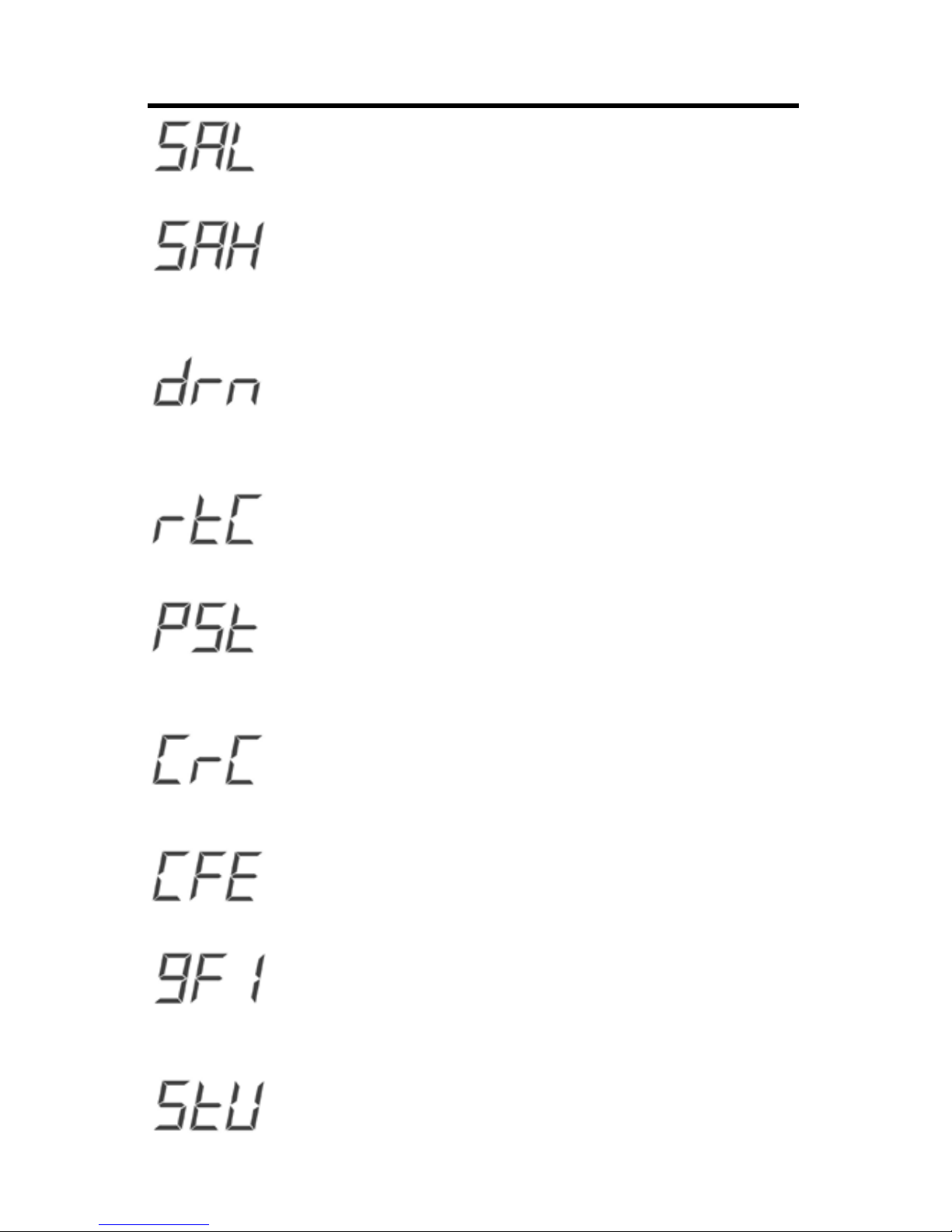
Diagnostic Messages cont...
Sanitizer is low.
Add sanitizer according to manufacturer’s
instructions.
Sanitizer is high.
Remove pool cover and allow sanitizer to dissipate.
The pump is on during Standby Mode to assist
in draining the pool.
Press “Jets 1” to turn off the pump when water
has drained (or power off the pool.).
Hardware failure.
Contact your dealer or service organization.
Hardware failure.
Contact your dealer or service organization if
message appears on more than one power up.
Firmware install problem.
Contact your dealer or service organization if
message appears on more than one power up.
Conguration error. Pool cannot start up
Contact your dealer or service organization.
Pool could not trip GFCI.
Contact your dealer or service organization .
Continued operation may be unsafe.
A pump appears to be stuck on, causing the
water temperature to creep up, possibly to
hazardous levels.
•
•
•
•
•
•
•
•
26
Page 31

27
Diagnostic Messages cont...
POWER DOWN POOL IMMEDIATELY. DO
NOT ENTER THE WATER. contact your
dealer or service organization.
A pump appears to have been stuck on the last
time spa was powered.
POWER DOWN POOL IMMEDIATELY. DO
NOT ENTER THE WATER. Contact your
dealer or service organization.
•
•
Periodic Reminder Messages...(Press the
“Mode” button to reset a displayed reminder.*)
Every 7 days.
Test and adjust pH chemical levels per manufacturer’s instructions.
Every 7 days.
Test and adust sanitizer chemical levels per
manufacturer’s instructions.
Every 30 days
Remove, clean, and reinstall lter per manufacturer’s instructions.
Every 30 days
Test and reset GFCI per manufacturer’s instructions.
Every 90 days
Drain and rell pool per manufacturer’s instructions.
Every 180 days
Clean and condition cover per manufacturer’s
instructions.
Every 180 days
Clean and condition wood per manufacturer’s
instructions
•
•
•
•
•
•
•
•
•
•
•
Page 32

Every 365 days.
Install new lter.
As needed.
Install new Mineral cartridge
•
•
Periodic Reminder Messages cont...
* User can suppress all reminders in User Preferences.
**All of these Periodic Messages can be disabled individually by the
pool manufacturer.
***Any of these frequencies may be changed by the pool manufacturer.
Note: The GFCI section does not apply on EL systems used outside
the United States. This GFCI section does not apply to GL Systems.
GFCI Protection
Your pool may be equipped with a GFCI Protection feature. If your pool
does not have this feature enabled, the GFCI Trip Test must occur to
allow proper pool function.
Within 1 to 7 days after startup, the pool will trip the GFCI to test it.
(The number of days is factory programmed.) The GFCI must be reset
once it has been tripped. After passing the GFCI Trip Test, subsequent
GFCI trips will indicate a ground default or other unsafe condition requiring the power to the pool to be shut off.
Warning: The owner should test and reset the GFCI on a regular basis
to verify it’s function
28
Page 33

29
Once the GFCI is tripped by the test, reset the GFCI and the pool will
operate normally from that point. You can verify a successful test by
navigating to the “9FC” item as described above, pressing “Jets 1” and
then pressing the “Warm” button until you see “9SP”. The code signi-
es GFCI Status - Passed.
The system will exit this menu in 30 seconds if no buttons are pressed.
GFCI Trip Test Procedure
The installer can cause the GFCI Trip Test to occur sooner by initiating
it with the following button sequence.
Press “Warm”, then “Jets 1”, then “Light.” (Each press must be within
3 seconds of the previous press.) Press the “Warm” button repeatedly
until “9FC” is displayed. Press “Jets 1” to select it. Press the “Warm”
button until “9t.n” is displayed. Press “Jets 1” to initiate the GFCI Trip
Test.
The GFCI should trip within several seconds and the pool should shut
down. If it does not, shut down the power and manually verify that a
GFCI breaker is installed and that the circuit and pool are wired correctly. Verify the function of the GFCI with it’s own test button. Restore
power to the pool and repeat the GFCI Trip Test.
Page 34
30
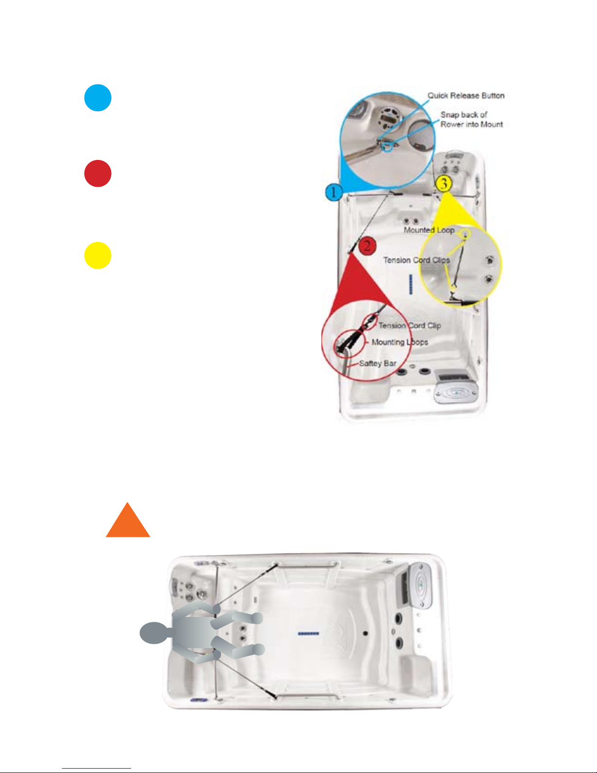
Rowing Exercise
Install First Set of Tension Cords
Use the mounting loops as a slip
knots around each safety bar.
Clip tension cord to mounting loop.
Clip tension cord to rowing bar.
Install Rowers
Press the quick release button.
Snap the back of the rowing bar
into the mount.
Install Second Set of Tension Cords
Choose a desired pair of the varying length tension cords.
Clip the tension cord to the
mounted loop.
Clip the tension cord to the row bar.
2
1
3
The tension cords are varying sizes
to compensate for different levels of
tension.
Rowing
Sit in the rowing seat and grasp the rower
handles, to begin your rowing exercise.
!
Double check the Rowers, making sure that each clip,
cord and rower is mounted securely.
Page 35
31
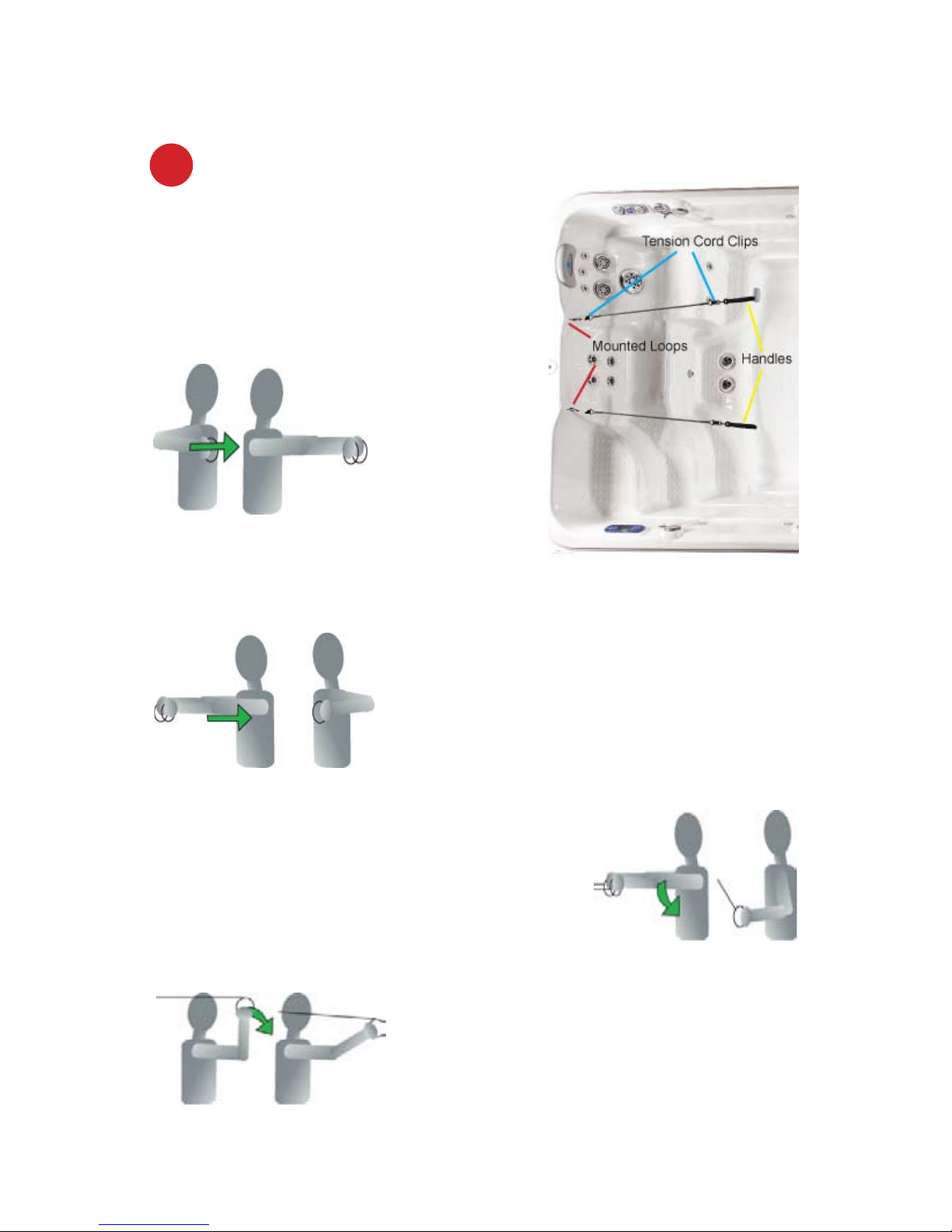
Upper Body Workouts
Install Tension Cords
Choose a desired pair of the varying
length tension cords.
Clip the tension cords to the
mounted loops.
Attach handles to the tension cords.
1
Shoulder Pull
Stand upright holding the cords in front of you
with a little bit of tension. Start with arms and
hands at chest level and outstretched in front
of you. Pull arms to your sides, keeping your
elbows at chest level.
Tricep Pull
Sitting in the seat and facing away from
the cords, position your elbows chest
level, and hands eye level. Keeping your
elbows parallel to your shoulders, pull until
your arms is outstretched in front of you.
Chest Press
Standing upright and facing
away
from the cords,
Position your
hands and
elbows at
your sides, chest level. Keeping your
elbows at chest level, push until your
arms are outstretched in front of you.
Back Pull
Stand upright holding the cords in front of
you with a little bit of tension. Start with arms
at chest height and outstretched in front of
you. Bend your arms, and pull your elbows
diagonally to your waist.
Page 36
32
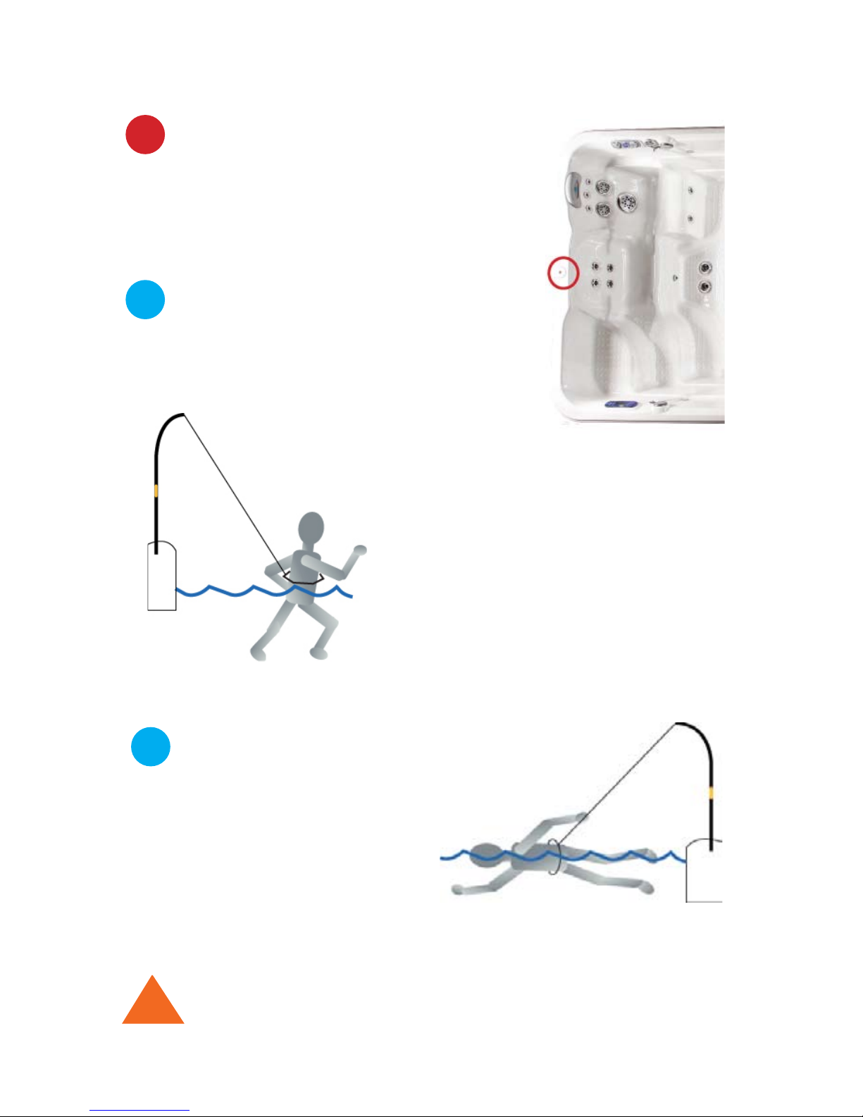
Treadmill with SuperSwim
2
1
Install Super Swim Pole
Attach the two poles together by matching
up the brass attachments and twisting until
tightened.
Place bottom of the pole into the attachment
on the lip of the pool, above the rowing seat.
Adjust nylon rope to desired length.
Treadmill
Run in place, utilizing water resistance.
Install Waist Band
Pull the stainless steel clip along the waist
band to adjust belt’s diameter.
Strap waist belt attachment to your waist
by buckling the smaller clip into the larger,
angled clip.
Swimming with Added Resistance
Practice advanced swimming
techniques and swim at a faster rate
with the waist attachment.
Advanced Swimming with SuperSwim
!
For more information on the installation and use of the SuperSwim,
please refer to the DVD.
Install Waist Band
Strap waist belt attachment
to your waist by clipping the
smaller clip into the larger
angled clip.
2
Page 37
33
MAINTAINING YOUR TidalFit
DRAINING YOUR TidalFit
Your TidalFit needs to be drained, cleaned, waxed, and relled about
every six months. More frequent water changes may be necessary if
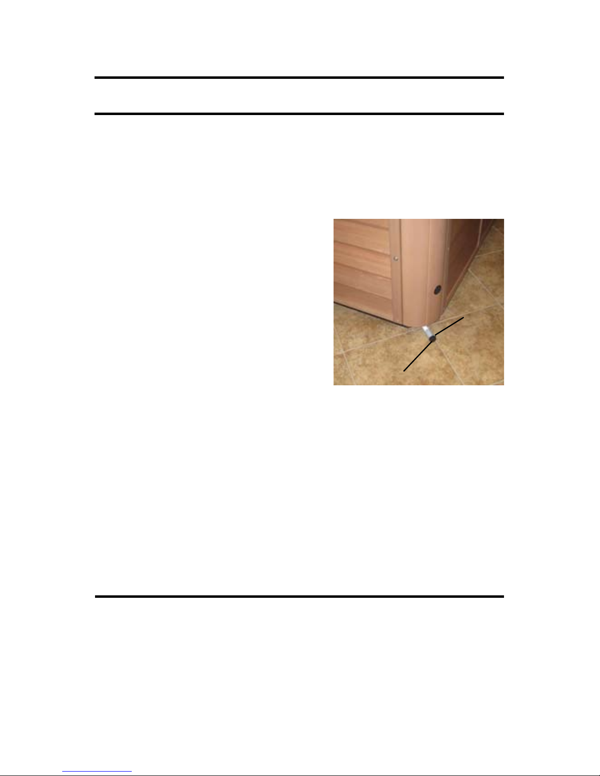
bather load is heavy. A hose bib has been provided below the left side
of your front access panel, to assist you in draining your pool.
1) Turn off the power to your pool. If you fail to turn the power off,
vital components could be damaged. Do
not leave an empty pool exposed for long
periods of time in hot, sunny weather.
2) Attach your garden hose to the hose
bib.
3) Place the other end of the hose in an
area that will accept the water capacity
of your pool.
4) Open the hose bib by turning the
valve knob counter clockwise to the full stop position.
5) Check the garden hose end to see if water is owing. If water is not
owing, check the hose for kinks. Also check to see if valve is in the
full open position.
CAUTION: The chemical content and temperature of the water will
cause damage to certain vegetation. We do not recommend that
you drain your pool onto plants or lawns. If you choose to do this,
please remove your pool cover and allow pool to cool for a minimum of 24 hours with the pool turned off.
PILLOW CARE
Remove and clean the pillows with soapy water and a soft cloth when
needed. Use a vinyl conditioner once a month. Remove pillows when
doing chemical shock treatment.
ValveKnob
Hose Bib
Page 38
34
JET CARE
We recommend that you clean your jets when you drain your pool.
However, if you do need to clean your jets in between this can be
accomplished with a full pool.
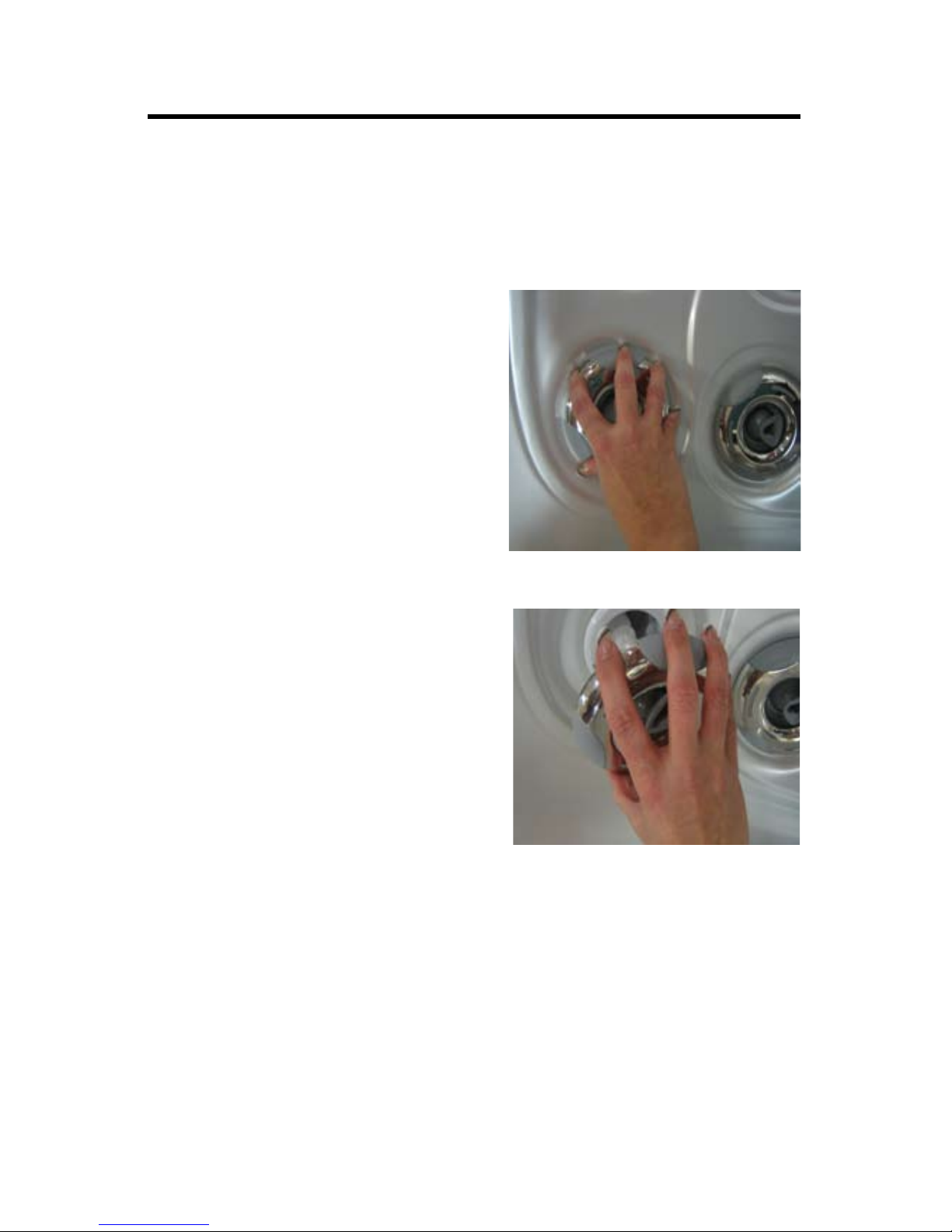
1) To remove the jet inserts turn
the jet counterclockwise to the
off position until it stops.
Continue to turn the jet past the
stop point to loosen it from the
pool. The insert will now pull out.
2) Soak jet inserts in a mixture of
1 part vinegar to two parts warm
water for 2-3 hours. Periodically
rotate the spinner nozzle to
break up residue in the jets.
4) Rinse the jet inserts under warm
water.
5) To reinstall the jets insert jet into
jet body and turn clockwise until
fully seated then tug to make
sure it is seated properly. You
can then continue to turn clock wise until it stops.
NOTE: A jet with stainless steel escutcheons can be slippery. You
can use a soft cloth or jar-opening pad to assist in removing and
installing the jet.
Page 39

MAINTAINING YOUR TidalFit cont...
REMOVING, INSTALLING AND CLEANING FILTERS
These are the steps needed to successfully replace your lters You
should replace your disposable pool lters and clean your non-disposable lters every four months.
1) Turn off all power to your pool and remove the lter lid by lifting it out
towards you.
2) Turn the lter counterclockwise and remove it from the lter well.
3) Dispose of the used lter.
4) To replace, set screen back into its place turn clockwise to fasten. DO
NOT\ over-tighten.
5) Place the new lter into position and turn clockwise to fasten. DO
NOT over-tighten.
6) Follow the directions 1) and 2) for the pleated lter cartridge. You
then rinse the lter with a garden hose and soak the lter in a mixture
of one pint of lter cleaner with 2.5 gallons of water for at least 12 hours.
The lter must be completely submerged. You then follow the directions
4) and 5) to replace the lter
WARNING: Power to your pool must be turned off prior to removing your lters. The suction at the lter is extremely strong and
can cause injury if there is no lter. NEVER run your pool without
the lters properly installed. Injury to person and damage to the
equipment can occur. Any damage to equipment due to this cir-
cumstance will not be covered under warranty.
35
Page 40

WINTERIZING YOUR TidalFit
It is not recommended that you drain your pool completely during freezing conditions. We recommend that you leave your pool full of water
with the power on to keep the tub from freezing. If you decide to drain
your pool during freezing conditions, contact your dealer for help. Con-
tact your dealer before relling a drained pool in freezing temperature.
WARNING: Damage to your pool caused by freezing is NOT covered
under warranty. Please contact your local Artesian dealer to assist you
in winterizing your pool.
REPLACING THE LIGHT BULB
1) Turn off the power at the main electrical service panel.
2) Remove front access panel.
3) Locate and remove the reector by turning it counterclockwise until
free from wall tting.
4) Remove the bulb from the holder.
5) Replace with new bulb. Your dealer has these bulbs in stock.
6) Replace the reector by screwing it clockwise back onto the wall tting.
7) Replace the front panel.
8) Turn power on at the main electrical service panel.
NOTE: The pool light bulb is not covered under warranty.
36
Page 41

37
MAINTAINING YOUR TidalFit cont...
TidalFit CABINET CARE
Your pool comes standard with a PermaWood, or faux wood, cabinet.
This cabinet requires no maintenance. You may wish to clean the cabinet with mild soap and water from time to time. If you elected to purchase your TidalFit with a wood cabinet, this cabinet is stained and
sealed with an oil based acrylic stain. The stain is formulated especially
for pool cabinet and deck applications and is resistant to ultraviolet light
damage caused by sun rays. It is also resistant to fungus and insect
damage. Your dealer carries this type of stain for your convenience, so
call your dealer when you’re ready to re-stain your cabinet. You should
re-stain your wood cabinet at least once a year, or more frequently depending on your environmental conditions.
1) Gently wash the cabinet with mild soap and water and allow to dry
completely.
2) Moisten a rag with the stain you have purchased from your dealer.
3) Apply the stain on the entire cabinet surface, wiping off any excess
stain as you are applying.
4) Allow stain to dry for a minimum of 24 hours before getting the cabinet wet.
NOTE: Do not apply any solid type nish such as shellac or varnish.
After weathering, these types of nishes will crack and/or turn yellow.
To renish the wood, you will need to completely strip the nish before
applying the new one. Use only the stain recommended by your dealer
for renishing your pool.
CLEANING YOUR Tidal Fit INTERIOR
It is important to clean the interior of your pool every time it is drained to
help preserve the sheen of your pool’s surface. However, it is important
that you do not use any abrasive cleaners or strong chemicals. Your
authorized dealer will be able to supply you with the proper solution for
your pool..
Page 42

After cleaning, make sure all residues are removed prior to lling the
pool. This will help prevent sudsing and improper chemical balance.
COVER CARE
Cleaning of your pool cover is an important part of routine maintenance.
Dirt acts as an abrasive to the vinyl topcoat, and can also cause wear to
folds, seams, and stitching. Mildew growing on damp, dirty vinyl will begin to actually root in the fabric, accelerating failure. Follow this simple
routine for cleaning, prior to application of vinyl protectant:
1) Rinse with cool water using a garden hose.
2) Spray with a gentle, non-foaming cleaner and wipe clean. Never use
laundry detergent, abrasives, alcohols, dish soaps or harsh cleaners.
These can actually remove some of the topcoat and cause premature
vinyl failure.
3) For stubborn dirt, use a non-abrasive sponge.
4) Rinse again thoroughly with water and allow to dry.
5) Repeat monthly, or as needed.
Your vinyl cover is affected by the UV in sunlight. Periodic treatment with
a liquid protectant will extend the life of your pool cover. The wrong kind
of protectant can be more harmful then no protectant at all. Keep any
product away from your pool that is labeled “ammable,” that contains
any type of oil, or that leaves a waxy coating on your cover.
Never stand or sit on the cover and never drag it over abrasive surfaces.
Lift cover only by the handles provided.
38
Page 43

39
MAINTAINING YOUR TidalFit cont...
CHEMICAL TREATMENT OF WATER
Water from your tap is ne for showers, bathing and drinking. However,
in a contained recirculating system such as in a pool, water must be
treated with chemicals. The main purpose of chemical treatment is to
keep the water sanitary and to maintain a specic balance of the water.
Proper balance ensures that the water will not cause irritation to the users or harm the spa’s components. Chemical treatment does have its
limitations. When water evaporates, chemical residues are left behind.
As the levels of the residues combine with other types of residue, such
as body oil and detergents, your water becomes increasingly difcult
to maintain. Because of this residual effect, at some point it becomes
easier and more cost-effective to drain, clean and rell your pool with
new water. We recommend that the water be changed at least every
six months. At this time you should also clean or replace your lters. If
your pool has a frequent and/or heavy bather load, it may be necessary
to drain and ll your pool more often. Refer to the section titled “Draining
your pool for instructions (page 33).
WARNING: Pool damage due to improper chemicals is not cov-
ered under warranty.
Page 44

40
WATER CHEMISTRY
CAUTION: The chemicals used to maintain the pH balance of the water
and to sanitize the water can be dangerous. Always follow these basic
guidelines when handling the chemicals:
1. Always read and follow the directions on the label, unless directed
otherwise.
2. Never mix different chemicals.
3. Do not exceed the recommended amounts of chemicals—follow the
directions on the label.
4. Keep all chemicals out of the reach of children and pets.
5. Keep containers closed tightly when not in use.
6. Never add water to the chemicals—always add the chemicals to
the water as directed.
7. Always store chemicals in a cool, dry place.
WATER TREATMENT GLOSSARY
1 - Total Alkalinity: Total Alkalinity measures the water’s ability to re-
sist uctuations in the pH level. It is measured in ppm (parts per million)
ranging from 0 - 400 or up. The optimum range for your pool water is
between 80 and 140. This can easily be measured with 3- or 5-way
test strips. With low alkalinity the pH level will be prone to dramatic
uctuations. With high alkalinity the pH becomes increasingly difcult
to adjust.
2 - pH (potential hydrogen): The pH is used as a measurement of
the active acidity, the concentration of active hydrogen molecules in the
water. pH is measured on a scale from 1 to 14, the lower numbers indicating a greater concentration of active hydrogen. While 7, halfway
between base and acid is neutral, the optimum level of acidity for a pool
is between 7.2 and 7.8.
Page 45

41
WATER CHEMISTRY cont...
WATER TREATMENT GLOSSARY cont...
The effects of low PH can be rapid sanitizer loss, eye and skin irritation,
expedited corrosion of metals, as well as staining throughout the pool.
High PH can result in cloudy water, low sanitizer efciency, as well as
eye and skin irritation.
3 - Parts per Million (PPM): The term “parts per million” will be used
frequently in the world of water care. The term simply means exactly
what it says: the coexistence of any one unlike item with a larger number
of “like” items.
4 - Sanitizers: Sanitizers are used to destroy bacteria and other germs
in the water. Only 2 sanitizers are used in spas, chlorine (Sodium Dichlor) and Bromine (Hydrotech or Lonza). Without the use of a mineral
system or an enzyme, the preferred level of sanitizer is between 2 and
3 ppm.
5 - Total Dissolved Solids (TDS): TDS is simply the measure of the
total amount of matter dissolved in the water. When this level becomes
too high, action is advised.
6 - Calcium Hardness: The measure of the amount of calcium dissolved in the water as expressed in PPM. Hard water, or water with
calcium levels over 250 PPM can cause scale formation on the surface
of the spa or the components of the spa.
7 - Total Chlorine: Total Chlorine is the sum of the free and combined
chlorines in the water. Often, water will contain a higher level of total
chlorine than available chlorine. If this is the case in your water, you
may use a non-chlorine shock (typically potassium monopersulfate) to
free up the remainder of total chlorine.
8 - Ozone: Ozone is a gas molecule that can be generated by an Ozonator, which is composed of three atoms of oxygen and used to oxidize
the water. Ozone is very useful for regenerating bromine from bromide
ions. It also acts as a supplement when used in conjunction with a sanitizer and may reduce the level of sanitizer required. You may read more
about ozone later in this section of your owner’s manual.
Page 46

42
9 - Organic Matter: These are carbon-derived substances typically
generated by living organisms. In a pool, they are most frequently introduced into the water by bathers. Enzyme products such as Spa Perfect
by Natural Chemistry are most effective at eliminating organic matter
from your body of water.
10 - Microorganisms: This term refers to tiny, living organisms such as
bacteria, protozoa, or algae.
11 - Sequestering: This term denes the action taken to remedy high
levels of metals or calcium in the water. By forming a complex that envelops materials in the water, commonly hardness ions, a sequestering
chemical prevents the ions from reacting to one another, thus forming
complex structures or solids.
12 - Shocking: Shocking is the act of hyper-chlorinating or hyperoxidizing the water. This can be accomplished with a myriad of shock
treatments, but is most commonly accomplished with Sodium Dichlor or
Potassium Monopersulfate. The former raises the sanitizer level to at
least 8 PPM, and the latter burns off chloramines or bromines. The use
of P.S., or non-chlorine shock is advantageous because you can bathe
only 15 minutes after treatment; however, oxidizing the water will not
kill the bacteria unless there is sufcient total chlorine to free up used
chlorine to actively sanitize.
13 - Bather Load: You may be asked by your pool professional what
the average bather load is, meaning, how many people enter the pool
on a daily or weekly basis.
14 - Alternative Sanitizers A group of products that sanitize pool, spa
and hot tub water, by means other than the application of chemicals to
the water. Includes such products as ultraviolet sanitizing systems, min-
eral puriers, ionizers and ozonators.
15 - Bactericide: A chemical that kills bacteria. The most common
bactericides are: chlorine, bromine, biguanide, ozone and silver. Most
algaecides, other than copper, exhibit some bactericidal properties.
16 - Balanced Water: Pool or spa water that is within the accepted
water analysis parameters for: pH, sanitizer, total alkalinity, calcium
hardness, chlorine stabilizer (chlorine pools only) and minerals. The
balancing, of the pool or spa water, helps to eliminate water chemistry
problems.
Page 47

43
WATER TREATMENT GLOSSARY cont...
17 - Chloramines: Irritating, odorous forms of combined chlorine,
formed by the reaction of chlorine with nitrogen containing waste products. Chloramines are ineffective as a pool or spa sanitizer. High levels of chloramines can cause the problems of “Red Eyes” or “Stinging
Eyes.” Usually requires a shock treatment to lower or destroy the combined chlorine level.
18 - Corona Discharge: A method for producing ozone, by utilizing
high voltage arcing to convert oxygen (O2) into ozone (O3). Refer to the
listing for Ozone for more information.
19 - Enzymes: Organic agents that hasten the natural breakdown (digestion) or decomposition of oily wastes and organic residues in pools
and spas.
20 - Hard Water: The term used to describe water that is high in calcium
or magnesium. High levels, usually over 400 PPM, can lead to clarity
and scaling problems, if not treated. Source of the calcium can be natural or can be contributed by chemicals such as calcium hypochlorite.
21 - Ions: The electrically charged state that an element assumes in
true solution. In the ionic state, ions are chemically reactive. Some
ions, such as, copper, silver and zinc, are used as sanitizers in mineral
puriers and/or ionizers.
22 - Ionizers: Equipment that sanitizes pool and spa water by providing
a low level source of copper and silver ions, as the water passes over
charged electrodes. Copper ions can provide algaecidal control. Silver
ions can provide bactericidal control. Other types of devices (mineral
puriers) work by an erosion principle and utilize copper, silver or zinc
ions. Spa ionizers often lack the copper element because the need for
algae control is not as acute as in a pool.
23 - Mineral Purier: A type of device that releases copper, silver or
zinc ions into the water at very low levels. In this ionic state, these
minerals can function in the sanitizer role and help control algae and
bacteria in pool and spa water. Mineral Puriers work on the principle
of erosion and do not require electrical components. Most include some
type of replaceable cartridge, that contains the copper, silver or zinc
materials.
Page 48

44
24 - Biguanide: The generic name for a non-chlorine, non-bromine,
sanitizer that utilizes the polymer PHMB (polyhexamethylene biguanide). It is used to totally eliminate the use of chlorine or bromine.
25 - Biolm: A slippery coating of microorganisms that can develop in
poorly sanitized pools and spas.
26 - Brominator: Feeding devices used to introduce bromine into pools
or spas. Most automatic types can be plumbed inline. Others are simple
oating varieties. All are intended to make the application of bromine
easier and more consistent.
27 - Calcium Carbonate: Crystalline deposits (scale) that can form on
all under water surfaces, if the water is excessively high in calcium hardness. High pH and high total alkalinity can worsen the problem.
28 - Oxidation: The chemical reaction by which organic matter is
“burned” or destroyed, by the action of chlorine, bromine, ozone, hydrogen peroxide or non-chlorine shock. Oxidation may cause minerals such as iron, manganese and copper to form discoloring stains and
precipitates, if not treated properly.
29 - Ozonator: A device for producing Ozone (O3), by either a UV (ultraviolet) light source or by electrical arcing (corona discharge). Used
for oxidizing and sanitizing purposes in both pools and spas.
30 - Ozone (O3): Typically produced by an Ozonator installed in a pool
or spa. Ozone (O3) is a form of oxygen (O2) and is a powerful oxidizing
agent. It is used to destroy organic waste and by-products and help in
the control of algae and bacteria. Ozone is not a stand alone sanitizer
and requires the supplementation of chlorine, bromine, minerals, or ionization.
31 - Soft Water: Water that is low in calcium and magnesium hardness.
Such water can prove to be corrosive to masonry surfaces and underwater metal parts. The calcium hardness level can be raised, to the
optimum range of 150-200 PPM, by the addition of appropriate amounts
of a calcium hardness increaser (calcium hardness).
Page 49

45
SPA CHEMICALS GLOSSARY
1 - Alkalinity Up: The total alkalinity of your pool water should
be between 80-140 PPM. A proper alkalinity will help buffer your
pool water against sudden changes in pH. Every 2.5 tablespoons
of Alkalinity Up will raise your alkalinity by 10 PPM in a pool holding 500 gallons of water.
2 - Bromine Tablets: These slow-dissolving tablets work especially well in the hot water of your pool. Keep a base of tablets
inside of an in-spa oater/feeder in order to maintain between 2
and 5 PPM. Add 2 tablets per 100 gallons of water and adjust the
oater’s opening to regulate the PPM level.
3 - Foam Gone: Foam in pools is typically caused by residue
from soap, shampoo, and cleansers. A small amount of Foam
Gone will dissipate the foam and will not affect the water balance.
Most foam removers are compatible with all sanitation programs.
4 - Liquid Filter Cleaner: Regular use of Filter Cleaner will great-
ly increase the life and performance of your lters by cutting away
grease, body oils, scale, and lotions. Clean lters also contrib-
ute to better water circulation and superior pool performance, be-
cause dirty lters can substantially impede water ow. Keeping
your lters clean with lter cleaner will also help keep your water
ltered and clear. This is accomplished by mixing one pint of lter
cleaner with 2.5 gallons of water and submerging the lters in the
mixture for at least 12 hours.
5 - Dichlor Grandular: This concentrated, stabilized, and quickdissolving chlorine granular is simple to use in your spa as a sanitizing shock treatment. The downside to Dichlor is that it will not
sustain a PPM base for long in hot water. However, as a rule of
thumb, if you treat your water after bathing with half a capful of
Dichlor, you will maintain clear and comfortable water, providing
your pH is controlled and your lters cleaned. Dichlor dissolves
quickly and leaves no residue.
6 - pH Down: If your pH level remains high, you can struggle
with scaling, cloudy water, rapid sanitizer loss, and possible skin
and eye irritation. pH Down can be purchased from your dealer
in either liquid or solid granular form. Please see your dealer for
recommended dosage.
Page 50

46
7 - pH Up: The effects of low pH can be rapid sanitizer loss, eye and
skin irritation, expedited corrosion of metals, as well as staining throughout the spa. pH up can be purchased from your dealer in either liquid or
solid granular form. Please see your dealer for recommended dosage.
8 - Metal Protect or Remover: Also called stain and scale defense,
metal protect inhibits staining and scaling in your spa. It will also prevent calcium build-up on the surfaces of your spa. Regular use will help
protect your spa surface as well as your plumbing, your pumps, and
even your heater.
9 - Spa Shock: Non-chlorine spa shock contains Potassium Monopersulfate and is an oxidizer that works well with mineral, chlorine and
bromine systems. Regular use of spa shock can substantially reduce
the need for sanitizing by up to 50% and will continually remove inorganics from the water. Best of all, you can bath in only 15 minutes after
application.
10 - Ascorbic Acid: Vitamin “C.” Can be used as an acidic reducing
agent in the removal of difcult metallic stains from underwater surfaces. Oxalic acid can be used in a similar manner.
MAINTAINING THE PROPER pH BALANCE
The pH factor is a measure of the relative acidity or alkalinity in the water. It is measured on a scale of 1 to 14. Pure water has a value of 7,
which is neutral. Any value above 7 is alkaline, and any value below 7
is acidic. You should maintain a slightly alkaline pH level, between 7.2
and 7.8, in the pool. Severe problems can occur when the pH balance is
not maintained within this range. If the pH level exceeds 7.8, dissolved
minerals can build up and clog the plumbing in the spa jet unit. If the pH
level falls below 7.2, the acid level in the water will begin to corrode the
metal parts in the spa jet unit. Also, the sanitation agents in the water
will not be effective if the pH level is not properly maintained. Damage
caused by improper pH levels is not covered under the warranty. To
maintain the proper pH level, you should test the pH of the water regularly. To test the water, purchase a pH test kit at a pool and spa supplier.
The pH reading should be between 7.2 and 7.8. If the level is too low,
add a pH increaser (usually soda ash). If the level is too high, add a pH
reducer (usually sodium bisulfate). Test the water again after ve min-
utes. See the instructions with your pH test kit for additional information
about testing and adjusting the pH.
Page 51

TidalFit Warranty
This section is a description of your warranty. Here you will nd descriptions of what is covered under your Tidal Fit warranty and what can void
your warranty. PLEASE READ THE WARRANTY THOROUGHLY. For
warranty outside USA and Canada, please refer to your countries Artesian Distributor.
Lifetime Structure Warranty
Your TidalFit carries a lifetime structure warranty. The structure is de-
ned as the berglass vessel below the exposed material nish. The
manufacturer warrants the pool against loss of water due to a defect in
the pool structure, for the lifetime of the pool. In the event of a defect
in the material and/or workmanship, the pool structure will be repaired
or replaced at the discretion of the manufacturer. THIS WARRANTY IS
ONLY GIVEN TO THE ORIGINAL OWNER, AND TERMINATES UPON
TRANSFER OF OWNERSHIP. COMMERCIAL APPLICATIONS ARE
EXCLUDED FROM THIS AND ALL WARRANTIES.
If the TidalFit structure is defective and must be replaced, it will be returned to the factory. The original, installed equipment (this includes the
frame, skirt, and all equipment) will be reinstalled. If new equipment is
desired, there will be additional charges to the customer.
If the frame and/or skirt of the TidalFit has been badly damaged, there
will be additional charges to the TidalFit owner for repairs or replacement. When a TidalFit needs to be returned to the factory for repair, the
cost of one way freight to the company will be at the TidalFit owner’s
expense. The manufacturer will not pay for removal, installation, cranes,
construction, de-construction, or any other cost associated with access,
egress, or ingress, of the TidalFit at the customer’s home. The manufacturer reserves the right to an on-site inspection by its authorized representative. In the unlikely event a shell or TidalFit must be replaced,
all warranties (shell, surface, electrical and plumbing) date back to the
original date of delivery
Seven-Year Surface Warranty
The TidalFit surface is described as the exposed material nish. The
manufacturer warrants the TidalFit surface to be free from defects in the
material and workmanship, such as blistering, cracking, or delaminating, under normal use and maintenance for a period of seven years from
the original date of delivery. THIS WARRANTY IS ONLY GIVEN TO
47
Page 52

OWNERSHIP. COMMERCIAL APPLICATIONS ARE EXCLUDED
FROM THIS AND ALL WARRANTIES. The TidalFit must be set on
a level solid surface that is sufcient to support the entire length and
width. Standard building practices must be followed. Damage caused
by failure to have a leveled and supported foundation under the TidalFit
is not covered under warranty. The manufacturer does not warrant problems associated with prolonged exposure to the sun and/or use of any
sanitization or ozone system not approved by the manufacturer. Damage to the TidalFit surface caused by leaving it uncovered and empty
of water with direct sunlight exposure will terminate this warranty. Any
alteration to any system, either electrical, plumbing, or mechanical, or
over use of chemicals, or any other problems caused by external source
are not covered under warranty. Other exclusions may apply.
Normally problems associated with material and workmanship can and
will be repaired. If the TidalFit surface is repaired, the repair is limited to
the affected area only, and there is no guarantee against discoloration
or fading. The decision to repair will be made by the manufacturer and
its eld representative after a review of the facts, pictures, or any other
data presented by the dealer or customer. In all cases, pictures of the
affected area and foundation of the TidalFit must be provided before any
decisions to repair or replace can be made. In the unlikely event a shell
or TidalFit must be replaced, all warranties ( shell, surface, electrical and
plumbing) date back to the original date of installation. If it is determined
that the surface is to be replaced, the same conditions and terms as
outlined in the shell warranty will apply.
Five-Year Electrical Warranty
The Electrical is dened as the electrical items (i.e. pumps, equipment
packs, heater, topside control, etc). The manufacturer warrants all elec-
trical equipment to be free from defect and workmanship for ve years
from date of delivery. THIS WARRANTY IS ONLY GIVEN TO THE ORIGINAL OWNER, AND TERMINATES UPON TRANSFER OF OWNERSHIP. COMMERCIAL APPLICATIONS ARE EXCLUDED FROM THIS
AND ALL WARRANTIES. The stereo, speakers, stereo power supply,
L.E.D. lighting, light bulbs, fuses, and Ozone are not included in this
warranty, but are covered under a separate warranty. Damage caused
by weather, poor water chemistry, and/or improper maintenance will not
be covered under this warranty. Alterations or replacements of components installed in the TidalFit that are not purchased and/or approved
by the manufacturer including incorrect wiring, will terminate the Tidal
Fit warranty.
48
Page 53

49
WARRANTY cont ...
Five Year Plumbing Warranty
The plumbing is described as all piping, jet bodies, valve bodies and
air controls. The manufacturer warrants all plumbing for a period of ve
years from the date of delivery. THIS WARRANTY IS ONLY GIVEN TO THE
ORIGINAL OWNER, AND TERMINATES UPON TRANSFER OF OWNERSHIP. COMMERCIAL APPLICATIONS ARE EXCLUDED FROM THIS AND
ALL WARRANTIES. Jet internals, valve handles, and other such items
are regular maintenance items. They are covered for the item only, labor
is not covered for these items. Damage caused by weather, poor water
chemistry, and/or improper maintenance will not be covered under this
warranty.
Cabinet Warranty
The TidalFit cabinet is described as the outer material encasing the TidalFit structure. The manufacturer warrants it to be free from defects
in material and/or workmanship from the date of delivery. THIS WAR-
RANTY IS ONLY GIVEN TO THE ORIGINAL OWNER, AND TERMINATES
UPON TRANSFER OF OWNERSHIP. COMMERCIAL APPLICATIONS ARE
EXCLUDED FROM THIS AND ALL WARRANTIES. This warranty does not
cover normal darkening, staining, or aging. The TidalFit cabinet requires
care and maintenance by the consumer. Damage caused by weather,
poor water chemistry, and/or improper maintenance will not be covered
under this warranty.
Two-Year Warranty on PermaWood Cabinets
PermaWood cabinets are covered under this warranty for a two-year
period.
One-Year Warranty on Red Wood Cabinets
Wood cabinets are covered for a one year period. A coat of stain should
be applied regularly to the cabinet to keep the wood in proper condition.
Page 54

Other Items Not Covered In This Warranty
Some items are not covered in this warranty. These items either have
a different warranty, or are warranted through the manufacturer of that
item.
Stereo and Stereo Components
The stereo and stereo components, including speakers, sub woofer,
power supply, wire harness, and remote control are covered for 30 days
from the date of delivery. This warranty does not cover damage to a stereo or stereo component from abuse, poor reception, or damage caused
by putting a wet CD into the stereo. If a stereo is replaced under this
warranty, the manufacturer reserves the right to replace the unit with
another like unit, but not necessarily the same stereo manufacturer. No
spa will be replaced for a failed stereo. The stereo does not affect the
performance of the spa.
Ozonator
The ozonator is covered for one year from the date of delivery.
TidalFit Cover
The cover manufacturer for TidalFit warrants the cover for one year.
Do not return the TidalFit cover to the manufacturer. This will delay the
replacement or repair of the cover. The TidalFit manufacturer is not responsible for lost covers.
L.E.D. Lighting
The L.E.D. lighting is guaranteed to work upon delivery. There is no warranty covering the L.E.D, lighting.
Performance
In the event of any defect covered by this LIMITED warranty, a May
Manufacturing LLC, authorized agent will correct such defect within the
terms and conditions contained herein. There will be no charge for parts
or labor within the above terms. However, travel charges that occur will
not be covered under terms and conditions by the warranty. If it is determined by May Manufacturing LLC that the repair of the product is not
feasible, a replacement pool equal to the value of the original purchase
price will be provided. Cost for removal of the defective TidalFit and
delivery and installation of the replacement is the responsibility of the
homeowner and will not under any circumstances be covered by May
Manufacturing LLC.
50
Page 55

51
WARRANTY cont...
Limitations
This warranty is void if the TidalFit has been subjected to alteration,
misuse, or repairs have been performed by anyone other than an au-
thorized agent of May Manufacturing LLC. Misuse or abuse is dened
as: use of the TidalFit in a nonresidential application, water temperature
outside the range of 32º F to 110º F, damage caused by clogged or dirty
lter cartridges, damage to the TidalFit from an absence of a hard cover,
damage to components from improper pH, use of any type of acid, or
from chemical imbalance. ACTS OF NATURE are not covered under
this warranty.
Disclaimer
May Manufacturing LLC, or its agent shall not be liable for any injury,
cost or other damage, whether incidential or consequential, arising out
of any defect covered by the LIMITED WARRANTY. The liability of May
Manufacturing LLC under this LIMITED WARRANTY shall not exceed
the original amount paid for the pool.
Legal Remedies
This LIMITED WARRANTY gives specic rights, and other rights that
may apply and will vary from state to state.
What is Not Covered Under Your Warranty
The following is a general overview of non-warranty items and work.
This is not an all-inclusive list.
Diagnosis of TidalFit Problems
Fuses
Light Bulbs of Any Kind
Removing TidalFit from a Structure
Pillows
Filters
Chemical Misuse / Damage
Filter Lids
Any Part not Purchased from your dealer
Jet Inserts
Valve Handles
Pump Seals
Page 56

52
Draining and lling the TidalFit
Acts of Nature
Travel Charges
Cabinet Screws
Incorrect Wiring
Shipping Charges
Any alteration of the TidalFit that has not been pre-authorized by the
manufacturer will void all warranties. If the manufacturer approves an
alteration, verify that this alteration is covered under warranty. Damage caused by moving a pool that is blocked in or that has been
recessed, along with additional charges for labor, is not covered by
this warranty.
Page 57
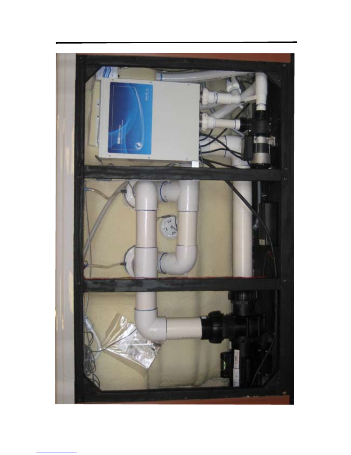
INTERIOR SPA DIAGRAM
53
Page 58

ARTESIAN SPAS
Attn: Customer Care Department
4720 N. Lamb Blvd.
Las Vegas, NV 89115
__________________________
__________________________
__________________________
Please do not send products or
other correspondence to the
address below.
Place
Stamp
Here
Page 59

Mr Ms.
Name__________________________________________________________________________________
Address________________________________________________________________________________
City_____________________________________________ State _____________________ Zip__________
Phone Number___________________________________________________________________________
Date of Installation_____________________________ Spa Serial Number___________________________
Spa Model ______________________________________________________________________________
Your Dealers Name and Location_____________________________________________________________
What other spa brands did you consider buying?________________________________________________
Optional Questions
How many people are in your household?______________________________________________________
What is your age bracket? 25-30 31-40 41-50 51-60 61-70 71+
What is your reason for purchasing a spa? Health Benets Stress Relief Relaxation
Other: __________________________________________________________________________________
 Loading...