

Page 1
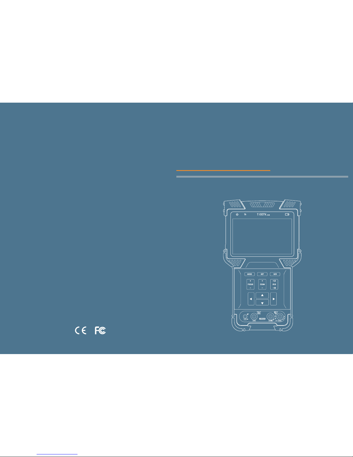
User Manual
HD COMBINE TESTER
Page 2

HD COMBINE TESTER User Manual HD COMBINE TESTER User Manual
1. Safety Information……………………………………………………………………
2. HD Combine Tester Introductions…………………………………………………
2.1 General Introduction……………………………………………………………………
2.2 Product Highlights……………………………………………………………………
2.3 Product Functions……………………………………………………………………
2.4 Accessories……………………………………………………………………………
2.5 Device Portions and Parts……………………………………………………………
3. Operation Instructions………………………………………………………………
3.1 Installing and Recharging the Battery………………………………………………
3.2 Lanyard Wearing………………………………………………………………………
3.3 Basic Starting Instruction……………………………………………………………
3.4 ONVIF Test……………………………………………………………………………
3.4.1 ONVIF Test Step 1: Ethernet and IP Test………………………………………
3.4.2 ONVIF Test Step 2: Discovering Cameras………………………………………
3.4.3 ONVIF Video Test…………………………………………………………………
3.5 SD Analog Video test and HD Coaxial PTZ Control………………………………
3.5.1 Connecting to Analog Camera……………………………………………………
3.5.2 Analog Video Test…………………………………………………………………
3.5.3 Full Screen and Portion Display of Analog Video Image………………………
3.5.4 Analog Video, Analog HD video capture and Video recording…………………
3.5.5 HD Coaxial PTZ Control…………………………………………………………
3.5.6 RS485 PTZ Control………………………………………………………………
3.6 Analog Video Generator………………………………………………………………
3.6.1 Analog Video Generator Screen……………………………………………………
3.6.2 Connection of Analog Video Generator……………………………………………
3.7 RJ45 Cable TDR Test *………………………………………………………………
3.8 Network Analysis ( Network Tools )…………………………………………………
3.8.1 Ethernet Sniff Operation……………………………………………………………
3.8.2 List Sub-Net Function Operation……………………………………………………
3.8.3 Ping function description, use method and result saving…………………………
3.9 Record Playback ………………………………………………………………………
3.10 Digital Multimeter * …………………………………………………………………
3.11 Data Monitor…………………………………………………………………………
3.12 Device Setup…………………………………………………………………………
3.13 Audio Test……………………………………………………………………………
3.14 Powering POE Powered Devices…………………………………………………
4. Specifications…………………………………………………………………………
01
02
02
02
03
04
05
09
09
10
10
11
11
16
21
25
25
26
27
27
28
29
30
30
31
31
33
34
35
35
38
41
51
52
56
56
57
Table of Contents
*Available on certain models
Page 3

1. Safety Information
When using the instrument, be sure to comply with local electrical rules. Avoid
hospitals, gas stations, and other places where electrical use is not allowed.
When using the instrument, please use the original accessories to avoid damage
caused by the use of unauthorized accessories.
Supplied accessories are only for usage by the intended equipment. Please do not
use them for other purposes to avoiding malfunctions or unpredictable accidents.
Do not expose the product to rain or moisture. This can cause performance degradation
or damage.
Do not allow the instrument to be exposed to or come in direct contact with dust or
liquid.
During the transportation and usage of the device, avoid violent collision and shock.
Otherwise, the product may not work properly due to damage of the components.
While charging the device, please do not leave it unattended. If the battery becomes
too hot, users should cut off power immediately. Charging time should be no more
than 8 hours.
Do not use in high humidity areas. If the equipment gets wet, the battery, power
cable, and all other cables should be disconnected immediately.
Do not use in environments containing flammable gases.
Do not attempt to disassemble the instrument. There are no user-serviceable parts
inside. If users feel that disassembly is necessary, they should contact our technical
department.
Do not use in environments with strong electromagnetic interference.
◆
◆
◆
◆
◆
◆
◆
◆
◆
◆
◆
2.1 General Introduction
This device is designed for video surveillance installation and maintenance. It can be
applied to analog SD video, analog HD video, HD IP CCTV systems, RS485 PTZ control
testing, IP camera testing, Ethernet testing, TDR cable testing*, video screen shots,
video recording, playback, and other functions, and combined with analog camera testing.
This device is powerful, easy to carry, very suitable for video security engineering
installation and the maintenance of front-end camera equipment. It greatly improves
engineering and installation efficiency, reducing the cost of maintenance.
2. HD Combine Tester Introductions
Support for traditional analog SD video systems, analog HD video systems, and IP
HD systems in one device.
Step-by-step testing guide allows you to locate faults quickly.
Highly compatible with ONVIF protocols.
Ergonomic, portable design and single-handed operation.
On-screen operation tips.
POE power supply, PD power accept, and 12V/2A power output.
Dual 1000M network ports, supports packet loss detection, data flow monitor, etc.
4.0 inch IPS Display with 800 * 480 resolution and 16.7M Colors.
Flip keyboard input.
Replaceable lithium-ion polymer battery, battery life of 10 hours.
Rubber protection layer.
Dual LED torch light.
◇
◇
◇
◇
◇
◇
◇
◇
◇
◇
◇
◇
1
2
*Available on certain models
HD COMBINE TESTER User Manual HD COMBINE TESTER User Manual
2.2 Product Highlights
Page 4

3
4
2.3 Product Functions
2.3.1 POE power and POE Powered, 12V/2A Output.
This function can supply POE ( 48V, 25.5W max ) or 12V/2A temporary power for
camera.
2.3.2 ONVIF Test
This function is a step-by-step guide for network camera testing.
Step 1. Testing Ethernet connection, IP settings, DHCP request, and DHCP service.
Step 2. Discovering camera, and showing a snapshot from selected camera.
Step 3. Display camera video and controlling PTZ.
The user can continue to adjust camera settings, take snapshots of videos or record
video.
2.3.3 Analog video testing function and Coaxial PTZ control
This function can display the video image which input via BNC connector. And it also can
identify SD and HD analog signal. Besides, This function displays the TV format of
image, resolutions, and other information when the image is displayed.
HD Analog testing function can support image resolutions: 720p25fps, 720p30fps,
720p50fps, 720p60fps, 1080p25fps, 1080p30fps.
This device also support Coaxial PTZ protocol, not only display image, but also support
PTZ control Simultaneously
2.3.4 RS485 PTZ Control
This function supports RS485 PTZ control, this tester supports over 30 PTZ protocols.
This function allows RS485 PTZ control from a RS485 connector.
2.3.5 Analog Video Generator
This function generates analog video signals. It can be used to test analog transmission
routes, recorders, etc. The input video signal is also showed on the screen, allowing
users to compare the input video to the output video. The generated video can be
PAL/NTSC format and support the EBU color bar, PM5544.
2.3.6 Video Snapshot, Recording and Playback
Under the condition of video play via ONVIF testing and analog video testing (including
SD and HD), this function can take snapshot and recording. And under the condition of
recording play back, it can display the snapshot and the recording video which was
saved before.
2.3.7 Data Monitor
This function can collect data via RS485. User can analysis the data according to the
request.
2.3.8 Audio Test
This function allows users to test front end microphones or other audio sources.
1. Tester device x1
2. Lanyard x1
3. Battery x1
4. Battery Cover x1
5. Tool Bag x1
6. POE Power Injector x1
7. Network Cable x1
8. BNC Cable x1
9. RS485 Cable x1
10. 12V Power Output Cable x1
11. Audio Cable x1
12. Mini USB Cable x1
13. Screen Protector Film x1
2.4 Accessories
HD COMBINE TESTER User Manual HD COMBINE TESTER User Manual
Page 5

6
5
3
4
6
8
10
14
11
1
5
7
9
12
13
18
2
2.5 Device Portions and Parts
Flip
Keyboard
Power Indicator: Lights up when power on
Data Transmission Indicator: Red light flashes when data is be-
ing transferred
Charge Indicator: Red when charging, off when fully charged
Battery Level Icon: Indicates battery level
Displays current function mode and system time
Displays various user interface menus or videos
Provides improved handling and extra protection when dropping
the device (non-replaceable)
Switches on/off full screen video display
Function Select Key: Click to bring up function select menu. Click
multiple times or use arrow keys to select desired function
Setting Button: Brings up settings menu for various functions
Arrow Keys: Navigating menus, altering settings, pan/tilt cameras.
Controls PTZ focus and other functions according to on screen tips
Controls PTZ zoom and other function according to on screen tips
Controls PTZ Iris and other function according to on screen tips.
When altering settings, use √ to confirm changes and × to cancel.
Open the internal flip keyboard to input characters numbers or symbols.
Switches between input areas
Switch character capitalization lock
Lights up green when caps lock is on
Switches between letters and symbols
Lights up red when in symbol mode
1
2
3
4
5
6
7
8
9
10
11
12
13
14
15
16
17
18
19
20
Title Bar
Display Area
Rubber Pro-
tection Layer
Internal Flip
Keyboard
TAB Key
CAPS
CAPS Indicator
SYMBOL Key
SYMBOL
Indicator
Flip Keyboard
20
15
HD COMBINE TESTER User Manual HD COMBINE TESTER User Manual
16 17 19
Page 6
7
8
3
1
11
10
7
6
1
4
9
8
5
2
12
14
13
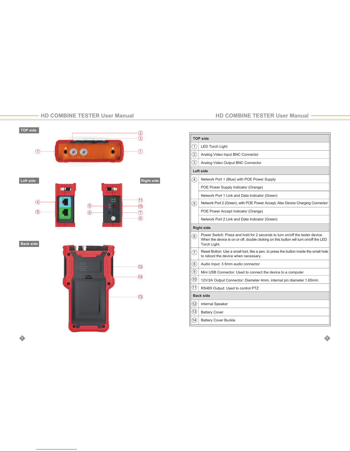
TOP side
Left side
Back side
Right side
LED Torch Light
Analog Video Input BNC Connector
Analog Video Output BNC Connector
1
2
3
6
7
8
9
10
11
12
13
14
4
Network Port 1 (Blue) with POE Power Supply
POE Power Supply Indicator (Orange)
Network Port 1 Link and Data Indicator (Green)
5
Network Port 2 (Green), with POE Power Accept; Also Device Charging Connector
POE Power Accept Indicator (Orange)
Network Port 2 Link and Data Indicator (Green)
Reset Button: Use a small tool, like a pen, to press the button inside the small hole
to reboot the device when necessary.
Audio Input: 3.5mm audio connector
Mini USB Connector: Used to connect the device to a computer
12V/2A Output Connector: Diameter 4mm, internal pin diameter 1.65mm
RS485 Output: Used to control PTZ
Power Switch: Press and hold for 2 seconds to turn on/off the tester device.
When the device is on or off, double clicking on this button will turn on/off the LED
Torch Light.
Internal Speaker
Battery Cover
Battery Cover Buckle
TOP side
Left side
Right side
Back side
HD COMBINE TESTER User Manual HD COMBINE TESTER User Manual
Page 7
9
10
3.1 Installing and Recharging the Battery
The tester device uses a rechargeable lithium-ion polymer battery. To ensure safety
when transporting, ensure the battery is disconnected from the tester deice. The device
may leave the factory with one of the following two battery placements:
1. The battery is placed inside tester and insulated from the circuit with a thin, plastic
sheet. In this case, the user should open the battery cover, take out the battery, remove
the plastic sheet, then put the battery back in, and put the battery cover back on.
2. The battery is placed outside the tester. In this case, the user should open the battery
cover, put in battery, and put the battery cover back on.
When the battery is properly placed in the device for the first time, the tester will
automatically turn on.
If battery level is too low, the charge indicator will flash 3 times, and the device won’t turn
on.
When recharging internal battery, please use the provided POE injector and RJ45 cable.
Connect the POE injector data/power-out connector to network port 2 (green) using the
RJ45 cable, then plug in city power. Network port 2 (orange) lights up when the internal
battery is recharging.
3. Operation Instructions
Due to calculation deviation or other reason, the battery level can be as low as 90% when the
charge light turns off. Users can ensure their battery is fully charged by extending the charge
time for up to 60 minutes.
Do not use a non-standard POE power supply to charge the battery. This can destroy the
tester.
The tester uses a lithium-ion polymer battery, which does not have a memory effect. Users can
recharge the battery whenever they want.
When recharging, the red battery icon ( ) lights up. When the battery is fully charged, the
light turns off.
The battery can also be charged using a POE switch or other POE power sources that meet the
802.3af / 802.3at standard.
3.2 Lanyard Wearing
Users can choose to install the lanyard. The lanyard can help handling the device,
prevent dropping the device, avoid damage to the device, and prevent loss.
To install lanyard, put one end of the lanyard through the hole at the head of the
device, turn back and go through the tri-glide button. Tighten the lanyard and confirm
that it is locked.
3.3 Basic Starting Instruction
3.3.1 Turning the Device On and Off
In either on or off status, click twice quickly to turn on or off LED torch light.
3.3.2 Using the Head Side Torch Light
The head side LED is a high-brightness LED. When opening the LED lighting, do not look
directly in order to avoid visual injury or cause other accidents.
◆
◆
◆
◆
To turn on the device, press and hold for more than 2 seconds. The power icon
will light up green when the device is turned on.
To turn off the device, press and hold more than 2 seconds, device will be turned
off. Users can also setup the idle auto power off function.
When the device is on, press the key to switch to the function select menu.
Press multiple times or use the arrow keys to select a function.
Select the function, press the direction key, you can enter the corresponding
function.
HD COMBINE TESTER User Manual HD COMBINE TESTER User Manual
Page 8

11
12
3.4 ONVIF Test
The ONVIF test function is designed to act as a 3 step trouble shooting guide. It
combines Ethernet tests, IP settings, camera discovery, camera authorization, video
display, PTZ control, camera settings, and more.
Press the key to enter function select and select the ONVIF TEST function. Wait
2 seconds or press the key. This will enter ONVIF Test Step 1.
3.4.1 ONVIF Test Step 1: Ethernet and IP Test
A. User Interface
On this interface, blue bar is for network port 1 status information; green bar is for
network port 2. The gray bar is IP test information.
The bottom light blue bar is the operate tips.
Within the network port status bar:
1 Link Speed of Corresponding Port
When it is gray and the text reads “link down”, means no network connection.
When this icon is white, and the text is digits and characters, 10M/100M/1000M is
the link speed, “FD” means full duplex mode, “HD” means half duplex mode.
The link speed can also be observed via the icon itself.
2 Ethernet Data Flow Monitor
This icon shows the current Ethernet traffic flow.
← is the outgoing data flow in b/s, kb/s, and mb/s.
→ is the incoming data flow in b/s, kb/s, and mb/s.
3 Packet Loss Monitor
This icon is the packet transfer loss status. The displayed data shows the success
rate. Normally this number is 100%.
The color of this icon color differs according to the success rate, as shown in the
table below:
4 POE Power Supply Status
This icon is for network port 1, indicating the POE power output status.
The first line of text is output mode:
12V: The device is outputting 12V and detecting PD at the same time.
PD. CLAS: This shows the classification of the remote POE device.
PSE 48V: The remote POE device is being powered.
The second line of text shows the output power in watts. When outputting power, the
actual power consumption is decided by the remote device. The tester has a max
power limit. When the remote device requires more power than max power, the
output will terminate automatically.
5 POE Power Accept Status
This icon applies to network port 2, indicating the POE power acceptance status.
The text displays the powering voltage.
6 IP Test Information ( gray bar )
The gray bar is the IP test information.
The IP setting has 3 modes: Static IP, DHCP request, and DHCP server.
1
2
4
3
5
6
RATE
Color
No Link
gray
100%
green
9
≥95%
orange
<95%
red
HD COMBINE TESTER User Manual HD COMBINE TESTER User Manual
Page 9
13
14
B. Operation
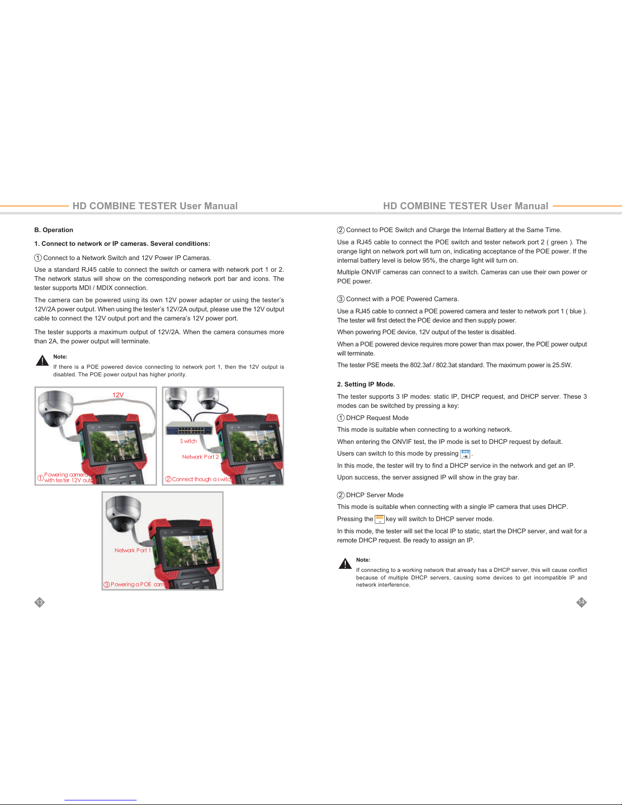
1. Connect to network or IP cameras. Several conditions:
1 Connect to a Network Switch and 12V Power IP Cameras.
Use a standard RJ45 cable to connect the switch or camera with network port 1 or 2.
The network status will show on the corresponding network port bar and icons. The
tester supports MDI / MDIX connection.
The camera can be powered using its own 12V power adapter or using the tester’s
12V/2A power output. When using the tester’s 12V/2A output, please use the 12V output
cable to connect the 12V output port and the camera’s 12V power port.
The tester supports a maximum output of 12V/2A. When the camera consumes more
than 2A, the power output will terminate.
2 Connect to POE Switch and Charge the Internal Battery at the Same Time.
Use a RJ45 cable to connect the POE switch and tester network port 2 ( green ). The
orange light on network port will turn on, indicating acceptance of the POE power. If the
internal battery level is below 95%, the charge light will turn on.
Multiple ONVIF cameras can connect to a switch. Cameras can use their own power or
POE power.
3 Connect with a POE Powered Camera.
Use a RJ45 cable to connect a POE powered camera and tester to network port 1 ( blue ).
The tester will first detect the POE device and then supply power.
When powering POE device, 12V output of the tester is disabled.
When a POE powered device requires more power than max power, the POE power output
will terminate.
The tester PSE meets the 802.3af / 802.3at standard. The maximum power is 25.5W.
2. Setting IP Mode.
The tester supports 3 IP modes: static IP, DHCP request, and DHCP server. These 3
modes can be switched by pressing a key:
1 DHCP Request Mode
This mode is suitable when connecting to a working network.
When entering the ONVIF test, the IP mode is set to DHCP request by default.
Users can switch to this mode by pressing .
In this mode, the tester will try to find a DHCP service in the network and get an IP.
Upon success, the server assigned IP will show in the gray bar.
2 DHCP Server Mode
This mode is suitable when connecting with a single IP camera that uses DHCP.
Pressing the key will switch to DHCP server mode.
In this mode, the tester will set the local IP to static, start the DHCP server, and wait for a
remote DHCP request. Be ready to assign an IP.
Note:
If there is a POE powered device connecting to network port 1, then the 12V output is
disabled. The POE power output has higher priority.
Note:
If connecting to a working network that already has a DHCP server, this will cause conflict
because of multiple DHCP servers, causing some devices to get incompatible IP and
network interference.
12V
%9 9
%9 9
C
E
92
9
9 9 2
92
HD COMBINE TESTER User Manual HD COMBINE TESTER User Manual
Page 10
16
15
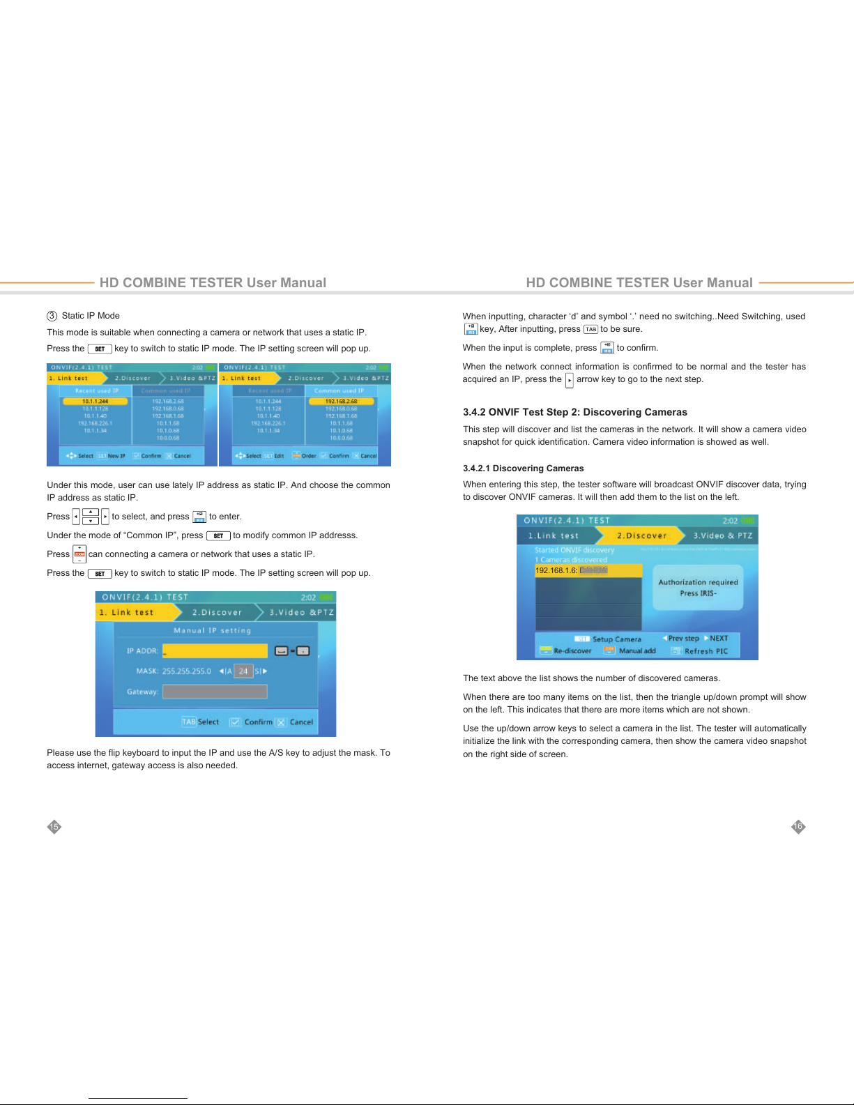
3 Static IP Mode
This mode is suitable when connecting a camera or network that uses a static IP.
Press the key to switch to static IP mode. The IP setting screen will pop up.
Under this mode, user can use lately IP address as static IP. And choose the common
IP address as static IP.
Press to select, and press to enter.
Under the mode of “Common IP”, press to modify common IP addresss.
Press can connecting a camera or network that uses a static IP.
Press the key to switch to static IP mode. The IP setting screen will pop up.
Please use the flip keyboard to input the IP and use the A/S key to adjust the mask. To
access internet, gateway access is also needed.
When inputting, character ‘d’ and symbol ‘.’ need no switching..Need Switching, used
key, After inputting, press to be sure.
When the input is complete, press to confirm.
When the network connect information is confirmed to be normal and the tester has
acquired an IP, press the arrow key to go to the next step.
3.4.2 ONVIF Test Step 2: Discovering Cameras
This step will discover and list the cameras in the network. It will show a camera video
snapshot for quick identification. Camera video information is showed as well.
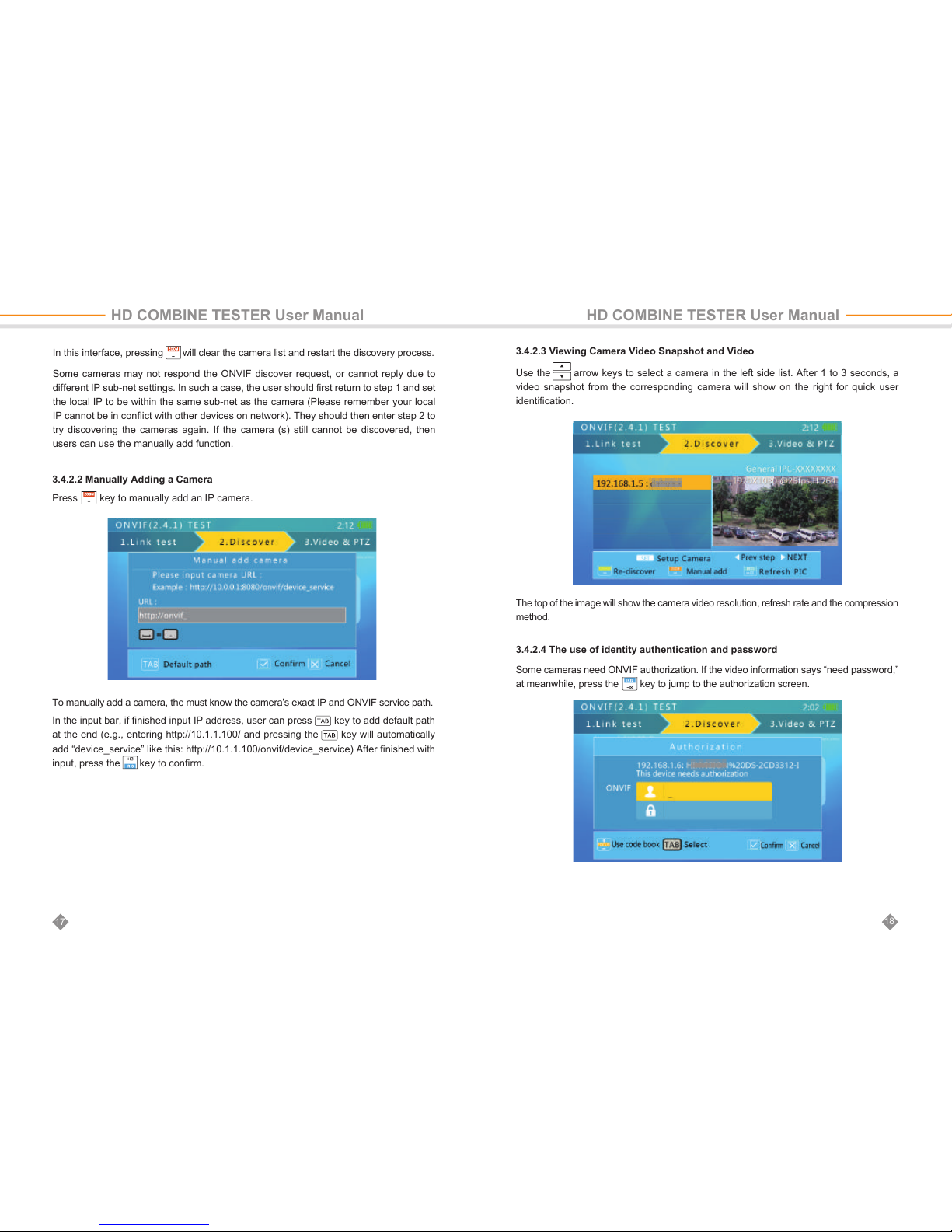
3.4.2.1 Discovering Cameras
When entering this step, the tester software will broadcast ONVIF discover data, trying
to discover ONVIF cameras. It will then add them to the list on the left.
The text above the list shows the number of discovered cameras.
When there are too many items on the list, then the triangle up/down prompt will show
on the left. This indicates that there are more items which are not shown.
Use the up/down arrow keys to select a camera in the list. The tester will automatically
initialize the link with the corresponding camera, then show the camera video snapshot
on the right side of screen.
HD COMBINE TESTER User Manual HD COMBINE TESTER User Manual
192.168.1.6: DAHUA
Page 11
In this interface, pressing will clear the camera list and restart the discovery process.
Some cameras may not respond the ONVIF discover request, or cannot reply due to
different IP sub-net settings. In such a case, the user should first return to step 1 and set
the local IP to be within the same sub-net as the camera (Please remember your local
IP cannot be in conflict with other devices on network). They should then enter step 2 to
try discovering the cameras again. If the camera (s) still cannot be discovered, then
users can use the manually add function.
18
17
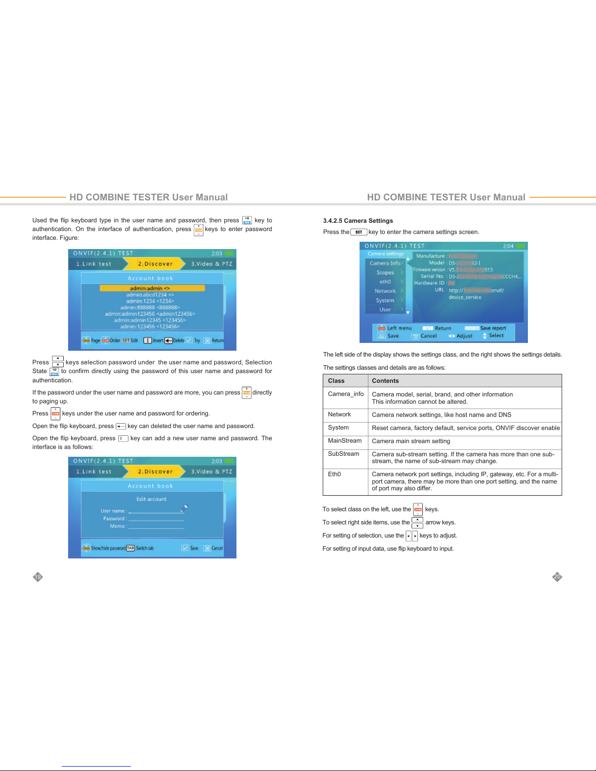
3.4.2.2 Manually Adding a Camera
Press key to manually add an IP camera.
To manually add a camera, the must know the camera’s exact IP and ONVIF service path.
In the input bar, if finished input IP address, user can press key to add default path
at the end (e.g., entering http://10.1.1.100/ and pressing the key will automatically
add “device_service” like this: http://10.1.1.100/onvif/device_service) After finished with
input, press the key to confirm.
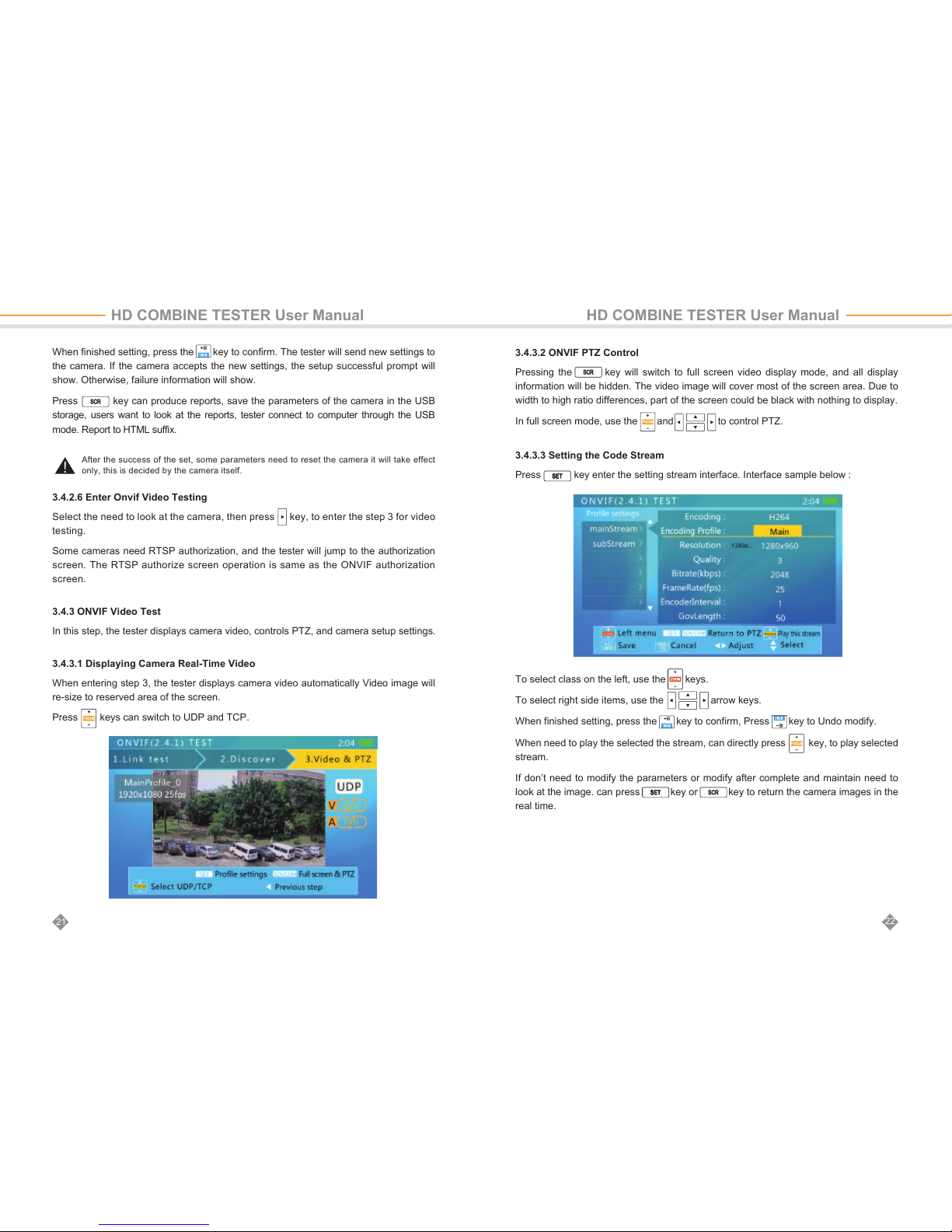
3.4.2.3 Viewing Camera Video Snapshot and Video
Use the arrow keys to select a camera in the left side list. After 1 to 3 seconds, a
video snapshot from the corresponding camera will show on the right for quick user
identification.
HD COMBINE TESTER User Manual HD COMBINE TESTER User Manual
The top of the image will show the camera video resolution, refresh rate and the compression
method.
3.4.2.4 The use of identity authentication and password
Some cameras need ONVIF authorization. If the video information says “need password,”
at meanwhile, press the key to jump to the authorization screen.
Page 12
20
19
3.4.2.5 Camera Settings
Press the key to enter the camera settings screen.
The left side of the display shows the settings class, and the right shows the settings details.
The settings classes and details are as follows:
To select class on the left, use the keys.
To select right side items, use the arrow keys.
For setting of selection, use the keys to adjust.
For setting of input data, use flip keyboard to input.
Used the flip keyboard type in the user name and password, then press key to
authentication. On the interface of authentication, press keys to enter password
interface. Figure:
Camera_info
Network
System
MainStream
SubStream
Eth0
Camera model, serial, brand, and other information
This information cannot be altered.
Camera network settings, like host name and DNS
Reset camera, factory default, service ports, ONVIF discover enable
Camera main stream setting
Camera sub-stream setting. If the camera has more than one sub-
stream, the name of sub-stream may change.
Camera network port settings, including IP, gateway, etc. For a multi-
port camera, there may be more than one port setting, and the name
of port may also differ.
Class Contents
HD COMBINE TESTER User Manual HD COMBINE TESTER User Manual
Press keys selection password under the user name and password, Selection
State to confirm directly using the password of this user name and password for
authentication.
If the password under the user name and password are more, you can press directly
to paging up.
Press keys under the user name and password for ordering.
Open the flip keyboard, press key can deleted the user name and password.
Open the flip keyboard, press key can add a new user name and password. The
interface is as follows:
Page 13
After the success of the set, some parameters need to reset the camera it will take effect
only, this is decided by the camera itself.
When finished setting, press the key to confirm. The tester will send new settings to
the camera. If the camera accepts the new settings, the setup successful prompt will
show. Otherwise, failure information will show.
Press key can produce reports, save the parameters of the camera in the USB
storage, users want to look at the reports, tester connect to computer through the USB
mode. Report to HTML suffix.
3.4.2.6 Enter Onvif Video Testing
Select the need to look at the camera, then press key, to enter the step 3 for video
testing.
Some cameras need RTSP authorization, and the tester will jump to the authorization
screen. The RTSP authorize screen operation is same as the ONVIF authorization
screen.
3.4.3 ONVIF Video Test
In this step, the tester displays camera video, controls PTZ, and camera setup settings.
3.4.3.1 Displaying Camera Real-Time Video
When entering step 3, the tester displays camera video automatically Video image will
re-size to reserved area of the screen.
Press keys can switch to UDP and TCP.
3.4.3.2 ONVIF PTZ Control
Pressing the key will switch to full screen video display mode, and all display
information will be hidden. The video image will cover most of the screen area. Due to
width to high ratio differences, part of the screen could be black with nothing to display.
In full screen mode, use the and to control PTZ.
3.4.3.3 Setting the Code Stream
Press key enter the setting stream interface. Interface sample below :
To select class on the left, use the keys.
To select right side items, use the arrow keys.
When finished setting, press the key to confirm, Press key to Undo modify.
When need to play the selected the stream, can directly press key, to play selected
stream.
If don’t need to modify the parameters or modify after complete and maintain need to
look at the image. can press key or key to return the camera images in the
real time.
22
21
HD COMBINE TESTER User Manual HD COMBINE TESTER User Manual
Page 14
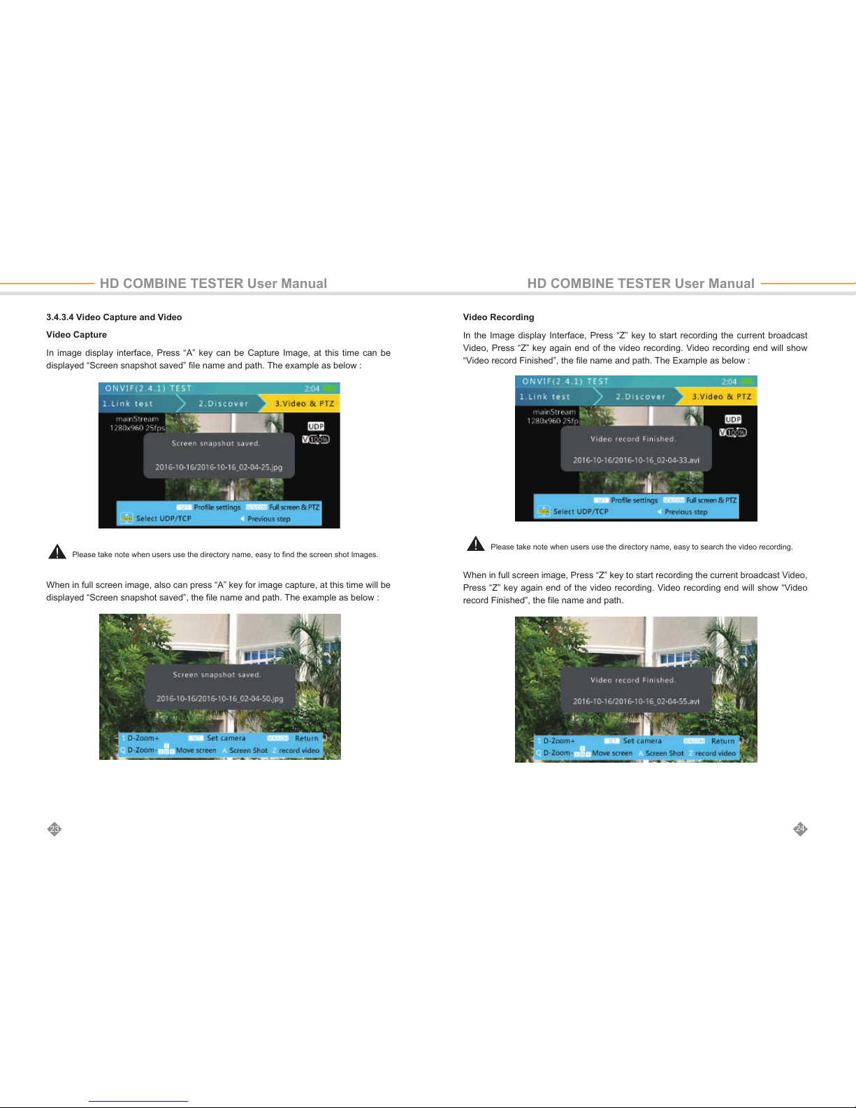
Please take note when users use the directory name, easy to find the screen shot Images.
Please take note when users use the directory name, easy to search the video recording.
3.4.3.4 Video Capture and Video
Video Capture
In image display interface, Press “A” key can be Capture Image, at this time can be
displayed “Screen snapshot saved” file name and path. The example as below :
When in full screen image, also can press “A” key for image capture, at this time will be
displayed “Screen snapshot saved”, the file name and path. The example as below :
Video Recording
In the Image display Interface, Press “Z” key to start recording the current broadcast
Video, Press “Z” key again end of the video recording. Video recording end will show
“Video record Finished”, the file name and path. The Example as below :
When in full screen image, Press “Z” key to start recording the current broadcast Video,
Press “Z” key again end of the video recording. Video recording end will show “Video
record Finished”, the file name and path.
24
23
HD COMBINE TESTER User Manual HD COMBINE TESTER User Manual
Page 15
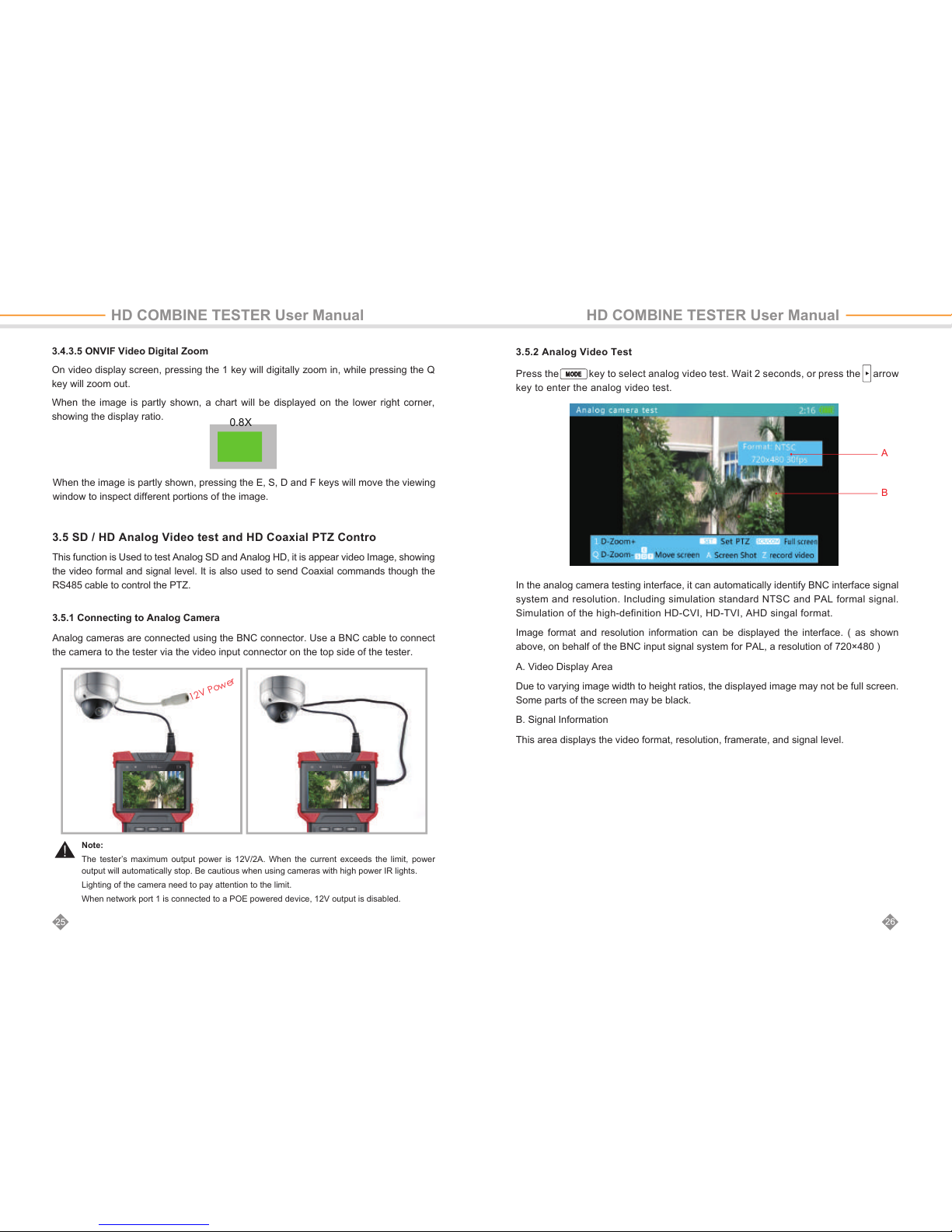
3.4.3.5 ONVIF Video Digital Zoom
On video display screen, pressing the 1 key will digitally zoom in, while pressing the Q
key will zoom out.
When the image is partly shown, a chart will be displayed on the lower right corner,
showing the display ratio.
When the image is partly shown, pressing the E, S, D and F keys will move the viewing
window to inspect different portions of the image.
0.8X
3.5.2 Analog Video Test
Press the key to select analog video test. Wait 2 seconds, or press the arrow
key to enter the analog video test.
In the analog camera testing interface, it can automatically identify BNC interface signal
system and resolution. Including simulation standard NTSC and PAL formal signal.
Simulation of the high-definition HD-CVI, HD-TVI, AHD singal format.
Image format and resolution information can be displayed the interface. ( as shown
above, on behalf of the BNC input signal system for PAL, a resolution of 720×480 )
A. Video Display Area
Due to varying image width to height ratios, the displayed image may not be full screen.
Some parts of the screen may be black.
B. Signal Information
This area displays the video format, resolution, framerate, and signal level.
A
B
HD COMBINE TESTER User Manual HD COMBINE TESTER User Manual
3.5 SD / HD Analog Video test and HD Coaxial PTZ Contro
This function is Used to test Analog SD and Analog HD, it is appear video Image, showing
the video formal and signal level. It is also used to send Coaxial commands though the
RS485 cable to control the PTZ.
3.5.1 Connecting to Analog Camera
Analog cameras are connected using the BNC connector. Use a BNC cable to connect
the camera to the tester via the video input connector on the top side of the tester.
Note:
The tester’s maximum output power is 12V/2A. When the current exceeds the limit, power
output will automatically stop. Be cautious when using cameras with high power IR lights.
Lighting of the camera need to pay attention to the limit.
When network port 1 is connected to a POE powered device, 12V output is disabled.
Page 16
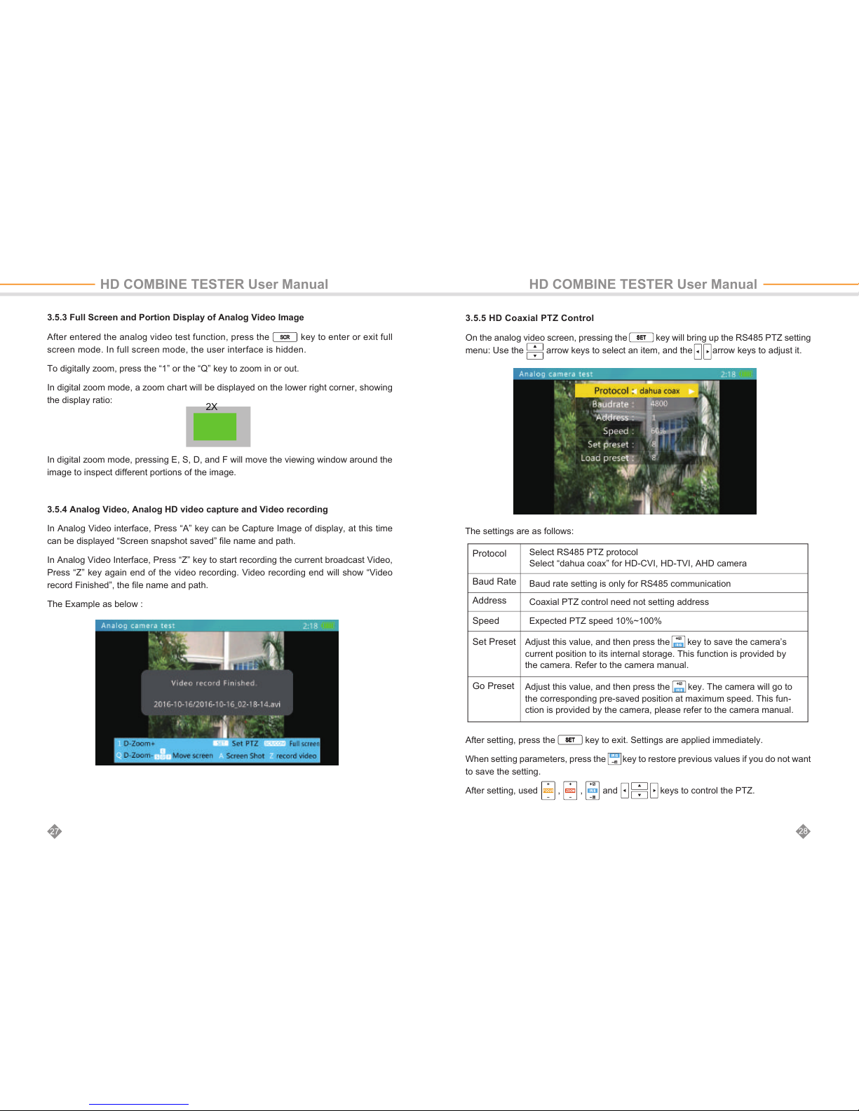
3.5.3 Full Screen and Portion Display of Analog Video Image
After entered the analog video test function, press the key to enter or exit full
screen mode. In full screen mode, the user interface is hidden.
To digitally zoom, press the “1” or the “Q” key to zoom in or out.
In digital zoom mode, a zoom chart will be displayed on the lower right corner, showing
the display ratio:
In digital zoom mode, pressing E, S, D, and F will move the viewing window around the
image to inspect different portions of the image.
3.5.4 Analog Video, Analog HD video capture and Video recording
In Analog Video interface, Press “A” key can be Capture Image of display, at this time
can be displayed “Screen snapshot saved” file name and path.
In Analog Video Interface, Press “Z” key to start recording the current broadcast Video,
Press “Z” key again end of the video recording. Video recording end will show “Video
record Finished”, the file name and path.
The Example as below :
2X
3.5.5 HD Coaxial PTZ Control
On the analog video screen, pressing the key will bring up the RS485 PTZ setting
menu: Use the arrow keys to select an item, and the arrow keys to adjust it.
After setting, press the key to exit. Settings are applied immediately.
When setting parameters, press the key to restore previous values if you do not want
to save the setting.
After setting, used , , and keys to control the PTZ.
The settings are as follows:
HD COMBINE TESTER User Manual HD COMBINE TESTER User Manual
Protocol
Baud Rate
Address
Speed
Set Preset
Go Preset
Adjust this value, and then press the key to save the camera’s
current position to its internal storage. This function is provided by
the camera. Refer to the camera manual.
Adjust this value, and then press the
key. The camera will go to
the corresponding pre-saved position at maximum speed. This fun-
ction is provided by the camera, please refer to the camera manual.
Select RS485 PTZ protocol
Select “dahua coax” for HD-CVI, HD-TVI, AHD camera
Baud rate setting is only for RS485 communication
Coaxial PTZ control need not setting address
Expected PTZ speed 10%~100%
Page 17
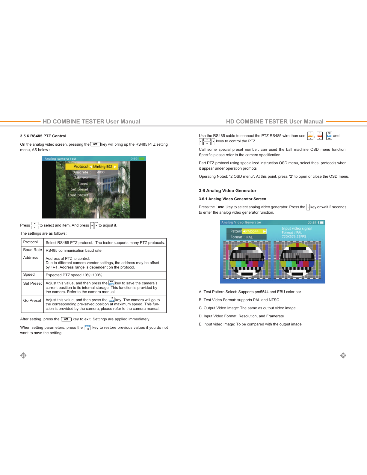
A. Test Pattern Select: Supports pm5544 and EBU color bar
B. Test Video Format: supports PAL and NTSC
C. Output Video Image: The same as output video image
D. Input Video Format, Resolution, and Framerate
E. Input video Image: To be compared with the output image
3.6 Analog Video Generator
3.6.1 Analog Video Generator Screen
Press the key to select analog video generator. Press the key or wait 2 seconds
to enter the analog video generator function.
HD COMBINE TESTER User Manual HD COMBINE TESTER User Manual
After setting, press the key to exit. Settings are applied immediately.
When setting parameters, press the key to restore previous values if you do not
want to save the setting.
Use the RS485 cable to connect the PTZ RS485 wire then use , , and
keys to control the PTZ.
Call some special preset number, can used the ball machine OSD menu function.
Specific please refer to the camera specification.
Part PTZ protocol using specialized instruction OSD menu, select thes protocols when
it appear under operation prompts
Operating Noted: “2 OSD menu”. At this point, press “2” to open or close the OSD menu.
3.5.6 RS485 PTZ Control
On the analog video screen, pressing the key will bring up the RS485 PTZ setting
menu, AS below :
Press to select and item. And press to adjust it.
The settings are as follows:
Protocol
Baud Rate
Address
Speed
Set Preset
Go Preset
Select RS485 PTZ protocol. The tester supports many PTZ protocols.
RS485 communication baud rate.
Address of PTZ to control.
Due to different camera vendor settings, the address may be offset
by +/-1. Address range is dependent on the protocol.
Expected PTZ speed 10%~100%
Adjust this value, and then press the key to save the camera’s
current position to its internal storage. This function is provided by
the camera. Refer to the camera manual.
Adjust this value, and then press the
key. The camera will go to
the corresponding pre-saved position at maximum speed. This fun-
ction is provided by the camera, please refer to the camera manual.
Page 18
999
9
9
9
199 1
3.7 RJ45 Cable TDR Test*
This function is used to test an RJ45 cable using a TDR ( Time Domain Reflection )
analysis method. Connection status and cable length can be measured.
Connected, open, and short statuses can be detected, and cable length is displayed.
The accuracy is within 1 meter. To measure a cable, only one end of the cable needs to
connect to tester, and the other end should be left open.
3.7.1 Cable TDR Test Screen and Operation
Press the key to select the cable TDR test function. Press the key, then to enter
the TDR test function:
Note:
Test result can be affected by temperature, moisture, cable diameter, and cable dielectric. Test
results are only for reference, not for formal measurement.
Contiguous measure is to help easily test multiple cables, and it will not increase test accuracy.
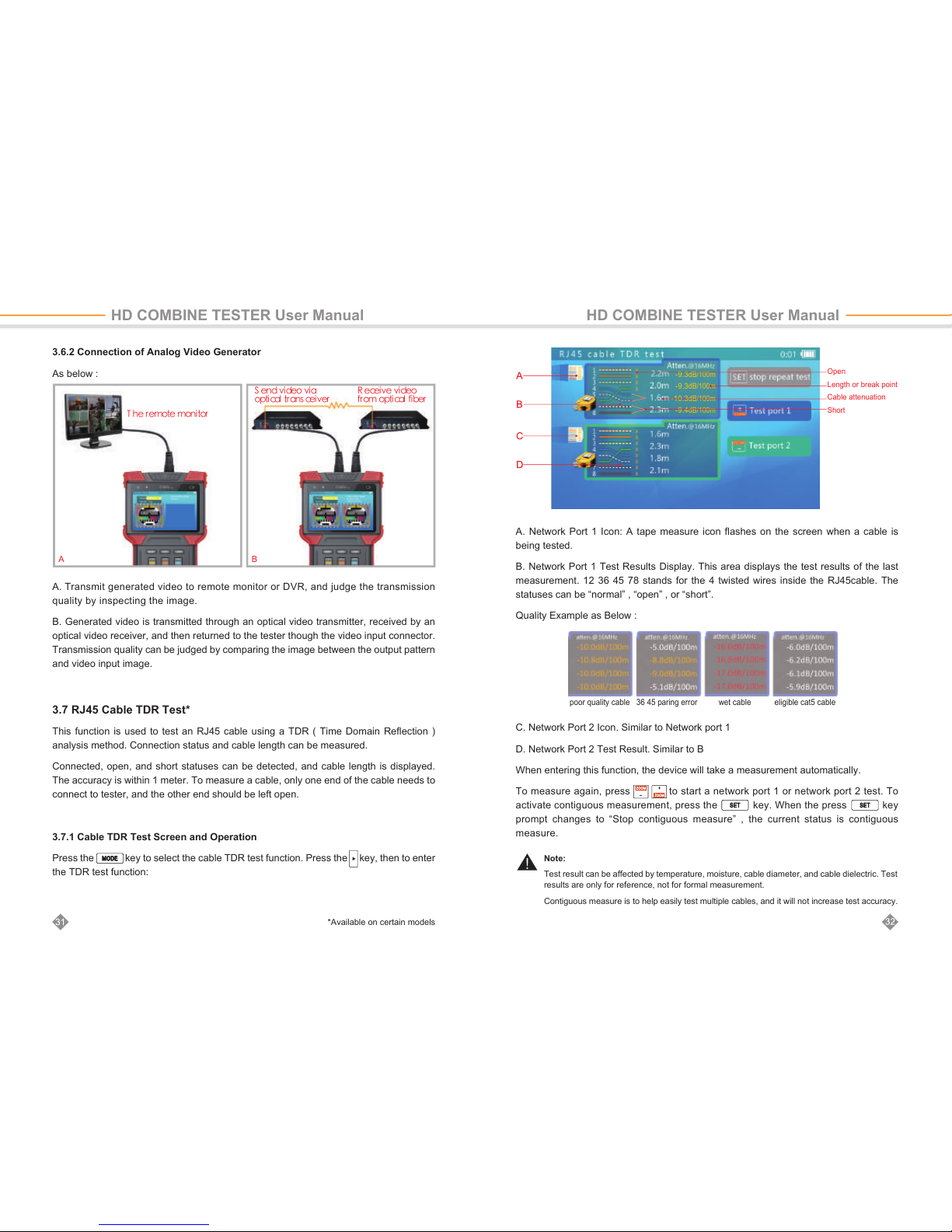
A. Transmit generated video to remote monitor or DVR, and judge the transmission
quality by inspecting the image.
B. Generated video is transmitted through an optical video transmitter, received by an
optical video receiver, and then returned to the tester though the video input connector.
Transmission quality can be judged by comparing the image between the output pattern
and video input image.
3.6.2 Connection of Analog Video Generator
As below :
HD COMBINE TESTER User Manual HD COMBINE TESTER User Manual
*Available on certain models
-9.3
dB/100m
-9.3
dB/100m
-10.3
dB/100m
-9.4
dB/100m
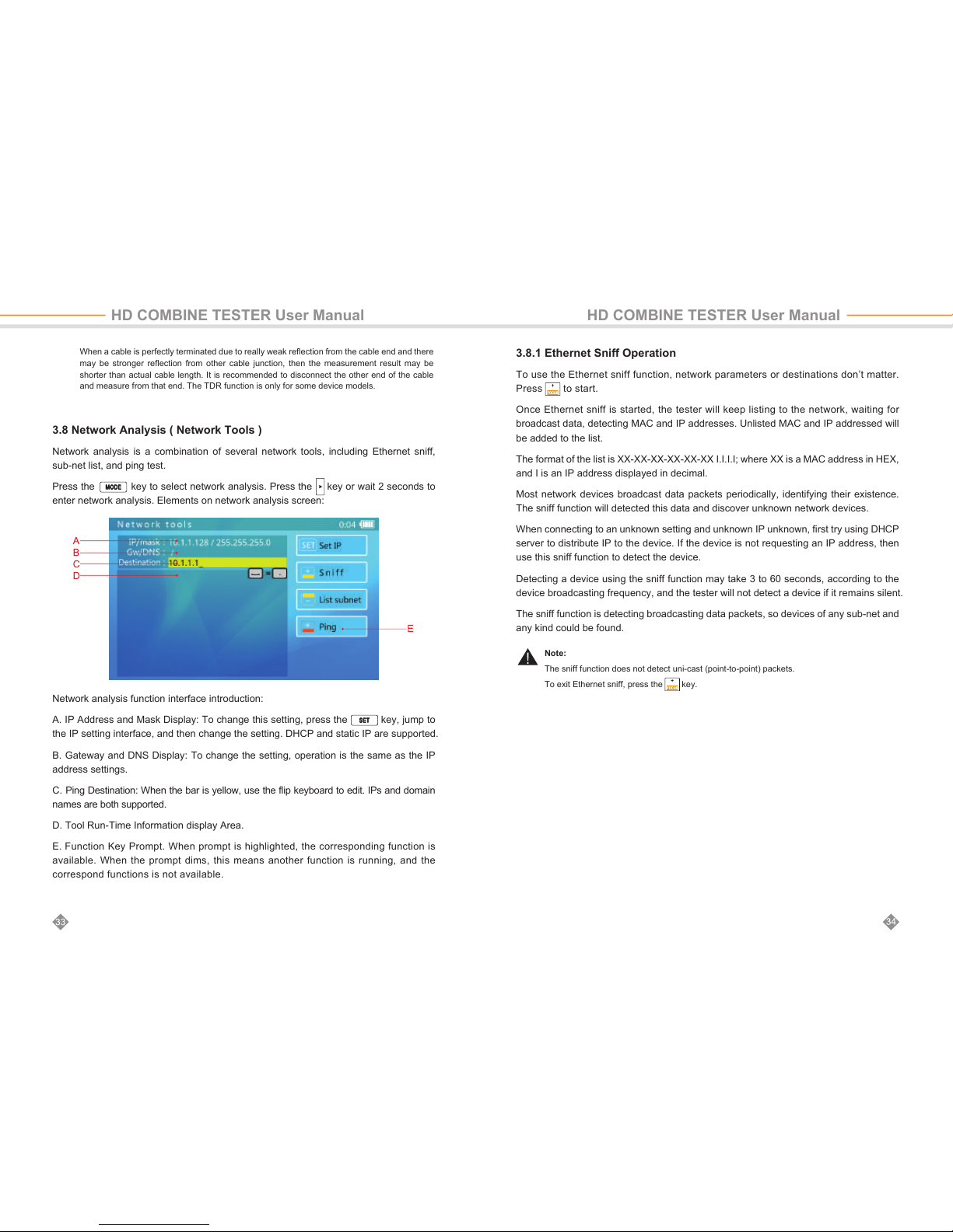
C. Network Port 2 Icon. Similar to Network port 1
D. Network Port 2 Test Result. Similar to B
When entering this function, the device will take a measurement automatically.
To measure again, press to start a network port 1 or network port 2 test. To
activate contiguous measurement, press the key. When the press key
prompt changes to “Stop contiguous measure” , the current status is contiguous
measure.
A. Network Port 1 Icon: A tape measure icon flashes on the screen when a cable is
being tested.
B. Network Port 1 Test Results Display. This area displays the test results of the last
measurement. 12 36 45 78 stands for the 4 twisted wires inside the RJ45cable. The
statuses can be “normal” , “open” , or “short”.
Quality Example as Below :
poor quality cable 36 45 paring error wet cable eligible cat5 cable
Open
Length or break point
Cable attenuation
Short
A B
Page 19
3.8 Network Analysis ( Network Tools )
Network analysis is a combination of several network tools, including Ethernet sniff,
sub-net list, and ping test.
Press the key to select network analysis. Press the key or wait 2 seconds to
enter network analysis. Elements on network analysis screen:
3.8.1 Ethernet Sniff Operation
To use the Ethernet sniff function, network parameters or destinations don’t matter.
Press to start.
Once Ethernet sniff is started, the tester will keep listing to the network, waiting for
broadcast data, detecting MAC and IP addresses. Unlisted MAC and IP addressed will
be added to the list.
The format of the list is XX-XX-XX-XX-XX-XX I.I.I.I; where XX is a MAC address in HEX,
and I is an IP address displayed in decimal.
Most network devices broadcast data packets periodically, identifying their existence.
The sniff function will detected this data and discover unknown network devices.
When connecting to an unknown setting and unknown IP unknown, first try using DHCP
server to distribute IP to the device. If the device is not requesting an IP address, then
use this sniff function to detect the device.
Detecting a device using the sniff function may take 3 to 60 seconds, according to the
device broadcasting frequency, and the tester will not detect a device if it remains silent.
The sniff function is detecting broadcasting data packets, so devices of any sub-net and
any kind could be found.
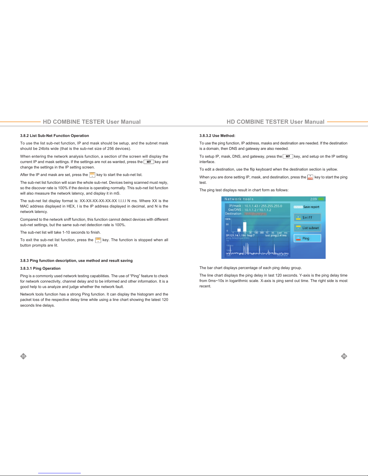
Network analysis function interface introduction:
A. IP Address and Mask Display: To change this setting, press the key, jump to
the IP setting interface, and then change the setting. DHCP and static IP are supported.
B. Gateway and DNS Display: To change the setting, operation is the same as the IP
address settings.
C. Ping Destination: When the bar is yellow, use the flip keyboard to edit. IPs and domain
names are both supported.
D. Tool Run-Time Information display Area.
E. Function Key Prompt. When prompt is highlighted, the corresponding function is
available. When the prompt dims, this means another function is running, and the
correspond functions is not available.
When a cable is perfectly terminated due to really weak reflection from the cable end and there
may be stronger reflection from other cable junction, then the measurement result may be
shorter than actual cable length. It is recommended to disconnect the other end of the cable
and measure from that end. The TDR function is only for some device models.
Note:
The sniff function does not detect uni-cast (point-to-point) packets.
To exit Ethernet sniff, press the key.
HD COMBINE TESTER User Manual HD COMBINE TESTER User Manual
Page 20
3.8.2 List Sub-Net Function Operation
To use the list sub-net function, IP and mask should be setup, and the subnet mask
should be 24bits wide (that is the sub-net size of 256 devices).
When entering the network analysis function, a section of the screen will display the
current IP and mask settings. If the settings are not as wanted, press the key and
change the settings in the IP setting screen.
After the IP and mask are set, press the key to start the sub-net list.
The sub-net list function will scan the whole sub-net. Devices being scanned must reply,
so the discover rate is 100% if the device is operating normally. This sub-net list function
will also measure the network latency, and display it in mS.
The sub-net list display format is: XX-XX-XX-XX-XX-XX I.I.I.I N ms. Where XX is the
MAC address displayed in HEX, I is the IP address displayed in decimal, and N is the
network latency.
Compared to the network sniff function, this function cannot detect devices with different
sub-net settings, but the same sub-net detection rate is 100%.
The sub-net list will take 1-10 seconds to finish.
To exit the sub-net list function, press the key. The function is stopped when all
button prompts are lit.
3.8.3 Ping function description, use method and result saving
3.8.3.1 Ping Operation
Ping is a commonly used network testing capabilities. The use of “Ping” feature to check
for network connectivity, channel delay and to be informed and other information. It is a
good help to us analyze and judge whether the network fault.
Network tools function has a strong Ping function. It can display the histogram and the
packet loss of the respective delay time while using a line chart showing the latest 120
seconds line delays.
HD COMBINE TESTER User Manual HD COMBINE TESTER User Manual
3.8.3.2 Use Method:
To use the ping function, IP address, masks and destination are needed. If the destination
is a domain, then DNS and gateway are also needed.
To setup IP, mask, DNS, and gateway, press the key, and setup on the IP setting
interface.
To edit a destination, use the flip keyboard when the destination section is yellow.
When you are done setting IP, mask, and destination, press the key to start the ping
test.
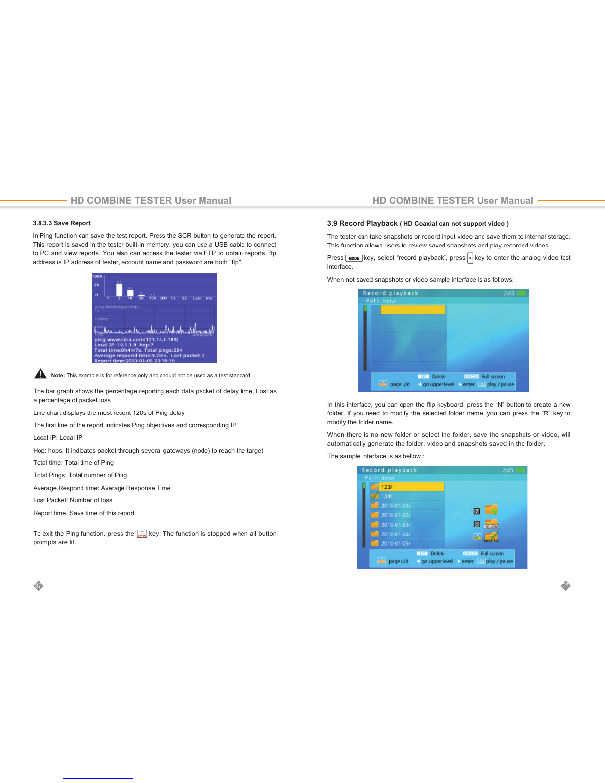
The ping test displays result in chart form as follows:
The bar chart displays percentage of each ping delay group.
The line chart displays the ping delay in last 120 seconds. Y-axis is the ping delay time
from 0ms~10s in logarithmic scale. X-axis is ping send out time. The right side is most
recent.
Page 21
38
37
HD COMBINE TESTER User Manual HD COMBINE TESTER User Manual
3.8.3.3 Save Report
In Ping function can save the test report. Press the SCR button to generate the report.
This report is saved in the tester built-in memory, you can use a USB cable to connect
to PC and view reports. You also can access the tester via FTP to obtain reports. ftp
address is IP address of tester, account name and password are both "ftp".
3.9 Record Playback ( HD Coaxial can not support video )
The tester can take snapshots or record input video and save them to internal storage.
This function allows users to review saved snapshots and play recorded videos.
Press key, select “record playback”, press key to enter the analog video test
interface.
When not saved snapshots or video sample interface is as follows:
In this interface, you can open the flip keyboard, press the “N” button to create a new
folder, if you need to modify the selected folder name, you can press the “R” key to
modify the folder name.
When there is no new folder or select the folder, save the snapshots or video, will
automatically generate the folder, video and snapshots saved in the folder.
The sample interface is as bellow :
The bar graph shows the percentage reporting each data packet of delay time, Lost as
a percentage of packet loss
Line chart displays the most recent 120s of Ping delay
The first line of the report indicates Ping objectives and corresponding IP
Local IP: Local IP
Hop: hops. It indicates packet through several gateways (node) to reach the target
Total time: Total time of Ping
Total Pings: Total number of Ping
Average Respond time: Average Response Time
Lost Packet: Number of loss
Report time: Save time of this report
To exit the Ping function, press the key. The function is stopped when all button
prompts are lit.
Note: This example is for reference only and should not be used as a test standard.
Page 22
In the partial magnification mode, you can press the “E” “S” “D” “F” keys to move the
display area to view different parts of the image.
Press the button to delete the snapshots, press the key to confirm the deletion,
press the other keys to cancel.
Press to exit the full screen shot display
In the Full-screen video playback interface
In this interface, press the keys to play back the video files, press the key and the
key to play single frame, press the key to pause / play. Press to fast forward
/ rewind.
Open the flip keyboard, press the “1” “Q” buttons to zoom in or out the recorded image.
To achieve a partial magnified display.
To operating with videos and snapshots:
When you press the keys to select a snapshot or video file, the right side will auto-
matically play snapshot or video.
When more files, press the keys can be turned to view the folder.
Press key to delete the folder, press key to delete, press other keys to cancel.
When the selected file is the video, press the button on the right side to play the video
playback and pause operation
Press to return to the previous directory
Press or the key to enter the full screen display.
In this interface, you can operate the folder:
Press keys to view the folder up and down.
When more files, press the keys can be turned to view the folder.
Press to delete the folder, press to delete, press other keys to cancel.
When you select a folder, press the key, you can check this folder, the snapshot and
video files are saved in this folder.
Press to enter the folder the next level of directory, in this directory can save the video
and snapshot to operate.
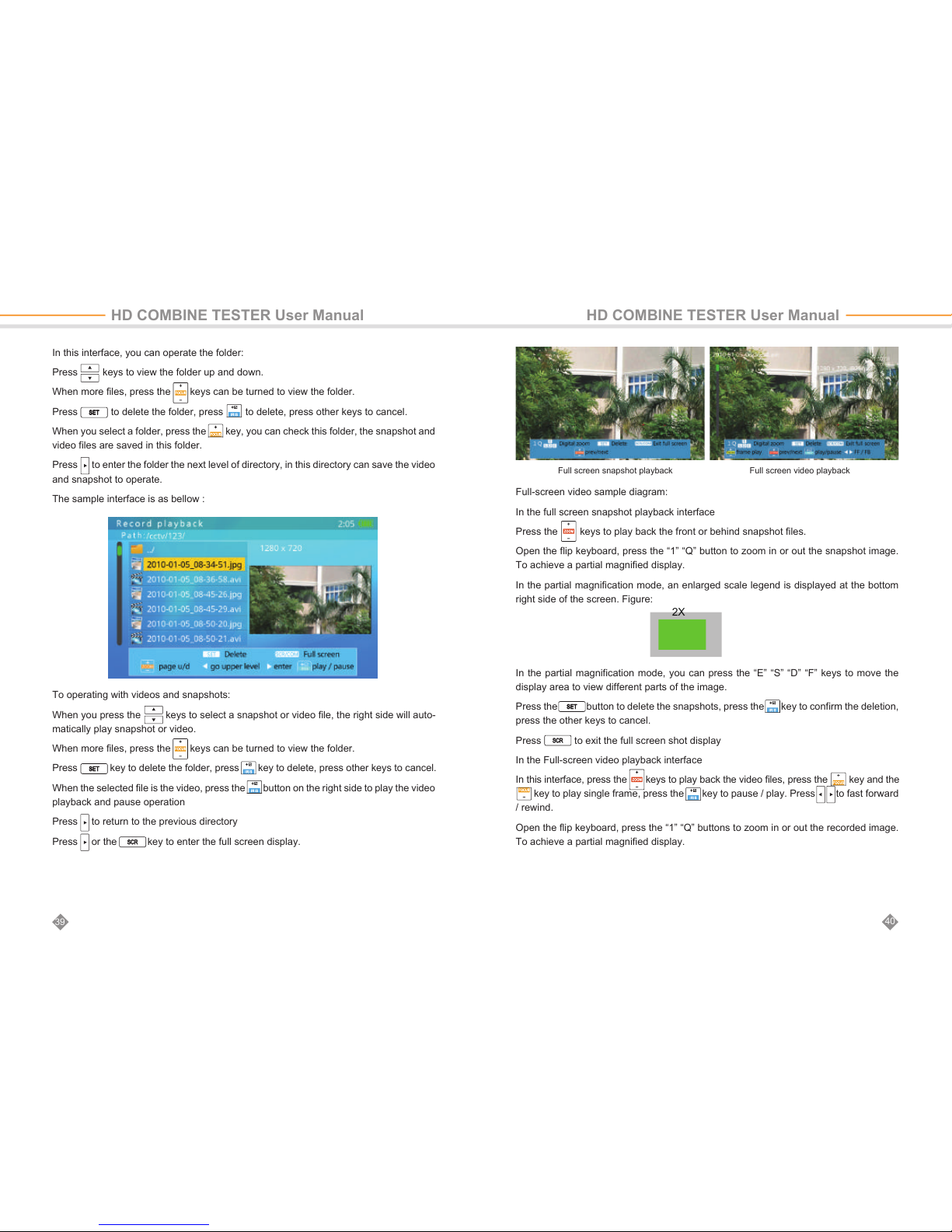
The sample interface is as bellow :
40
39
2X
HD COMBINE TESTER User Manual HD COMBINE TESTER User Manual
Full-screen video sample diagram:
In the full screen snapshot playback interface
Press the keys to play back the front or behind snapshot files.
Open the flip keyboard, press the “1” “Q” button to zoom in or out the snapshot image.
To achieve a partial magnified display.
In the partial magnification mode, an enlarged scale legend is displayed at the bottom
right side of the screen. Figure:
Full screen snapshot playback Full screen video playback
Page 23
42
41
HD COMBINE TESTER User Manual HD COMBINE TESTER User Manual
*Available on certain models
In the partial magnification mode, you can press the “E” “S” “D” “F” keys to move the
display area to view different parts of the image.
Press the button to delete the recording, press the key to confirm the deletion,
press the other keys to cancel.
Press to exit full screen video playback.
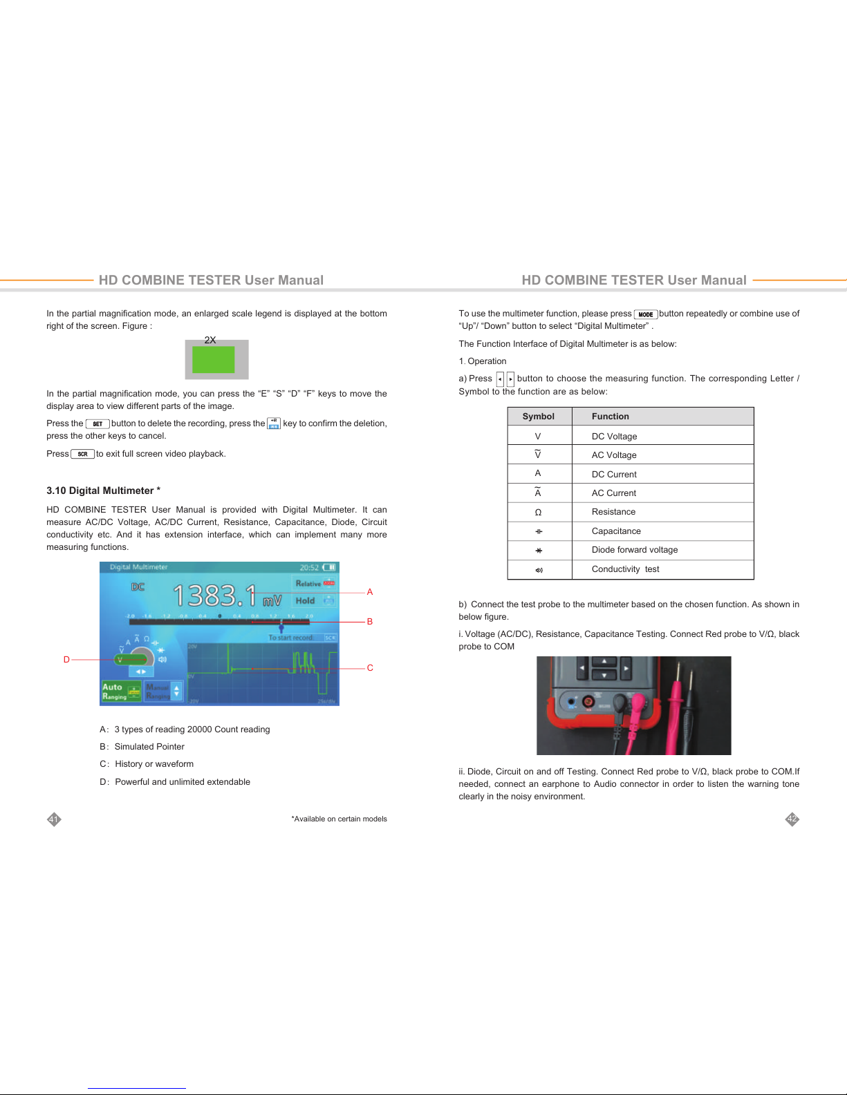
In the partial magnification mode, an enlarged scale legend is displayed at the bottom
right of the screen. Figure :
3.10 Digital Multimeter *
HD COMBINE TESTER User Manual is provided with Digital Multimeter. It can
measure AC/DC Voltage, AC/DC Current, Resistance, Capacitance, Diode, Circuit
conductivity etc. And it has extension interface, which can implement many more
measuring functions.
To use the multimeter function, please press button repeatedly or combine use of
“Up”/ “Down” button to select “Digital Multimeter” .
The Function Interface of Digital Multimeter is as below:
1. Operation
a) Press button to choose the measuring function. The corresponding Letter /
Symbol to the function are as below:
b) Connect the test probe to the multimeter based on the chosen function. As shown in
below figure.
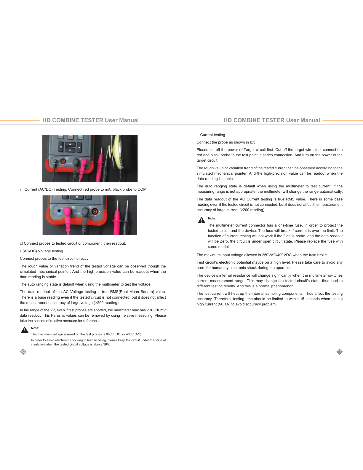
i. Voltage (AC/DC), Resistance, Capacitance Testing. Connect Red probe to V/Ω, black
probe to COM
ii. Diode, Circuit on and off Testing. Connect Red probe to V/Ω, black probe to COM.If
needed, connect an earphone to Audio connector in order to listen the warning tone
clearly in the noisy environment.
2X
A
B
C
D
A:3 types of reading 20000 Count reading
B:Simulated Pointer
C:History or waveform
D:Powerful and unlimited extendable
DC Voltage
AC Voltage
DC Current
AC Current
Resistance
Capacitance
Diode forward voltage
Conductivity test
Symbol Function
V
V
A
A
Ω
~
~
Page 24
Note:
The maximum voltage allowed on the test probes is 600V (DC) or 400V (AC).
In order to avoid electronic shocking to human being, please keep the circuit under the state of
insulation when the tested circuit voltage is above 36V.
Note:
The multimeter current connector has a one-time fuse. In order to protect the
tested circuit and the device. The fuse will break if current is over the limit. The
function of current testing will not work if the fuse is broke, and the data readout
will be Zero, the circuit is under open circuit state. Please replace the fuse with
same model.
44
43
iii. Current (AC/DC) Testing. Connect red probe to mA, black probe to COM.
c) Connect probes to tested circuit or component, then readout.
i. (AC/DC) Voltage testing
Connect probes to the test circuit directly.
The rough value or variation trend of the tested voltage can be observed though the
simulated mechanical pointer. And the high-precision value can be readout when the
data reading is stable.
The auto ranging state is default when using the multimeter to test the voltage.
The data readout of the AC Voltage testing is true RMS(Root Mean Square) value.
There is a base reading even if the tested circuit is not connected, but it does not affect
the measurement accuracy of large voltage (>200 reading) .
In the range of the 2V, even if test probes are shorted, the multimeter may has -10~+10mV
data readout. This Parasitic values can be removed by using relative measuring. Please
take the section of relative measure for reference.
HD COMBINE TESTER User Manual HD COMBINE TESTER User Manual
ii. Current testing
Connect the probe as shown in b.3
Please cut off the power of Target circuit first. Cut off the target wire also, connect the
red and black probe to the test point in series connection. And turn on the power of the
target circuit.
The rough value or variation trend of the tested current can be observed according to the
simulated mechanical pointer. And the high-precision value can be readout when the
data reading is stable.
The auto ranging state is default when using the multimeter to test current. If the
measuring range is not appropriate, the multimeter will change the range automatically.
The data readout of the AC Current testing is true RMS value. There is some base
reading even if the tested circuit is not connected, but it does not affect the measurement
accuracy of large current (>200 reading) .
The maximum input voltage allowed is 250VAC/400VDC when the fuse broke.
Test circuit’s electronic potential maybe on a high level. Please take care to avoid any
harm for human by electronic shock during the operation.
The device’s internal resistance will change significantly when the multimeter switches
current measurement range. This may change the tested circuit’s state, thus lead to
different testing results. And this is a normal phenomenon.
The test current will heat up the internal sampling components. Thus affect the testing
accuracy. Therefore, testing time should be limited to within 15 seconds when testing
high current (>0.1A),to avoid accuracy problem.
Page 25
Note:
Please confirm the tested circuit is powered-off, otherwise, the exact results can’t be
measured.
The meter will use different current to measure resistors in different range. If the target resistor
or circuit is not pure resistive load, the reading may not be the same in different measurement
range. And this is a normal phenomenon.
Note:
The diode should be tested alone, not be installed in the circuit.
Note:
The capacitor should be tested by alone, instead of installed in a circuit. Otherwise, it may get
a wrong testing result or cannot get the data readout.
The testing result may became larger due to capacitor leakage. And if the capacitor leaks
badly, it may not get the data readout.
If the capacitor has a higher charged voltage (>5V) when testing, it may not be tested normally.
If the voltage in the capacitor is over the maximum of the internal protection circuit, it may
damage the meter.
If the capacitor has high charged voltage (>36V), it may do harm to human when touching.
46
45
iii. Resistance Testing
This function can test resistor or circuit’s resistance value.
Connect the probes to the resistor or two ends of the test circuit, the multimeter will
auto-adjust to a suitable range and do testing.
The rough value or variation trend of the tested resistance can be observede
according to the simulated mechanical pointer. And the high-precision value can be
readout when the data reading is stable.
When testing the low resistance, please connect the probe in short circuit first, and
enter to relative test mode. This operation can remove the test probe resistance.
Please read the section of relative measure for reference.
v. Testing Diode
The function of diode testing can measure diode’s forward voltage drop, and help to
find diode’s positive and negative terminals.
Connect red probe to diode’s positive electrode (Terminal A ), black probe to
diode’s negative electrode (Terminal K). The tested diode’s forward voltage drop
will be displayed by the device.
If tested value is ‘OL’, that means the connection of diode polarity is wrong, or the
diode is damaged.
The meter’s buzzer will sound when the tested diode’s forward voltage is lower than
30mV. It means the tested diode may be breakdown and damaged.
Earphones can be used in the noisy environment.
vi. Test Circuit Conductivity
The functions of Circuit Conductivity testing is to test the resistance of the circuit,
whereby to judge the circuit is conductive or open circuit.
Please cut off the circuit’s power, and wait for the possibly existed electricity in
capacitors of the target circuit to be totally discharged.
Connect the red and black probe to the tested circuit.When the resistance value of
the tested circuit will be displayed.The meter’s buzzer will sound when the tested
circuit’s resistance is lower than 30Ω, that means the circuit conductive.
iv. Testing Capacitance
Please discharge the Capacitor before testing. Especially for large capacitor
(>100uF) or high voltage capacitor (withstand voltage>50V). Please reconfirm to
discharge the capacitor in case of any harm to human or damage to the meter.
For small capacitor(<100uf), and the charged voltage lower than 5V, the meter will
automatically discharge the capacitor before testing.
Please connect the red and black probe to the tested capacitor’s pins. Please
connect the red probe to positive electrode, and black probe to negative electrode
if the capacitor has polarity.
The multimeter will automatically select a suitable range for testing. The rough
value or variation trend of the tested capacitance can be observed according to the
simulated mechanical pointer. And the high-precision value can be readout when
the data reading is stable.
The testing time may be long (>1s) if the tested tested capacitance is
large(>1000uF). This is a normal phenomenon.
HD COMBINE TESTER User Manual HD COMBINE TESTER User Manual
Page 26
Note:
The circuit conductive or open is a relative concept. User should judge according to particular
circuit and measured value, instead of judge it base on the buzzer.
The measuring value may vary continuously when the tested circuit have large capacitance,
because the tested circuit’s capacitance is being recharged. It’s a normal phenomenon.During
recharging, the smaller resistance can be considered as the circuit is connected, while it should
be judged till the data readout is on stable.
The tested circuit should be powered off, otherwise, it can not get the correct testing result.
Note:
The meter is still on measuring under locked state. Auto measuring range, beep tone and data
recording function are still working also. The chart is still on refreshing under data history chart
display. The wave is frozen under the mode of waveform display.
48
47
d) Auto / Manual Measuring Range
It shows that the device is on Auto Range state when the auto measuring range
indicator is on green light.User can press up/ down arrow key to enter manual
measuring range when testing voltage, current, resistance and capacitance. At this
time, the indicator of manual measuring range is on green light and auto measuring
range is on transparent state. Press up / down arrow button will adjust the
measuring range.
Press FOCUS+ button to turn back to auto ranging.
e) HOLD Function
Press ZOOM- button to lock the data readout when testing. HOLD is indicated as
green. Press ZOOM- button again to unlock the data readout.
f) Relative Testing
Press ZOOM+ button to enter the mode of Relative Measuring when testing. The
indicator of relative measuring turn green. And the meter will switch to manual
ranging mode at the same time. The device will record the current reading as
reference value once press down the button. And to subtract the new measuring
result with the reference value, as well to show the difference.
Press ZOOM+ button again to exit difference testing, the indicator of difference
measuring turn transparent.
To test small voltage (2V range) or small resistance (2kΩrange), user can user
relative measuring function to reduce the influence of stray voltage and test probe
resistance. Operation procedure: connect the probes in short circuit first, and enter
the mode of relative testing when the data readout is stable. And then measure the
tested circuit or resistor.
g) Data Recording Function
The device has data recording function.Press SCR button to start recording. The
recording time will be displayed on data recording time frame.
Press SCR button again to stop the data recording.
When recording, if the meter is under auto ranging, the range change information is
also recorded in file.
Please adjust the auto power off option to suitable time or turn off this option if long
time data recording is needed.
The data recording is saved in the internal memory of the tester. The file name is
the date and time of when the recording started. For example:
/cctv/DMM/2016-10-10_12-01-01.txt. The first line of the file is measuring setup,
including measuring item, range, unit, start time, interval time etc. From the second
line ,each line is a recorded data, without unit.
h) Precautions
i. Avoid electrical shock when testing high voltage circuit. Please don’t touch any
metal parts of the probe, otherwise it may do harm to human by shocking.
ii. The electronic measurement part of the multimeter are electrically insulated from
other circuits. It’s safe to touch non-electric-measurement parts when the probe is
connecting to target circuit with voltage below 600V. The non-electric-measurement
parts are: BNC Connector, Network Port, Audio input connector, earphone
connector, recharging connector, battery port, RS485 connector, USB connector
and power output port.
iii. The electronic measurement connectors are COM, V/Ω、 mA connector. Please
don’t touch metal parts of these connectors when testing high voltage circuit
(>36V).
iv. Improperly connect the voltage may damage the meter or tested circuit when
testing resistance, capacitance, diode and conductivity. The meter has automatic
protection capability if it improperly connect to a certain range of unwanted voltage.
However, this protection can only be use by limitation. It will lower the meter’s
accuracy if protection too many times. The device will be damaged permanently if
connect to the voltage which is beyond the protection capability.
v. The earphone connector can connect to 3.5mm 3-pin earphone, and it also can
connect with some 4-pin earphone.
vi. The earphone connector is also a expansion port. It can connect to dedicated
extension accessories.
HD COMBINE TESTER User Manual HD COMBINE TESTER User Manual
Page 27
Note:
DC 2V,DC 20mA
For the range of DC 2V and DC 20mA, no load reading should be subtracted.
When measuring small resistors, resistance of the probes should be subtracted.
50
49
HD COMBINE TESTER User Manual HD COMBINE TESTER User Manual
Item Range
Reading
Range
Minimum
Resolution
Accuracy
DCV
ACV
True RMS
DC Current
AC Current
True RMS
Resistor
Capacitance
Diode forward voltage
Conducvity
2V,20V,200V,600V
20V,200V,600V
20mA,200mA,2000mA
20mA,200mA,2000mA
2KΩ,20KΩ,200KΩ,
2MΩ,20MΩ
2nF,20nF,200nF,2uF,
20uF,200uF,2mF,20mF
2V
2KΩ
±19999
±1999
±19999
±1999
0~19999
0~1999
0~19999
0~19999
0.1mV
1V
1uA
1uA
0.1Ω
1pF
0.1mV
0.1Ω
±0.1%+8*
±1.2%+3
±0.1%+8*
±1.2%+3
±0.1%+8*
±4%+5
±0.1%+20
±0.1%+20
i) Technical Data-sheet / Parameter Table
Measuring Range and Accuracy
Electronic Parameters
Item Parameters Description
Measurement features
Factory calibraon
temperature
Temperature stability
User self calibraon range
25±5℃
<100ppm/℃
±1%
Except for large current
measurement
Data rate
Analog meter refresh rate
Data history chart X axis
Waveform display mode
X axis
Waveform refresh rate
Ac measurement
frequency range
Diode current
measurement
Breakdown prompt
threshold
Conducvity test current
Conducvity beeper
threshold
Conducvity beeper
response me
Current measurement
resistance
Data recording frequency
Data record length
Safety parameters
Resistance, Capacitance,
Diode Measurement
Protecon
Fuse
Electrical insulaon
5 reading/s
2 reading/s
0.1~5 reading/s
20~40fps
1s/div,5s/div,25s/div
10ms/div
1me/s
0Hz~1000Hz
1mA±5%
30mV
1mA±5%
30Ω
<2mS
20mA Grade:5Ω±5%
200mA Grade:1Ω±10%
2000mA Grade:0.1Ω~0.2Ω
2 records/second
0.5s~9999h
<400V
Size:5*20mm,2A/250V
>1.5KV
AC Voltage, AC Current tesng
Capacitance Tesng
Except for Capacitance Tesng
Automac adapt
No synchronizaon
Not Including probe’s resistance.
Only for current measurement
mA,COM,V/Ω are electronic
measurement connectors,
which are insulated from all
other interfaces.
Harmonics above 1KHz will
induce error.
DC Voltage, DC Current,
Resistance measurement,
Diode tesng, Conducvity
Connect to the voltage beyond
the range will cause the meter
to be damaged permanently .
Page 28
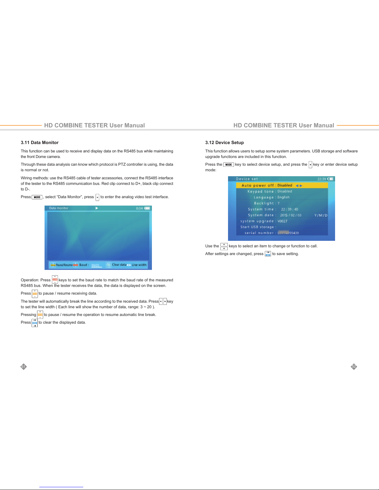
Operation: Press keys to set the baud rate to match the baud rate of the measured
RS485 bus. When the tester receives the data, the data is displayed on the screen.
Press to pause / resume receiving data.
The tester will automatically break the line according to the received data. Press key
to set the line width ( Each line will show the number of data, range: 3 ~ 20 ).
Pressing to pause / resume the operation to resume automatic line break.
Press to clear the displayed data.
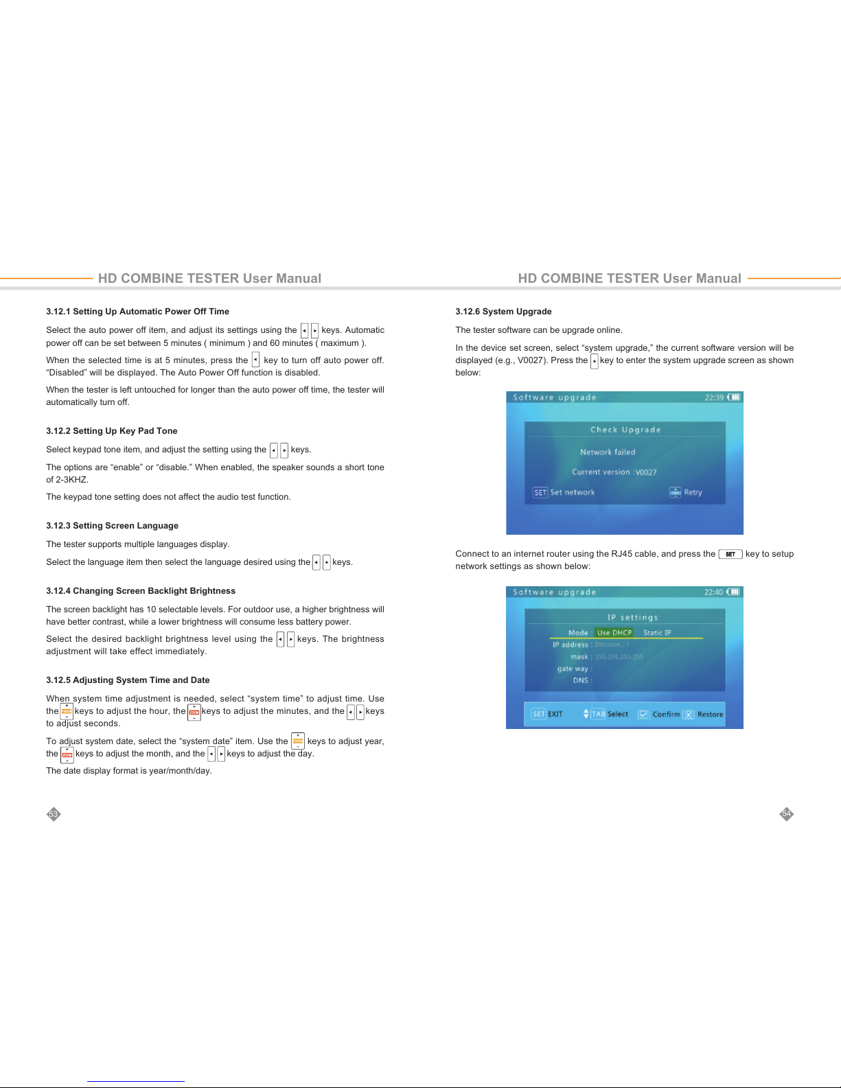
3.12 Device Setup
This function allows users to setup some system parameters. USB storage and software
upgrade functions are included in this function.
Press the key to select device setup, and press the key or enter device setup
mode:
Use the keys to select an item to change or function to call.
After settings are changed, press to save setting.
3.11 Data Monitor
This function can be used to receive and display data on the RS485 bus while maintaining
the front Dome camera.
Through these data analysis can know which protocol is PTZ controller is using, the data
is normal or not.
Wiring methods: use the RS485 cable of tester accessories, connect the RS485 interface
of the tester to the RS485 communication bus. Red clip connect to D+, black clip connect
to D-.
Press , select “Data Monitor”, press to enter the analog video test interface.
52
51
HD COMBINE TESTER User Manual HD COMBINE TESTER User Manual
Page 29
3.12.1 Setting Up Automatic Power Off Time
Select the auto power off item, and adjust its settings using the keys. Automatic
power off can be set between 5 minutes ( minimum ) and 60 minutes ( maximum ).
When the selected time is at 5 minutes, press the key to turn off auto power off.
“Disabled” will be displayed. The Auto Power Off function is disabled.
When the tester is left untouched for longer than the auto power off time, the tester will
automatically turn off.
3.12.2 Setting Up Key Pad Tone
Select keypad tone item, and adjust the setting using the keys.
The options are “enable” or “disable.” When enabled, the speaker sounds a short tone
of 2-3KHZ.
The keypad tone setting does not affect the audio test function.
3.12.3 Setting Screen Language
The tester supports multiple languages display.
Select the language item then select the language desired using the keys.
3.12.4 Changing Screen Backlight Brightness
The screen backlight has 10 selectable levels. For outdoor use, a higher brightness will
have better contrast, while a lower brightness will consume less battery power.
Select the desired backlight brightness level using the keys. The brightness
adjustment will take effect immediately.
3.12.5 Adjusting System Time and Date
When system time adjustment is needed, select “system time” to adjust time. Use
the keys to adjust the hour, the keys to adjust the minutes, and the keys
to adjust seconds.
To adjust system date, select the “system date” item. Use the keys to adjust year,
the keys to adjust the month, and the keys to adjust the day.
The date display format is year/month/day.
HD COMBINE TESTER User Manual HD COMBINE TESTER User Manual
3.12.6 System Upgrade
The tester software can be upgrade online.
In the device set screen, select “system upgrade,” the current software version will be
displayed (e.g., V0027). Press the key to enter the system upgrade screen as shown
below:
Connect to an internet router using the RJ45 cable, and press the key to setup
network settings as shown below:
54
53
Page 30
56
55
Confirm the battery level is at least 30%. It is a good choice to connect the charger when
upgrading to avoid power loss during the upgrade process.
Do not open battery cover, remove the battery, or press the Reset key while upgrading. This
may cause system failure, and the device may not be able to boot up again.
Maximum POE power is 25.5W. Tester power output will terminate if power exceeds the limit.
Do not connect non-standard POE power supplies to network port 1 (blue). This may damage
the tester.
When using POE output, the operation time of battery may be greatly reduced due to external
device’s power consumption.
If the network is using DHCP, the tester will automatically detect the IP settings.
Otherwise, the IP settings should be entered by the user. Please consult your network
manager.
After IP setup is complete, press the key to return. The device will connect to the
software upgrade server and try to find a new software version automatically.
When a new version is found, the new version number and current version number will
be displayed. Press the key to enter the download screen. The download process is
fully automatic, and an integrity check is automatically executed upon download completion.
After this process, the tester will return to the upgrade screen automatically.
An upgrade download may take seconds to dozens of minutes, depending on the network
speed. Please use a broadband connection to upgrade. This will save you valuable time.
Upon download success, a “start upgrade” prompt will be displayed on the screen. Press
the key to start the upgrade. The system will reboot automatically then enter upgrade
screen. Press the key to start. Follow on-screen prompts to continue the process.
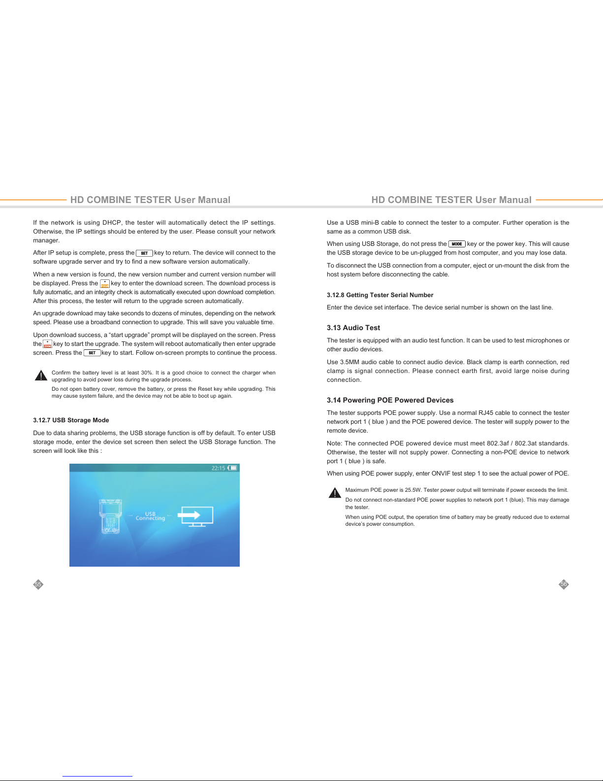
3.12.7 USB Storage Mode
Due to data sharing problems, the USB storage function is off by default. To enter USB
storage mode, enter the device set screen then select the USB Storage function. The
screen will look like this :
HD COMBINE TESTER User Manual HD COMBINE TESTER User Manual
Use a USB mini-B cable to connect the tester to a computer. Further operation is the
same as a common USB disk.
When using USB Storage, do not press the key or the power key. This will cause
the USB storage device to be un-plugged from host computer, and you may lose data.
To disconnect the USB connection from a computer, eject or un-mount the disk from the
host system before disconnecting the cable.
3.12.8 Getting Tester Serial Number
Enter the device set interface. The device serial number is shown on the last line.
3.13 Audio Test
The tester is equipped with an audio test function. It can be used to test microphones or
other audio devices.
Use 3.5MM audio cable to connect audio device. Black clamp is earth connection, red
clamp is signal connection. Please connect earth first, avoid large noise during
connection.
3.14 Powering POE Powered Devices
The tester supports POE power supply. Use a normal RJ45 cable to connect the tester
network port 1 ( blue ) and the POE powered device. The tester will supply power to the
remote device.
Note: The connected POE powered device must meet 802.3af / 802.3at standards.
Otherwise, the tester will not supply power. Connecting a non-POE device to network
port 1 ( blue ) is safe.
When using POE power supply, enter ONVIF test step 1 to see the actual power of POE.
Page 31
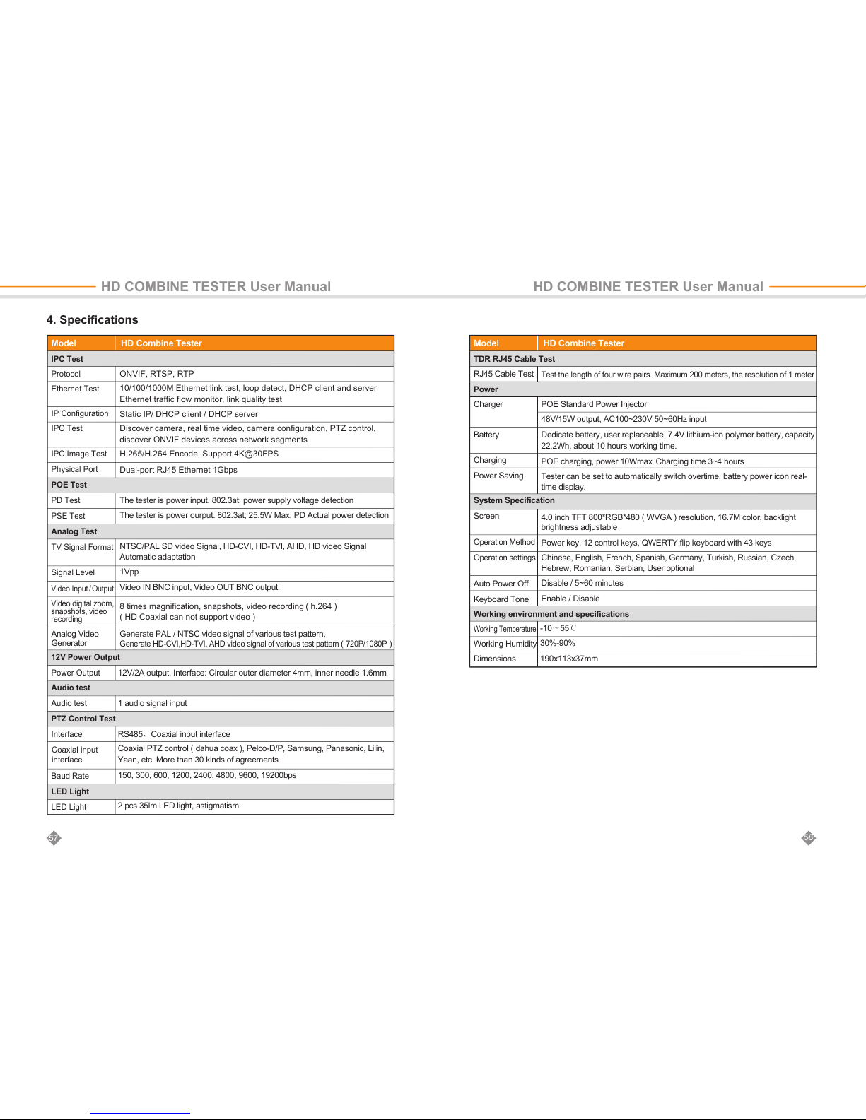
4. Specifications
58
57
Dual-port RJ45 Ethernet 1Gbps
The tester is power input. 802.3at; power supply voltage detection
The tester is power ourput. 802.3at; 25.5W Max, PD Actual power detection
NTSC/PAL SD video Signal, HD-CVI, HD-TVI, AHD, HD video Signal
Automatic adaptation
1Vpp
Video IN BNC input, Video OUT BNC output
8 times magnification, snapshots, video recording ( h.264 )
( HD Coaxial can not support video )
Generate PAL / NTSC video signal of various test pattern,
Generate HD-CVI,HD-TVI, AHD video signal of various test pattern
(
720P/1080P
)
12V/2A output, Interface: Circular outer diameter 4mm, inner needle 1.6mm
RS485、Coaxial input interface
Coaxial PTZ control ( dahua coax ), Pelco-D/P, Samsung, Panasonic, Lilin,
Yaan, etc. More than 30 kinds of agreements
150, 300, 600, 1200, 2400, 4800, 9600, 19200bps
2 pcs 35lm LED light, astigmatism
1 audio signal input
Model
IPC Test
Protocol
Ethernet Test
IP Configuration
IPC Test
IPC Image Test
Physical Port
POE Test
PD Test
PSE Test
Analog Test
TV Signal Format
Signal Level
HD Combine Tester
Test the length of four wire pairs. Maximum 200 meters, the resolution of 1 meter
POE Standard Power Injector
48V/15W output, AC100~230V 50~60Hz input
Dedicate battery, user replaceable, 7.4V lithium-ion polymer battery, capacity
22.2Wh, about 10 hours working time.
POE charging, power 10Wmax. Charging time 3~4 hours
Tester can be set to automatically switch overtime, battery power icon real-
time display.
4.0 inch TFT 800*RGB*480 ( WVGA ) resolution, 16.7M color, backlight
brightness adjustable
Power key, 12 control keys, QWERTY flip keyboard with 43 keys
Chinese, English, French, Spanish, Germany, Turkish, Russian, Czech,
Hebrew, Romanian, Serbian, User optional
Disable / 5~60 minutes
Enable / Disable
-10~55℃
30%-90%
190x113x37mm
Model
TDR RJ45 Cable Test
RJ45 Cable Test
Power
Charger
Battery
Charging
Power Saving
System Specification
Screen
Operation Method
Operation settings
Auto Power Off
Keyboard Tone
Working environment and specifications
Working Temperature
Working Humidity
Dimensions
HD Combine Tester
HD COMBINE TESTER User Manual HD COMBINE TESTER User Manual
ONVIF, RTSP, RTP
10/100/1000M Ethernet link test, loop detect, DHCP client and server
Ethernet traffic flow monitor, link quality test
Static IP/ DHCP client / DHCP server
Discover camera, real time video, camera configuration, PTZ control,
discover ONVIF devices across network segments
H.265/H.264 Encode, Support 4K@30FPS
Analog Video
Generator
Video Input / Output
Video digital zoom,
snapshots, video
recording
12V Power Output
Power Output
Audio test
Audio test
PTZ Control Test
Interface
Baud Rate
LED Light
LED Light
Coaxial input
interface
 Loading...