

Page 1
TR-220
MULTIFUNCTION TEST SET
Transponder, TCAS, DME, TIS, and ADS-B
Test Set
Operational Ma nual
Software Revision 3.40 and Later
REVISION
A B C D E F G H J K L M N
P R S T U V W X Y Z
09 May 2007
Tel-Instrument Electronics Corp
728 Garden Street
Carlstadt, NJ 07072
(201) 933-1600
www.telinstrument.com
Page 2

Leading the AVIONICS TEST industry into the 21st Century!
NOTICE:
The information contained in this manual is subject to change without notice.
Tel-Instrument Electronics Corp. makes no warranty of any kind to this material,
nor shall be liable including but not limited to, errors contained herein or for
incidental or consequential damages in connection with the furnishings,
performance, or use of this material.
Chapter I – Introduc tion
Chapter II – Preparation for Use and Operation
Chapter III – Theory of O per ation
Chapter IV – General Maintenance and Servicing Procedures
Chapter V – Schematics
Chapter VI – Ill ustr ated Parts Catalog
PART NUMBER VOLUMES INCLUDED CHAPTERS INCLUDED
90008088-1 VOLUME 1 CHAPTERS I & II
90008088-2 VOLUMES 1 & 2 CHAPTERS I - VI
COPYRIGHT NOTICE
© 2007 Tel-Instrument Electronics Corp
Reproduction of this publication or any portion thereof by any means without the
express written permission of Tel-Instrument Electronics Corp. is prohibited. For
further information, contact the Customer Support Manager, 728 Garden Street,
Carlstadt, NJ 07072. (201) 933-1600
Page 3
A
Safety Precautions
The following ar e general safet y precauti ons that are not rel ated to a parti cul ar test or pr ocedure.
These are recommended procedures that all personnel must apply during many phases of
operation and m aintenance. It is assumed that the op erator has general knowledge of electrical
theory and the dangers associ ated with it.
1. When performing any of the preceding; thoroughly read and understand all
procedures before ac tually performing t hem.
2. The various front panel connectors, switches, and controls specified can be
located by refer ri ng to Figure 2-1 on page 2-3.
3. Take the time to learn the proper operation and function of the Test Set as
outlined in Chapters 1, 2, and 3. Through knowledge of the Test Set and its
capabiliti es greatly improves the time it t ak es to complete the tests.
4. Pay parti cular attenti on to NOTES and WARNINGS that may accompany some
test and operati onal procedures.
lerts the operator to potential dangers associated with a particular test.
Thoroughly understand the warning before proceeding to prevent a
potentially dangerous situation or dam age to the Test Set.
WARNINGS
NOTE
Provides supplemental informati on that enhanc es the procedure or
further explains in detail additional information to ensure understanding or
5. Observe all standard safety procedures when working with live voltages. The
potential f or electric shock exists any tim e the Test Set is removed from its case.
6. DO- NOT serv i ce the uni t or mak e adjustm ent s alone. Al ways be in t he presence
of another person when working with live voltages.
7. Thoroughly inspect the equipm ent and the local area for potent ial hazards. Loose
clothing and j ewelry should b e removed any time the test set is being ut ilized or
being serviced.
8. Be familiar with general first aid procedures and CPR (Cardiopulmonary
Resuscitation). Contact your local Red Cross f or m ore information.
NOTES
proper operati on.
9. Ensure the test equipment and the tools you utilize are in good operational
condition and not damaged in any way.
10. Use only specified replacement parts as listed in the IPB. Failure t o utilize factory
approved part s may cause damage to person nel; the test set’s, and possibly void
the warranty.
Page 4
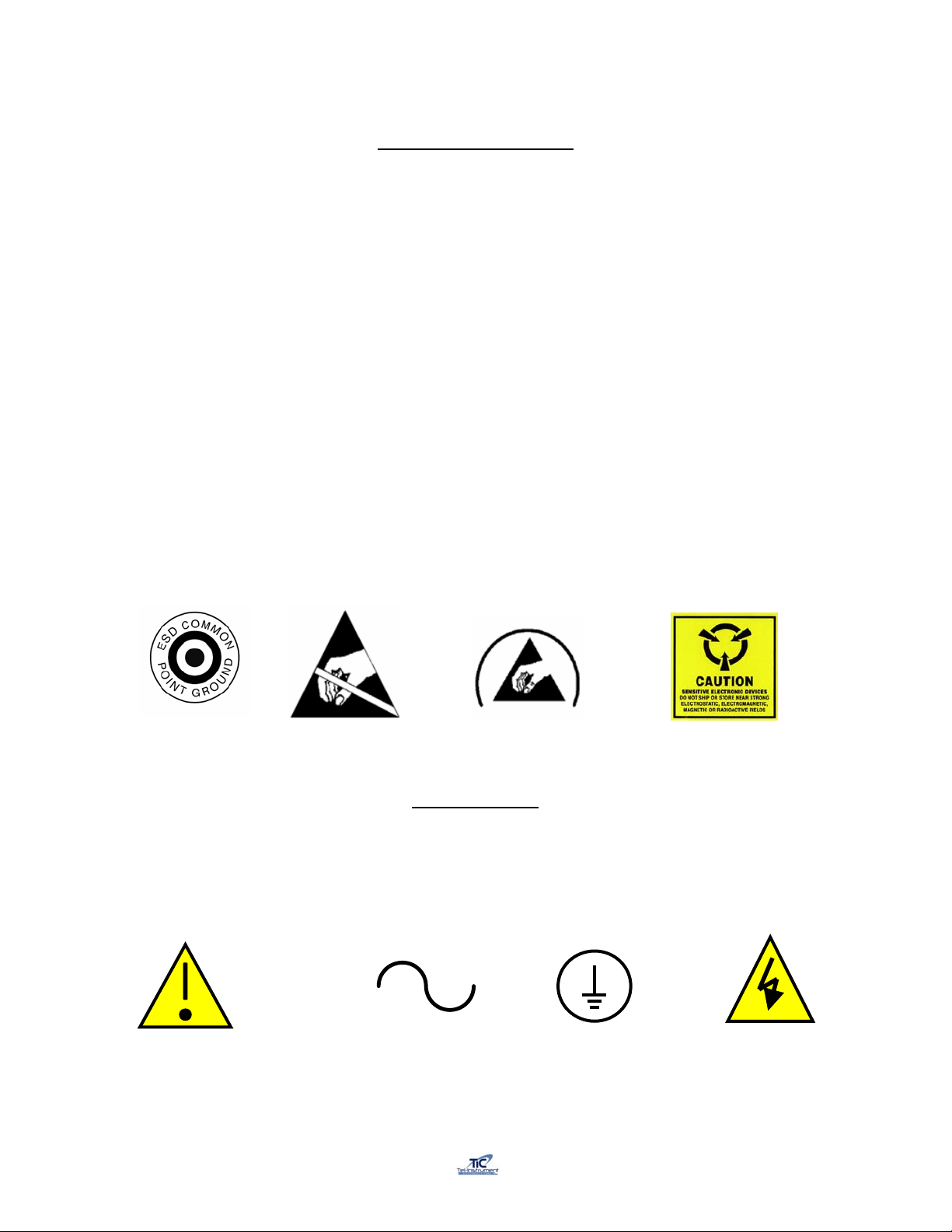
ESD Safety and Protection
Many parts contai ned in the Test Set are sensit ive to ESD (Electro-St atic Discharge) damage.
ESD can damage integrated cir c uits or semiconduct or s l oc ated within the Test Set. Only qual ified
personnel should serv ice the Test S et to prevent damage. The f ollowing are guideli nes to avoid
ESD damage while still performing tests and or maintenance. These guidelines are meant only as
a reminder, consult local directiv es and f ollow standard operat ing pr ocedures bef ore serv i cing, or
repairi ng the T est S et.
• Wear a properly grounded wrist strap and remain in contact with an approved grounding
point.
• Do not touch the connect or pins or back planes of ESD Sensitive circuits or par ts.
• Ensure solderi ng ir ons are grounded before use.
• Do not remove any components or disconnect any connectors locat ed in the Test Set with
the power “ON”.
• Properly ground all test equipment being utilized. Refer to the test equipment operating
manual for information.
• Place all remov ed c om ponents or parts in or on an approved conductive package.
Most ESD devices or circuit s and common points are readily identifi ed utilizing several different
methods. Below are some ex am ples.
The Following S ymbols may be utilized in diff erent locations thr oughout the Manual and ar e also
located on and in the Test Set. Observe these warnings and markings and follow standard
electrical safety anytime you utilize live ci r c uits.
Caution Alternating Current
CE (IEC) Marking
Protective Conductor
Terminal
Caution, risk of
electrical shock
Page 5

VOLUME 1
OPERATIONAL PROCEDURES
Page 6

Rev E TR-220 90 008 088-1
TR-220 TABLE OF CHANGES1
Date REV ECO Page Description
Prelim. Initial Release
07 Sep 03 A Initial Release
15 July 04 B Updated procedure explanations
16 Mar 05 C
2-5 & 6, 13, 17,
22, 43-46
01 Jul 05 D Chapter 3-6 Added CHAPTERS 3, 4, 5, &6
9 May 07 E Chapter 1 and 2
Provided Detailed EHS and ADS setup
and display info
Add test capability for measuring reply
delay, jitter, MS P6 pulse amplitude
variation, and MS P5 pulse width
1
Changes are also denoted with a solid bar in the Left margin of each affected page.
i
Page 7

Rev E TR-220 90 008 088-1
Table of Contents
Chapter Page
Table of Changes……………………………………………………………………. i
List of Illustrations…………………………………………………….……………… vii
List of Tables……………………………………………………….………………… viii
I INTRODUCTION
Section A- General Information
1.1 Scope of Manual…………………………………………………………… 1-1
1.2 Purpose and Function of Equipment…………………… ………… ……. . 1-1
1.3 Regulatory Responsibilities…………………………………………......... 1-2
1.4 Warranty…………………………………………………………………….. 1-3
1.4.1 Obtaining Warranty Service………………………………………… 1-3
1.4.1 Shipping and Packing the T est Set………………………………... 1-4
Section B- Equipment Description
1.5 Specifications………………………………………………………………… 1-5
1.6 Abbreviations, Acronyms, and Glossary of Terms…………………....... 1-7
II PREPARATION FOR USE AND OPERATION
Section A- General Information
2.1 General………………………………………………………………........... 2-1
2.2 Unpacking…………………………………………………………………… 2-1
2.3 Installation…………………………………………………………………… 2-1
2.4 Accessories…………………………………………………………………. 2-1
ii
Page 8

Rev E TR-220 90 008 088-1
Table of Contents (continued)
Chapter Page
Section B- Operating Controls, Indicators, and Connectors
2.5 General………………………………………………………………........... 2-3
2.6 Controls, Indicat ors, and Connectors……………………………………. 2-3
Section C- Operating Instructions
2.7 General………………………………………………………………........... 2-5
2.8 Battery Operation…………………………………………………………… 2-5
2.8.1 Auto-Shutdown………………………………………………….. 2-6
2.9 TR-220 Supplied Ant enna…………………………………………………. 2-6
2.9.1 Directional Antenna…………………………………………….. 2-6
2.9.2 Direct Connect………………………………………………….. 2-9
2.9.3 TAP-200 Antenna Coupler…………………………………….. 2-9
2.10 Initial Startup and Self-Test……………………………………………….. 2-12
2.11 Transponder Test Sequence……………………………………………… 2-13
2.12 Transponder Manual Sequence of Tests………………………………… 2-14
2.12.1 ATCRBS, Mode A/C Manual Testing………………………… 2-14
2.12.2 Mode S Manual Testing……………………………………….. 2-17
2.13 Transponder Automatic Sequence of T ests…………………………….. 2-24
2.13.1 ATCRBS, Mode A/C Automatic Testing……………………… 2-24
2.13.2 Mode S Automatic Testing…………………………………….. 2-26
2.14 Testing a Transponders “IDENT” Function……………………………… 2-28
2.15 TCAS Tests…………………………………………………………........... 2-29
2.15.1 Typical TCAS Concepts……………………………………….. 2-29
2.15.2 TCAS Scenario Selection and Setup …….……… ………….. 2-29
2.15.3 Erasing the TCAS Scenario Memory………………………… 2-35
2.15.4 Testing a TCAS Equipped Aircraft……………………………. 2-36
2.16 DME Tests………………….……………………………………………….. 2-41
2.16.1 DME Setup…….………………………………………………… 2-41
2.17 Mode S Enhanced Surveillance…………………………………………... 2-43
iii
Page 9

Rev E TR-220 90 008 088-1
Table of Contents (continued)
Chapter Page
2.18 ADS-B and TIS Testing……………………………………………………. 2-47
2.18.1 ADS-B TX……………………………………………………….. 2-47
2.18.2 ADS-B RX………………………………………………………. 2-50
2.19 RS-232 Download Procedures…………………………………………… 2-52
2.19.1 Setting Up your Computer for RS-232 Download………….. 2-53
2.19.2 Downloading the Data…………………………………………. 2-54
2.19.3 Loading the Data to a Microsoft Excel File………………….. 2-55
List of Illustrations (Figures)
Figure Title Page
1-1 TR-220 Multifunction Test Set…………………………… ………… …………. 1-1
2-1 TR-220 Accessories…………………………………………………………….. 2-2
2-2 Controls, Indicators, and Connector Locations………………………………. 2-3
2-3 Directional Antenna Gain……………………………………………………….. 2-7
2-4 Directional Antenna Setup……………………………………………………… 2-8
2-5 TAP-200………………………………………………………………………….. 2-10
2-6 TAP-200 Placement…………………………………………………………….. 2-11
2-7 TAP-200 Adjustment……………………………………………………………. 2-11
2-8 Sequence of Tests………………………………………………………………. 2-13
2-9 Caution, Warning, and Collision Areas……………………………………….. 2-29
2-10 Typical TCAS I Display…………………………………………………………. 2-30
List of Tabl e s
Table Title Page
2-1 TR-220 Accessories……………………………………………………………. 2-2
2-2 Controls, Indicators, and Connectors…………………… …………………… 2-4
2-3 Preprogrammed TCAS Scenarios……………………………………………. 2-30
2-4 TCAS Intruder Parameters…………………………………………………….. 2-33
2-5 Additional TCAS Intruder Scenarios…….……………………………………. 2-34
2-6 TIS Intruders…………………………………………………………………….. 2-51
iv
Page 10
Rev E TR-220 90 008 088-1
CHAPTER I
INTRODUCTION
SECTION A
1.1 Scope of Manual
This manual is intended to familiarize the operator with the operating and maintenance
procedures necessary to utilize the TR-220 Multifunction Test Set. Here-in after known as the
T/S, Test Set, or TR-220.
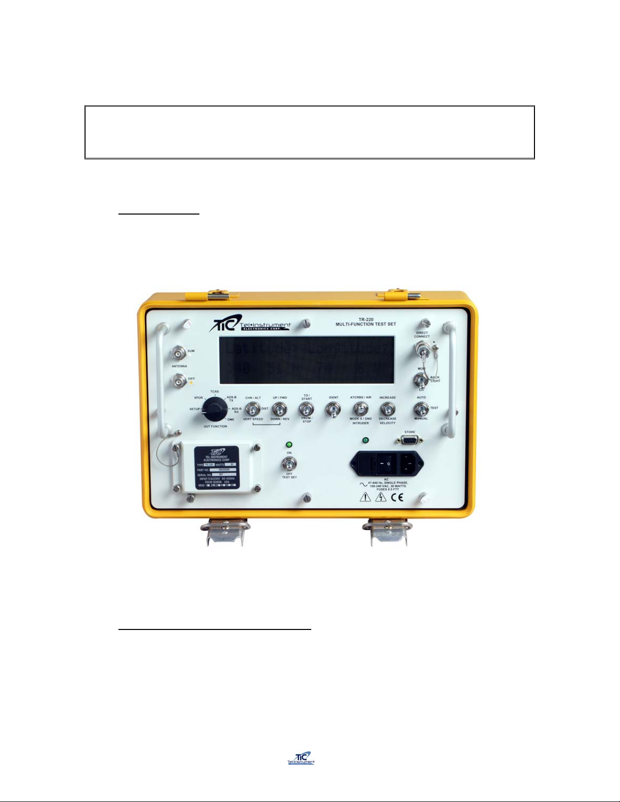
Figure 1-1
TR-220 Multifunction Test Set
1.2 Purpose and Function of the Equipment
The TR-220 Test Set tests airborne ATCRBS, MODE A/C, and MODE S transponders, TCAS I/II
systems, DME equipment, and ADS-B and TIS Transponders. It is self-contained and battery
operated that requires no direct hardware connection to the Unit Under Test (UUT).
For transponder testing, the Test Set simulates secondary radar to receive and radiate signals to
the UUT from antennas supplied with the Test Set. For accurate power and frequency
1-1
Page 11

Rev E TR-220 90 008 088-1
measurements, the Test Set can be directly connected to the UUT without the use of additional
hardware.
For TIS testing, the Test Set transmits simulated Intruder Flight Data, which is then shown on the
TIS display to verify results.
The Test Set will receive and Decode 1090 MHz ADS-B data including squitter type, airborne
position, surface position, aircraft IDENT category, Airborne velocity, Latitude/Longitude,
North/South velocity, and East/W est Velocity. The ADS-B TX function allows the operator to
receive, decode, and display ADS-B squitters. The ADS-B RX function permits the operator to
simulate a 1090MHz squitter. The TR-220 can be configured to transmit an airborne or surface
position squitter containing position, altitude, velocity, heading, aircraft category, flight ID, and
Mode S address.
The simulation of an intruder aircraft converging on the Aircraft Under Test (AUT) accomplishes
TCAS testing. The simulated target will be displayed on the TCAS display so the operator can
ensure proper advisories.
DME tests simulate an aircraft at a simulated speed converging to or from a selected distance. By
comparing the Test Set displayed distance to the DME under test display, the operator can
confirm proper DME operation.
1.3 Regulatory Responsibilities
Effective April 6, 1987, The Federal Aviation Administration (FAA) has required certain tests be
performed on transponders, both conventional ATCRBS and MODE S. In preparation for the
installation of new air traffic control radar facilities, the FAA required new measurements to be
performed on existing transponders and instituted required tests for MODE S transponders. FAR
(Federal Aviation Regulation) Part 43, Maintenance, Preventive Maintenance, Rebuilding and
Alteration section has been modified to reflect current technologies and improvements. TelInstruments has met all FAA requirements and recommends that the user of this type of
equipment review the appropriate FAR or contact the manufacturer of their particular model of
transponder to ensure that the current procedures and limitations are being correctly adhered to.
Eurocontrol has also incorporated new regulations for Mode S Elementary and Enhanced
Surveillance. These requirements include Selective Identifiers for high-density traffic areas and
will become mandatory beginning in May of 2003 for Elementary Surveillance and March 2005 for
Enhanced Surveillance. The TR-220 Test Set has the capability to thoroughly test these new
functions to comply with upcoming requirements. If you would like further information regarding
these requirements, visit www.eurocontrol.int/
.
1-2
Page 12

Rev E TR-220 90 008 088-1
1.4 Warranty
The Tel-Instrument Electronics Corporation warrants that each product it manufactures is free
from defective material and workmanship for a period of two (2) years subject to the following
terms and conditions. Tel-Instrument Electronics Corp. will remedy any such warranted defect
subject to the following:
This warranty requires the unit to be delivered by the owner to Tel-Instrument intact for
examination, with all transportation charges prepaid to the factory, within two (2) years from the
date of sale to original purchaser. Tel-Instrument will solely determine when such defect exists.
This warranty does not extend to any of Tel products which have been subject to misuse, neglect,
accident, improper installation, or used in violation of operating instructions. This warranty does
not extend to units which have been repaired, calibrated, or altered in any way by a facility that is
not approved, in writing, by Tel-Instrument Electronics Corp. to perform such work. This warranty
does not apply to any product where the seals or serial number thereof has been removed,
defaced or changed, nor to accessories not of our own manufacture.
Repair parts will be made available for a minimum period of five (5) years after the manufacture
of this equipment has been discontinued.
This warranty is in lieu of all other warranties expressed or implied and all such other warranties
are hereby expressly excluded. No representative or person is authorized to assume for us any
other liability or warranty in connection with the sale of Tel’s products.
This warranty does not cover or include batteries (batteries have a separate 90 day warranty).
Additional information with regard to the applications and maintenance of this equipment will be
available from time to time.
1.4.1 O btaining Warranty Service
In the event the Test Set may require service or repair that is included under the
warranty provided with the Test Set; the following is necessary to ensure proper
handling:
1. Contact Tel-Instrument Customer Support before shipping any Test Set
back under a warranty condition.
Tel-Instrument Electronics Corp. Customer Support can be reached by
calling:
¾ (201) 933-1600 (telephone)
¾ (201) 933-7340 (fax)
2. The Customer Support Department will discuss the matter and if validated,
issue an RMA (Return Material Authorization) number and form. Do not
return any product without first receiving this authorization.
3. The Test Set must be returned with the completed RMA form. This will
ensure prompt handling and expedited service.
4. Products must be returned in the Original Shipping Container (see
Paragraph 1.4.1). If the original container is no longer available, please
contact Tel-Instrument for guidance. Include in or on the shipping container
the following information:
1-3
Page 13

Rev E TR-220 90 008 088-1
• RMA Form on top of the product
• The assigned RMA number written in bold letters on the
outside of the shipping container
• Model, Serial Number, and specific details regarding the
problem
• POC name, return address, telephone number, and
email address
5. Freight Charges to the factory are the responsibility of the owner/operator.
Tel-Instrument will provide return shipping if the problem is determined to be
warranty covered.
1.4.2 Shipping and Packing the Test Set
1. Repackage the Test Set in the Original container utilizing the provided
packing material. Do Not Ship the Test Set with out using a shipping
container, this will prevent damage to the case and or finish during transit.
2. Wrap the Test set within plastic sheeting and firmly seat the Test Set in
the original corner molds. Place all necessary documentation (RMA Form,
POC, etc…), on top of the Test Set.
3. Utilize Package Tape and seal all seams. If the use of an industrial box
stapler is used, be sure that they do not protrude through the box to
prevent injury to personnel handling the package.
4. Firmly affix a shipping label and mail the Test Set to the following:
Tel-Instrument Electronics Corp.
728 Garden Street
Carlstadt, NJ 07072
Attn: Repair Department
1-4
Page 14

Rev E TR-220 90 008 088-1
SECTION B
EQUIPMENT DESCRIPTION
1.5 Specifications
Transponder Transmitter
Frequency 1030 MHz ± 10 kHz
Output Power >
Modes A, C, S, ADS B TX/RX,
and TIS
4dBm
Transponder Receiver
Accuracy ± 200 kHz
Accuracy ± 2 dB (direct connect)
± 3 dB (radiated)
Accuracy ± 2 dB (direct connect)
± 3 dB (radiated)
Accuracy ± 1%
Frequency Frequency 1086.5 to 1093.5 MHz
Power Range 47 to 64 dBm
Sensitivity Range. -50 to -87 dBm
Reply Percent Range 0 to 100%
DME
DME Receiver
Frequency Frequency Channel Freq +3.5 MHz
Accuracy ± 200 kHz
Sensitivity Range < -35 dB
DME Transmitter
Frequency Frequency 962 to 1213 MHz
Accuracy ± 100 kHz
Power ≥ 4 dB
TCAS
TCAS Transmitter
Frequency 1090 MHz ± 10 kHz
Output Power >
Modes C & S
Antenna Beamwidth…. 15° Sum & Diff Ports
30° Sum only
4dB
1-5
Page 15

Rev E TR-220 90 008 088-1
TCAS Receiver
Frequency 1026.5 to 1033.5 MHz
Power 47 to 64 dBm
Physical Characteristics
Packaging MIL-PRF-28800 Style C
Size 14.5 x 9.4 x 6.5 inches
Weight. 20 pounds
Operating Temperature -28° to +55° C
Battery Operation. 8 hours at a 20%
Duty Cycle
AC Operation/Charging 100 – 240 VAC
47 – 440 Hz
1-6
Page 16

Rev E TR-220 90 008 088-1
1.6 Abbreviati ons, Acronyms and Glossary of Term1
A/A Air to Air
A/A B Air to Air Beacon
ac or AC Alternating Current
A/D Analog to Digital
ADS-B Automatic Dependent Surveillance - Broadcast
Address The unique code to which a MODE S transponder replies. This is not to
be confused with the 4096 code used for identifying ATCRBS
transponders. The address of a MODE S transponder is not alterable by
the pilot or crew.
Altitude The pressure altitude of the aircraft as transmitted by an ATCRBS or
MODE S transponder. This information is obtained from an external
sensor and transmitted to the transponder.
AM Amplitude Modulation
ATCRBS Air Traffic Control Radar Beacon System
ATCRBS/MODE S All Call Interrogation that causes all ATCRBS/MODE S transponders to reply.
ATC Air Traffic Control
AUT Aircraft Under Test
BIT Built in Test
Comm Refers to the communications and data-link capability of a MODE S
transponder. There are four (4) capabilities: No Comm, Comm A/B,
Comm A/B/C and Comm A/B/C/D. The Comm. capability is displayed
when the transponder is determined to be a MODE S.
CW Continuous Wave
D/A Digital to Analog
DAP Downlinked Aircraft Parameter
dB Decibel
dBm Decibels above 1 milliwatt
dc or DC Direct Current
DME Distance Measuring Equipment
DPSK Differential Phase Shift Keying. The method of modulation used for the
selective MODE S uplink interrogations.
DF Downlink Format. The format included in a MODE S transponder reply to
an interrogation or squitter message that indicates the type of message.
ELM Extended Length Messages
FAA Federal Aviation Administration
FAR Federal Aviation Regulation
FIFO First In First Out
FREQ Frequency
ft. Feet
G/A Ground to Air
Hz Hertz
IF Intermediate Frequency
IFF Identify Friend or Foe
KHz Kilohertz
kts. Knots
LCD Liquid Crystal Display
LED Light Emitting Diode
1
Further definitions may be f ound in the following reference books and documents: Helfrick, A.D. Principles of Avionics.
Leesburg: Quality Books, 2000. RTCA/DO- 181B. Minimum Operation al Performance Standards for Air Traffic Control
RADAR Beacon System/Mode Select (ATCRBS /Mode S) Airborne E quipment. W ashington D.C.: 1999. United States.
Federal A viation Administration. Federal Register Fed 3
, 1987 FAA rules Part 91.
1-7
Page 17

Rev E TR-220 90 008 088-1
MODE S A secondary radar system where transponders can be individually
interrogated or selected (the “S” in MODE S) so that in a crowded air
traffic area, the amount of interference or garble can be reduced to a
minimum.
MHz Megahertz
nmi. Nautical mile
ns Nanosecond
PAM Pulse Amplitude Modulation
PDME Precision Distance Measuring Equipment
PMCS Preventative Maintenance Checks and Services
PPM Pulses per Minute
PRF Pulse Repetition Frequency
PW Pulse Width
PWR Power
RA Resolution Advisories
Receiver Efficiency The Test Set’s Measurement of valid replies received. Displayed as a
Percentage.
Reply Codes A transmitted response, from the airborne transponder, to an
interrogation. Commercial transponders responses are designated as
either ATCRBS/A where the reply includes the pilot selected 4096 ID
code, or ATCRBS/C, where the reply includes the aircraft pressure
altitude. These same responses for military transponders are designated
as MODE 3A and MODE 3C. See Mode S for further information.
RF Radio Frequency
RMS Root Mean Square
R/T Receiver Transmitter
SIF Selective Identification Feature
SLS Side Lobe Suppression. A pulse transmitted from an omni-directional
antenna used as a reference level to prevent replies to interrogations
received from the secondary radar antenna side lobes.
Squitter The self-generated transmissions made by a MODE S transponder, not in
reply to an interrogation, for the use of the collision avoidance system.
And ADS-B Receivers and Transmitters.
SSR Secondary Surveillance Radar
Surveillance Altitude An interrogation that causes only the addressed MODE S transponder to
reply.
Surveillance ID An interrogation that causes only the addressed MODE S transponder to
reply to its “4096” code.
TA Traffic Advisories
TACAN Tactical Air Navigation
TCAS Traffic Alert and Collision Avoidance System
TIS Traffic Information System
TX Transmitter
UF Uplink Format. The format in a MODE S interrogation that indicates the
type of reply expected.
VORTAC VOR and TACAN (co-located)
VOR VHF Omni-Directional Range
VSWR Voltage Standing Wave Ratio
WOW Weight On Wheels
UUT Unit Under Test
XPDR Transponder
XPDR UT Transponder Under Test
4096 Code This refers to the octal number dialed into either an ATCRBS MODE A or
MODE S transponder by the pilot. This is to be distinguished from the
address of the MODE S transponder, which cannot be changed.
1-8
Page 18

Rev E TR-220 90 008 088-1
CHAPTER II
PREPARATION FOR USE AND OPERATION
SECTION A
GENERAL INFORMATION
2.1 General
This Chapter contains all nec es sary inform ation on the initial unpacking, inspection, and set-up of
the TR-220 Multifunction Test Set (Herei naft er call ed the TR-220, Test Set, or T/S).
2.2 Unpacking
When receiv ing the TR-220 for the fi rst time, ensure that there is no damage to the shipping
container. Carefully unpack the unit and save the shipping container in a safe location for
shipping or ext ended stor age.
Examine the unit for obvious signs of damage. Check all displays, switches, and connectors
before utilizing the Test Set.
If any dam age i s found, DO NOT use the T est S et until a deter m ination of the Test Sets functions
can be assessed. Contact Tel-Instrument as soon as possible for further instruc tions.
The TR-220 Test Set batt eri es were installed and fully charged when shipped from the factor y .
2.3 Installation
The Test Set is fully func tional and ready to use from the fact or y. There ar e no inst allation
procedures applicable.
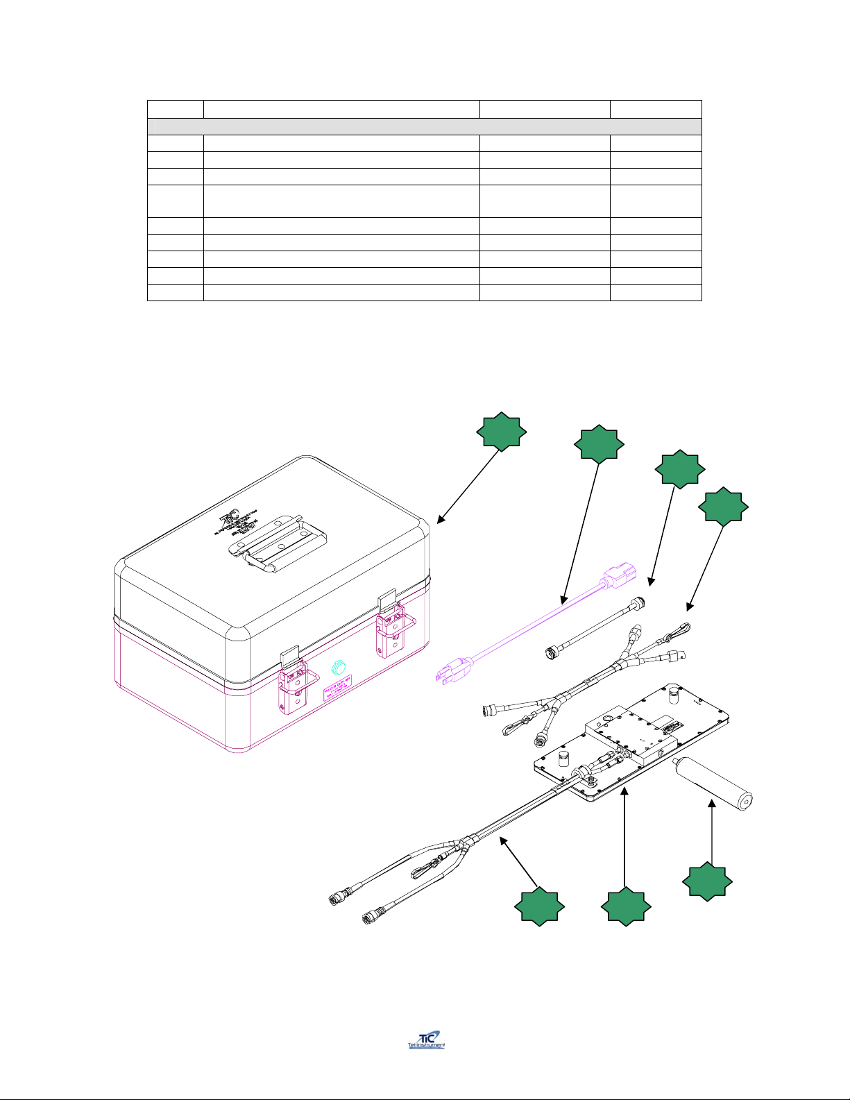
2.4 Accessories
Once opening the Test S et Cover , ensure al l the accessories that were purcha sed with the Test
Set are account ed for. T he TR-220 c om es standard with the following (See next page):
2-1
Page 19
Rev E TR-220 90 008 088-1
# NOMENCLATURE P/N QTY
1 Test Set 90000088 1
2 Cable Assembly, AC Power Cord 75010025 1
3 Cable Assembly, Direct Connect 75010186 1
4 Extender Cable Assembly, Dir ectional
Antenna
75010078
1
5 Directional Antenna Cabl e Assembl y 75010208-02 1
6 Directional Antenna Assembly 89001158-07 1
7 Directional Antenna Handl e A ssembly 88001002 1
X TAP-200 Antenna Coupler Optional
XX TR-220 Manual (Not Shown) 90008088-1 1
TR-220 Accessories
Table 2-1
1
2
3
4
7
6 5
TR-220 Accessories
Figure 2-1
2-2
Page 20
Rev E TR-220 90 008 088-1
SECTION B
OPERATING CONTROLS, INDICATORS, AND CONNECTORS
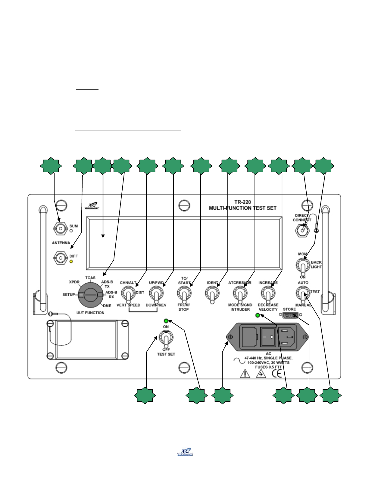
2.5 General
This section c overs loc ation and funct ion of the operat ing c ontrols, indicators, and connectors. Al l
controls, indicators, and connectors are located on the front panel of the T est S et.
2.6 Controls, Indicators, and Connectors
Figure 2-2 and Table 2-2 indicates the location and the f unct ion of each item on the front panel of
the Test Set.
1 2 3 4 5 6 7 8 9 10 11 12
Controls, Indicators, and Connectors
Figure 2-2
2-3
131415 1618 17
Page 21

Rev E TR-220 90 008 088-1
FIG # Control, Indicator, or
Connector
(Table 2-2) FUNCTI O N
1 SUM Antenna Port
2 DIFF Antenna Port Provides Connection to the Directional Antenna Diff Connector
3 Data Display Window
4 UUT FUNCTION Switch
CHN/ALT, DIST, VERT
5
SPEED Switch
UP/FWD, DOWN /RE V
6
7
8 IDENT Switch Initiates a SPI Pulse for verification of transponder IDENT function.
9
10
11 Direct Connect Port
12
13
14 STORE connector RS-232 port for download of stored data to a PC.
15 Test Set charging indicator Indicates to operator that the Test Set Batteries are charging
16 AC Power Panel
17
18 Power ON “LED” Indi cates to the operator that the Test Set is “ON”.
Switch
TO/START – FROM/STOP
Switch
ATCRBS/AI R, MODE S /GND
INTRUDER Switch
INCREASE/DECREASE
VELOCITY
MOM/BACK LIGHT/ON
Switch
AUTO/TEST/MANUAL
Switch
TEST SET ON/OFF
Switch
Provides Connection to the Directional Antenna Sum Connector and the
optional TAP-135 Antenna Coupler.
Alpha/Numeric display (2 lines/20 characters) providing operational
instructions, error messages, scenario progress, and test results.
Provides access to Test Set Menus and Modes.
SETUP- Set Antenna Gain, T/S Distance, TCAS Scenario Selection, Altitude,
Velocity, and Vertical Speed and Distance, Power display (watts or dBm),
Cable Loss, Mode S address, and Latitude and Longitude for ADS-B
Functions.
XPDR- Access ATCRBS and MODE S Transponder test menus.
TCAS- Access TCAS intruder menus.
ADS-B TX- Select ADS-B Transmitter Results.
ADS-B RX- Select ADS-B, and TIS Functions.
DME- Access DME Test menus.
DME- Allows selection of DME Channels. Selectable from 108. 0 MHZ in 50
KHz steps. Used in conjunction with UP/FWD – DOWN/REV switch.
TCAS- Set Intruder altitude offset from 99,900’ t o 50,200’ in 100’ inc/ 50,175’
to -9000’ in 25‘ increments. Default is 0’. Used in conjunction wit h UP/FWD –
DOWN/REV switch.
TCAS- Intruder vertical speed in “feet per minute” (fpm) adjustable in 100’
increments from +7500’ to -7500’. Used in conjunction with UP/FWD –
DOWN/REV switch.
Used in conjunction with CHN/ALT, DIST, VERT SPEED switch to vary
parameters. Also used to set ant enna gain and Test Set di stance in SETUP
mode.
Start and Stop TCAS Intruder scenarios and change DME To/From
parameters.
Selects TCAS Intruder Type (MODE S or ATCRBS), and Air or Ground
position.
Sets TCAS Intruder and DME speed velocities. Also utilized for ADS-B TX/RX
Functions.
For direct connection to a Transponder. Provides accurate RF Power,
frequency and sensitivity measurements.
Activates display backlighting either “ON” or momentarily.
Allows the operator to select an Automatic Sequence of Transponder tests or
a Manual sequence. Initiates TCAS and DME scenarios. Hold AUTO key
when Test Set power is turned “ON” to select CW operation. Use AUTO and
MANUAL to advance through EHS and ADS-B tests.
1. Provides connection to a 115 or 220 VAC power source.
2. AC “ON” / “OFF” switch for battery charging.
3. Fuse Cartridge.
Turns Test Set “ON” and “OFF”.
2-4
Page 22

Rev E TR-220 90 008 088-1
SECTION C
OPERATING INSTRUCTIONS
2.7 General
The TR-220 i s a self-cont ained instrum ent comprised of a Test Set mounted in a r ugged case
with a removable cover. The Test Set front panel contains all the switches necessary to test
Transponders (ATCRB S and MO DE S), ADS- B and TIS , DME and TCAS equipm ent. By t he use
of toggle switches and an easy to read display, the operator m ay quickly test, make accurate
measurements and perform preprogrammed or manually selected TCAS scenarios. The
directional antenna with an active LED display and optical sight are utilized for Transponder,
DME, and TCAS tests. All accessories are stored in the Test Set case for easy storage and
protection.
2.8 Battery Operation
The TR-220 Test S et is equipped with a rechargeable Lead Acid batter y , capable of operating the
Test Set using a 20% dut y cycle f or 8 hours at 77 degrees F (25 Degree s C). This repre sents a
full day of t ypical t esti ng on a si ngle c harge. W hen operat ing t he Test S et i n l ower tem perat ures,
the battery life will decrease slightly .
The operator will be able to utilize the Test Set until the batteries are nearl y depleted. The unit
may then be plugged i nto a standard 115 or 220 VAC / 47 to 440 HZ power source to conti nue
testing. By observi ng a Duty Cycle (DC) of 20%, the Test Set batteri es will begin regaining their
charge while testing is in progress.
The TR-220 provi des a low battery warning system to alert the operator when batt ery strength
has been deplet ed to a poi nt where t esti ng m ay be i nter rupted. Sev eral warni ng are di splayed t o
warn the operator of this condition and to give them a warning that the batteries will require
charging or supplem ental AC power applied to complete ext ended testing.
As the battery capacity decreases, the Test Set will displ ay the following:
Toggle the AUTO switc h to bypass the di spl ay and continue testing. A pproximately 15 minutes of
battery capaci ty is available. As the batter y strength decreases, the di spl ay will indicate:
This indi cates only several minutes of t esti ng time is a v ailable. It i s recomm ended that AC power
be supplied t o continue testing or testing halted at this point and the Test Set charged. Toggle the
AUTO switch to bypass thi s warning. Further t esting will result in the final warni ng:
Low Battery
Press AUTO to cont.
Low Battery
Recharge Required!
Low Battery
SHUTTING DOWN
2-5
Page 23

Rev E TR-220 90 008 088-1
This warning cannot be bypassed, and AC power must be utilized or charging the battery is
necessary.
It is strongly r ec om mended that t he batteries be charged for a short tim e eac h week, r egar dless if
the Test Set has be en utili zed or not. A completely discharged batt ery will require approximat ely
16 hours to fully c harge. Occasional char ges of 16 hours on partiall y depleted bat teries will have
no adverse effec ts.
The current batt er y status display is available in t he SETUP f unction.
T o preserv e batter y strengt h, the TR-220 will autom atically shut down af ter 20 minutes of
inactivity. By toggling any switch during the 20 minutes will reset the timer allowing
extended testi ng.
Shutdown will not occur when AC power is utilized as the source.
2.9 TR-220 Supplied Antenna
Standard equipm ent with the TR-220 is a Directional Antenna. The antenna, stored in the case
cover, can ei ther be hand held, tripod m ounted, or directl y mounted on the Test Set c ase. The
Test Set also contai ns a direct connect cable for accurate power and f requency measurements
(± 2 dB) when connec ted directly to the UUT . The Test Set has a buil t in 50 dB attenuator to
prevent dam age to t he Test Set due t o the High Power RF associated with Transponders.
Battery: EF
Cont: AUTO
2.8.1 Auto Shutdown
2.9.1 Directional Antenna
The Directional Antenna is a printed circuit sandwiched between two opaque Lexan
sheets.
1. Open and rem ov e the TR-220 T est Set c ase cov er. Release the t wo (2) push b utt on
holders
2. The Directional Ant enna can be mount ed on the case or be hand-held ut ilizing the
supplied handle.
2a. To m ount the antenna to t he case, simpl y slide the m ounting Tabs (located on
the back) into the slots located on the front of the Test Set Case.
2b. To utili ze the hand hel d met hod, att ach the suppli ed handl e to the bott om of the
antenna and hand tight en only.
2c. You may also att ach t he antenna t o a tri pod, which will i nc rease the stabil it y due
to high winds or hand movement thus increasing the lock on rat e.
3. The operator m ust fi rst set the pr oper Ant enna Gai n v alue i nto the T est Set memory .
Turn the Test Set “ON” with the UUT FUNCTION switch in the SETUP position.
2-6
Page 24

Rev E TR-220 90 008 088-1
Locate the ANT GAIN menu by toggling the AUTO/MANUAL switch. Enter the
correct val ues that are affixed to the Di rectional Antenna (Figure 2-3) by using the
UP/FWD, DOWN/REV switch. Ensure you enter both values, 1030 MHz and 1090
MHz. Once completed, turn “OFF” the Test Set. The values will remain in the Test
Set memory. You will only need to reenter the values if the antenna i s replaced or
repaired.
Ant Gain 1030: +XXdB
Chg:Up/Dn Cont: AUTO
Directional Antenna Gain
Figure 2-3
4. When using the handheld or tripod method, connect the extender cable supplied with
the Test Set, ensuring to match the appropriate color-coded cables. Connect the
opposite ends of the ANTENNA SUM & DIFF connectors on the Test Set front
panel. If rev ersed, the Test Set will displ ay a fault prompting t he operator to check
their antenna connections.
ANTENNA Connections
ANTENNA DATA
Gain @ 1030 Gain @ 1090
-XX dB -XX dB
Missing or Reversed
5. Maint ain a 10 to 170 ft. (3 to 50 meters) unobstructed path t o the Aircr aft Under Test
(AUT), and point t he Dir ectional antenna to the appropriate antenna on the AUT.
6. Turn the Test Set “ON” wit h the UUT FUNCTION switch in SETUP. Locate the T/S
Distance menu by toggling the AUTO switch and insert the approximate distance
measured from the Test Set to the AUT antenna by toggling the UP/FWD,
DOWN/REV switch. With out turning the Test Set OFF, turn the UUT FUNCTION
switch to the desired sequence of tests.
T/S Distance: 170 ft
Chg: Up/Dn Cont:Auto
7. The optical sight will have a blinking LED indicating the operator must turn the
antenna sli ghtly to gain a strong RF signal. A steady red LED signif ies a good RF
signal and the Test Set will commence testing. The operator may also observ e the
TURN indicator located on t he display. By slowing turni ng the antenna, the TURN
indicator will spin slower until a lock is obtained. At that point, the Test Set will
display the appr opr iate display.
2-7
Page 25

Rev E TR-220 90 008 088-1
NOTE: The TR-220 uses a software technique to n arrow the beam widt h. When
testing inside of a hanger, multi-path reflections can cause erroneous TURN
indications. If unable to eliminate TURN message, remove antenna cable
connection t o DIFF port. Thi s will not affect any test results.
8. Positi on the antenna wit h an unobstruct ed line t o the UUT antenna. Ensure that the
transmitt er or receiver (RX/TX) that you are testi ng is signif icantly cl oser to the T est
Set than another operating RX/TX; else, an undesired reply or erroneous and
inaccurate results may occur.
Directional Antenna Setup
Figure 2-4
M eas ur em en t s util iz in g t h e Dir ec ti on al A nt en na have an acc uracy of ± 3 dB.
2-8
Page 26

Rev E TR-220 90 008 088-1
2.9.2 Direct Connect
The Direct Connect Cable, supplied with the Test Set, allows the operator to conduct
transponder tests directly from the transponder under test. Utilizing the direct connect
method eliminates possible antenna and cable losses and ensures the operator the
transponder is operat ing at its full potenti al. The TR-220 has a built in 50 dB attenuat or,
thus eliminating the need to connect an external attenuator for power and frequency
m easurem ent s. Simply connect the suppl ied c able from t he test set t o the transponder t o
be tested. Ensure that if your tr ansponder has m ultiple ant ennas (div ersit y equipped), to
terminate t he second ant enna to prevent damage to the transponder.
If you are not using t he Direct Connect method, but the directi onal antenna m ethod, you
must install the supplied termination cap on the DIRECT CONNECT port. If it is not
properly installed, the Test Set display will prompt the operator to remov e the ant enna.
Before testing utilizing the supplied Direct Connect cable, the operator must enter the
appropriate c able loss to ensure accurate measurements.
1. Access the ANT GA IN m enu by turni ng t he Test Set “ON” with the UUT FUNCTION
Direct Connection
REMOVE ANTENNA
switch in the SETUP position. Locate the Cable Loss menu by toggling the
AUTO/MANUAL switch. Enter the correct values that are affixed to the supplied
cable by using t he UP/FWD, DOWN/REV switch. If you are using a different cable, it
is important to know the cable loss value or inaccurate results will occur. Once
completed, t urn “OFF” the Test Set or toggl e to AUTO switch. The value will remain
in the Test Set m emory. You will only need to reent er the value if another cable is
utilized or it is repaired.
2.9.3 TAP-200 Antenna Coupler (Optional)
The TR-220 can be used wit h the ( opti onal) T AP-200 Ant i Radiati on Ant enna Coupler for
testing transponders (fig 2-5). The Antenna couplers provide a limited amount of
attenuati on, approximately 20 dB, to prev ent the transmission of the tr ansponder signal
into the airspace above the aircraft under test. The Antenna Couplers may only be
utilized on bl ade ty pe antennas.
Cable Loss: 1.8 dB
Chg: Up/Dn Cont:AUTO
Measurements utilizi ng the direct c onnect method have an acc uracy of ± 2 dB.
2-9
Page 27

Rev E TR-220 90 008 088-1
TAP-200 Coupler
Figure 2-5
1. Connect the TAP-200 Cable to the TR-220 antenna SUM port.
2. Turn the test set ON by toggling the ON/OFF switch Up and turn
the UUT FUNCTION switch to the SETUP position. Scroll to the Antenna
Selection screen usi ng the AUTO/MANUAL switch.
Antenna: TAP
Chg:Up/Dn Cont:AUTO
3. Use the UP/FWD-DOWN/ REV switch to select TAP.
4. To install the coupler, pull the ring, which separates the spri ng- loaded clamp, and
slide the coupler over the blade antenna. Ensure that the EMI gasket of the
coupler is flush with the aircraft skin and that the coupler is centered over the
antenna. Release the ring (fi g 2-6).
5. Ensure that the coupler is centered ov er the antenna to be tested.
6. Due to the availability of numerous styles of antennas, slight adjust of the
Coupler may be necessary to receive accurate measurements. If incorrect
r eadings occur , r e-posit ion and ensure a snug f it on the antenna. Mov e t he TAP 200 forward or back and double check a firm and snug seal on the aircraft
surface (fi g 2- 7).
7. An accurate adjust of the couplers can be accomplished by advancing to the
Manual Mode of tests POWER, RECEIVER, FREQ test page and adjusti ng the
coupler for the maximum power out. O nc e adjusted, the operat or can then restar t
the appropriate series of tests ensuring accurate results.
2-10
Page 28

Rev E TR-220 90 008 088-1
Center the TAP-200 as close to center
as possible for the style of antenna
being tested. If inaccurate results
occur, reposition the coupler slightly
forward or back and check for a snug
flush fit until accurate measurements
are displayed. Due to the many styles
of antennas available, adjustments
may be necessary.
TAP-200 Placement
Figure 2-6
Power, Receiver, Freq
54 dB -77 dB 1090.0
TAP-200 Antenna Adjustment
Figure 2-7
.
8. Proceed with Transponder testing as outlined in paragraph 2.12 or 2.13
2-11
Page 29

Rev E TR-220 90 008 088-1
2.10 Initial Startup and Self-Test
When using t he Test Set, it is advi sable to have a f ully charged battery . This will ensure al l test s
can be complet ed with no int er r uptions or loss of data.
1. Turn on the TR-220 by toggling the ON/OFF switch “UP”. The green LED located
above the switch will illuminate. Briefly, the Test Set display will indicate: Model number,
current software version install ed and tot al hours of operation.
2. The Test Set will immediately commence a SELF TEST.
The Self Test function is automatic, and will test the following components:
a. Digital Board
b. RF Maximum Power
c. RF Minimum Power
d. RF Board
If a failure is detected, a message indicating the failed component or test will be
di splay ed. If no f ailures are det ected, t he result will be briefl y displayed bef ore movi ng to
the initial star t page of the selected tests.
3. Toggle the BACKLIGHT switch to the MOM position and verify the Test Set display
backlighting illuminates. Release the switc h and the backlighting will extinguish.
4. Turn the T est Set “O FF” by toggli ng the ON/OFF switch down. The display will be blank
and the green LED will extinguish.
Tel-Instrument TR-220
REV X.XX 00001 hrs
Self Test
Testing . . .
Self Test
PASS
2-12
Page 30

Rev E TR-220 90 008 088-1
2.11 Transponder Test Sequence
The TR-220 T/ S i s capable of testi ng ATCRB S Mode A, Mode C an d Mode S tr an sponders. T he
operator m ay select bet ween an Automatic series of tests and a Manual series of t ests. Figur e 2-
8 outlines t he sequ ence, i n order , of t ests c onducted. The T est Set will determine the correct set
of tests, either M ode A/C or Mode S upon rec eiv ing the transponder RF signal.
Transponder Sequence
Figure 2-8
2-13
Page 31

Rev E TR-220 90 008 088-1
2.12 Transponder Manual Sequence of Tests
NOTE
When conducting tests in the MANUAL sequence, the operator initializes the sequence by
toggling the AUTO/TEST/MANUAL switch to the MANUAL position. The Test Set then
commences a series of tests and displays the individual results of each test (see figure 2-8)
ending in the POWER, RECEIVER EFFICIENCY and FREQUENCY page. After each test is
completed, the operator must toggle the MANUAL switch to advance to the next test in the
series.
The “IDENT” feature of a t ransponder can onl y be t ested dur ing t he MANUAL seque nce of t ests.
See paragraph 2-14 for detailed instructions.
2.12.1 ATCRBS, Mode A/C Manual Testing
1. Utilize the procedures as outlined in paragraph 2.9 to select the preferred
antenna method for the following tests.
2. Turn the Test Set “ON” by toggling the ON/OFF switch to the ON position.
3. The Test Set commences the Self Test. “PASS” i s displayed bri efly if no fail ures
4. Turn the UUT FUNCTION switch to the XPDR position. The Test Set will
automatically determine the transponder capability as being Mode A and/or C
capable and displ ay the appropr iate start page.
5. Toggle the AUTO/TEST/MANUAL switch to the MANUAL position to begin t he
All illustr ations shown are for demonstrati on pur pose s. Though the test
results may be typic al, they are not meant to replace FAA guidelines and
Ensure the green LED illuminates.
are detected.
manufacturer r ec ommendations.
Self Test
PASS
Capab Mode A/C
Press A/M
sequence.
M A /
Mode A Test initialized.
Testing . . .
2-14
Page 32

Rev E TR-220 90 008 088-1
A
A
g
6. To adv anc e, toggle the AUT O/TEST/MANUAL switch to MANUAL. The next test
in sequence will commence.
7. To adv anc e, toggle the AUT O/TEST/MANUAL switch to MANUAL. The next test
in sequence will commence.
8. To advance, toggle the AUTO/TEST/MANUAL switch to MANUAL. The next t est
in sequence will commence.
M A 1234 100%
0.45–20.35– 0.45 PASS
M A Rply 3.11us P
M A Jitter 25ns P
M C /
Testing . . .
M C 6520 10000’ 100%
0.45 – 20.35 – 0.45 PASS
M C Rply 3.11us P
M C Jitter 25ns P
Mode A SLS Τ
Testing . . .
SLS P1>P2 100% PASS
P1=P2 0% PASS
Sensitivity
Testing . . .
Test Complete. Display indicates the UUT
4096 Octal Code (1234), Receiver
Efficiency as a percentage (100%),
Transponder Framing Pulse widths (0.45)
and separation measured in .05 µs
increments (20. 35 µs).
n alternati ng display indicates the Mode A
Reply Delay and Jitter with a P(ass) or
F(ail) indic ation for each measurement.
Mode C Test initializ ed.
Test Complete. Display indicates the UUT
Altitude Gray Code (6520=1000’), Rcvr.
Efficiency as a percentage (100%),
Transponder Framing Pulse widths (0.45)
and separation measured in .05 µs
increments (20. 35 µs).
n alternating display indicates the Mode
C Reply Delay and Jitter with a P(ass) or
F(ail) indic ation for each measurement
Mode A SLS tests are initiated. The test
set makes alternating interrogations with
and without the SLS pul se.
When P1>P2 (S LS pulse at P1 - 9dB) the
transponder reply efficiency should be
greater than 99%. For P1=P3 (SLS) The
transponder repl y effi ciency should be l ess
than 1%
UUT Receiver sensitivity tests (MTL) for
modes A and C are initiat ed.
** Deno tes a test only a vail able with
Software Revision 5.00 or
**
.**
reater.
2-15
Page 33

Rev E TR-220 90 008 088-1
9. To adv anc e, toggle the AUT O/TEST/MANUAL switch to MANUAL. The next test
in sequence will commence.
NOTE
A: -73.9dB C: -73.9dB
Sens. A&C: PASS
Power, Frequency /
Testing . . .
Power, Frequency
54 dB 1090.0 MHz
Power measurement s are measured in Watts or dBm. The Test Set only
displays dB due to display restrictions. To change the display to indicate
Watts, access the SETUP menu and toggle to the Power in Watts menu.
Use the UP/DOWN toggle to make a selecti on.
END OF MODE A/C MANUAL TESTS
Test Completed. Displ ay indi cates the UUT
receiver sensitivity for mode A (-73.9db)
and Mode C (-73.9dB) PASS is displayed
when Mode A/C sensitivities are within
1dB.
UUT Power and Frequency Test is
initialized.
Test Completed. Displ ay indi cates the UUT
power (54 dB) and Frequency (1090.0) i n
MHz.
2-16
Page 34

Rev E TR-220 90 008 088-1
A
g
2.12.2 Mode S Manual Testing
1. Turn the Test Set “ON” by toggling the ON/OFF switch to the ON position.
Ensure the green LED illuminates. Utilize the procedures as outlined in 2.9 to
select the preferred antenna method for the f ollowing tests.
2. T he Test Set commences the Self Test. “P ASS” is di splayed briefly if no failures
are detected.
3. Turn the UUT FUNCTION switch to the XPDR position. The Test Set will
automatically determine the transponder capability as being Mode S capable and
di splay the appropriate start page wit h the COMM A, B, C, & D capabilities also
listed. The Test Set will display if the transponder reports it is capable of
Enhanced Surveillance (EHS). The Test Set will display the Vertical Status
(Air/Gr ound) and displ ay the results of an Interrogation Identifier (14) test.
4. Toggle the AUTO/TEST/MANUAL switch to the MANUAL posit ion to begin the
sequence:
5. To adv anc e, toggle the AUT O/TEST/MANUAL switch to MANUAL. The next test
in sequence will commence:
Self Test
PASS
Capab Comm AB EHS
AIR Press A/M II:14
M A /
Testing . . .
M A 1234 100%
0.45–20.35– 0.45 PASS
M A Rply 3.11us P
M A Jitter 25ns P
M C /
Testing . . .
Mode A Test initialized.
Test Complete. Display indicates the UUT
4096 Octal Code (1234), Receiver
Efficiency as a percentage (100%),
Transponder Framing Pulse widths (0.45)
and separation measured in .05 µs
increments (20. 35 µs).
n alternati ng display indicates the Mode A
Reply Delay and Jitter with a P(ass) or
F(ail) indic ation for each measurement.
Mode C Test initializ ed.
** Deno tes a test only a vail able with
Software Revision 5.00 or
**
reater.
2-17
Page 35

Rev E TR-220 90 008 088-1
A
A
g
6. To adv anc e, toggle the AUT O/TEST/MANUAL switch to MANUAL. The next test
in sequence will commence:
7. To advance, toggle the AUTO/TEST/MANUAL switch to MANUAL. The next t est
in sequence will commence:
8. Toggle the AUTO/TEST/MANUAL switch to MANUAL to advance to the next
sequence:
9. Toggle the AUTO/TEST/MANUAL switch to MANUAL to advance to the next
sequence:
M C 6520 10000’ 100%
0.45-20.35-0.45 PASS
M C Rply 3.11us P
M C Jitter 25ns P
Mode A SLS /
Testing . . .
SLS P1>P2 100% PASS
P1=P2 0% PASS
M A All Call /
Testing . . .
M A All Call /
A02008 100%
M C All Call /
Testing . . .
M C All Call /
A02008 100%
Test Complete. Display indicates the UUT
ltitude Gray Code (6520=1000’), Rcvr.
Efficiency as a percentage (100%),
Transponder Framing Pulse widths (0.45)
and separation measured in .05 µs
increments (20. 35 µs).
n alternating display indicates the Mode
C Reply Delay and Jitter with a P(ass) or
F(ail) indic ation for each measurement.
Mode A SLS tests are initiated. The test
set makes alternating interrogations with
and without the SLS pul se.
When P1>P2 (S LS pulse at P1 - 9dB) the
transponder reply efficiency should be
greater than 99%. For P1=P3 (SLS) The
transponder repl y effi ciency should be l ess
than 1%
Mode A A ll Call Test initi alized. Transmits
an M A All Call.
Test Complete. Successful DF=11 reply
will display the decoded aircraft address in
Hexadecimal (A02008) and Receiver
Efficiency as a percentage (100%).
Mode 3C All Call T est initi alized. Tr ansmits
a Mode 3C All Call.
Test Complete. Successful DF=11 reply
will display the decoded aircraft address in
Hexadecimal (A02008) and Receiver
Efficiency as a percentage (100%).
** Denotes a test only available with
Software Revision 5.00 or
**
reater.
2-18
Page 36

Rev E TR-220 90 008 088-1
A
A
AIR
R
10. Toggle the AUTO/TEST/MANUAL switch to MANUAL to advance to the next
sequence:
11. Toggle the AUTO/TEST/MANUAL switch to MANUAL to advance to the next
sequence:
12. Toggle the AUTO/TEST/MANUAL switch to MANUAL to advance to the next
sequence:
M A Only /
Testing . . .
M A Only /
PASS
M C Only /
Testing . . .
M C Only /
PASS
SI Lockout /
Testing . . .
SI Lockout
PASS 18 sec
M S Surv ID /
Testing . . .
M S Surv ID /
1234 FS: AIR 100%
Mode A ONLY Test initialized. Test Set
transmits an ATCRBS ONLY All-Call.
Mode S transpon der will not reply to an
ATCRBS Only All -Call. A “PASS” signifies
the Mode S transponder did not r espond.
Mode 3C ONLY Test initialized. Test Set
transmits an ATCRBS ONLY All-Call.
Mode S transpon der will not reply to an
ATCRBS Only All -Call. A “PASS” signifies
the Mode S transponder did not r espond.
The Test Set issues a SI Lockout
command (37) and verifies that UUT will
not respond f or mi nimum of 3 seconds and
maximum of 18 seconds.
Mode S Surveillance Identity Test
initialized. Test Set will transmit an UF=5
interrogation.
Test complete. A successful DF=5 Reply
will display the aircraft 4096 Octal code
(1234), Flight Status (Air), and Receiver
Efficiency as a percentage.
NOTE
Possible Fli ght Status Codes are
(Alert/Airborne), AL/GND (Alert/Ground), AL/SP (Aler t/SPI), and SPI.
(Airborne), GND (Ground), AL/A
2-19
Page 37

Rev E TR-220 90 008 088-1
p
13. Toggle the AUTO/TEST/MANUAL switch to MANUAL to advance to the next
sequence:
14. Toggle the AUTO/TEST/MANUAL switch to MANUAL to advance to the next
sequence:
NOTE
15. Toggle the AUTO/TEST/MANUAL switch to MANUAL to advance to the next
sequence:
16. Toggle the AUTO/TEST/MANUAL switch to MANUAL to advance to the next
sequence:
M S Surv Alt /
Testing . . .
M S Surv Alt /
10000’ 100%
M S Surv Srt /
Testing. . .
USA: N107PP /
A02008 VS:AIR 100%
USA: N107PP /
50020010 VS:AIR 100%
Appendix A list available country codes. If the Test Set can not locate the
country al gori thm, “??????” will be displayed.
M S Comm Id /
Testing . . .
M S Comm Id /
1234 yyyyyyyy 100%
Mode S Surveillance Altitude Test. Test
Set will transmi t an UF=4 interrogation.
Test complete. A successful DF=4 Reply
will display reported altitude (10000’) and
Receiver Efficiency as a percentage
(100%).
Mode S Short Ai r to Air Surveill ance Test.
Test Set transmits a special short UF=0
interrogation.
Test compl ete. A Mode S trans ponder
will reply in a DF=0 format. Alternating
display will indicate the Country code
(USA) and tai l number, aircraft address
in Hexadecimal (A02008) and Octal
(50020010).
Mode S Communi cation I dentity T est. Test
Set will transmi t a COMM A/B tr ansmission
utilizing the UF=5/RR:18 field. This tests
the transponders comm unic ation and datalink ca
Test complete. A successful DF=21 Reply
will display 4096 code (1234), Flight ID
(yyyyyyyy) and Receiver efficiency as a
percentage (100%).
abilities.
2-20
Page 38

Rev E TR-220 90 008 088-1
p
17. Toggle the AUTO/TEST/MANUAL switch to MANUAL to advance to the next
sequence:
18. Toggle the AUTO/TEST/MANUAL switch to MANUAL to advance to the next
sequence:
19. Toggle the AUTO/TEST/MANUAL switch to MANUAL to advance to the next
sequence:
M S Comm Alt /
Testing . . .
M S Comm Alt /
10000’ 100%
Undesrd Rply /
Testing . . .
Undesrd Rply /
PASS
Squitter /
Testing . . .
ACQ: PASS 900 ms
ADD: A02008 II:0
EXT: NOT DETECTED
EXT: PASS 500 ms
ADD: A02008 II:0
Mode S Comm unicati on Alt itude T est. T est
Set will transmi t a COMM A/B tr ansmission
utilizi ng the UF=4/RR:18 form at. This tests
the transponders comm unic ation and datalink ca
Test complete. A successful DF=20 Reply
will display UUT Altitude (10000’) and
Receiver Efficiency as a percentage
Undesired Replies Test initialized. The
Test Set will make randomly addressed
interrogations.
Test complet e. If the UUT replies to any of
the random interrogations, “FAIL” will be
displayed. A “PASS” indicates the UUT did
not reply as req uired. The test set u ses a
minimum of 3 r andom addresses to comply
with FAR 43 App F.
The Test Set will not transm it interrogations
but receive and process DF=11 and DF=17
extended replies.
Test complete. Upon detection of the
replies, the Test Set will display the interval
time of the messages (if received) in
milliseconds (900 m s). If either a DF= 11 or
DF=17 extended m essage is not acquired,
NOT DETECTED will be displayed.
If and Ex tended Squitter “ IS” detected, the
following display indicating the interval time
and address.
abilities.
2-21
Page 39

Rev E TR-220 90 008 088-1
NOTE
20. Toggle the AUTO/TEST/MANUAL switch to MANUAL to advance to the next
sequence:
21. Toggle the AUTO/TEST/MANUAL switch to MANUAL to advance to the next
sequence:
22. To advance, toggle the AUTO/TEST/MANUAL switch to MANUAL. The next test
in sequence will commence.
Max True Spd /
Testing . . .
Max True Spd /
GT 300 & LE 600 kts
Eight possibl e RI fi eld c odes are available.
1) NO Max airspeed dat a, 2) LE 75 knots , 3) GT 75 & LE 150 kts., 4) GT 150 &
LE 300 kts, 5) GT 300 & LE 600 kts, 6) GT 600 & LE 1200 kts, 7) GT 1200 kts,
8) Not Assigned.
GT denote “Greater Than”, LE denotes “Less than or Equal t oo”
Diversity /
Testing . . .
Diversity A02008 /
PASS 26 dB Attn
Sensitivity /
Testing . . .
A: -73.9dB C: -73.9dB
Mode S: -74.4 dB PASS
Test Set verifi es the UUT airspeed code by
transmitting an UF=0 interrogati on.
Test complete. The DF=0 will report the
aircraft maximum cruising airspeed in the
RI field of the DF=0 format.
Diversity Test i nitialized.
Test complete. A PASS indicates that
isolation relative to the active antenna is
greater than 20 dB. and t he actual isol ation
figure is displayed.
UUT Receiver sensitivity tests (MTL) for
modes A and C are initiat ed.
Test Completed. Displ ay indi cates the UUT
receiver sensitivity for mode A (-73.9db),
Mode C (-73.9dB) and Mode S (-74.4dB).
PASS is displayed when Mode A/C/S
sensitivities are within 1dB.
2-22
Page 40

Rev E TR-220 90 008 088-1
A
g
23. Toggle the AUTO/TEST/MANUAL switch to MANUAL to advance to the next
sequ enc e:
Mode S Width Ampl. /
Testing . . .
Rply Dlay 128.20us P
MS Jitter 50ns P
MS Ampl Var. PASS
MS Pulse Width PASS
Power, Frequency /
Testing
Power, Frequency /
54 dBm 1090.0Mhz
END OF MODE S MANUAL TESTS
Test Compl ete. Di splay i ndicat es the Mode
S Reply Delay , Mode S Jitt er, Mode S P6
mplit ude Variation, and Mode S P6 Pulse
Width with a P( ass) or F(ail) indic ation for
each measurem ent.
UUT Power and Frequency t ests for m odes
A and C are initiated.
Test completed. UUT transmitter power
(54dBM) (shown in dBm or WATTS as
selected in Set-up Menu) and UUT
transmitter frequency in MHz.
** Deno tes a test only a vail able with
Software Revision 5.00 or
**
reater.
2-23
Page 41

Rev E TR-220 90 008 088-1
2.13 Transponder Automatic Sequence of Tests
When conducti ng tests in the AUTO sequence, the operator i nitializes the sequence by t oggling
the AUTO/TEST/MANUAL switch to the AUTO positi on. The Test Set then comm ences a series
of tests without i nterrupti on (see fi gure 2-8) endi ng in the POWER, RECEIVER EFFICI ENCY and
FREQUENCY page. T est results will not be displayed unl ess a failure occ urs. The operator can
then overri de the f ailur e and c ontinue testing by toggli ng the TEST switch to the AUTO position.
NOTE
Before testi ng begins, ensure that you have read and f ully under stand the procedure s preceding
this section. By reviewing these sections, the operator can avoid erroneous and inaccurate
results.
2.13.1 ATCRBS, Mode A/C Automatic Testing
1. Turn the Test Set “ON” by toggling the ON/OFF switch to the ON position.
Ensure the green LED illuminates.
2. The Test S et commences the Self Test. “PASS” is displayed bri efly if no fail ures
are detect ed.
3. Utiliz e the procedures as outli ned in 2.9 to select the preferred ant enna method
for the following tests.
4. Turn the UUT FUNCTION switch to the XPDR position. The Test Set will
automatically determine the transponder capabili ty as being Mode A/C capable
and display the appropriate start page.
5. Toggle the AUTO/TEST/MANUAL switch to the AUTO position. The Test Set will
begin testing t he transponder, without inter ruption, IAW figure 2-4. Each test will
be displayed as “Testing . . .” but no results will be shown, until the Test Set as
completed all tests.
All illustr ations shown are for demonstrati on pur pose s. Though the test
results may be typic al, they are not meant to replace FAA guidelines and
manufacturer r ec ommendations.
Self Test
PASS
Capab Mode A/C
Press A/M
M A /
Testing . . .
2-24
Page 42

Rev E TR-220 90 008 088-1
p
6. If no failures are detected, the Test Set will cease testing and display the
following alternating display :
NOTE
7. If a f ailure is detected during any test in t he Automatic sequence, the Test Set
will “STOP” at that test and display the failure along with the Framing Pulses,
Pulse Width, and separation in µs.
8. The operator may ov er ride and advance to t he nex t t est in sequence by t oggl ing
the AUTO/TEST/MANUAL switch to the AUTO posit ion. It i s recomm ended that
the operator determ ine the cause of the f ailure before advancing. Subsequent
tests m ay be inaccurate or misleadi ng.
9. The operator may also elect to repeat the failed test by toggling the
AUTO/TEST/MANUAL switch to the MANUAL position.
Power, Receiver, Freq /
54dB -78dB 1090.0
Mode A: 1234
Mode C: 10000’
Power measurement s are measured in Watts or dBm. The Test Set only
displays dB due to display restrictions. To change the display to indicate
Watts, access the SETUP menu and toggle to the Power in Watts menu.
Use the UP/DOWN toggle to make a selecti on.
M C /
No Reply
M C
The final alternating display will indicate
the UUT power (54dB), Receiver
Sensitivity (-78dB), Frequency
(1090.0), 4096 O ctal Code (1234), and
the UUT Altitude (10000’) in 100 ft.
increments.
Illustrate a Mode C failure. The first
display indi c ates the f ailur e, t he second
screen displays the Framing Pulse
widths (0.45 & 0.35) and their
aration (20.3) in µs.
se
0.45-20.35-0.35 FAIL
END OF MODE A/C AUTOMATIC TESTS
2-25
Page 43

Rev E TR-220 90 008 088-1
A
y
2.13.2 Mode S Automatic Testing
1. Turn the Test Set “ON” by toggling the ON/OFF switch to the ON position.
Ensure the green LED illuminates.
2. The Test Set commences the Self Test. “PASS” is displayed bri efly if no failures
ar e detected.
3. Utiliz e the procedures as outli ned in 2.9 to select the preferred ant enna method
for the following tests.
4. Turn the UUT FUNCTION switch to the XPDR position. The Test Set will
autom atically determine t he transponder cap ability as being Mode S capable and
display the appropriate start page with the Communication capability of the
Transponder (COM M NO, COMM AB, COMM ABCD).
5. Toggle the AUTO/TEST/MANUAL switch to the AUTO positi on. The Test Set will
begin testing t he transponder, without inter ruption, IAW figure 2-7. Each test will
be displayed as “TESTING . . .” but no results will be shown until the Test Set
as completed all tests.
6. If no failures are detected, the Test Set will cease testing and display the
following alternating display:
Self Test
PASS
Capab Comm AB EHS
AIR Press A/M II:14
M A /
Testing . . .
FID: yyyyyyy 10000’
54dB 1090.0MHz
H: A02008 O:50020010
1234 USA:N107PP
The final alternating display will indicate
the transponder decoded Flight ID
Code (FID: YYYYYYY), Aircraft altitude
(10000’), UUT Power (54dB), Freq.
(1090.0), aircraft address in both
Hexadecimal and Octal (A02008,
50020010), and the Country code and
tail number (USA:N107PP) if available.
NOTE
ppendix A lists avail able count ry codes. If the T est Set can not locat e
the countr
algorithm, “??????” will be displayed.
2-26
Page 44

Rev E TR-220 90 008 088-1
7. If a f ailure is detected during any test in t he Automatic sequence, the Test S et
will “STOP” at that test and display the failure along with the Framing Pulses Pulse Width and separation in µs.
8. The operator m ay ov er ride and advance to t he nex t t est in sequence by t oggl i ng
the AUTO/TEST/MANUAL switch to the AUTO positi on. It i s recommended t hat
the operator determ ine the cause of the f ailure before advancing. Subsequent
tests may be inaccur ate or misleading.
9. The operator may also elect to repeat the failed test by toggling the
AUTO/TEST/MANUAL switch to the MANUAL position.
Squitter /
FAIL
END OF MODE S AUTOMATIC TESTS
Illustrat e a S quitt er failure
2-27
Page 45

Rev E TR-220 90 008 088-1
A
/
2.14 Testing a Transponders “IDENT” Function
NOTE
1. To test the “IDENT” feature of a transponder the operator may select the Mode A or
2. Allow the Test Set to complete the test.
3. Press the IDENT button or switch located on the transponder control panel or cockpit
4. IDENT will be displayed for approximately 20 seconds to verify the receipt of the SPI
5. The operator may now continue testing the transponder through the remainder of t he
tests.
The “IDENT” function c an only be tested in the Manual mode of Tests in
both Mode
the M C Test for the appropriate transponder (Mode A/C or M ode S ).
C and Mode S.
M A /
Testing . . .
M A 1234 100%
0.45–20.35– 0.45 PASS
interface.
pulse from the transponder.
M A 1234 IDENT 100%
0.45 ─ 20.35 ─ 0.45
END OF TRANSPONDER TESTS
2-28
Page 46

Rev E TR-220 90 008 088-1
2.15 TCAS Tests
The TR-220 Multifunction Test Set is capabl e of f ully testing ATCRBS and Mode S, ACAS, TCA S
I, and II system s (Traffi c Alert and Colli sion Avoi dance System ). T he operat or is able t o manuall y
select a scenario or utili ze the defaul t scenari o already preprogram med i n the Test Set Memory.
When properl y used, the T est Set will simulate an Intruder Aircraft conver ging on the posi tion of
the UUT. The operat or may then observ e the TCAS display to ensure t he correct TA’s (Traffic
Advisory) and RA’s (Resolution Advi sory) occur on their display.
The Simulati on is used with the Di rectional Ant enna. This giv es the operator the abi lity to mov e
the Test Set to differ ent locations and headings fr om the UUT.
2.15.1 Typical TCAS Concepts
NOTE
All illustr ations shown are for demonstrati on pur pose s. Though the test
results may be typic al, they are not meant to replace FAA guidelines and
manufacturer r ec ommendations.
TCAS i s a system, which prov ides situat ional awareness of t he surrounding ai rspace of
an aircraft to the pil ot and crew. A T CAS establishes a volume of airspace around the
aircraft. The size of the airspace is based on range, speed and altitude. By working in conjunction with the ai rcraft Transponder system, t he TCAS can determi ne the relative
threat of an aircraft, issue visual and audible advisories to assist the crew in locating
and/or take action to prevent a collision.
The per imeter of the CAUTION ARE A is approximat ely 20 to 48 seconds to t he tim e the
intruder would enter the WARNING AREA. Refer to Figure 2-9.
Caution, Warning, and Collision Areas for a TCAS I System
Figure 2-9
2-29
Page 47

Rev E TR-220 90 008 088-1
Typical TCAS I Display
Figure 2-10
A Solid Amber Circle indicates a TA (Traffic
Alert), signifying a possible collision threat to
your aircr aft. Acc ompanied by a audi ble warning
of “Traffic , Traffic”
A solid white diamond signifies a proximate
traffic. Aircraft that are within 4nmi and ± 1200
feet altitude.
An open white diamond signifies other traffic
within th e s el ect ed range.
Numbers repres ent the i ntruder aircrafts relativ e
altitude ± 100 ft levels from your aircraft.
The arrows indicate if the intruder aircraft is
ascending or descending from your relative
position.
T he perim eter of the WARNING AREA is approxim ately 15-35 second s fr om enteri ng the
COLLISION AREA (not depicted).
W hen an aircraft enters the CAUTION AREA, a “TA” (Traffic Advisory) is issued. This
would consist of an audi bl e and v isual warning in the cockpit.
When an int ruder enters the COLLISION AREA, the TCAS will issue a “RA” (Resoluti on
Advisory). “ RA ’s” consi st of audible and visual warnings and possible instruct ions to avoid
a collision.
A TCAS display will vary dependent on the manufacturer. T ypicall y, a TCA S I system , as
shown in figure 2-10, will display Traffic Advisories. A TCAS II System will be
incorporated wit h a Vertical Speed Indi cator (VSI), which will issue a RA, the pi lots VSI
will display a course of action to avoid a collision with an aircraft located in the
COLLISION AREA.
2.15.2 TCAS Scenario Selection and Setup
1. To TR-220 must hav e t he corr ect v alues entered t o properl y progr am an intruder
to converge with the UUT aircraft. If the intruder scenario is incorrectly
programmed, t he oper ator may not receive the antici pated resul ts.
2. Turn the Test Set “ON” and turn the UUT FUNCTION switch to SETUP.
3. Access the T CAS Scenario menu. The TR-220 has 10 preprogram med intruder
scenarios in its memory (see table 2-3). All TCAS Scenarios can be modified
2-30
Page 48

Rev E TR-220 90 008 088-1
and stored in the T est S et Memory. By toggling the UP/FWD-DOWN/REV switch,
the operator can sel ec t t he appr opr iate intruder scenario.
4. After selecting a suitable scenario, the operator needs only to turn the UUT
FUNCTION switch to the TCAS position t o begin an intr uder sim ulati on. Pr oceed
to paragraph 2.15. 5 to continue with TCAS T ests. If the operator desires different
parameter s, c ontinue with Step 5.
5. If the operator desires diff er ent parameters, Leave the UUT FUNCTION switch in
the SETUP position and toggle the AUTO switch. The Start Alt menu will be
displayed.
6. Toggle the UP/FWD-DOWN/REV switch to change t he intruder’s start altitude.
The Altitude can be changed from -1000 ft. to +99,900 ft. The altitude is
adjustable in 25 ft. increments between -1000 f t. and 50,175 ft. and i n 100 ft,
increments above 52, 000 ft. Hol d the toggle switch ei ther UP or Down f or more
than 5 seconds and the adjust speed will inc r ease.
TCAS Scenario: 1
Chg:Up/Dn Cont: AUTO
Scenario
#
1 5 nmi. 2500 ft 0 fpm. 250 Kts.
2 5 nmi. 2500 ft 0 fpm. 250 Kts.
3 5 nmi. 2500 ft 0 fpm. 250 Kts.
4 5 nmi. 2500 ft 0 fpm. 250 Kts.
5 5 nmi. 2500 ft 0 fpm. 250 Kts.
6 5 nmi. 2500 ft 0 fpm. 250 Kts.
7 5 nmi. 2500 ft 0 fpm. 250 Kts.
8 5 nmi. 2500 ft 0 fpm. 250 Kts.
9 5 nmi. 2500 ft 0 fpm. 250 Kts.
10 5 nmi. 2500 ft 0 fpm. 250 Kts.
TCAS
Start
Distance
Preprogrammed (default ) T CAS scenarios
Start
Altitude
(Intruder)
Table 2-3
Vertical Speed Velocity
Start Alt: 2500’
Chg:Up/Dn Cont: AUTO
Start Alt: 10000’
Chg:Up/Dn Cont: AUTO
2-31
Page 49

Rev E TR-220 90 008 088-1
7. Toggle the AUTO/TEST/MANUAL switch to the AUTO position to advance to
the Velocity menu. Utiliz e the UP/FWD-DOWN/REV switch to set the velocity to
the desired setting. The Velocity is adjustable from 120Kts t o 1200K ts.
8. Toggle the AUTO/TEST/MANUAL switch to the AUTO position to advance to
the Vert Speed m enu. Utilize t he UP/FWD-DOWN/REV switch to set the vertical
speed to the desired sett ing. The Vert Speed i s adj ustable from + 7,500 f pm. t o -
7,500 fpm.
9. Toggle the AUTO/TEST/MANUAL switch to the AUTO position to advance to
the TCAS dist menu. Set the di stance of the intruder to the UUT by toggli ng the
UP/FWD-DOWN/REV switc h to the desired range. The range i s adjustable fr om
1 nmi. to 50 nmi.
10. Toggle the AUTO/TEST/MANUAL switch to the Mode S Addr menu. The
operator m ay change the Mode S addr ess of t he intruder aircr aft. Switching t he
switch to ALT and t hen using the UP/FWD-DOWN/REV switch will enable the
first two digits of the address to be changed. Switching to DIST and then to
SPEED will enable t he second tow digi ts and fi nal two digi ts to be changed with
the UP-DOWN switch respect ively.
By toggling the IDENT switch, the Mode S address will be decoded into the
corresponding airc raft t ail number where possible, or just show the count ry code
for those countries that do not have an appropriate algor ithm.
Velocity: 180 nmi/h
Chg:Up/Dn Cont: AUTO
Vert Speed: +000 fpm
Chg:Up/Dn Cont: AUTO
TCAS dist: 5 nmi
Chg:Up/Dn Cont: AUTO
Mode S Addr: 3D8DFF
Chg: Al/Ds/Sp-Up/Dn
Mode S Addr: 3D8DFF
DEU: D-GAAH
2-32
Page 50

Rev E TR-220 90 008 088-1
WARNING
Some Mode S Addresses may not be used. Ensure that the code you use
is authoriz ed in the country where the Test Set is being utili z ed. T el-
Instrument C orp. initially insert s A00001 for the Mode S Address before
shipping the T est S et.
When changing the Mode S address, utilize both the CHN/ALT-DIST-VERT
SPEED and the UP/FWD-DOWN/REV switches.
11. Once all parameters have been set, turn the UUT FUNCTION switch to the
TCAS position. The scenario is now held in the Test Set memory.
12. As a convenience, the following describes intruder scenarios and the correct
parameter s necessary to ensure a si mulated conver gence wil l oc c ur .
The operator is able to select an infinite number of simulated Intruder scenari os.
The T R-220 allows the user to select Intruder Starting Altitude, Vertical Speed,
and Distance f rom target, and three preset Velocities. Tabl e 2-4 describes each
parameter and limitations.
PARAMETER MIN AND MAX NOTES
Intruder Veloc ity 120 – 1200 Kt s. 10 KT. increments
50,200 to 99,900 i n 100 ft
Intruder Altitude 99,900 to -1000 ft.
-9000 to 51,175 ft in 25 ft
increments
increments
Vertical Speed - 7,500 to 7,500 fpm. 100 ft . increments
Intruder Distance 0 – 50 nmi. 1 nmi. increments
TCAS Intruder Parameters
Table 2-4
To select a scenario that will properly converge and intercept the UUT, the
Aircraft altitude must be known. If any parameter is incorrectly entered, the
intruder simulation may not intersect the UUT resulting in the operator not
observing t he intended display . The operator may utilize a Pit ot Static Test Set to
“Pump-Up” the aircraft altitude. It is recommended that this be accomplished
before actual T CA S testing begins.
To correctl y enter intruder parameters, utilize the following formula for r eliable
test results.
(UUT─ Intruder Altitude) x Velocity
VS = ------------------------------------------------------------
Intruder Distance x 60
Assume the UUT Altitude is Pumped-up to 10,000 ft, Intruder Altitude set for
20,000 ft, Intruder V elocity is 600 kts and Intruder Distanc e is 20 nmi.
2-33
Page 51

Rev E TR-220 90 008 088-1
(10,000 – 20,000) x 600
VS = ----------------------------------------------
20 x 60
Complete the equation to find the correct Vertical Speed (VS) value to be
entered.
-6,000,000
VS = --------------------------------
12000
VS = -5000
The correct Vertical Speed variable is -5000 f pm.
Table 2-5 lists random TCAS Scenarios that will resul t in proper intruder
convergence r esul ting in an RA and/or TA on the TCAS display.
Scenario
#
UUT
ALTITUDE
(Pumped Up)
STARTING
ALTITUDE
VELOCITY
TCAS
DISTANCE
VERTICAL
SPEED
1 -1000 ft. 2000 ft. 180 kts 10 nmi - 900 fpm
2 -500 ft. 1000 ft. 300 kts 15 nmi -500 f pm
3 0 ft. 0 ft. 600 kts 20 nmi 0 fpm
4 500 ft. 1000 ft. 300 kts 25 nmi -100 fpm
5 1000 ft. 3500 ft. 180 kts 25 nm i -300 f pm
6 5000 ft. 4000 ft. 300 kts 25 nm i 200 fpm
7 7500 ft. 9500 ft. 600 kts 40nmi -500 fpm
8 10,000 ft. 15,000 ft. 180 kts 50 nmi - 300 fpm
9 12,500 ft. 7500 ft. 300 kts 25 nmi 1000 fpm
10 15,000 ft. 30,000 ft. 600 kts 30 nmi -5000 fpm
11 17,500 ft. 34,000 ft. 180 kts 15 nmi -3300 fpm
12 20,000 ft. 10,000 ft. 300 kts 50 nmi 1000 fpm
13 25,000 ft. 41,500 ft. 600 kts 30 nmi -5500 fpm
14 33,000 ft. 50,000 ft. 180 kts 30 nmi -1700 fpm
15 42,000 ft. 15,000 ft. 300 kts 25 nmi 5400 fpm
16 49,000 ft. 31000 ft. 600 k ts 45 nmi 4000 fpm
17 3000 ft. 5000 ft. 300 kts 25 nm i -400 f pm
18 3500 ft. 2000 ft. 180 kts 45 nm i -100 f pm
19 4500 ft. 2500 ft. 300 kts 50 nm i 200 fpm
20 7500 ft. 3000 ft. 600 kts 45 nm i 1000 fpm
21 8500 ft. 10,000 ft. 180 kts 15 nmi - 300 fpm
22 9000 ft. 15,000 ft. 300 kts 30 nmi 1000 fpm
Additional TCAS Intruder Scenarios
Table 2-5
2-34
Page 52

Rev E TR-220 90 008 088-1
2.15.3 Erasing the TCAS Scenario Memory
The TCAS memory can be restored to factory settings by the following pr oc edures:
1. Place the UUT FUNCTION switch in the SETUP position.
2. Access the TCAS Scenar io m enu by toggling the AUTO/TEST/MANUAL switch.
3. Toggle the IDENT switch “UP’. The display shall revert to the Reset Scenario
menu.
4. Toggle the AUTO/TEST/MANUAL switch to the MANUAL position. This will
reset the operator- inserted scenarios and rev ert to the factory settings.
TCAS Scenario: 1
Chg:Up/Dn Cont: AUTO
Reset Scenarios: MAN
Cont Press AUTO
Default Scenarios
Reset
2-35
Page 53

Rev E TR-220 90 008 088-1
p
2.15.4 Testing a TCAS Equipped Aircraft
1. Connect the Directional Antenna to the Test Set IAW Paragraph 2.9.1. The
Directional A ntenna is the only antenna that may be utili z ed for TCAS testing.
2. Turn the Test Set “ON” by toggling the ON/OFF switch to the ON position.
Ensure the GREEN LED is illuminated.
3. Place the UUT FUNCTION switch in the TCAS position. The test set will first
measure the TCAS t ransm itt er power and f r equency a nd t he displ ay will indicate
the following
4. After a few seconds, the display will indicat e the f ollowing:
5. Press the AUTO/TEST/MANUAL switch to continue. The test set will next
displ ay the AUT Mode S address, transmitt ed via the TCAS system in a UF 16
interrogation. The display will indicate the following
Power Frequency /
Listening . . .
Power Frequency /
150W 1030.01Mhz
Power and Frequency measurements are
approxim ate values and should be used for
referenc e pur poses only.
6. Press the AUTO/TEST/MANUAL switch to acc ess the TCAS scenario sel ection
screen and select the appropriate intruder scenario by using the UP/FWD-
DOWN/REV switch. Paragraph 2.15. 2 describe s in detail correct procedures f or
initially programming and storing the TCAS scenarios.
NOTE
7. Simulate the UUT ai rcraft altitude to 10,000 ft by “Pumping Up” the aircraft with a
Pitot Static test set
8. Sel ect the Intruder velocit y by toggling the INCREASE-DECREASE VELOCITY
switch to the desired speed.
TCAS UF16 Md S Add:
3D8DFF
The following text utilizes Scenario 1, which is the default TCAS scenario.
arameters are as programmed in the example in para 2.15.2.
The
TCAS Test Mode S
Scen: 1, Press AUTO
2-36
Page 54

Rev E TR-220 90 008 088-1
9. Select the intr uder type, Mode S or ATCRBS using the ATCRBS/AI R- MODE
S/GND switch. For TCA S I select ATCRB S and for TCAS II selec t Mode S.
10. Toggle the AUTO/TEST/MANUAL switch to the AUTO position. The Test Set is
now simulating an intruder ai r c r aft at the selected position. STP indicates that t he
int ruder is stopped at the initial position. Verify a display is annunciated on the
UUT TCAS display. The display will indicate ACQ for a ATCRBS TCAS system.
A Mode S TCAS system will initially show ACQ then change to indicate TRK
once the correct BIT is received.
TRK 180 Kts 10000’ /
5.0nm 000fpm STP
11. Toggle the TO/ST ART-FROM/STOP switch to the TO position to comm ence the
intruder conver gence on the UUT. The Test Set display will indicate the altitude,
range, veloci ty and climb rate (fpm) of the intruder simulation.
TRK 180Kts 10000’ /
3.5 nm +000fpm TO
2-37
Page 55

Rev E TR-220 90 008 088-1
12. The operator may now observe the AUT TCAS display to ensure correct
operati on. Once the sim ulated intruder’s range has re ached 0 nmi, t he Test Set
will reverse the heading and return back to the start point. This will continue,
back and forth, unti l the operator stops the simulation.
TRK 180Kts 10000’ /
2.2 nm +000fpm FRM
13. At any point during the sim ulation, the operator may STOP the i ntruder at any
range. Toggle the TO/ST ART-FROM/STOP switch twice to the STOP position.
The i ntruder will stop and hold at that range. The operator now may mov e the
Test Set to a different location around the AUT to check that correct azimuth
information is being displayed on the TCAS display .
14. By selecting a starting altit ude abov e or below the “Pumped UP” UUT altitude,
the operator can simulate an intruder converging on the UUT from above or
below the UUT. T able 2-5 lists sev eral scenarios, which can be utilized for this
purpose.
14a. For Ex am ple: Select Scenario #10.
Scenario
#
10 15000 ft. 30,000 ft. 600 kts 30 nmi -5000 fpm
14b. E nter the values abov e in the TCAS Sc enario Setup menus (Paragraph
2.15.2) and “Pum p Up” the UUT airc r aft to 15000 f t.
14c. Start the Intruder simulation as described in P ar agr aph 2.15. 5.(11)
UUT
Altitude
Starting
Altitude
Velocity
TCAS
Distance
Vertical
Speed
2-38
Page 56

Rev E TR-220 90 008 088-1
TRK 600Kts 30000’ /
30 nm -5000fpm STP
14d. As the simulated intruder approaches, the altitude will decrease to
ensure a proper intersect of the targets.
TRK 600Kts 23000’ /
15.9 nm -5000fpm TO
14e. Once the intruder has converged with the UUT, the simulation will
reverse course and retur n to the original starting point.
2-39
Page 57

Rev E TR-220 90 008 088-1
TRK 600Kts 16150’ /
2.1 nm -5000fpm FRM
15. It is possible to adjust the scenario parameters without changing the stored
parameters within the Setup M enu. With the UUT FUNCTION switch in the TCAS
position and wit h the T CA S scenari o window di spl ay ed, proceed as foll ows:
15a. Ensure that pr es si ng the TO/STAR-FROM /STOP switch up twice and the
display stop the scenario shows STP. (This is the only position, which
allows tempor ar y modif ic ation of the scenario parameters)
15b. By switching the CHN/ALT-DIST-SPEED switch to t he rel ativ e posi tions,
the al titude, di stance and speed of the i ntruder can be adjusted with the
UP-DOWN switch. Intruder velocity can be changed with the
INCREASE-DECREASE VELOCITY switch. The scenario can now be
run again with t he modified parameters.
TRK 600Kts 16150’ /
2.1 nm -5000fpm STP
Pressing AUTO t o measure TCAS power and f r equenc y or r estar ting the
NOTE
TCAS testing by moving the UUT Function switch will rever t t o the
selected scenario par ameters
END OF TCAS TESTS
2-40
Page 58

Rev E TR-220 90 008 088-1
2.16 DME Tests
The TR-220 i s capable of selecting any of the DME frequenci es of 108.0 – 117.95 MHz channels.
The Test Set simulat es a ground station at an operator selected r ange and veloci ty. When the
operator ini tiates the test, the Test Set range, TO or FROM, will decrease to 0 nm i., and ret urn
back to the pre- selected range. The operator may also freeze the simulation at any point during
the simulation.
The following paragraph will describe the procedure to properly conduct a test of a DME
Receiver. The Dir ec tional Antenna is utilized for DME testing.
2.16.1 DME Setup
1. Connect the directional Antenna and follow the procedures as outlined in
Paragraph 2.9.1.
2. T urn the T est Set “ON” by toggl ing t he ON/OFF switch to the ON positi on. V erify
the gr een LE D is illuminated.
3. Select DME using the UUT FUNCTION switch and verify the following display:
(note that DME veloci ty will be the last selected velocit y).
4. To select the appropriate frequency, place the CHN/ALT-DIST-VERT SPEED
switch in the CHN/ALT posit ion. Using the UP/FWD-DOWN/REV switch, select
the desired DME channel. The operat or may select any frequency from 108.00 to
117.95 MHz.
5. To select the range from the UUT, place the CHN/ALT-DIST-VERT SPEED
switch in the DIST position and toggle the UP/FWD-DOWN/REV switch to the
appropri ate range. T he Test Set range can be v aried from 0 – 250 nmi, in 1 nmi
increment s (def ault distance is 50nmi).
6. Select the velocity of the scenario by toggling the INCREASE-DECREASE
VELOCITY switch to INCREASE or DECREASE the AUT vel ocity (120-1200Kt s
in 10 Kt increments).
7. To begin testing, toggle the TO/START-FROM/STOP switch either “UP” or
“DOWN”. By toggling the s witch “UP”, the operator will select TO the AUT. The
Test Set will begin decreasing t he distance to the AUT at the selected velocit y
and display the UUT PRF in Hz.
108.00MHz 350K 0Hz
50.0nmi Ident Hold Τ
108.00MHz 350K 18Hz
47.5nmi Ident ToΤ
2-41
Page 59

Rev E TR-220 90 008 088-1
8. At any point during the test, the operator may reverse the direction of the
simulation by toggling the TO/START-FROM/STOP switch “DOWN” to the
FROM/STOP position. The scenarios will then, stop and reverse directi on. The
TO display will change to FROM indicating FROM the AUT. The distance will
track from t he distanc e sel ec ted to zero nmi and back, repeatedly. The AUT DME
indicator should be monitored to ensure correct distance and velocity
measurements where applicable.
9. To halt the scenario at a selected distance, toggle the TO/START -
FROM/STOP to the FROM/STOP position two times in succession. The
simulation will stop at that distance and remain there until the TO/START-
FROM/STOP switch is toggled to the TO/START position.
DME audi o can be tested by listening to the AUT DME audio. The Test set will
To measure DME power and frequency, toggle the AUTO/TEST/MANUAL
12. The DME power and frequenc y will be displayed.
108.00MHz 350K 18Hz
48.0nmi Ident FromΤ
transmit appropriate Morse code station IDENT signal approximately every 40
seconds. The IDENT Tone can be switc hed OFF or ON by toggli ng the IDENT
switch up.
switch to the AUTO positi on. The t est set listens for the DME transmission s.
Power FrequencyΤ
Listening . . .
Power FrequencyΤ
55dbm 1041.0Mhz
END OF DME TESTS
2-42
Page 60

Rev E TR-220 90 008 088-1
2.17 Mode S Enhanced Surveillance
NOTE
The TR-220 is capable of testing Mode S Transponders with Enhanced surveillance (EHS)
capabilit y. Access to the E HS menu is as follows:
If utilizing the Directional Antenna, select SETUP using the UUT FUNCTION switch and complete
the procedures in paragraph 2.9.1. Utilize paragraph 2.9.2 if using the supplied direct connect
cable.
1. Connec t the antenna or direc t connec t cable as appropriate.
2. Turn the Test Set “ON” by toggling the ON/OFF switch to the ON position.
Ensure the green LED illuminates.
3. T he Test Set c ommences the Self -Test. “PASS” is displ ayed briefl y if no failur es
are detected.
4. Turn the UUT FUNCTION switch to the XPDR position. The Test Set will
automatically determine the transponder capability as being Mode S capable and
display the appropriate star t page wit h the COMM A, B, C & D capabilit ies also
listed if applicable.
All illustr ations shown are for demonstrati on pur pose s. Though the test
results may be typic al, they are not meant to replace manuf ac turer
recommendations or ACTUAL results
Self Test
PASS
Capability COMM ABCD
Press AUTO/MANUAL
5. Press the TO/START -FROM/STOP switch upward s to the TO posit i on to acc ess
the EHS menu.
Mode S Enh. Surv.
Using UF5/DF21 . . .
6. EHS testing can be carried out using 3 UF/DF combinations. Press the UP DOWN switch to the “UP” position to select UF5/DF21, UF21/DF21, and the
UF0/DF16 as applicable. The results displayed will be the same for each
selection.
2-43
Page 61

Rev E TR-220 90 008 088-1
7. Press the AUTO/TEST/MANUAL switch to continue. The Roll angle will be
displayed i n degr ees. P art of t he BDS5 Trac k and Turn report .
8. Press AUTO/TEST/MANUAL to mov e to the next test. The Tr ue track angl e will
9. Press AUTO/TEST/MANUAL to move t o the next test. The True Airspeed and
10. Press AUTO/TEST/MANUAL to m ove t o the next test. The Indi cated Airspeed
BDS5 Roll Angle
+90 D
displayed i n degrees and the Track Angle rat e will be displayed in degr ees per
second. Part of the BDS 5 Trac k and Tur n report.
BDS5 True Trk Angle
An E120 D Rt + 8 D/s
Ground Speed will be displayed in Knots. Part of the BDS5 Track and Turn
report.
BDS5 Tru ASpd 600K
Gnd Speed 550K
will be displayed in Knots, the Heading i n degrees and t he Mach number . Part of
the BDS6 Heading and Speed report.
11. Press AUTO/TEST/MANUAL to move to the next test. The Barometric Altitude
12. Press AUTO/TEST/MANUAL to move to t he next tests Subsequent screen s wil l
BDS6 Ind Aspd 600K
Hdg E120 D Mch 1.000
Rate and Inerti al Ver tical V elocity will be indic ated in f eet per mi nute. Par t of the
BDS6 Heading and Speed repor t.
BDS6 Balt +6000’/M
In VertVel +6000’/M
display the values contained in registers BDS 1,0; 1,7; 1,8; and 1,9. The
decoded register values are shown in Hexadecimal.
BDS 10 Datalink
10 00 00 80 E0 00 00
2-44
Page 62

Rev E TR-220 90 008 088-1
The TR-220 will decode and display parameters cont ained i n the BDS 1,0
register. The param eters include, Mode S Subnet Network Num ber = “ S ub
Net=0” (Decode and displ ay IAW with ICAO Annex X Volume 3 Sect. 5.2.9
(page 279) 0,1,2, 3, et c.) ; T r ansponder enhanc ed pr otocol indicator = “TC
Lvl= 2-4” (Decode and displ ay 0=2-4 and 1=5); DTE Sub address = “DTE=
NO” (Decode and display 0=NO, 1=YES)
Mode S Specific Servic es Capabi lity = “SPC SV CP=YES” (Dec ode and display
0=NO, 1=YES); Continuous Flag = “Cont Flg=NO” (Decode and display
0=NO, 1=YES); Surveillance Identifier = “SI=YES” (Decode and display 0= NO
and 1=YES)
Aircraft Identification Capability = “Flt ID=YES (Decode and display 0=NO and
1=YES); Squitter Capability Subfield = “Sq=YES” (Decode and display 0=NO
and 1=YES); Common usage GICB capability = “COM GICB=YES” (Decode and
display 0=NO and 1=YES)
Uplink UELM capability = “UELM=NO” (0=NO, 1=1, 2=2, etc. ICAO Annex X
Volume 3 Sect. 5.2.9 page 280); Downlink DELM capability =“ DE LM=NO”
(0=NO, 1=1, 2=2, etc. I CAO Annex X Volume 3 Sect. 5.2.9 page 280)
BDS1 SubNet=1 A
TC Lvl= DTE=
BDS1 SPC SV CP=
Cont Flg= SI=
BDS1 Flt ID=
Sq= COM GICB=
BDS1 UELM=
DELM=
BDS 1,7 Co Use GICB
FA 81 01 00 00 00 00
BDS 1,8 MS Sp Sv GICB
00 00 00 81 C0 81 F0
BDS 1,9 MS Sp Sv GICB
00 00 80 00 80 00 80
2-45
Page 63

Rev E TR-220 90 008 088-1
13. Press AUTO/TEST/MANUAL to move to the next test. The display will indicate if
TCAS has issued a Resolution Advisory. BDS3 ACAS Active Resolution
Advisory.
A second TR-220 may be necessary to simulate a TCAS intruder in order
to cause the TCAS system to issue a Resolut ion Advisory
NOTE
BDS Resolution Adv:
Active RA FFFFFF
14. Press AUTO/TEST/MANUAL to move t o the next test. The display will indicate
the Selected Altitude in feet. Part of the BDS4 Aircr aft Intention report.
Barometric P ressure Setting = “Press Set = 1015”.0; Target Altitude S ource =
“Tgt Alt=UNK” (00=UNK , 01=ALT, 10=B OT H, 11=FMS); Status of Target Alt
Source Bits = “Sr c= NO” (0=NO and 1=YES);
BDS4 FMC Alt 25000’
MCP/FCU Alt
BDS4 Press Set=800.1mb
Tgt Alt= UNK Src=No
VNAV Mode = “VNAV=NA” (0=NA, 1=A CT); ALT Hold Mode = “ALT HD=NA
(0=NA, 1=ACT; Approac h M ode = “APRHL=NA” (0=NA and 1=ACT
)
BDS4 VNAV = NA
Alt Hld= NA Appr= NA
END OF MODE S ENHANCED TESTS
2-46
Page 64

Rev E TR-220 90 008 088-1
2.18 ADS-B and TIS Testing
The TR-220 Test S et provides operator s with the capabili ty to test ADS- B and TIS functions that
are now standard in many models of Transponders. This is an enhancement over standard
MODE S transponder that provides operators with unique information pr ev iousl y not available.
2.18.1 ADS-B TX
All illustr ations shown are for demonstrati on pur pose s. Though the test
NOTE
The TR-220 provides test capabil ity for Mode S Transponders capable of DF17 Extended
Squitter s or ADS-B. The TR-220 ADS-B TX test can be accessed as follows.
1. Utilize either the Direct Connect Method, Directional Antenna, or the optional
TAP-200 for ADS-B and TIS Tests. Utilize paragraph 2.9 for instr uc tions.
2. Turn the Test Set “ON” by toggling the ON/OFF switch to the ON position.
Ensure the green LED illuminates.
3. T he Test Set c ommences the Self -Test. “PASS” is displ ayed briefl y if no failur es
are detected.
4. Turn the UUT FUNCTION switch to ADS-B TX. If no
received, the following screen will appear:
5. If a DF17 or DF18 squitter is detected, the display will show the following
information. Use the AUTO/TEST/MANUAL switch to toggle bet ween scree ns.
If t he Transponder is in the Ai r and is transmit ting a BDS 0,5 Extended Squi tter
Airborne Posi tion Report, the following screen will be displayed:
Self Test
PASS
DF-17/18 Message
Decoding
Position . . .
results may be typic al, they are not meant to replace manuf ac turer
recommendations or ACTUAL results.
ADS-B squitters are
2-47
Page 65

Rev E TR-220 90 008 088-1
The information displayed includes Squitter Type (Airborne), Altitude in Feet,
Altitude S ource (Barometri c or GNSS), squitter period and encoded lat itude and
longitude.
NOTE
To set the Lat & Lon positional inf ormation into the TR-220, proceed as f ollows.
Turn the test set ON with the UUT FUNCTION switch in the set up position.
Use the AUTO/TEST/MANUAL switch to scroll the displ ay to the Lat/Lon screen
Use the TO/START-FROM/STOP s witch to m ove the > c ursor to the f ield whic h
needs to be set and then use the UP/FWD-DOWN/REV switch to change the
values to those desired.
If the Transponder is on the Surface (Ground) and is transmitting a BDS 0,6
Extended Squitter Surface Position Report, the following screen will be
displayed. The information displayed includes Squitter Type (Surface),
Movement in knots, Ground Track (True) in Degrees, squitter period, and
encoded latitude and longitude. The proper decoding of the Surface Position
requires that the test set latitude and longitude (HOME POSITION) is set to
current position.
Air 5200’ B 0.5s
39 17 51N 94 42 50W
For certain TR-220 functions, you m ust store the latitude/longitude of the
test set in the SETUP FUNCTION. This is called the HOME POSITION.
The latitude/longitude of the Test Set can be entered manually or
automatically stored using the latitude/longitude information being
transmitted by the aircraft under test. When you have the abov e screen
displayed, pr ess the IDENT switc h, wait for t he test set prompt and press
the AUTO_TEST_MANUAL switch to MANUAL. This will store the latitude
and longitude information in the test set HOME POSITION.
Latitude: Longitude:
39> 17 51N 94 42 50W
6. Press the AUTO/TEST/MANUAL switc h to select the next screen:
Gnd 1.0K +120D 5.0s
39 17 51N 94 42 50W
2-48
Page 66

Rev E TR-220 90 008 088-1
If the Transponder is transmitting a BDS 0,8 Extended Squitter Aircraft
Identification and Type Report, the following screen will be displayed. The
information displayed includes Ai rcraft Type, Squitter Period, and Flight ID.
7. Press the AUTO/TEST/MANUAL switc h to select the next screen:
Identification . . .
Aircr. Cat: A2 5.0s
Flight ID: T200ZC
Airborne velocity
If the Transponder is Airborne (simulated) and is transmitting a BDS 0,9
Extended Squitter Airborne Velocity Report, the following screen will be
displayed. The informati on displayed includes Vel ocity Type, East/W est Velocity
(knots), North/South Velocity (Knots), Geometric Height Difference between
Barometric and GNSS Height (F eet), and Barom etr ic or GNSS Ver tical Rat e (Up
or Down in Feet/mi n).
8. Press the AUTO/TEST/MANUAL switc h to select the next screen:
The TR-220 will dec ode and display the Airc r aft Mode S Address as shown in the
following display. In addition, the TR-220 decodes and displays the
Interrogator Identifier (II) field.
Vel: 1 E 71K N 71K
Hd: 125’ BVR: 600’
Mode S Address . . .
DF17 MS Addr:A40001
USA: N357NG II=0
2-49
Page 67

Rev E TR-220 90 008 088-1
9. Press the AUTO/TEST/MANUAL swit c h to select the next screen:
The TR-220 will display the encoded lat itude and longi tude inform ation with more
resolution. T he display will indicate whether t he information is from an Airborne
Squitter (A ) or Surfac e P osi tion Squitter (G).
Latitude & Longitude
Lat: 39 17 51.30N
Lon: 94 42 50.14W A
2.18.2 ADS-B RX
The TR-220 ADS-B RX Function allows transmission of the following information:
• Mode S Extended Squitter (DF17/DF18), Airborne or Surface Position, for 4
intruder aircraft.
• Traffic Inf ormation System (TIS) for 4 intruder aircraft
ADS-B Intruder simulations DF17/DF18 can be accessed as follows:
1. Turn the UUT FUNCTION switch to ADS-B RX and use the AUT O/TEST/
MANUAL swit c h to select the following screen.
2. Set the ATCRBS/AIR-MODE S/GND Intruder switch to Air bor ne or Ground.
3. Press the IDENT switch t o sel ec t DF 17 or DF 18 target type.
4. Set a Mode S Address for the fi rst intruder by selecting SETUP using the UUT
FUNCTION and using the AUT O/TEST/MANUAL switch to select Mode S
Address (T he Mode S addres s for the ot her 3 t argets will be incremented by 1).
T he TR- 220 will t ransmi t the DF 17 or DF18 inf ormati on f or 4 intr uder aircr aft that
have the followi ng par am eters when AIRBORNE intruder is selected:
A00001 Airborne
4 DF17 Targets
a. Altitude = 10,000 feet
b. Distance = 10 miles from the test set HOME POSITION
c. Velocity = 250 knots
d. Target locations are NE, SE, SW, and NW of the test set HOME
POSITION
e. The Flight ID for the targets are TEL1, TEL2, TEL3, and TEL4
2-50
Page 68

Rev E TR-220 90 008 088-1
The T R-220 will transmit the DF17 or DF18 information for 4 intruder aircraf t that
have the followi ng par am eters when GND intruder is selected:
a. Distance = 1 mile from the test set HOME POSITION
b. Veloci ty = 5 knots
c. Target locations are NE, SE, SW, and NW of the test set HOME
POSITION
d. The Flight ID for the targets are TEL1, TEL2, TEL3, and TEL4
TIS intruder simulations can be accessed as follows:
1. Select ADS-B RX on the TR- 220 UUT FUNCTION switch
2. Use the AUTO/TEST/MANUAL switch to select the following scr een:
3. The TR-220 will decode and display the Mode S Address of the Transponder
under test.
4. The TR-220 will tr ansmit Comm A (UF 21) information for 4 intruders.
The transmitt ed information for the 4 intruders i s as follows:
Target Bearing Range Altitude VS Heading Status
1 0 0.5 +200 LVL 0 TA
2 60 1.5 -500 CLB 45 TA
3 120 3.0 -1500 DES -45 PA
4 240 5.0 +2000 LVL 90 PA
4 TIS Targets
A80001
TIS Intruders
Table 2-6
END OF TIS TEST
2-51
Page 69

Rev E TR-220 90 008 088-1
2.19 RS-232 Download Procedures
The TR-220 contains memory to down load results received during the AUTOMATIC
sequence of t ests to a PC thru the use of the RS-232 port l ocated on the front panel of
the Test Set. Once downloaded, t he inf ormation can be di splayed in an E xcel fi le to be
viewed and sav ed for future ref erence. The following T ests and results are capt ured to
the Test Set’s memory:
1. MODE A & SLS
Re: Mode A Reply, Mode A Code, MA SLS
2. MODE C
Re: Mode C Reply, Mode C Altitude
3. MODE A & SLS
MA SLS, P1 > P2, Reply, P1 = P2
4. MODE A ALL CALL
Re: Mode A & C Reply, MA and C Address
5. MODE C ALL CALL
Re: MC & A Reply, Mode A & C Address
6. MODE A ONLY
Re: Results
7. MODE C ONLY
Re: Results
8. MODE S SURVEILLANCE IDENTITY
Re: DF5 Reply, DF5 ID, DF5, Flight Status
9. MODE S SI LOCKOUT
Re: Results
10. MODE S SUVEILLANCE ALTITUDE
Re: DF4 Reply, DF4 Altit ude, DF4 Flight Status
11. MODE S SURVEILLANCE SHORT
Re: DF0 Reply, DF0 Altit ude, DF0 VS, Tail Number
12. MODE S COMM IDENTITY
Re: DF21 Reply, DF21 I D, DF21 Flight ID
13. MODE S COMM ALTITUDE
Re: DF20 Reply, DF20 Altit ude
14. UNDESIRED REPLIES
Re: Results
15. SQUITTER
Re: ACQ Per, ACQ Address, Ext PER, Ext ended A ddr ess
16. DIVERSITY
Re: Results, Div ersity Attenuation
17. SENSITIVITY
MA, MC, & MS Sen sitivity
18. POWER AND FREQUENCY
Re: Power (in dB), P ower (in Watts), and Frequency
2-52
Page 70

Rev E TR-220 90 008 088-1
The Test Set Capt ures up to 32 seri es of t ests, af ter captur ing t he 32th t est, the Test Set
will then begin overwriting the oldest captured dat a. The software required to download
the stored inf ormati on is part of the T est Set m emory. No ext ernal soft ware is requi red t o
be loaded onto the PC to accomplish the transfer.
Results are transferred via a RS-232 Cable (not supplied) to a COMM port on the
computer at a 4800-baud r ate. With the computer HyperTerminal, the data is downloaded
as a comma delimited fi le, which can be opened in an Ex cel spreadsheet program . The
operator may also choose to put it in another file of their choice.
2.19.1 Setting Up Your Computer for RS-232 Download
It is necessary to configure your computer to correctly display the data downloaded.
Once this is accomplished, the operator can then sort the data in the excel file in any way
they prefer. T he TR-220 Test Set utiliz es a Hyper Termi nal Program that i s part of the
Microsoft Windows Operat ing System. If this is not installed on your computer , you can
obtain the progr am from the Mic rosoft Website or fr om your Windows Software the wa s
supplied with your Com puter. The foll owing descri bes a sugge sted way to conf i gure your
computer to pr operl y displ ay the dat a.
The following pr oc edur es are abbrev iated and may not match your
NOTE
operating system exactly; contact your computer administrator or
computer manufacturer for assistance.
1. Select START on the computer desktop.
2. Select PROGRAMS.
3. Select ACCESSORIES.
4. Select COMMUNICATIONS.
5. Select HYPER TERMINAL.
6. Enter a name for the Termi nal Connec tion (e.g. – TR-220).
7. Select CONNECT TO and pick the correct COM port you wil l be utilizi ng
on your computer. F or most users, t his will be COM1.
8. Set the Port Settings to the following.
a. BIT PER SECO ND – 4800
b. DATA BITS – 8
c. PARITY – None
d. STOP BIT S – 1
e. FLOW CONTROL – Hardware
9. Select APPLY.
10. Select OK.
2-53
Page 71

Rev E TR-220 90 008 088-1
Close the Program. You have not created a permanent short c ut configured for
the TR-220 RS-232 download feature. You will not be required to repeat this
procedure. W hen prepar ing t o download data, selec t t he TR-220 Hy per Ter mi nal
that should be l oc ated wit hin the Hyper Terminal program select ion dropdown.
2.19.2 Downloading the Data
Ensure the Test Set is OFF before connecti ng the Test Set to your computer.
1. Connect a standard RS-232 extension cable (not supplied) to the RS232 connector l ocated on the f ront panel of t he Test Set and connect the
other ends to the COM Port that was selected paragr aph 2.15.1 step 7
(typically COM1).
2. On the com puter, select the TR-220 Short Cut that was created i n the
paragraph 2.15.1.
3. Select TRANSFER from the Hyper-Terminal drop down menu.
4. Select CAPTURE TEXT and save the file to your desktop
(recommended) and name the file to your preference but utilize a .csv
extension (for example - Serial Num ber 2345Dat e.csv). Se lect START.
5. Press the MANUAL toggle switch on the Test Set to begin
downloading the dat a and observe the following:
TEL-INSTRUMENT
The data will download t o the Hyper-Terminal program and can then be
observed on the computer display. Once all of the data has been
transferred, the Test Set will indicate:
Select TRANSFER on the Hyper-Terminal drop-down menu, then
CAPTURE TEXT and STOP. The data is now saved to the file. The
operator m ay now choose to erase t he stored data on t he Test Set by
toggl ing the MANUAL switch on the Te st Set. Sim ply turn the Te st Set
OFF if you desire to keep the file in the memory.
6. Turn OFF the Test Set and disconnect the RS-232 cable.
Transferring Data . . .
Output Completed
Press MAN To Erase
2-54
Page 72

Rev E TR-220 90 008 088-1
2.19.3 Loading the Data to a Microsoft Excel File
1. Open up Microsoft Excel; do not double click on the file stored on the
computers Desktop. Select FILE then OPEN. Locate the file on the
Desktop (or wherev er it was saved to) and open the file.
2. Dependi ng on the edition of Mi crosoft Excel you currentl y have, the file
may directly open and can then be organized as necessary. If the
IMPORT WIZA RD opens, follow step 3, if the file opened properl y, skip
to step 4.
3. If the IMPORT FILE WIZARD opens, select a DELIMITED file t hen click
NEXT. Select COMMA-DELIMITED and deselect all others. Select
NEXT and FINISH.
4. Once the file is loaded onto the Excel Spreadsheet, the operator can
choose how to organize and di splay the i nformation. By selecting “A uto
F it” options and select ing the appropri ate Text, t he operator can modif y
the spacing between each bl ock. Refer to the Excel help fil e for further
information.
2-55
 Loading...