

Page 1
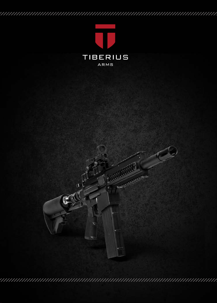
MAGAZINE & HOPPER-FED PAINTBALL RIFLE
T4.1
TIBERIUS ARMS TECHNICAL MANUAL
Page 2

Page 3

TECHNICAL MANUAL
MAGAZINE & HOPPER-FED PAINTBALL RIFLE
T4.1
Page 4

TABLE OF CONTENTS
Warnings .......................................................................................................................................................................................................Page 1
T4.1 Rie Diagram .....................................................................................................................................................................................Page 2
Universal Pack .............................................................................................................................................................................................Page 4
T4.1 Operational Instructions ...............................................................................................................................................................Page 5
T4.1 Cleaning and Maintenance ........................................................................................................................................................Page 13
Warranty and Repairs .............................................................................................................................................................................Page 14
Upper Receiver Assembly ....................................................................................................................................................................Page 16
Lower Receiver Assembly ....................................................................................................................................................................Page 26
Engine & Firing Bolt Assembly ...........................................................................................................................................................Page 27
Trigger Group ...........................................................................................................................................................................................Page 28
Regulator ....................................................................................................................................................................................................Page 29
CO2 Valve Housing ..................................................................................................................................................................................Page 30
Troubleshooting ......................................................................................................................................................................................Page 31
Page 5

WARNING: This is not a toy. Misuse may cause serious injury or
death. Eye protection designed specically for paintball must be worn by the user
and persons within range. Recommend 18 years or older to purchase. Persons
under 18 must have adult supervision. READ OWNER'S MANUAL BEFORE USING.
WARNING/LIABILITY STATEMENT
This marker is not a toy and is surrendered by Tiberius Arms, Inc., with the understanding that the purchaser
assumes all liability from unsafe handling or any action that constitutes a violation of any applicable laws or
regulations. Tiberius Arms, Inc. shall not be liable for personal injury, loss of property or life resulting from the use
of this product under any circumstances, including any intentional, reckless, negligent or accidental discharges.
All information contained in this manual is subject to change without notice. Tiberius Arms, Inc., reserves the
right to make changes and improvements to products without incurring any obligation to incorporate such
improvements in products previously sold.
If you, as a user, do not accept liability, Tiberius Arms, Inc., requests that you do not use a Tiberius Arms marker.
By using this Tiberius Arms marker you release Tiberius Arms, Inc., of any and all liability associated with its use.
WARNINGS
Treat every marker as if loaded. Never look down barrel of a paintball marker. Keep nger o trigger until ready
to shoot. Never point marker at anything you do not wish to shoot. Keep barrel blocking device in or on marker’s
muzzle when not shooting. Always remove paintballs and propellant source before disassembling. After removing
propellant source, point marker in safe direction and discharge until marker is degassed. Store marker unloaded
and degassed in secure place. Follow warnings listed on propellant source for handling and storage. Do not shoot
at fragile objects such as windows. Every person within range must wear eye, face and ear protection designed
specically to stop paintballs. Ensure the top face of the sear and outer rim of the ring bolt are free of oil, grease, or
contaminants. Tiberius Arms marker you release Tiberius Arms, Inc., of any and all liability associated with its use.
CONGRATULATIONS
Congratulations on your purchase of the T4.1 Tiberius Arms Marker!
This marker has been designed by Tiberius Arms with reliability, accuracy and durability in mind. When properly
handled, the T4.1 will give many years of dependable service.
Please take the time to read through this manual and become familiar with the parts, operation, maintenance, and
safety precautions before you attempt to load or re this marker.
By purchasing this marker, you assume total responsibility for its safe and lawful use. You must observe the same
safety precautions as you would with any rearm to assure the safety of not only yourself but everyone around you.
The operator should use caution at all times when maintaining and ring this marker.
Do not load or re this marker until you have completely read this manual and are familiar with its mechanical
operation and handling characteristics before use.
T4.1MANUAL 1
Page 6
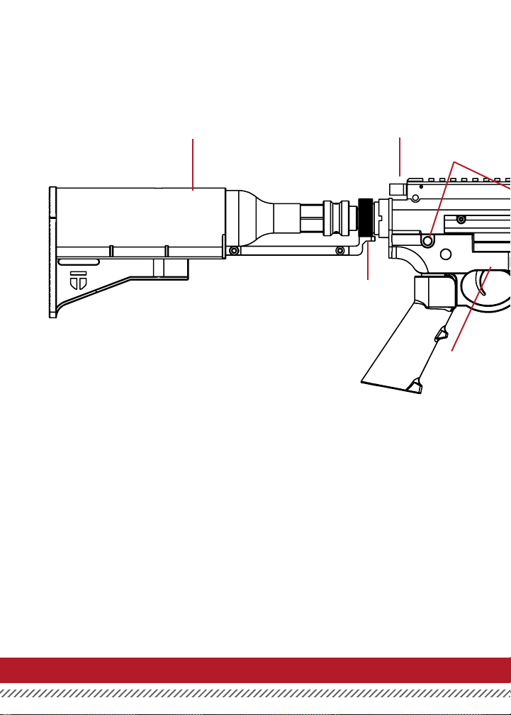
T4.1 RIFLE DIAGRAM
HPA TANK STOCK
CHARGING ROD
BOTTLE ADAPTER
CORE
CONNECTING PINS
SAFETY
T4.1MANUAL2
Page 7
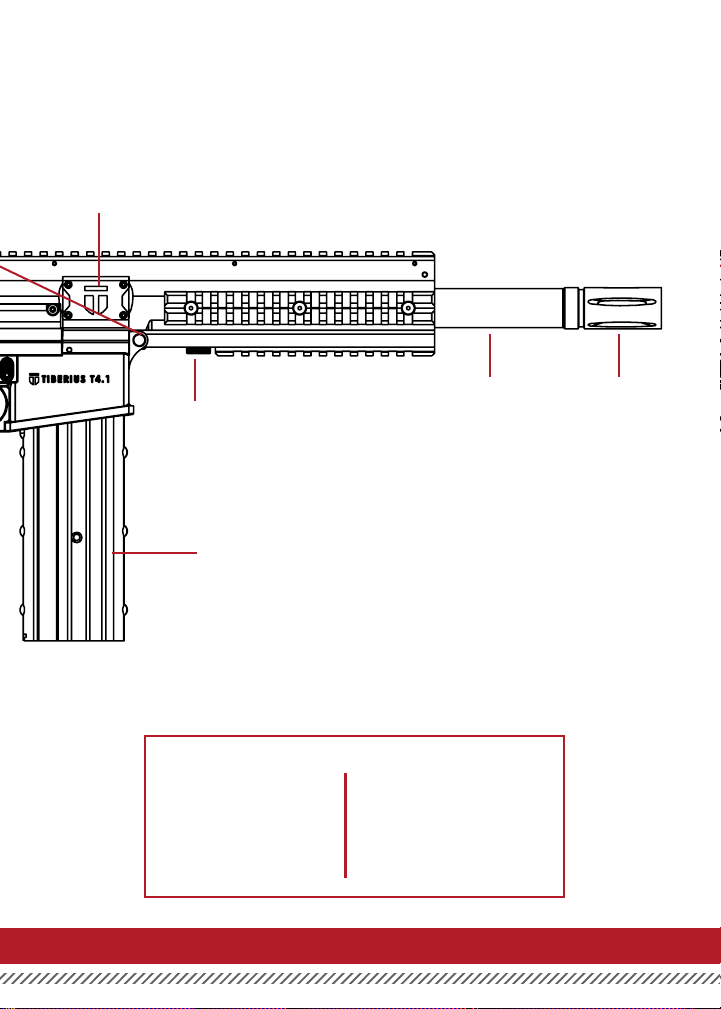
HOPPER PORT
BARREL
BARREL LOCK
MAGAZINE
MUZZLE
FLASH TIP
MODEL SPECIFICATIONS
Caliber: .68
Action: Semi-auto
Power: CO2/HPA
Length: 11 inches
Height: 8 inches
Barrel Length: 6.5 inches
Weight: 2.7 lbs.
Magazine cap.: 10
T4.1MANUAL 3
Page 8
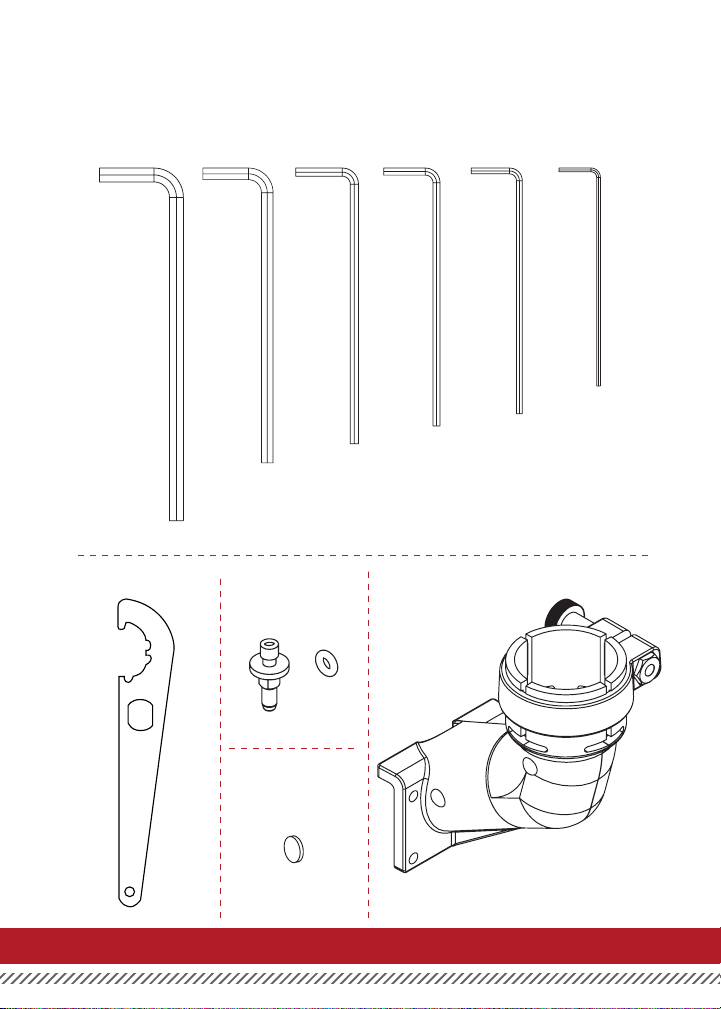
UNIVERSAL PACK
INVENTORY LIST
ALLEN WRENCHES
3/16” 4mm 7/64” 3/32” 5/64” .050”
SPANNER WRENCH
WITH O-RING
REG BODY PLUG
HOPPER ELBOWCO2 STEM
T4.1MANUAL4
Page 9
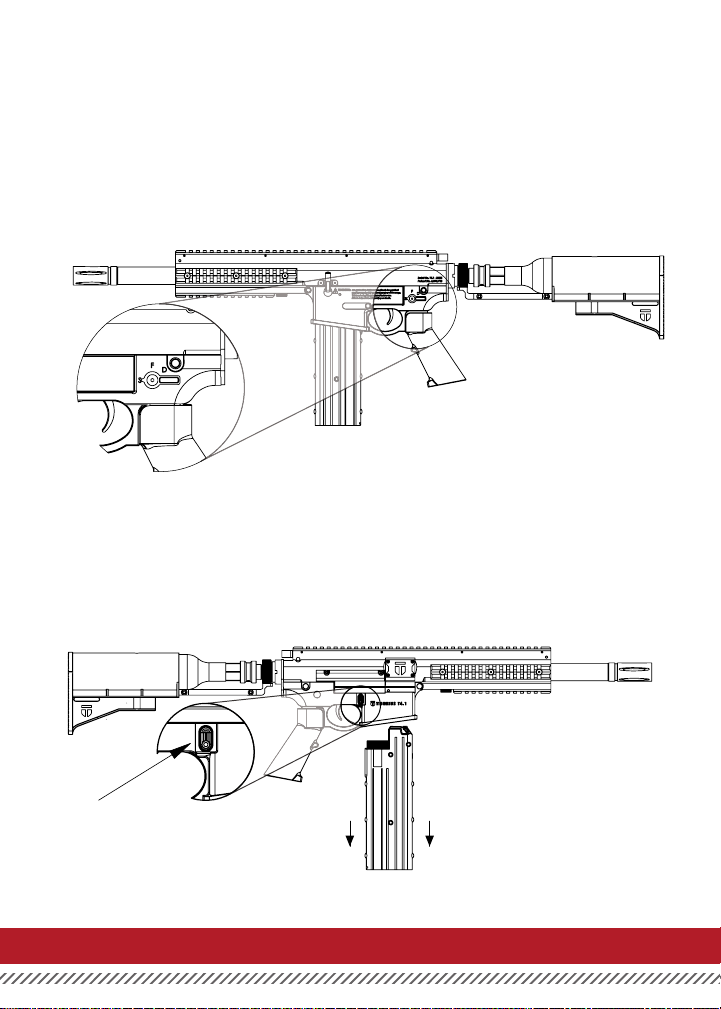
T4.1 OPERATIONAL INSTRUCTIONS
GETTING STARTED
Read this entire manual before using this marker. Keep your marker pointed in a safe direction at all times.
1. SAFETY - The safety has 3 Functions: S-Safety, F-Fire, D-Disassemble. Place the T4.1 in safe
position by aligning the safety switch with the “S”. The safety can be found on the left side of the
gun just above the grip.
CAUTION: The maker can still be red in Disassemble mode.
2. REMOVING MAGAZINE - Place your hand under the magazine, press the magazine release, and pull the
magazine free from the T4.1.
T4.1MANUAL 5
Page 10
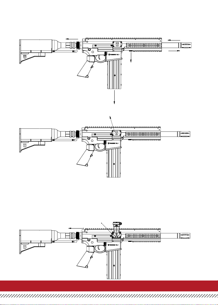
3. REMOVING THE BARREL - (1) Shut o the slide check attached to the tank. (2) Next, remove the magazine
from the marker. (3) Slightly push in the barrel and rotate the barrel lock counterclockwise. Then pull down
the barrel lock. (4) Your barrel is now free to slide out along the barrel lock track.
1
3
3
2
4
HOPPER ATTACHMENT
1. REMOVE HOPPER COVER PLATE - Remove the Hopper Cover Plate by removing the four (4) Cover Plate
Screws, (Top two screws H-S 440 3/4, Bottom two screws H-S 440 3/8) by using a 3/32 Allen Wrench.
2. ROTATE BARREL - To rotate the barrel pull back on the charging handle located on the rear of the gun
above the stock until it locks in the rear position. Leave in this position to shoot using a hopper
3. BARREL RELEASE - Press the release button located on the left side of the marker to switch back to
magazine mode.
4. ATTACH HOPPER ELBOW - Attach the Hopper Elbow located in the universal pack that came with the
rie using the four (4) Hopper Screws, also located in the universal pack. These screws require a 3/32 Allen
Wrench.
T4.1MANUAL6
Page 11
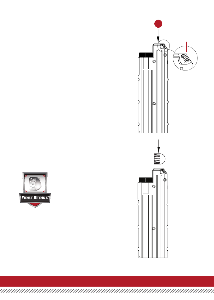
LOADING PAINT
Place 10 projectiles into the magazine from the top. The
projectiles will be held in place automatically by the
projectile retainer pin.
PROJECTILE
RETAINER PIN
FIRST STRIKE
®
LOADING FIRST STRIKE
Always load First Strike projectiles so rounded
nose exits barrel rst. Always chronograph
with First Strike before use to ensure velocity
is below 300 fps.
T4.1MANUAL 7
Page 12
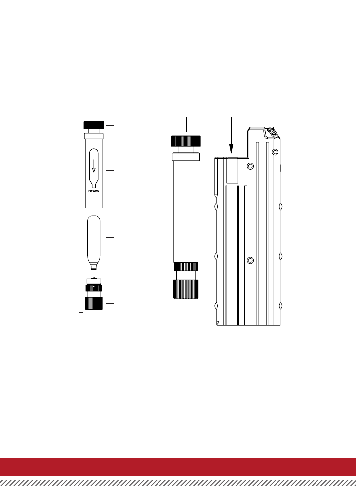
CHARGING THE MAGAZINE
To charge the canister remove it from the magazine. Then remove the magazine plug assembly from the canister.
Insert a 12g cartridge as depicted on the canister. Then with the punctured knob screwed out as far as it can be in
the magazine plug, attach the magazine plug to the canister.. Finally, tighten the Puncture Nob until the cartridge
is punctured.
T4.1 Mag Valve
Assembly
Canister
12g cartridge
Magazine
plug assembly
Magazine plug
Puncture Knob
T4.1MANUAL8
Page 13
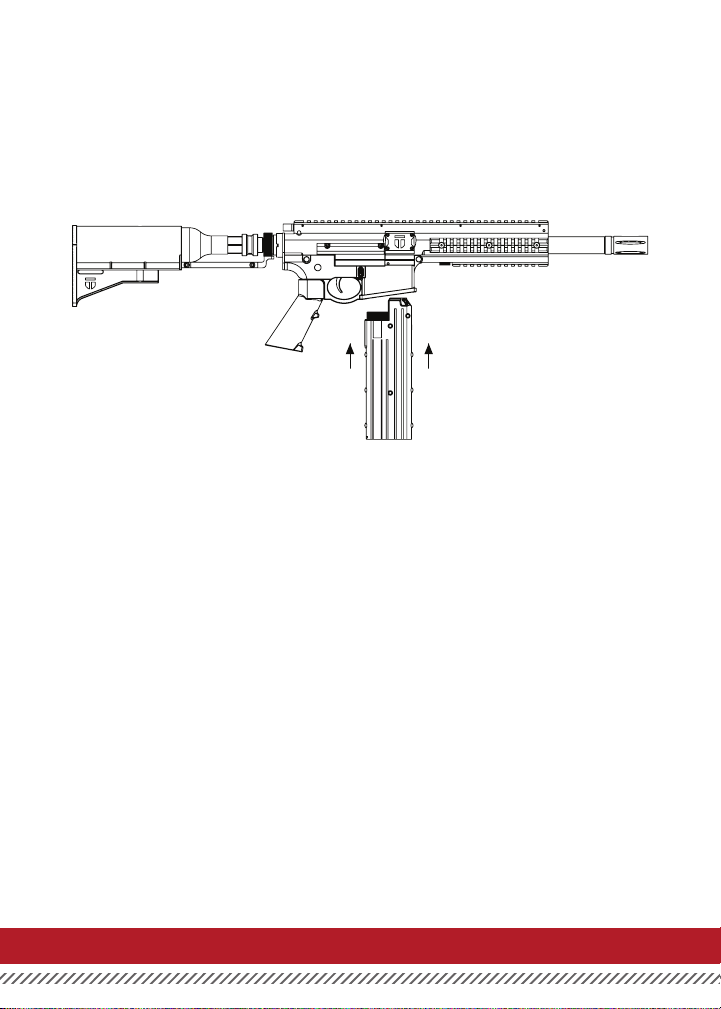
LOADING MAGAZINE
Place the magazine into the magazine cavity in the lower receiver. Once the mag has started into the cavity, seat it
completely until has been secured by the magazine release.
T4.1MANUAL 9
Page 14
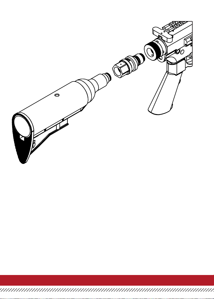
INSTALLING THE BOTTLE
1. Attach the bottle to the on/o ASA leaving the adapter in the o position.
2. Next, screw the ASA into the bottle adapter.
3. To air up the marker, switch the ASA to the ON position.
T4.1MANUAL10
Page 15

FIRING THE T4.1
1. If the CO2 cartridge has been punc tured by the puncture pin and the magazine has been inserted into the
gun, then the T4.1 is now ready to re. Point the T4.1 in a safe direction, rotate the safety switch so that it is
aligned with the “F”, and pull the trigger.
NOTE - extra magazines can be carried for quick reloads in the eld.
UNLOADING THE T4.1
1. Place T4.1 in the safe mode and point in a safe direction. If all projectiles have been red, place hand under
magazine and press magazine release with other hand. Catch magazine so it does not fall on ground.
Visually inspect the magazine well to ensure all projectiles are clear from the T4.1. Visually inspect the
projectile view port to ensure all projectiles are clear.
2. If all projectiles have not been red, follow above procedures but ensure that you turn the T4.1 on its side
while removing the magazine. The projectile that is in the chamber will be free and can fall on the ground
if the T4.1 is kept in a vertical position. Place your hand under the magazine well and capture the loose
projectile as you turn the T4.1 vertically.
3. Pull back on the projectile retainer pin to remove the projectiles from the magazine and turn the ip knob
base screw counterclockwise to free the CO2 cartridge from the magazine.
4. Your T4.1 should now be free of any projectiles. Verify the T4.1 is on safe and store in a safe and secure
location.
SET VELOCITY
1. Inser t a 3/16” Allen Wrench as depicted.
2. To increase velocity, tum clockwise. To decrease velocity
turn counter-clockwise.
3. Fire once to clear chamber after each adjustment,
then measure velocity of the second shot.
SAFETY TIP: Always measure marker’s velocity before
playing paintball. Never shoot at velocities in excess
of 300 ft/s (91 .44 mls). Recommended velocity is 270 ft/s.
T4.1MANUAL 11
Page 16
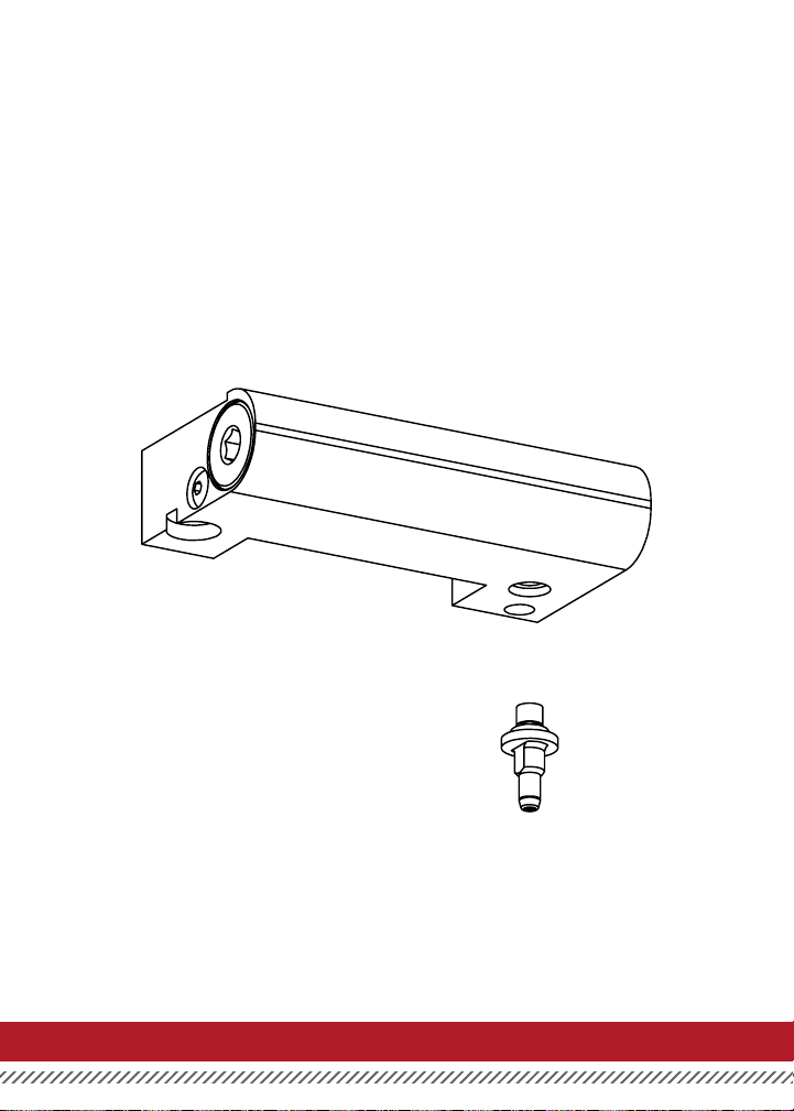
CO2 STEM INSTALLATION
SOLID CO2 STEM INSTALLATION
1. To replace the Solid CO2 Stem with the CO2
Stem, rst remove the lower receiver from
the upper receiver.
2. The CO2 Stem can be removed with a 4mm
wrench or a small adjustable wrench. Be
sure that O-Ring is on the Solid CO2 Stem.
DO NOT OVER TIGHTEN onto the Reg.
T4.1MANUAL12
Page 17

T4.1 CLEANING & MAINTENANCE
CLEANING
Never perform maintenance on a loaded or pressurized T4.1 marker.
Remove all projectiles and CO2 cartridges from the magazine and marker prior to doing any
cleaning or maintenance.
Never use petroleum based cleaning solvents or lubricants.
Do not use cleaning solvents that come in aerosol cans.
To clean the T4.1 marker, remove the barrel as described in the “Operational Instructions”.
Use a .68 caliber soft nylon brush or 12 gauge patch tip with a soft cotton cloth to clean the barrel.
Do not place lubricant or water in the barrel of the T4.1. It is designed to be used with the barrel completely dry.
Keep the barrel of the T4.1 dry.
Wipe o any dirt or grime from the outside of the T4.1 with a dry cloth.
OILING THE MARKER
IMPORTANT: Before performing any of the following instructions, remove magazine. Point marker
in safe direction and discharge until degassed.
For optimum performance, do the following monthly:
1. Place one drop of oil between trigger release and trigger rotator.
(See Page 28)
2. Remove the regulator spring pad (See page 29) and oil the regulator
spring pad O-Ring.
3. Remove the engine assembly (See page 17) and lightly grease the
AC Cap O-Ring.
4. Place one drop of oil on CO2 O-Ring found at top of CO2 Valve
and Magazine (See page 21).
OPERATIONAL CONSIDERATIONS
If the CO2 cartridge is punctured in a magazine, it should be replaced if the T4.1 is not used for 24 hours.
The operational temperature range for the T4.1 marker is 37° F to 120°F.
T4.1MANUAL 13
Page 18

WARRANTY AND REPAIRS
Tiberius Arms Inc is dedicated to providing you with the quality support necessary for the utmost satisfaction
of that technology. Tiberius Arms products are crafted with the nest materials and designed for trouble-free
performance. We warrant that this marker is found free from defects in materials and workmanship for a period of
1 year from the original date of purchase. Unauthorized modications alterations, neglect, or abuse of this product
voids any warranty. The warranty covers the parts and labor required to repair the product to proper working order.
To register your marker for warranty please ll out the included warranty card or register online at
www.tiberiusarms.com
In the event warranty or other non-warranty related repairs are required, send the product(s) to Tiberius Arms Inc.
We strive to complete the necessary repair work within a reasonable amount of time and return it to you via the
best shipping method. On claims submitted as outlined, Tiberius Arms Inc. will repair or replace, free of charge, any
of its markers that have failed through defect in material or workmanship. For assistance with warranty and repair,
call 260-478-2500.
For warranty and non-warranty repair, ship the product(s) to Tiberius Arms Inc. with postage or delivery charges
prepaid. Include a brief statement regarding the requested repair, point of contact, return address, and telephone
number where the point of contact may be reached during normal business hours. Ship to:
Tiberius Arms Inc.
ATTN: Warranty
2717 Ferguson Road
Ft. Wayne, IN. 46809
Note: Always unload and remove CO2 or HPA bottles before shipping a marker.
T4.1MANUAL14
Page 19

T4.1MANUAL 15
Page 20
1
2
3
5
6
8
7
T4.1MANUAL16
Page 21
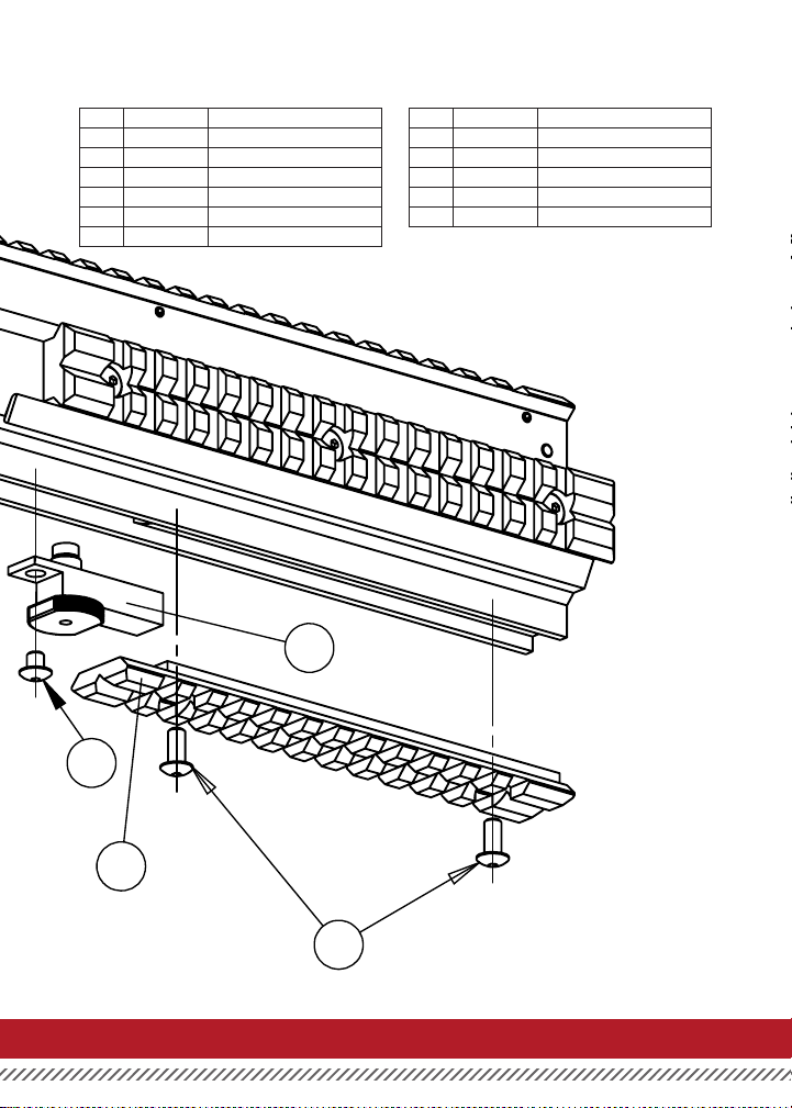
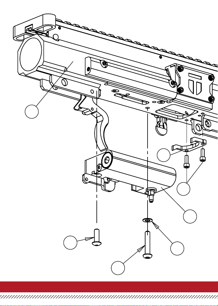
UPPER RECEIVER ASSEMBLY
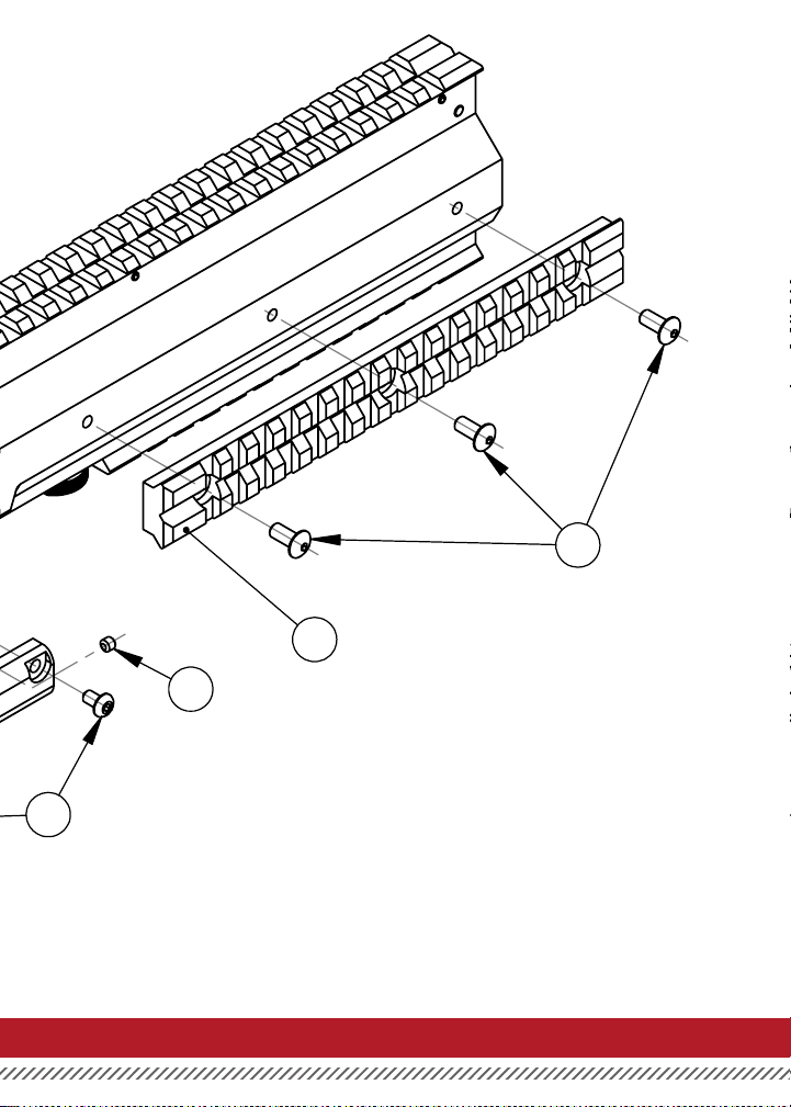
ITEM NO. PART NUMBER NAME
1 42-2046 Upper Receiver
2 T4-2943 Release Fork - T4
3 H-S 440 5/16 Release Fork Screws
4 P4-1940 Barrel Catch Assembly
5 41-2540 Assembled Regulator
6 H-B 832 1/2 Regulator Rear Screw - T4
4
ITEM NO. PART NUMBER NAME
7 H-B 832 7/8 Reg Body Screw
8 H-WSHR 8 T Reg Bod Tooth Washer
9 T4-1847 Lower Tac Rail
10 H-B 832 5/16 Tac Rail Screw
11 H-B 832 1/4 Barrel Catch/Lock Screw
11
9
10
T4.1MANUAL 17
Page 22
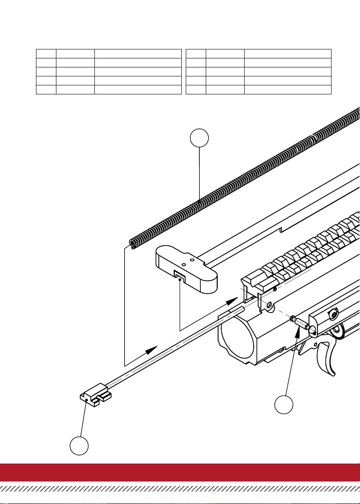
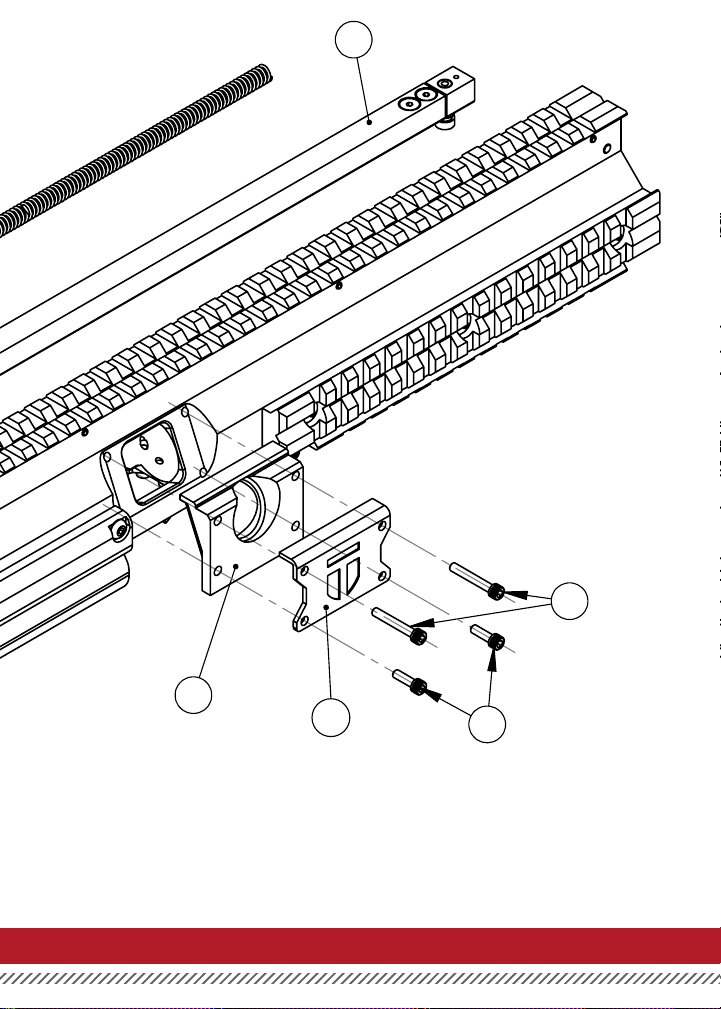
UPPER RECEIVER ASSEMBLY
ITEM NO. PART NUMBER NAME
1 SPRG49 Charging Handle Spring
2 T4-1745 Stop Block
3 T4-1746 Stop Block Pin
4 T4-1946 Hopper Converter
ITEM NO. PART NUMBER NAME
5 H-S 440 3/4 Hopper Converter Screw
6 T4-1740 Charging Handle Assembly
7 H-S 440 3/8 Lower Hopper Converter Screw
8 MR-1973 Hopper Cover Plate
1
3
2
T4.1MANUAL18
Page 23
6
5
4
8
7
T4.1MANUAL 19
Page 24
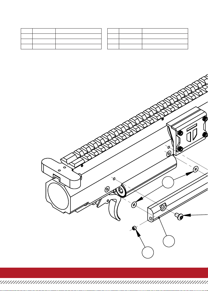
4
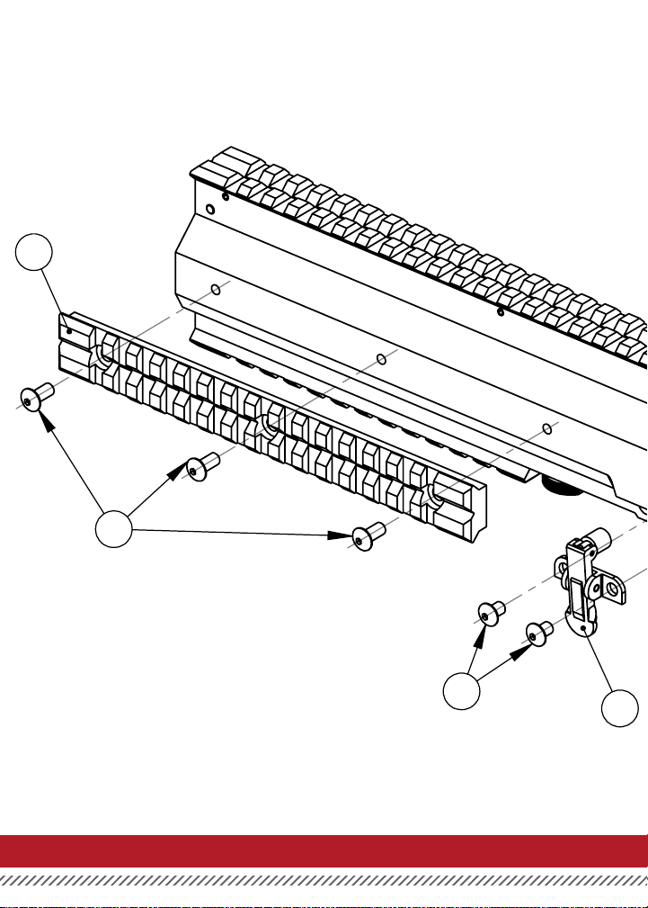
UPPER RECEIVER ASSEMBLY
ITEM NO. PART NUMBER NAME
1 ORNG 006-B90 Reg Sealing O-Ring
2 H-SSS 632 1/8 Alternate Air Sealing Screw
3 42-2041 Alternate Air Attachment
ITEM NO. PART NUMBER NAME
4 H-B 632 3/8 Alternate Air Screw
5 T4-1848 Side Tac Rail
6 H-B 832 5/16 Tac Rail Screw
1
3
2
T4.1MANUAL20
Page 25
6
5
2
4
T4.1MANUAL 21
Page 26
1
2
3
4
T4.1MANUAL22
Page 27
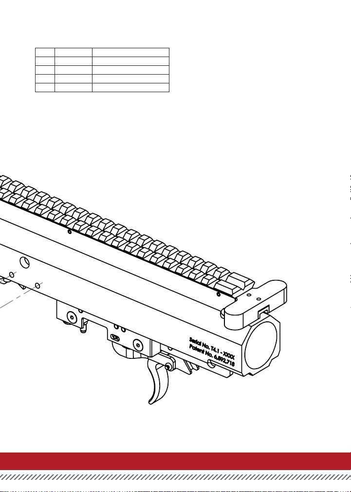
UPPER RECEIVER ASSEMBLY
ITEM NO. PART NUMBER NAME
1 T4-1848 Side Tac Rail
2 H-B 832 5/16 Tac Rail Screw
3 H-B 832 1/4 Barrel Catch Screws
4 T4-1940 Barrel Catch Assembly
T4.1MANUAL 23
Page 28
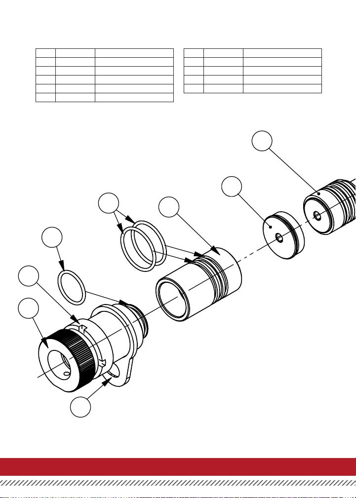
UPPER RECEIVER ASSEMBLY
ITEM NO. PART NUMBER NAME
1 ORNG 018-P70 Bottle Adapter O-RIng
2 AC-4057 Stock Ring
3 42-2143 Bottle Adapter
4 42-2141 Bottle Adapter Core
5 ORNG 022-B70 Adapter Core O-Ring
ITEM NO. PART NUMBER NAME
6 AC 4056 Stock Plate
7 41-2100 T4.1 Engine
8 81-2105 Gun Body Cap
9 41-2240 T4.1 Firing Bolt
7
8
5
4
1
2
3
6
T4.1MANUAL24
Page 29
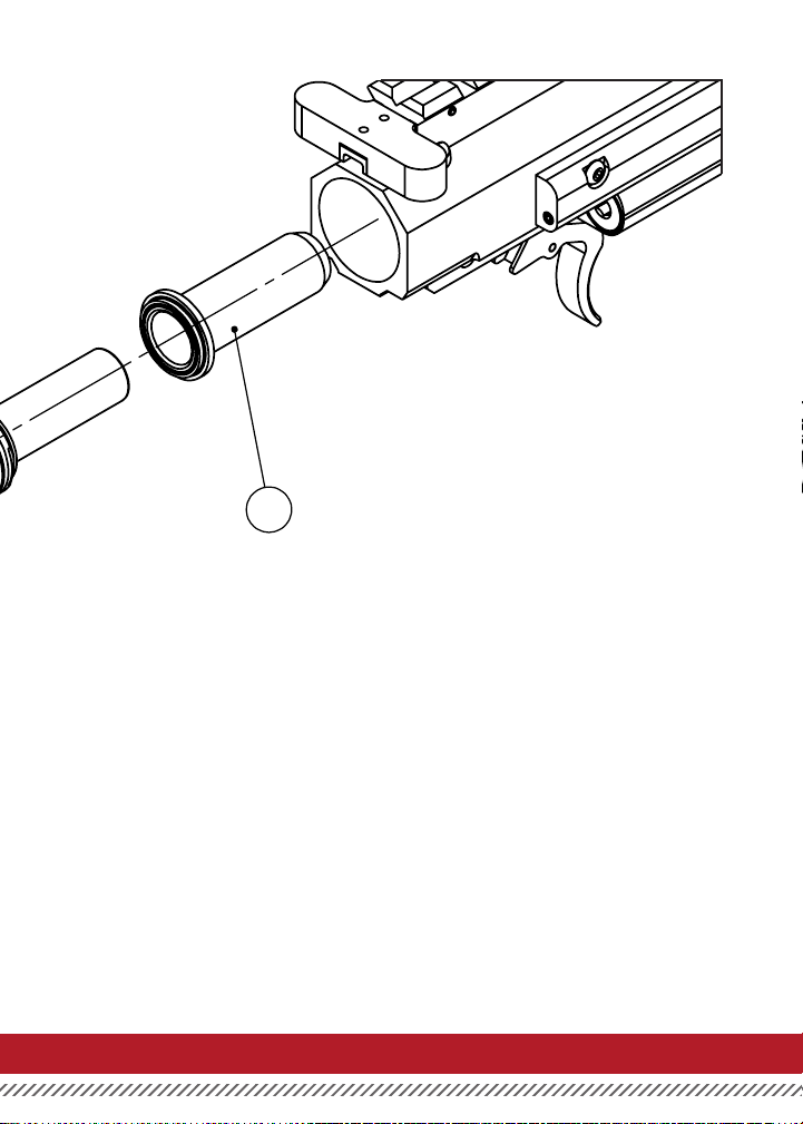
9
T4.1MANUAL 25
Page 30
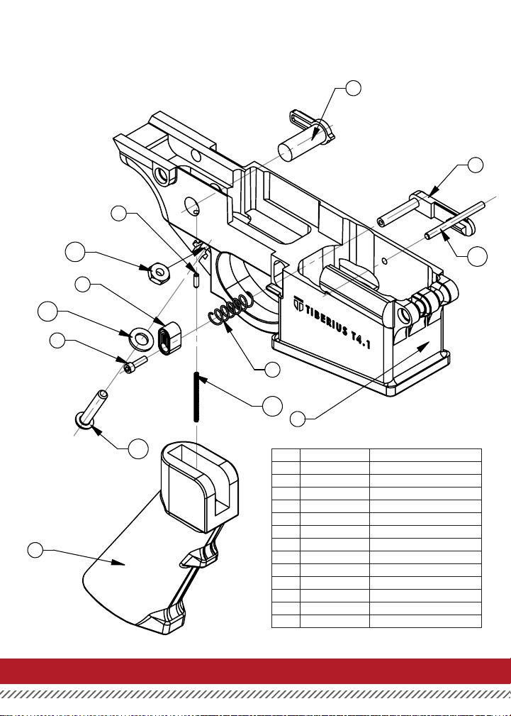
LOWER RECEIVER ASSEMBLY
5
4
3
13
12
2
11
6
7
9
1
10
8
ITEM NO. PART NUMBER NAME
1 42-1541 Lower Receiver
2 T4-1441 Mag Catch Button
3 T4-1443 Mag Catch
4 T4-1642 Safety Switch
5 T4-1044 Brass Detents
6 SHCS 440 5/16 Mag Catch Screw
7 SPRG 41 Mag Catch Spring
8 T4-4041 Handle
9 SPRG 46.2 Detents Spring-Safety
10 BHCS 10-24 x1 Handle Screw
11 WSHR 10-808 Handle Lock Washer
12 DOWL 1/8 x_1 1/2 Mag Guide Pen
13 NUT 10-24 Handle Nut
T4.1MANUAL26
Page 31
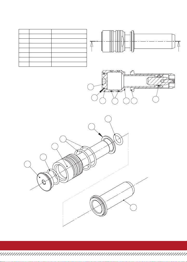
ENGINE & FIRING BOLT ASSEMBLY
1
6
2
7
3
5
1
8
2
9
3
5
6
4
7
B
A
8
7
6
5
ITEM NO. PART NUMBER NAME
1 81-2101 Air Chamber Plug
2 81-2104 Air Chamber
3 45-2107 AC Shock Absorber
4 ORNG 110-P70 AC Cap O-Ring
5 41-2240 T4.1 Firing Bolt
6 ORNG 019-B70 AC Plug O-Ring
7 ORNG 020-B70 AC OD O-Ring
Note: Do not attempt to disassemble bolt and ring
pin (Item 5). The alignment is set by factory xtures
and cannot be reassembled outside the factory.
1
6
2
7
5
3
4
4
3
7
2
6
1
5
T4.1MANUAL 27
Page 32
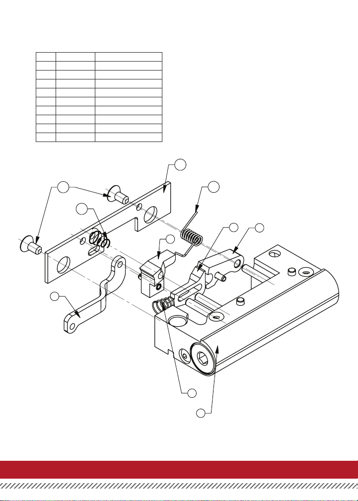
TRIGGER GROUP
ITEM NO. PART NUMBER NAME
1 41-2541 Regulator Body-T4
2 H-F 832 3/8 Trigger Cover Screw
3 45-2402 Sear
4 45-2401 Trigger Cover Plate
5 45-2405 Release
6 SPRG10 Release/Rotator Spring
7 45-2404 Rotator
8 SPRG02 Sear Spring
9 T4-2448 T4 Linkage
4
2
8
6
5
3
7
9
6
1
T4.1MANUAL28
Page 33
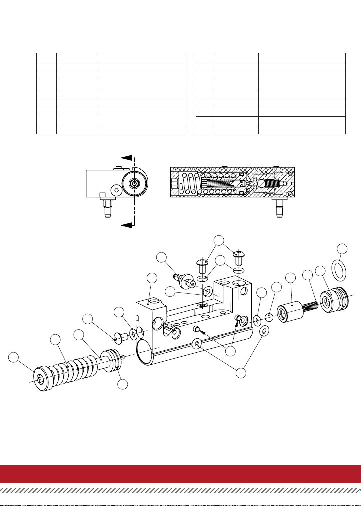
REGULATOR
ITEM NO. PART NUMBER NAME
1 41-2541 Regulator Body-T4
2 81-2502 Regulator Spring Pad Complete
3 81-2505 Regulator End Screw
4 45-2506 Regulator Adjuster
5 81-2507 CO2 Stem
6 45-2508 Reg Valve Sleeve
7 BHCS 6-32x3/16 Regulator Sealing Screws
8 ORNG 006-B90 Reg Sealing/Reg Body O-Ring
A
A
5
1
ITEM NO. PART NUMBER NAME
9 ORNG 006-B90 Reg Sealing/Reg Body O-Ring
10 ORNG 006-P90 Regulator Valve O-Ring
11 ORNG 012-P70 Regulator Spring Pad O-Ring
12 ORNG 012-B70 Regulator End Screw O-Ring
13 ORNG 006-B70 CO2 Stem O-Ring
14 SPRG13 Regulator Valve Spring
15 SPRG 05 Regulator Spring
16 H-BALL 316 Regulator Valve Ball
13
7
8
14
6
16
10
12
3
7
2
15
4
8
17
9
11
NOTE
O-Ring #10 is the same size and color as O-Ring #6 on Page 30.
This O-Ring is harder than the O-Ring on Page 30.
Relief valve is preset at the factory and is not user serviceable.
Consult factory or authorized service center for assistance.
T4.1MANUAL 29
Page 34
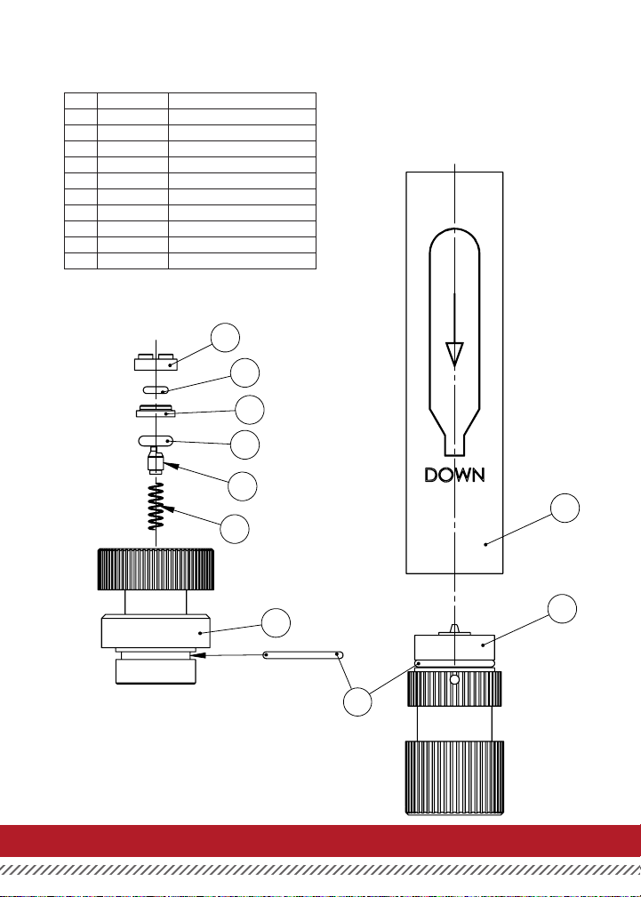
C02 VALVE HOUSING
ITEM NO. PART NUMBER NAME
1 41-3241 Valve Housing
2 ORNG 017-P70 Valve Housing Sealing O-RIng
3 SPRG 03 C02 Valve Spring
4 81-3203 CO2 Drum Valve
5 81-3213 Valve Spacer
6 ORNG 006-P70 C02 Valve Spacer O-Ring
7 81-3214 C02 Cap
8 41-3248.0 CO2 Canister (Sing)
9 ORNG 105-P90 C02 Valve Body O-Ring
10 41-3250 C02 Plug Assembly
7
6
5
9
4
3
NOTE
O-Ring #6 is the same size and color as O-Ring #10 on Page
29. This O-Ring is softer than the O-Ring on Page 29.
8
1
10
2
T4.1MANUAL30
Page 35

TROUBLESHOOTING
PAINT BREAKAGE
If you experience more than a small number of broken paintballs, then there are 4 things to check:
1. First, be sure that the marker is free of broken paintballs and other debris.
2. Second, make sure that the barrel is locked in its correct position, and that both detents are installed so that
they catch a projectile as it enters the breach.
3. Third, make sure that the red First StrikeTM spring is not installed in the magazine (See page 10)
4. Fourth, make sure the maker is set to a reasonable velocity (never over 300 ft. per sec.)
MAGAZINE
If your magazine is leaking CO2, it is coming from one of three seals:
Valve Housing Seal (#2 - Page 30) - CO2 leaks out the top or bottom of the canister
CO2 Valve Spacer O-Ring (#6 - Page 30) - CO2 leaks when the magazine is inserted in marker
Housing O-Ring (#9 - Page 30) - CO2 leaks from the top of the magazine while the magazine isn’t inside the gun.
If the magazine is leaking slightly from this area, try inserting and ejecting into the maker 2-3 times. This may seat
the valve and eliminate the leak.
BOLT PUSH
When re-assembling the marker be sure to push the bolt forward before installing the regulator.
(See note on page 27.) To push the bolt the barrel and bolt spring must be removed from the marker.
T4.1MANUAL 31
Page 36

888.982.2842 | 2717 FERGUSON ROAD | FORT WAYNE, INDIANA 46809
 Loading...