

TIBCO LogLogic LX 4020, LogLogic ST, LogLogic ST 1020, LogLogic ST 2020-SAN, LogLogic ST 4020 Hardware Installation Manual
...
TIBCO LogLogic
®
Log Management Intelligence (LMI)
Hardware Installation Guide
Software Release: 5.3.1
August 2012

Important Information
SOME TIBCO SOFTWARE EMBEDS OR BUNDLES OTHER TIBCO SOFTWARE. USE OF SUCH EMBEDDED OR
BUNDLED TIBCO SOFTWARE IS SOLELY TO ENABLE THE FUNCTIONALITY (OR PROVIDE LIMITED ADD-ON
FUNCTIONALITY) OF THE LICENSED TIBCO SOFTWARE. THE EMBEDDED OR BUNDLED SOFTWARE IS NOT
LICENSED TO BE USED OR ACCESSED BY ANY OTHER TIBCO SOFTWARE OR FOR ANY OTHER PURPOSE.
USE OF TIBCO SOFTWARE AND THIS DOCUMENT IS SUBJECT TO THE TERMS AND CONDITIONS OF A
LICENSE AGREEMENT FOUND IN EITHER A SEPARATELY EXECUTED SOFTWARE LICENSE AGREEMENT,
OR, IF THERE IS NO SUCH SEPARATE AGREEMENT, THE CLICKWRAP END USER LICENSE AGREEMENT
WHICH IS DISPLAYED DURING DOWNLOAD OR INSTALLATION OF THE SOFTWARE (AND WHICH IS
DUPLICATED IN THE LICENSE FILE) OR IF THERE IS NO SUCH SOFTWARE LICENSE AGREEMENT OR
CLICKWRAP END USER LICENSE AGREEMENT, THE LICENSE(S) LOCATED IN THE “LICENSE” FILE(S) OF
THE SOFTWARE. USE OF THIS DOCUMENT IS SUBJECT TO THOSE TERMS AND CONDITIONS, AND YOUR
USE HEREOF SHALL CONSTITUTE ACCEPTANCE OF AND AN AGREEMENT TO BE BOUND BY THE SAME.
This document contains confidential information that is subject to U.S. and international copyright laws and treaties.
No part of this document may be reproduced in any form without the written authorization of TIBCO Software Inc.
TIBCO and LogLogic are either registered trademarks or trademarks of TIBCO Software Inc. and/or subsidiaries of
TIBCO Software Inc. in the United States and/or other countries.
All other product and company names and marks mentioned in this document are the property of their respective
owners and are mentioned for identification purposes only.
THIS SOFTWARE MAY BE AVAILABLE ON MULTIPLE OPERATING SYSTEMS. HOWEVER, NOT ALL
OPERATING SYSTEM PLATFORMS FOR A SPECIFIC SOFTWARE VERSION ARE RELEASED AT THE SAME
TIME. PLEASE SEE THE README.TXT FILE FOR THE AVAILABILITY OF THIS SOFTWARE VERSION ON A
SPECIFIC OPERATING SYSTEM PLATFORM.
THIS DOCUMENT IS PROVIDED “AS IS” WITHOUT WARRANTY OF ANY KIND, EITHER EXPRESS OR IMPLIED,
INCLUDING, BUT NOT LIMITED TO, THE IMPLIED WARRANTIES OF MERCHANTABILITY, FITNESS FOR A
PARTICULAR PURPOSE, OR NON-INFRINGEMENT. THIS DOCUMENT COULD INCLUDE TECHNICAL
INACCURACIES OR TYPOGRAPHICAL ERRORS. CHANGES ARE PERIODICALLY ADDED TO THE
INFORMATION HEREIN; THESE CHANGES WILL BE INCORPORATED IN NEW EDITIONS OF THIS DOCUMENT.
TIBCO SOFTWARE INC. MAY MAKE IMPROVEMENTS AND/OR CHANGES IN THE PRODUCT(S) AND/OR THE
PROGRAM(S) DESCRIBED IN THIS DOCUMENT AT ANY TIME.
THE CONTENTS OF THIS DOCUMENT MAY BE MODIFIED AND/OR QUALIFIED, DIRECTLY OR INDIRECTLY, BY
OTHER DOCUMENTATION WHICH ACCOMPANIES THIS SOFTWARE, INCLUDING BUT NOT LIMITED TO ANY
RELEASE NOTES AND "READ ME" FILES.
Copyright © 2002- 2012 TIBCO Software Inc. ALL RIGHTS RESERVED.
TIBCO Software Inc. Confidential Information
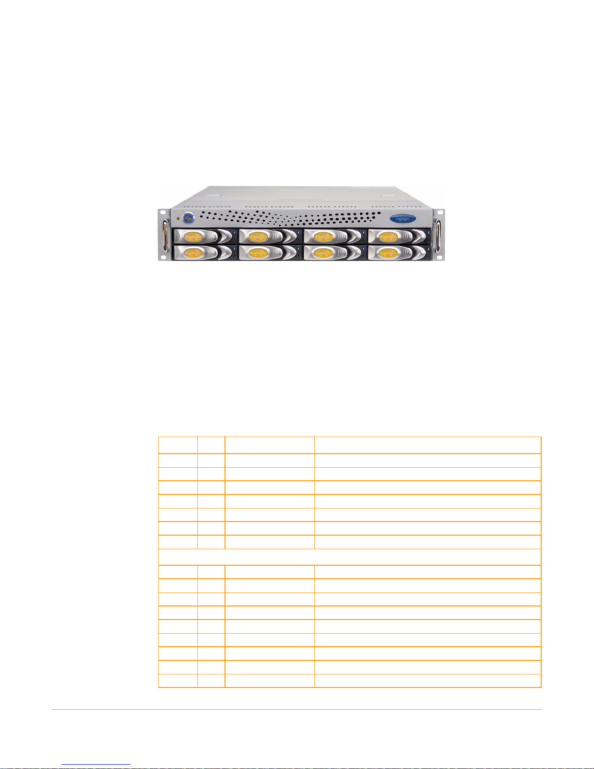
Congratulations on purchasing a LogLogic Appliance!
The LogLogic® Appliance-based solution enables you to capture and manage log data
from all types of sources in your enterprise. LogLogic Appliances install within minutes
and begin collecting and aggregating data from connected log sources immediately.
Follow these steps to quickly install your LogLogic Appliance. For logging in and
configuring your Appliance refer to the LogLogic Installation and Upgrade Guide.
Step 1: Unpack and Verify Parts in the Kit
Unpack and verify the following parts are available in the kit.
Table 1 Appliance Kit Components
Item Qty Part Number Description
1. 1 N/A LogLogic Appliance
2. 2 403-0002-00 Power cords (Note: LX820 Appliance has only 1 power cord)
3. 1 706-0063-00 Rail Kit
4. 1 403-0014-00 Null modem cable, DB9 F/F, 6 feet
5. 1 100-0712-01 Documentation & Supplemental CD
6. 1 100-0725-01 Pre-ship FQC Checklist
7. 1 100-0736-01 Packing list
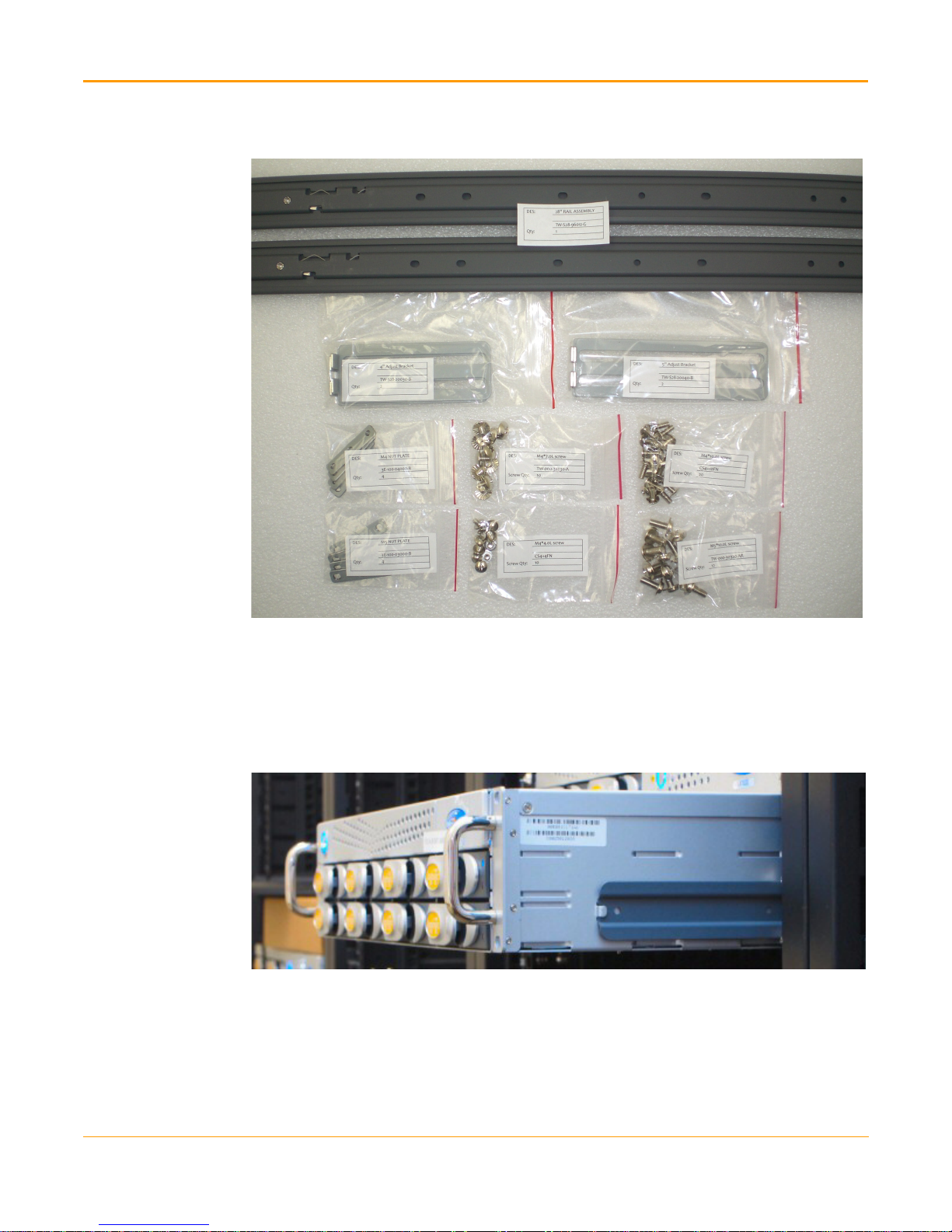
Rail Kit Components
1. 1 TW1-S28-96012-G
2. 2 TW1-S28-20030-B
3. 2 TW1-S28-20040-B
4. 4 3E-100-03000-B
5. 4 3E-100-04000-B
6. 12 TW-000-30320-AR
7. 20 CS4+10FN
8. 10 CS4+4FN
9. 10 TW-000-30230-A
28” RAIL
4” Adjust Bracket
5” Adjust Bracket
M5 Nut Plate
M4 Nut Plate
M5 x 10.0L screws
M4 x 10.0L screws
M4 x 4.0L screws
M5 x 10.0L screws
1
Step 2: Attach Mounting Rail Brackets
Figure 1 Rail Kit Components
Step 2: Attach Mounting Rail Brackets
The position of chassis and rails with a side view of cabinet with one-2U system is shown
below.
Figure 2 Side View of the Appliance
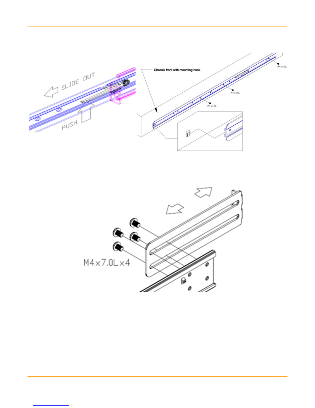
1. Remove the two identical main rails and the inner rails from the box.
2. Attach inner rails to chassis (either left or right side) by using M4x4.0L screws. Use 4
screws for 1U and 3 screws for 2U on each side.
2
Step 2: Attach Mounting Rail Brackets
Figure 3 Attach Inner Rails
3. For Cabinet with square mounting holes: Attach and screw in the adjustable rear
bracket to the outer rail as shown below (the rear bracket should be movable in front
and back).
Figure 4 Attach Rear Bracket
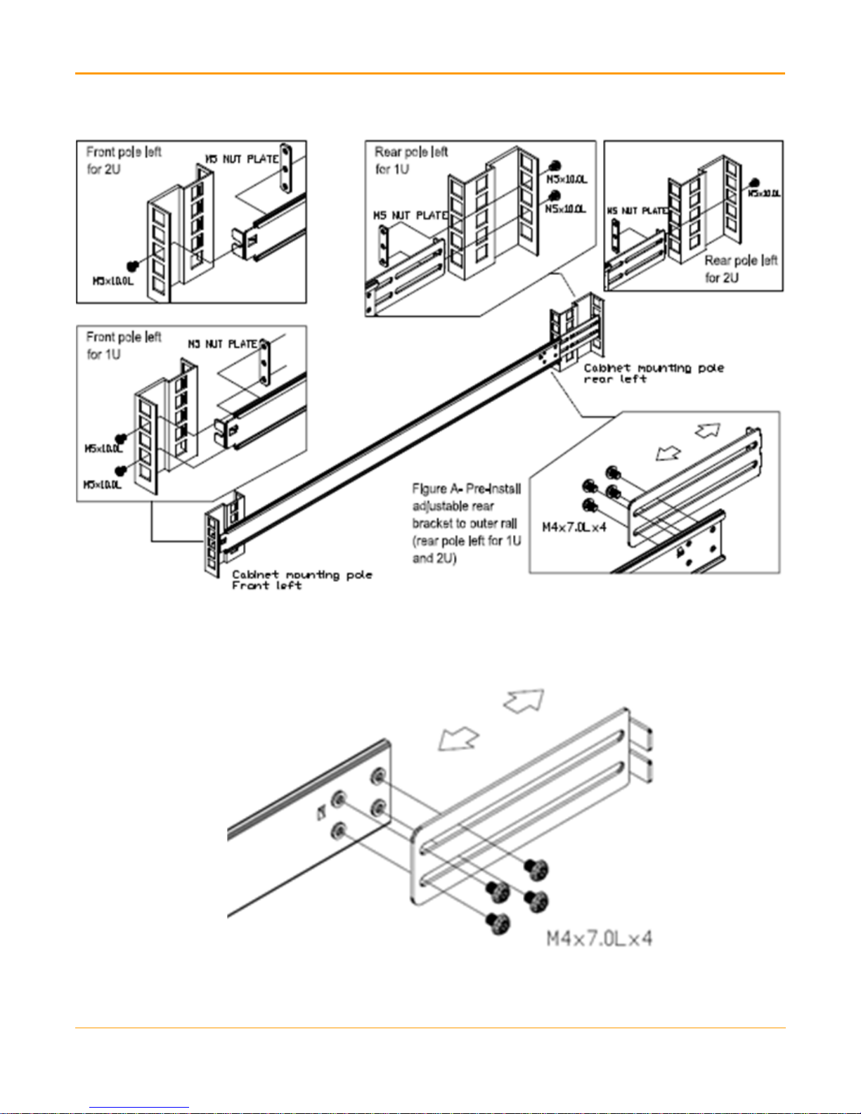
4. Follow the orientation specified below to install the outer rail and rear bracket with
screws and nut plates on the cabinet. Tighten the screws (as show in Figure 4) after the
whole outer rail set is mounted to the cabinet posts.
3
Step 2: Attach Mounting Rail Brackets
Figure 5 Install Outer Rails
5. For Cabinet with round mounting holes: Attach and screw in the adjustable rear
bracket to the outer rail as shown below (the rear bracket should be movable in front
and back).
Figure 6 Attach Rear Bracket
6. Follow the orientation specified below to install the outer rail and rear bracket with
screws and nut plates on the cabinet. Tighten the screws (as show in Figure 6) after the
whole outer rail set is mounted to the cabinet posts.
4
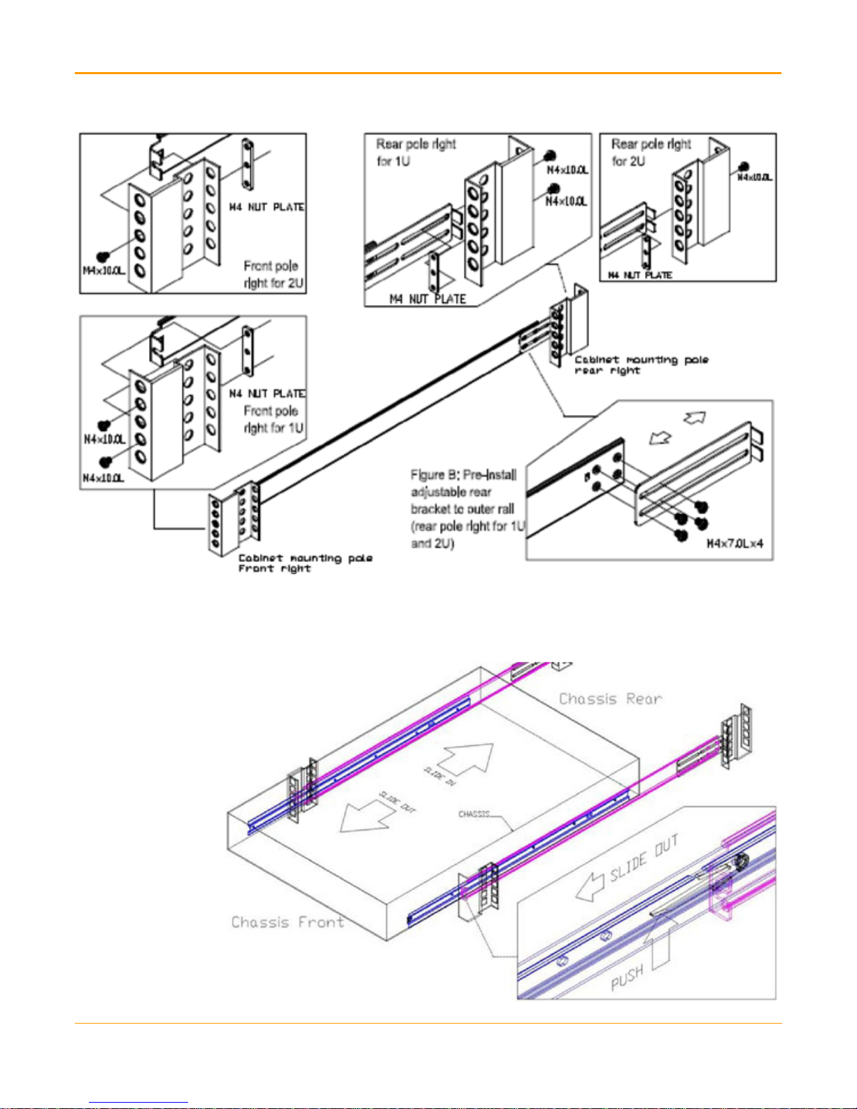
Figure 7 Install Outer Rails
Step 2: Attach Mounting Rail Brackets
7. Slide the chassis into the cabinet by inserting inner rails to the outer rail mounted in
the cabinet.
Figure 8 Slide the Chassis
5
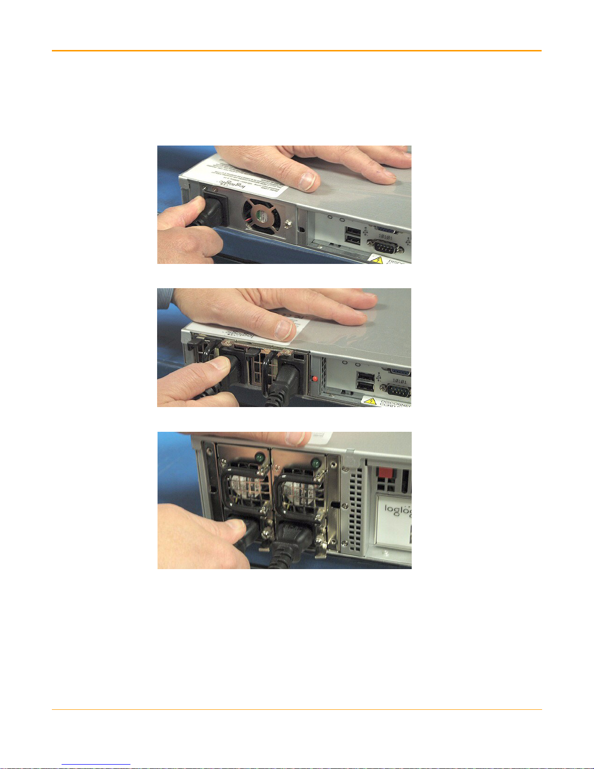
Step 3: Connect Cables
Step 3: Connect Cables
1. Connect the power cables (located at the back side of the Appliance) as shown below.
Figure 9 Connected Power Cable (LX820 - 1 Power Cable)
Figure 10 Connected Power Cables (for 1U system)
Figure 11 Connected Power Cables (for 2U system)
6
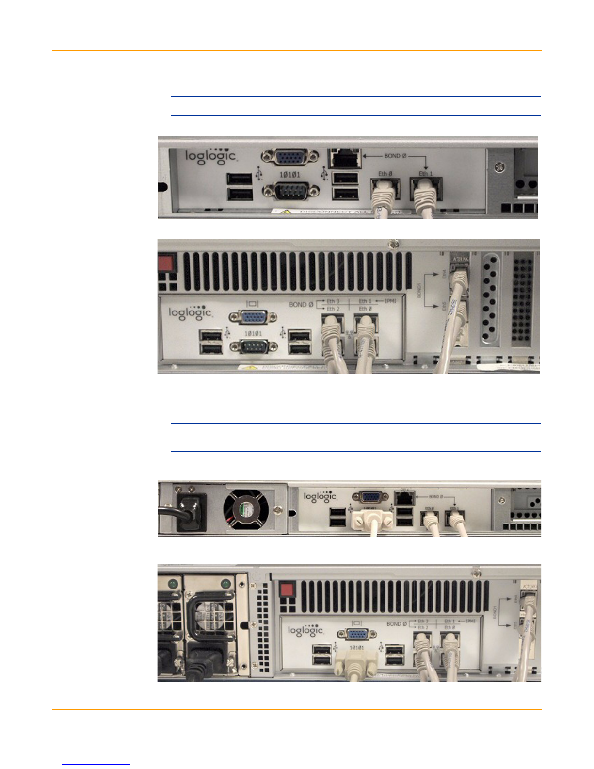
Step 3: Connect Cables
2. Connect the Ethernet cables (located at the back of the Appliance) as shown below.
Note: These cables are not included in the kit.
Figure 12 Connected Ethernet Cables (for 1U system)
Figure 13 Connected Ethernet Cables (for 2U system)
3. For Setting up with Console – Connect one end of the Null modem cable located at
the back of the Appliance and attach the other end to a laptop or terminal device, for
example, HyperTerminal or puTTY.
Note: This step is required only when you are setting up the Appliance using the Console. If you
are setting up with a Browser, skip this step and go to Step 4: Power up the Appliance.
Figure 14 Connected Null modem cable (for 1U system)
Figure 15 Connected Null modem cable (for 2U system)
7
Step 4: Power up the Appliance
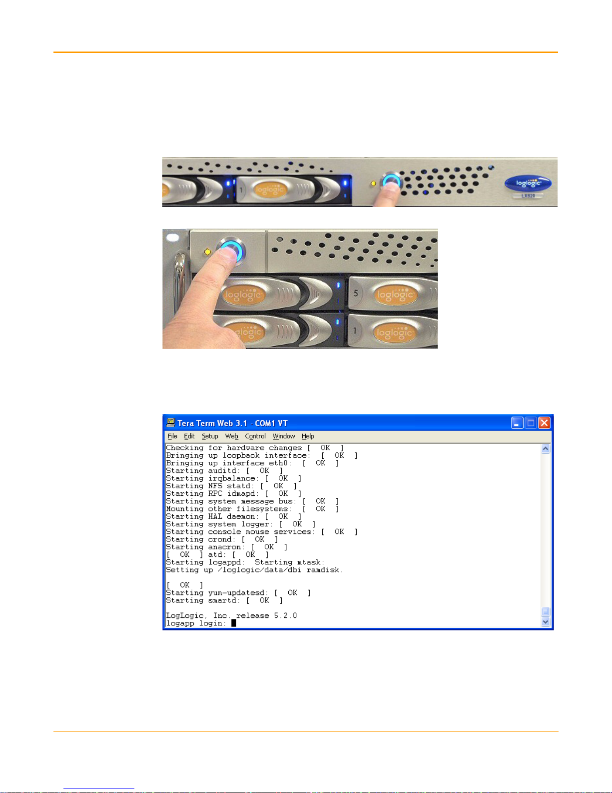
Step 4: Power up the Appliance
1. Press the Power button (located on the front side). In few seconds, the Power button
turns blue as shown below. When the operating system starts booting up, the LEDs
show blue color.
Figure 16 Power Button (for 1U system)
Figure 17 Power Button (for 2U system)
2. Wait for about 3 to 5 minutes for system to boot up. During this time, you can see
various messages appearing on the screen. Once the system boots up, the screen
displays the following prompt.
Figure 18 Appliance Booting Process Completed
Congratulations! You have successfully installed the LogLogic Appliance.
Step 5: Log into the Appliance
For instructions on how to log in to the Appliance using either Web browser or Console,
refer to the LogLogic Installation and Upgrade Guide.
8

APPENDIX A
External Hardware Descriptions
This appendix provides a series of graphics displaying the external hardware and
provides the hardware specifications for the LogLogic™ family of products. Sorted by
Appliance family, every model is described.
Contents
LX Product Family. . . . . . . . . . . . . . . . . . . . . . . . . . . . . . . . . . . . . . . . . . . . . . . . . . . . . 10
ST Product Family . . . . . . . . . . . . . . . . . . . . . . . . . . . . . . . . . . . . . . . . . . . . . . . . . . . . 14
MX Product Family . . . . . . . . . . . . . . . . . . . . . . . . . . . . . . . . . . . . . . . . . . . . . . . . . . . . 18
Note: All LogLogic 2U Appliances come with mounting slides that you can use to mount to a 19-inch
enclosed equipment rack. Hardware such as brackets and screws are provided to secure the
Appliances to the 19-inch equipment rack.
9

LX Product Family
LX Product Family
The LX product family includes the following Appliances:
LX 820
LX 1020
LX 4020
LX Product Family Specifications
Hardware Specifications LX 820 LX 1020 LX 4020
CPU Quad Core Xeon Quad Core Xeon Dual Quad Core Xeon
Memory 4 GB 6 GB 12 GB
Hard Drive 2x500 GB 2x1 TB 8x1 TB
RAID * RAID 1 RAID 1 RAID 10
AC Power Connections 1 2 (for redundancy) 2 (for redundancy)
AC Input 100-240 V
50-60 Hz
Power Consumption 120 Watts 160 Watts 440 Watts
Heat Dissipation 410 BTU/hr 550 BTU/hr 1500 BTU/hr
AC Current 1.15 A @ 120V 1.35 A @ 120V 3.3A @ 120V
Operating Altitude -50 to 10,000 ft
-16 to 3048 m
Operating Temperature
Relative Humidity
19” Rack Mount Chassis 1U 1U 2U
Chassis Mounting Rail kit provided.
Chassis (W x H x D)
10-35 degrees C. (Derate maximum temperature by 1 degree C per 300 meters above sea
level)
20-80% non-condensing
Rails adjust 28” to 31” and attach to front and rear of rack or cabinet.
Caution: Rails cannot be properly mounted if adjusted to under 28”.
17.5 x 1.75 x 21 inches
(44.50 x 4.45 x 53.30 cm)
Weight 22 lb / 10.00 kg 28 lb / 12.73 kg 52 lb / 23.64 kg
Ethernet 3x10/100/1000 6x10/100/1000 6x10/100/1000
Bonding Port Labeling Eth0 & Eth1 Eth2 & Eth3; Eth4 & Eth5 Eth2 & Eth3;
Console Connector (male) (null modem
cable provided)
* 2U Appliance RAID includes a cache memory with internal battery backup. In the event of an unplanned power outage, the battery
will protect the integrity of the disk data for a maximum of 72 hours.
9-pin D-sub 9-pin D-sub 9-pin D-sub
100-240 V
50-60 Hz
-50 to 10,000 ft
-16 to 3048 m
17.25 x 1.75 x 27 inches
(43.82 x 4.45 x 68.58 cm)
100-240 V
50-60 Hz
-50 to 10,000 ft
-16 to 3048 m
17.5 x 3.5 x 28 inches (44.45 x
8.89 x 71.12 cm)
Eth4 & Eth5
10

LX 820 Appliance
A
B
CD
E F/G H I J
LX 820 Front Panel
ID Description
A Attention LED
B Power Button
LX 820 Rear Panel
APPENDIX A External Hardware Descriptions
ID Description
CPower Source
D Cooling Fan
E USB Ports (x4)
FVideo Port
GSerial Port
HEth 2 Port
IEth 0 Port
JEth 1 Port
11

LX Product Family
A
B
CD E
F G/H F I J K L
LX 1020 Appliance
LX 1020 Front Panel
ID Description
A Attention LED
B Power Button
LX 1020 Rear Panel
ID Description
C Cooling Fan
DPower Source
EAlarm Reset
F USB Ports (x2)
GVideo Port
HSerial Port
I Eth 3 and Eth 2 Ports
J Eth 1 and Eth 0 Ports
K, L Eth 5 and Eth 4 Ports
12

LX 4020 Appliance
A
B
CD E
FG/H I J KF
LX 4020 Front Panel
ID Description
A Attention LED
B Power Button
LX 4020 Rear Panel
APPENDIX A External Hardware Descriptions
ID Description
C Power Module
DPower Source
EAlarm Reset
F USB Ports (x2)
GVideo Port
HSerial Port
I Eth 3 & Eth 2 Ports
J Eth 1 & Eth 0 Ports
K Eth 4 & Eth 5 Ports
13

ST Product Family
ST Product Family
The ST product family includes the following Appliances:
ST 1020
ST 2020-SAN (Storage Area Network)
ST 4020
ST Product Family Specifications
Hardware Specifications ST 1020 ST 2020-SAN ST 4020
CPU Quad Core Xeon 2 Quad Xeon Dual Quad Core Xeon
Memory 6 GB 12 GB 12 GB
Hard Drive 2x1 TB 2x1 TB 8x1 TB
* RAID 1 RAID 1 RAID 5 + Spare
RAID
AC Power Connections 2 (for redundancy) 2 (for
redundancy)
AC Input 100-240 V
50-60 Hz
Power Consumption 160 Watts 270 Watts 450 Watts
Heat Dissipation 550 BTU/hr 950 BTU/hr 1500 BTU/hr
AC Current 1.3 A @ 120V 2.2 A @ 120V 3.3 A @ 120V
Operating Altitude -50 to 10,000 ft
-16 to 3048 m
Operating Temperature
Relative Humidity 20-80% non-condensing
19” Rack Mount Chassis 1U 1U 2U
Chassis mounting Rail kit provided.
Chassis (W x H x D) 17.25 x 1.75 x 27 inches
Weight 28 lb / 12.73 kg 30 lb / 13.64 kg 52 lb / 23.64 kg
Ethernet 6x10/100/1000 4x10/100/1000 6x10/100/1000
Bonding Port Labeling Eth2&3; Eth4&5 Eth2&3/FC1&2 Eth2&3; Eth4&5
Console Connector (male) (null
modem cable provided)
10-35 degrees C.
(Derate maximum temperature by 1 degree C per 300 meters above sea level)
Each rail adjusts from 28” to 31” and attaches to front and rear of rack or cabinet.
Caution: Rails cannot be properly mounted if adjusted to under 28”.
(43.82 x 4.45 x 68.58 cm)
9-pin D-sub 9-pin D-sub 9-pin D-sub
100-240 V
50-60 Hz
-50 to 10,000 ft
-16 to 3048 m
17.25 x 1.75 x 27 inches
(43.82 x 4.45 x 68.58 cm)
2 (for
redundancy)
100-240 V
50-60 Hz
-50 to 10,000 ft
-16 to 3048 m
17.50 x 3.50 x 28 inches (44.45 x
8.89 x 71.12 cm)
* 2U Appliance RAID includes a cache memory with internal battery backup. In the event of an unplanned power outage, the
battery will protect the integrity of the disk data for a maximum of 72 hours.
14

ST 1020 Appliance
A
B
CD E
F G/H F I J K L
ST 1020 Front Panel
ID Description
A Attention LED
B Power Button
ST 1020 Rear Panel
APPENDIX A External Hardware Descriptions
ID Description
C Cooling Fan (x2)
DPower Source (x2)
EAlarm Reset
F USB Ports (x2)
GVideo Port
HSerial Port
I Eth 3 and Eth 2 Ports
J Eth 1 and Eth 0 Ports
K, L Eth 5 and Eth 4 Ports
15

ST Product Family
A
B
ST 2020-SAN Appliance
ST 2020-SAN Front Panel
ID Description
A Attention LED
B Power Button
ST 2020-SAN Rear Panel
C D E F G / H F I /J K /L FC 1& 2
ID Description
C Cooling Fan
DPower Source (x2)
EAlarm Reset
F USB Ports (x2)
GVideo Port
HSerial Port
I Eth 3 Port
JEth 2 Port
KEth 1 Port
LEth 0 Port
FC Fibre Channel 1 & 2
Supported Optical Cable Distances & Types
Cable Type and Distance (meters)
Rate OM1 OM2 OM3
2Gbps 150 300 500
4Gbps 70 150 380
8Gbps 121 50 150
16

ST 4020 Appliance
A
B
CD E
FG/H I J KF
ST 4020 Front Panel
ID Description
A Attention LED
B Power Button
ST 4020 Rear Panel
APPENDIX A External Hardware Descriptions
ID Description
C Power Module
DPower Source
EAlarm Reset
F USB Ports (x2)
GVideo Port
HSerial Port
I Eth 3 & Eth 2 Ports
J Eth 1 & Eth 0 Ports
K Eth 4 & Eth 5 Ports
17

MX Product Family
MX Product Family
The MX product family contains the MX 3020 and MX 4020 Appliances.
MX Product Family Specifications
Hardware Specifications MX 3020 MX 4020
CPU Quad Core Xeon Dual Quad Core Xeon
Memory 6 GB 12 GB
Hard Drive 8x500 GB 8 TB
* RAID 10 RAID 10
RAID
AC Power Connections 2 (for redundancy) 2 (for redundancy)
AC Input 100-240 V
50-60 Hz
Power Consumption 450 Watts 440 Watts
Heat Dissipation 1500 BTU/hr 1500 BTU/hr
AC Current 3.3A @ 120V 3.3A @ 120V
Operating Altitude -50 to 10,000 ft
-16 to 3048 m
Operating Temperature 10-35 degrees C. (Derate
maximum temparture by 1
degree C per 300 meters above
sea level)
Relative Humidity 20-80% non-condensing 20-80% non-condensing
19” Rack Mount Chassis 2U 2U
Chassis Mounting Rail kit provided.
Each rail adjusts from 28” to 31”
and attaches to front and rear of
rack or cabinet.
Caution: Rails cannot be
properly mounted if adjusted to
under 28”.
Chassis (W x H x D) 17.5 x 3.5 x 28 inches
44.45 x 8.89 x 71.12 cm
Weight 52 lb / 23.64 kg 52 lb / 23.64 kg
Ethernet 6x10/100/1000 6x10/100/1000
Bonding Port Labeling Eth2&3/Eth4&5 Eth2&3/Eth4&5
Console Connector (male)
(null modem cable provided)
9-pin D-sub 9-pin D-sub
100-240 V
50-60 Hz
-50 to 10,000 ft
-16 to 3048 m
10-35 degrees C.
Rail kit provided.
Each rail adjusts from 28” to 31”
and attaches to front and rear of
rack or cabinet.
Caution: Rails cannot be
properly mounted if adjusted to
under 28”.
17.5 x 3.5 x 28 inches
44.45 x 8.89 x 71.12 cm
* 2U Appliance RAID includes a cache memory with internal battery backup. In the event of an
unplanned power outage, the battery will protect the integrity of the disk data for a maximum of 72
hours.
18

MX 3020/MX4020 Appliance
A
B
CD E
FG/H I J KF
Note: The pictures below represents MX3020 Appliance.
MX 3020/MX 4020 Front Panel
ID Description
A Attention LED
B Power Button
APPENDIX A External Hardware Descriptions
MX 3020/MX 4020 Rear Panel
ID Description
C Power Module
DPower Source
EAlarm Reset
F USB Ports (x2)
GVideo Port
HSerial Port
I Eth 3 & Eth 2 Ports
J Eth 1 & Eth 0 Ports
K Eth 4 & Eth 5 Ports
19

MX Product Family
20

APPENDIX B
Battery Safety
Caution:
Danger of explosion if battery is incorrectly replaced.
Replace only with the same or equivalent type recommended by the manufacturer.
Discard used batteries according to the manufacturer’s instructions.
21

Battery Safety :
22
 Loading...