

Page 1
ELECTRONICS
Corporation, and shall not be distributed, reproduced, or disclosed in whole or in part without prior written
Global LCD Panel Exchange Center
www.panelook.com
One step solution for LCD / PDP / OLED panel application: Datasheet, inventory and accessory!
www.panelook.com
SHANGHAI AVIC OPTOELECTRONICS Q/S1016-2011
MODEL NO. : TM190MFS02
ISSUED DATE:
2012/05/10
VERSION : 1.0
□Preliminary Specification
■Final Product Specification
Customer :
Approved by N
SHANGHAI AVIC Confirmed :
Prepared by Approved by
Pean Wu Hyman Chen
otes
This technical specification is subjected to change without notice
The information contained herein is the exclusive property of SHANGHAI AVIC OPTO
permission of SHANGHAI AVIC OPTOELECTRONICS Corporation.
Page 1 of 25
Page 2

ELECTRONICS
Corporation, and shall not be distributed, reproduced, or disclosed in whole or in part without prior written
Global LCD Panel Exchange Center
www.panelook.com
One step solution for LCD / PDP / OLED panel application: Datasheet, inventory and accessory!
www.panelook.com
SHANGHAI AVIC OPTOELECTRONICS Q/S1016-2011
TABLE OF CONTENTS
1. OUTLINE ................................................................................................................................................................................ 4
2. GENERAL SPECIFICATIONS ............................................................................................................................................. 5
3. ABSOLUTE MAXIMUM RATINGS .................................................................................................................................... 6
4. BLOCK DIAGRAM ............................................................................................................................................................... 7
5. MECHANICAL SPECIFICATIONS .................................................................................................................................... 8
6. ELECTRICAL CHARACTERISTICS ................................................................................................................................. 9
7. CONNECTIONS AND FUNCTIONS FOR INTERFACE PINS ...................................................................................... 10
8. DISPLAY COLORS AND INPUT DATA SIGNALS.......................................................................................................... 12
9. INTERFACE TIMING ......................................................................................................................................................... 13
10. OPTICS ................................................................................................................................................................................ 18
11. MARKINGS ......................................................................................................................................................................... 21
12. PRECAUTIONS .................................................................................................................................................................. 24
13. OUTDRAWING .................................................................................................................................................................. 25
The information contained herein is the exclusive property of SHANGHAI AVIC OPTO
permission of SHANGHAI AVIC OPTOELECTRONICS Corporation.
Page 2 of 25
Page 3
ELECTRONICS
Corporation, and shall not be distributed, reproduced, or disclosed in whole or in part without prior written
Global LCD Panel Exchange Center
www.panelook.com
One step solution for LCD / PDP / OLED panel application: Datasheet, inventory and accessory!
www.panelook.com
SHANGHAI AVIC OPTOELECTRONICS Q/S1016-2011
Rev Issued Date Description Editor
1.0 2012-05-10 First issued Pean Wu
RECORD OF REVISION
The information contained herein is the exclusive property of SHANGHAI AVIC OPTO
permission of SHANGHAI AVIC OPTOELECTRONICS Corporation.
Page 3 of 25
Page 4

ELECTRONICS
Corporation, and shall not be distributed, reproduced, or disclosed in whole or in part without prior written
Global LCD Panel Exchange Center
www.panelook.com
One step solution for LCD / PDP / OLED panel application: Datasheet, inventory and accessory!
www.panelook.com
SHANGHAI AVIC OPTOELECTRONICS Q/S1016-2011
1. OUTLINE
1.1 STRUCTURE AND PRINCIPLE
TM190MFS02 open cell is composed of the amorphous silicon thin film transistor liquid crystal display (a-Si
TFT LCD) panel structure with driver LSIs for driving the TFT (Thin Film Transistor) array. The a-Si TFT LCD panel
structure is injected liquid crystal material into a narrow gap between the TFT array glass substrate and a color-filter
glass substrate.
Color (Red, Green, Blue) data signals from a host system (e.g. PC, signal generator, etc.) are modulated into
best form for active matrix system by a signal processing board, and sent to the driver LSIs which drive the individual
TFT arrays. The TFT array as an electro-optical switch regulates the amount of transmitted light from the backlight
assembly, when it is controlled by data signals. Color images are created by regulating the amount of transmitted light
through the TFT array of red, green and blue dots.
1.2 APPLICATIONS
• Monitor
1.3 FEATURES
• a-Si TFT active matrix
LVDS interface
•
• R.G.B input 8bit, 16.7 millions colors (6bit+Hi-FRC)
• Resolution WXGA+ (1,440× 900 pixels)
• High contrast ratio 600 :1
)
• Fast response time (Ton+ Toff= 5 ms
The information contained herein is the exclusive property of SHANGHAI AVIC OPTO
permission of SHANGHAI AVIC OPTOELECTRONICS Corporation.
Page 4 of 25
Page 5
ELECTRONICS
Corporation, and shall not be distributed, reproduced, or disclosed in whole or in part without prior written
Global LCD Panel Exchange Center
www.panelook.com
One step solution for LCD / PDP / OLED panel application: Datasheet, inventory and accessory!
www.panelook.com
SHANGHAI AVIC OPTOELECTRONICS Q/S1016-2011
2. GENERAL SPECIFICATIONS
Display area 408.24 (H) × 255.15 (V) mm (typ.)
Diagonal size of display 480 mm (19.0 inches)
Drive system a-Si TFT active matrix
Display color 16.7 M colors (6bit+ Hi-FRC)
Pixel 1,440 (H) × 900(V) pixels
Pixel arrangement
Pixel pitch 0.2835 (H) × 0.2835 (V) mm
Signal system
Power supply voltage LCD panel signal processing board: 5.0V
Transmissive Mode
Response time
Contrast ratio
Surface Treatment
RGB vertical stripe
LVDS 2port
Normally White
5 ms (typ.)
600 :1 (typ.)
Anti Glare
The information contained herein is the exclusive property of SHANGHAI AVIC OPTO
permission of SHANGHAI AVIC OPTOELECTRONICS Corporation.
Page 5 of 25
Page 6
ELECTRONICS
Corporation, and shall not be distributed, reproduced, or disclosed in whole or in part without prior written
Temperature (
℃℃℃℃
)
Global LCD Panel Exchange Center
www.panelook.com
One step solution for LCD / PDP / OLED panel application: Datasheet, inventory and accessory!
www.panelook.com
SHANGHAI AVIC OPTOELECTRONICS Q/S1016-2011
3. ABSOLUTE MAXIMUM RATINGS
Parameter Symbol
Power supply voltage
Input voltage for signals Vi -0.3 ~ +3.6 V Ta = 25°C
Storage temperature Tst -20 ~ +60 °C Note 3
Operating temperature Top 0 ~ +50 °C Note 3, 4
Absolute humidity AH ≤ 70 g/m3 Ta > 50°C
Operating altitude - ≤ 4,850 m 0°C≤ Ta≤ 50°C
Storage altitude - ≤ 13,600 m -20°C≤ Ta≤ 60°C
Note1: Display signals are DA0+/-, DA1+/-, DA2+/-, DA3+/-, CKA+/-, DB0+/-, DB1+/-, DB2+/-, DB3+/-,
VDD -0.3 ~ +3.6 V Ta = 25°C
Rating Unit Remarks
and CKB+/-.
Note2: Function signal is MSL.
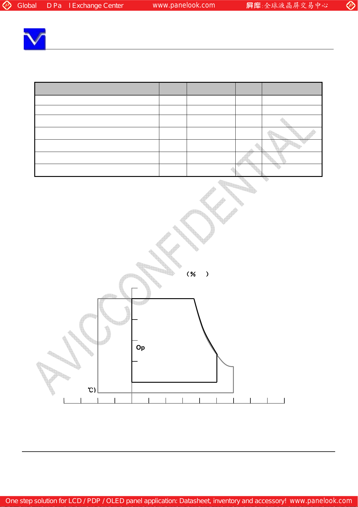
Note3: Temperature and relative humidity range is shown in the figure below.
(a) 90%RH Max. (Ta≤ 40°C)
(b) Wet-bulb temperature should be39°C Max. (Ta> 40°C)
(c) No condensation.
Note4: The temperature of panel display surface area should be 0°C Min and 60°C Max.
-40 -20 0 20 40 60 80
Relative Humidity
80
60
Operating Range
40
20
5
Storage Range
(%
(%RH))))
(%(%
The information contained herein is the exclusive property of SHANGHAI AVIC OPTO
permission of SHANGHAI AVIC OPTOELECTRONICS Corporation.
Page 6 of 25
Page 7
ELECTRONICS
Corporation, and shall not be distributed, reproduced, or disclosed in whole or in part without prior written
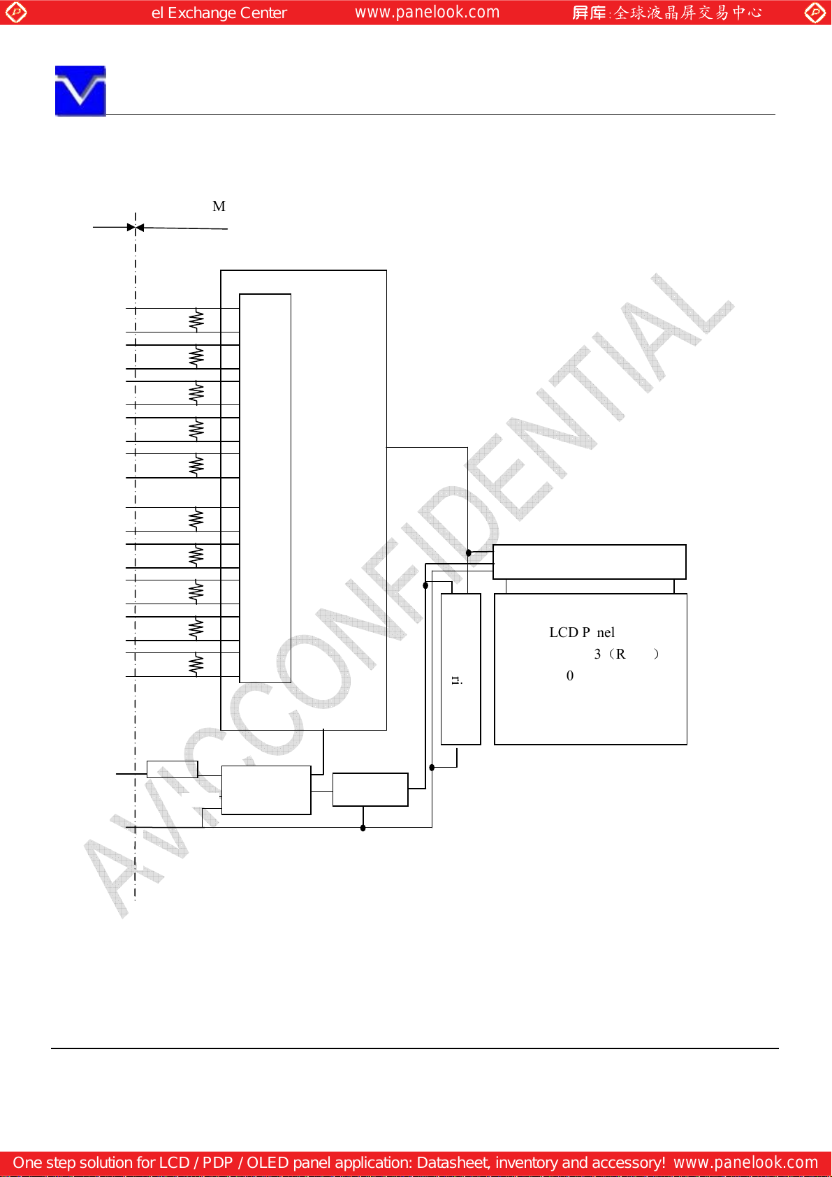
VDD
DC/DC
Gate Driver
GND
Global LCD Panel Exchange Center
www.panelook.com
One step solution for LCD / PDP / OLED panel application: Datasheet, inventory and accessory!
www.panelook.com
SHANGHAI AVIC OPTOELECTRONICS Q/S1016-2011
4. BLOCK DIAGRAM
I/F
DA0+
D
A0-
DA1+
DA1-
DA2+
DA2-
CKA+
CKA-
DA3+
DA3-
DB0+
DB0-
DB1+
DB1-
DB2+
DB2-
CKB+
CKA-
DB3+
DB3-
LCD MODULE
100Ω
100Ω
100Ω
100Ω
100Ω
100Ω
100Ω
100Ω
100Ω
100Ω
Timing Controller
LVDS Receiver
Source Driver
H: 1440× 3(R,G,B)
V: 900
LCD Panel
Converter
Power
`
Note: System ground (GND), FG (Frame ground) in the product should be connected together in customer
pment.
equi
The information contained herein is the exclusive property of SHANGHAI AVIC OPTO
permission of SHANGHAI AVIC OPTOELECTRONICS Corporation.
Page 7 of 25
Page 8
ELECTRONICS
Corporation, and shall not be distributed, reproduced, or disclosed in whole or in part without prior written
Global LCD Panel Exchange Center
www.panelook.com
One step solution for LCD / PDP / OLED panel application: Datasheet, inventory and accessory!
www.panelook.com
SHANGHAI AVIC OPTOELECTRONICS Q/S1016-2011
5. MECHANICAL SPECIFICATIONS
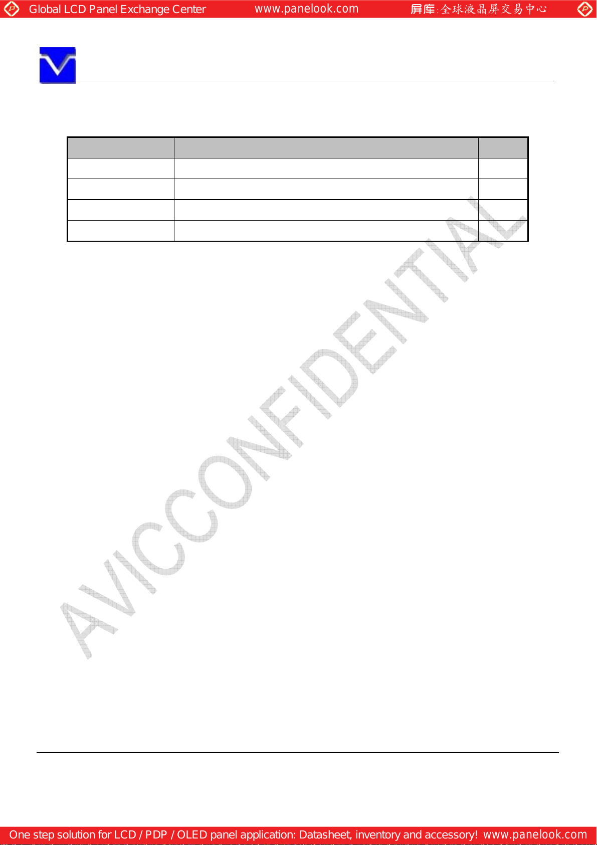
Parameter Specification Unit
Display area 408.24(H) × 255.15(V) mm (typ.), [48.0 cm (19.0 inches)]
Display dot number 1440×3(H) ×900(V) -
Pixel pitch 0.2835(H)×0.2835(V) mm
Dot pitch 0.0945(H) ×0.2835(V) mm
mm
The information contained herein is the exclusive property of SHANGHAI AVIC OPTO
permission of SHANGHAI AVIC OPTOELECTRONICS Corporation.
Page 8 of 25
Page 9
ELECTRONICS
Corporation, and shall not be distributed, reproduced, or disclosed in whole or in part without prior written
Global LCD Panel Exchange Center
www.panelook.com
One step solution for LCD / PDP / OLED panel application: Datasheet, inventory and accessory!
www.panelook.com
SHANGHAI AVIC OPTOELECTRONICS Q/S1016-2011
6. ELECTRICAL CHARACTERISTICS
Parameter Symbol min. typ. max. Unit
Remarks
Power supply voltage VDD 4.5 5.0 5.5 V -
Power supply current IDD -
700
Note1
1000
Note 2
mA at VDD = 5.0V
Permissible ripple voltage VRP - - 200 mV VDD
Differential input voltage
Differential input threshold
voltage for LVDS receiver
︱
Vid
Low VTL -100 - - mV
High VTH - - 100 mV
200 600 mV
︱
at VCM = 1.2V
Note3
Input voltage width for LVDS receiver Vi 0 - 3.3 V -
Terminating resistor RT - 100 - Ω -
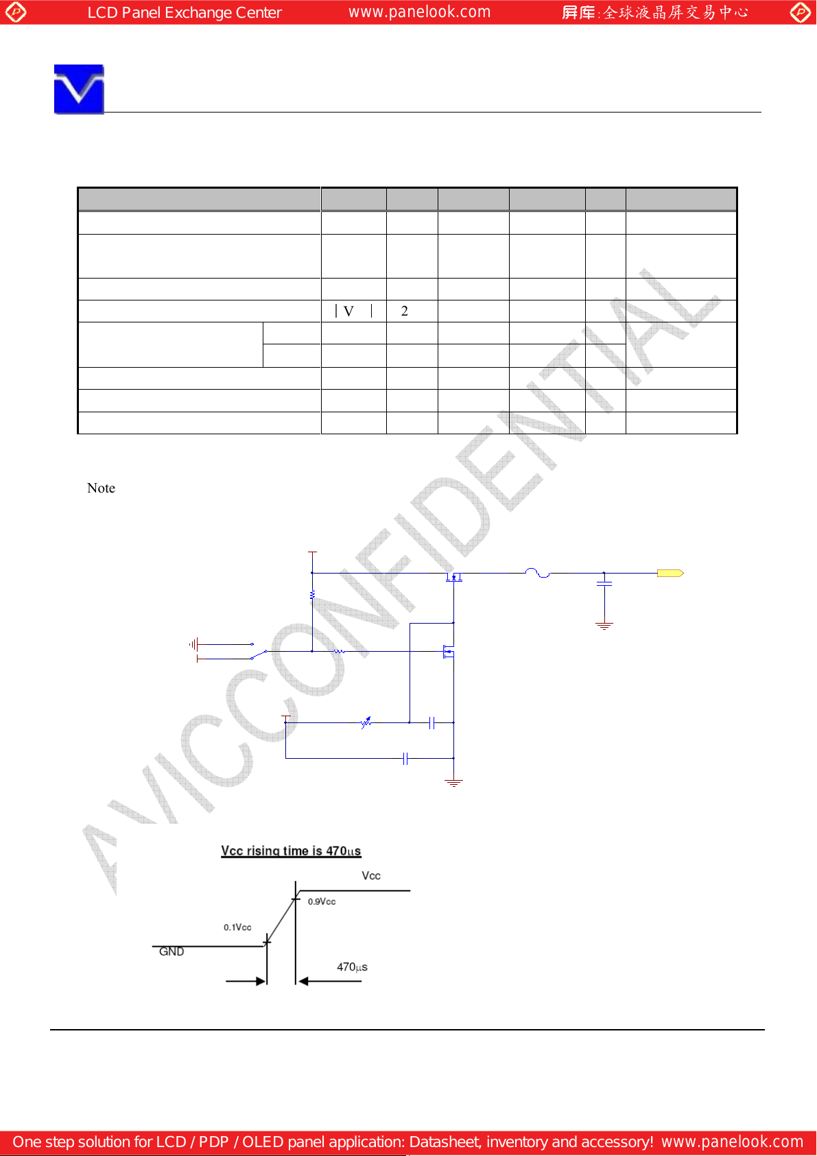
Rush current I
- - 3.0 A Note4
rush
Note 1: Black pattern
Note 2: 1H1V dot inverse pattern
Note 3: Common mode voltage for LVDS receiver
Note4: Measurement Conditions:
5V
F1
Fuse(2A)
C1
Cap
1uF/16V
VDD
R1
47K
Q1
MOSFET-N
GND
S2
1
2
5V
3
SW-SPDT
12V
R2
1K
R3
20K
C3
Cap
10uF/16V
C2
Cap
1uF/16V
Q2
MOSFET-N
GND
GND
The information contained herein is the exclusive property of SHANGHAI AVIC OPTO
permission of SHANGHAI AVIC OPTOELECTRONICS Corporation.
Page 9 of 25
Page 10
ELECTRONICS
Corporation, and shall not be distributed, reproduced, or disclosed in whole or in part without prior written
Global LCD Panel Exchange Center
www.panelook.com
One step solution for LCD / PDP / OLED panel application: Datasheet, inventory and accessory!
www.panelook.com
SHANGHAI AVIC OPTOELECTRONICS Q/S1016-2011
7. CONNECTIONS AND FUNCTIONS FOR INTERFACE PINS
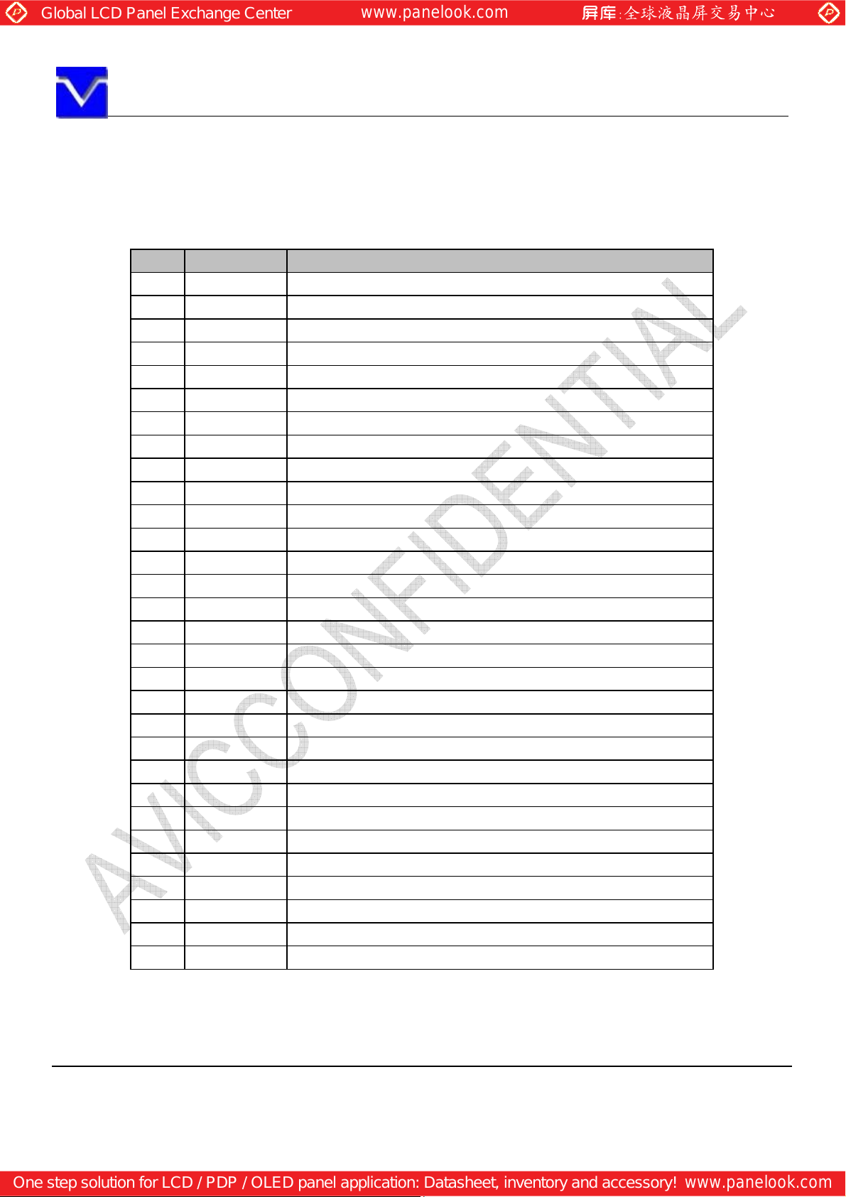
7.1 LVDS
CN1: FI-XB30SSRLA-HF16 (Produced by JAE) or equivalent.
Pin Name Description
1 RXO0- Negative LVDS differential data input. Channel O0 (odd)
2 RXO0+ Positive LVDS differential data input. Channel O0 (odd)
3 RXO1- Negative LVDS differential data input. Channel O1 (odd)
4 RXO1+ Positive LVDS differential data input. Channel O1 (odd)
5 RXO2- Negative LVDS differential data input. Channel O2 (odd)
6 RXO2+ Positive LVDS differential data input. Channel O2 (odd)
7 GND Ground
8 RXOC- Negative LVDS differential clock input. (odd)
9 RXOC+ Positive LVDS differential clock input. (odd)
10 RXO3- Negative LVDS differential data input. Channel O3(odd)
11 RXO3+ Positive LVDS differential data input. Channel O3 (odd)
12 RXE0- Negative LVDS differential data input. Channel E0 (even)
13 RXE0+ Positive LVDS differential data input. Channel E0 (even)
14 GND Ground
15 RXE1- Negative LVDS differential data input. Channel E1 (even)
16 RXE1+ Positive LVDS differential data input. Channel E1 (even)
17 GND Ground
18 RXE2- Negative LVDS differential data input. Channel E2 (even)
19 RXE2+ Positive LVDS differential data input. Channel E2 (even)
20 RXEC- Negative LVDS differential clock input. (even)
21 RXEC+ Positive LVDS differential clock input. (even)
22 RXE3- Negative LVDS differential data input. Channel E3 (even)
23 RXE3+ Positive LVDS differential data input. Channel E3 (even)
24 GND Ground
25 GND Ground
26 NC Not connection.
27 GND Ground
28 VDD +5.0V power supply
29 VDD +5.0V power supply
30 VDD +5.0V power supply
The information contained herein is the exclusive property of SHANGHAI AVIC OPTO
permission of SHANGHAI AVIC OPTOELECTRONICS Corporation.
Page 10 of 25
Page 11
ELECTRONICS
Corporation, and shall not be distributed, reproduced, or disclosed in whole or in part without prior written
Global LCD Panel Exchange Center
www.panelook.com
One step solution for LCD / PDP / OLED panel application: Datasheet, inventory and accessory!
www.panelook.com
SHANGHAI AVIC OPTOELECTRONICS Q/S1016-2011
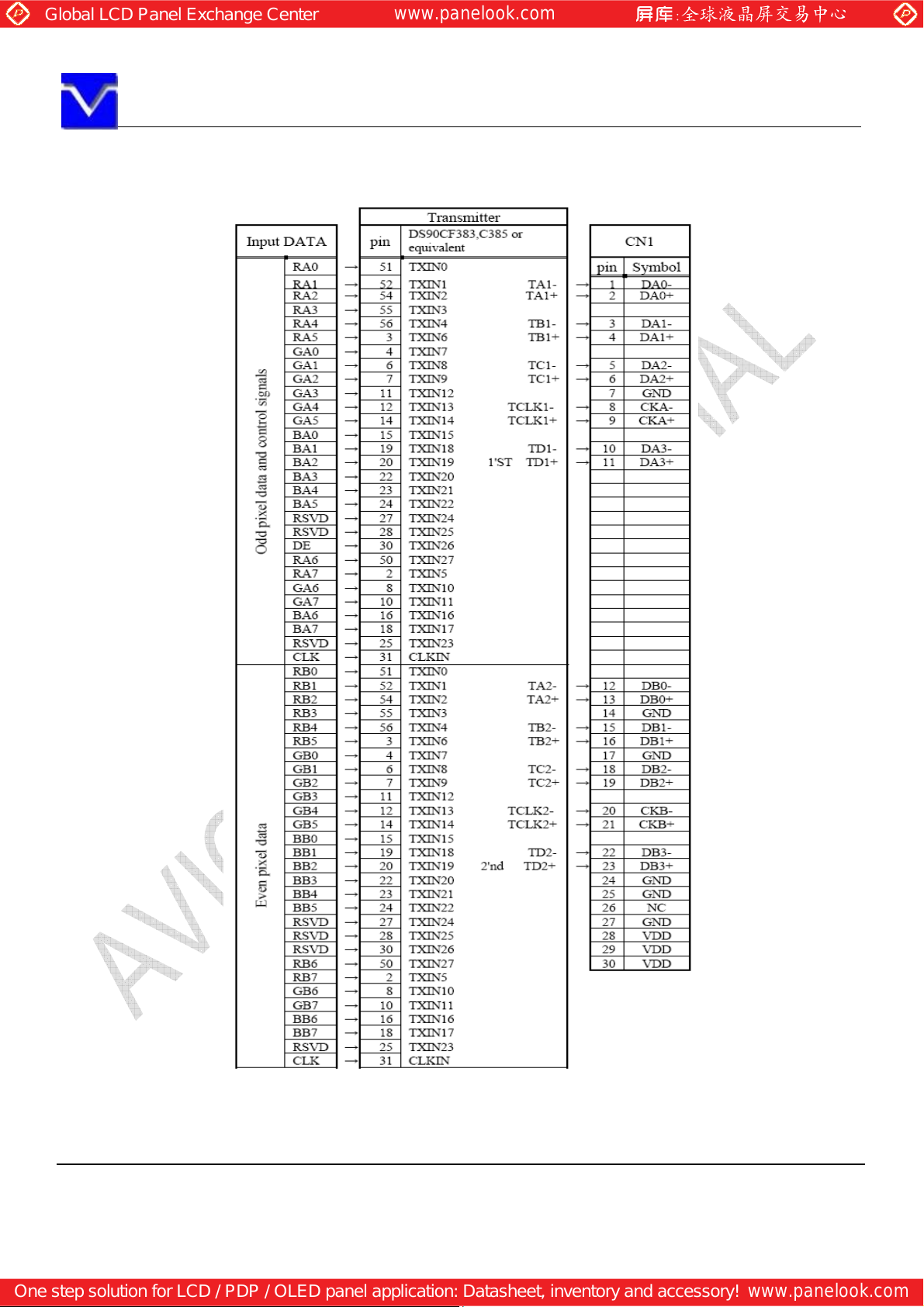
7.2 CONNECTION BETWEEN RECEIVER AND TRANSMITTER FOR LVDS
Note1: The lowest bit (RA0, GA0, BA0, RB0, GB0, BB0), the most upper bit (RA7, GA7, BA7, RB7, GB7, BB7)
Note2:Connecting cable between LCD panel’s connector and transmitter should use 100Ω twisted line.
Note3: If only Hsync and Vsync, the product don’t work. Make sure DE signal has been input.
The information contained herein is the exclusive property of SHANGHAI AVIC OPTO
permission of SHANGHAI AVIC OPTOELECTRONICS Corporation.
Page 11 of 25
Page 12
ELECTRONICS
Corporation, and shall not be distributed, reproduced, or disclosed in whole or in part without prior written
Global LCD Panel Exchange Center
www.panelook.com
One step solution for LCD / PDP / OLED panel application: Datasheet, inventory and accessory!
www.panelook.com
SHANGHAI AVIC OPTOELECTRONICS Q/S1016-2011
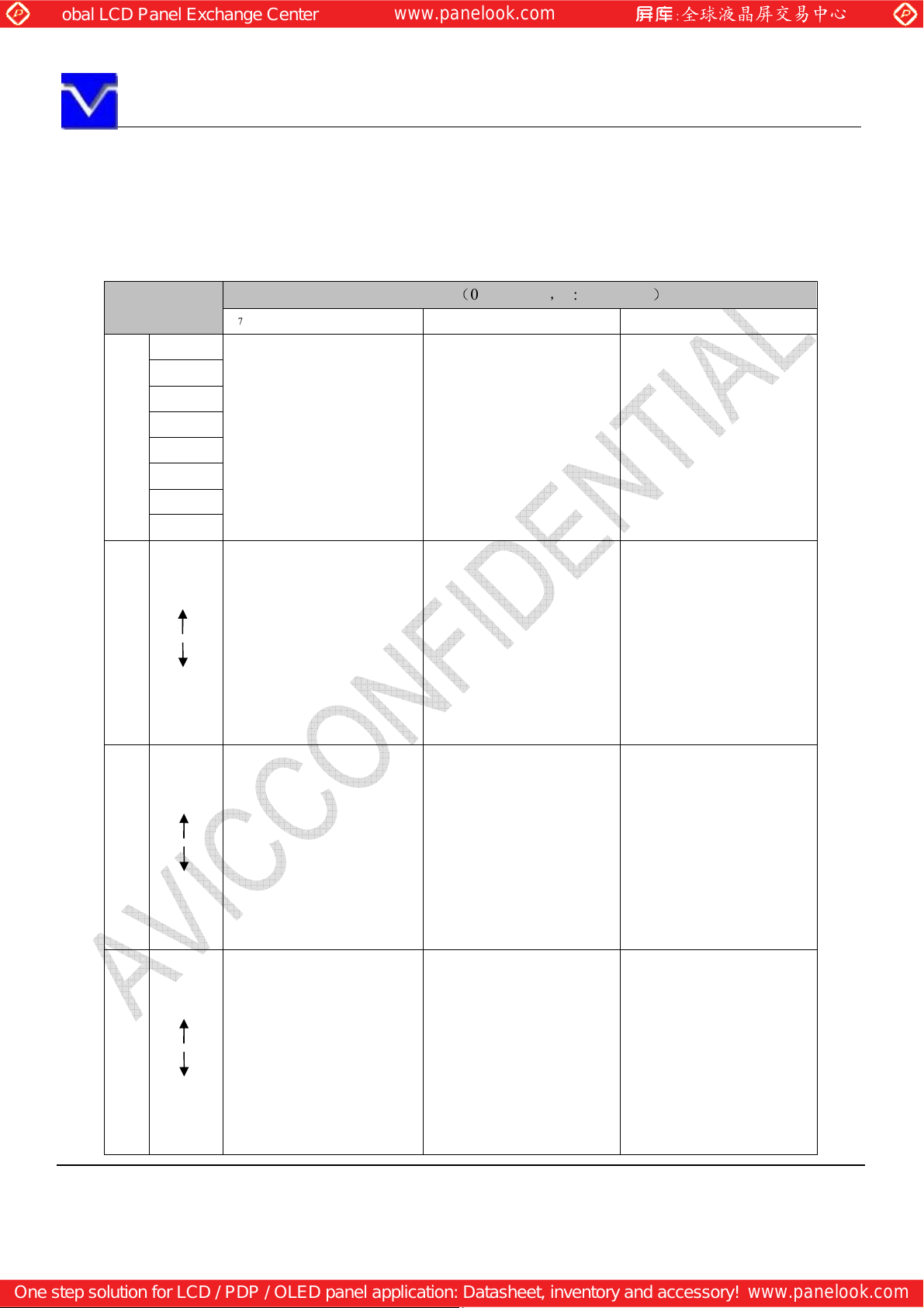
8. DISPLAY COLORS AND INPUT DATA SIGNALS
This product can display in equivalent to 16,777,216 colors in 256 scales. Also the relation between display
colors and input data signals is as the following table.
Display colors
Black 0 0 0 0 0 0 0 0 0 0 0 0 0 0 0 0 0 0 0 0 0 0 0 0
Blue 0 0 0 0 0 0 0 0 0 0 0 0 0 0 0 0 1 1 1 1 1 1 1 1
Red 1 1 1 1 1 1 1 1 0 0 0 0 0 0 0 0 0 0 0 0 0 0 0 0
Magenta 1 1 1 1 1 1 1 1 0 0 0 0 0 0 0 0 1 1 1 1 1 1 1 1
Green 0 0 0 0 0 0 0 0 1 1 1 1 1 1 1 1 0 0 0 0 0 0 0 0
Basic Color
Cyan 0 0 0 0 0 0 0 0 1 1 1 1 1 1 1 1 1 1 1 1 1 1 1 1
Yellow 1 1 1 1 1 1 1 1 1 1 1 1 1 1 1 1 0 0 0 0 0 0 0 0
White 1 1 1 1 1 1 1 1 1 1 1 1 1 1 1 1 1 1 1 1 1 1 1 1
Black
Dark
Bright
Red grayscale
Red
Black
Dark
Bright
Green grayscale
Green
Black
Dark
Bright
Blue grayscale
Blue
R7 R6 R5 R4 R3 R2 R1 R0 G7 G6 G5 G4 G3 G2 G1 G0 B7 B6 B5 B4 B3 B2 B1 B0
0 0 0 0 0 0 0 0 0 0 0 0 0 0 0 0 0 0 0 0 0 0 0 0
0 0 0 0 0 0 0 1 0 0 0 0 0 0 0 0 0 0 0 0 0 0 0 0
0 0 0 0 0 0 1 0 0 0 0 0 0 0 0 0 0 0 0 0 0 0 0 0
1 1 1 1 1 1 0 1 0 0 0 0 0 0 0 0 0 0 0 0 0 0 0 0
1 1 1 1 1 1 1 0 0 0 0 0 0 0 0 0 0 0 0 0 0 0 0 0
1 1 1 1 1 1 1 1 0 0 0 0 0 0 0 0 0 0 0 0 0 0 0 0
0 0 0 0 0 0 0 0 0 0 0 0 0 0 0 0 0 0 0 0 0 0 0 0
0 0 0 0 0 0 0 0 0 0 0 0 0 0 0 1 0 0 0 0 0 0 0 0
0 0 0 0 0 0 0 0 0 0 0 0 0 0 1 0 0 0 0 0 0 0 0 0
0 0 0 0 0 0 0 0 1 1 1 1 1 1 0 1 0 0 0 0 0 0 0 0
0 0 0 0 0 0 0 0 1 1 1 1 1 1 1 0 0 0 0 0 0 0 0 0
0 0 0 0 0 0 0 0 1 1 1 1 1 1 1 1 0 0 0 0 0 0 0 0
0 0 0 0 0 0 0 0 0 0 0 0 0 0 0 0 0 0 0 0 0 0 0 0
0 0 0 0 0 0 0 0 0 0 0 0 0 0 0 0 0 0 0 0 0 0 0 1
0 0 0 0 0 0 0 0 0 0 0 0 0 0 0 0 0 0 0 0 0 0 1 0
0 0 0 0 0 0 0 0 0 0 0 0 0 0 0 0 1 1 1 1 1 1 0 1
0 0 0 0 0 0 0 0 0 0 0 0 0 0 0 0 1 1 1 1 1 1 1 0
0 0 0 0 0 0 0 0 0 0 0 0 0 0 0 0 1 1 1 1 1 1 1 1
: : :
: : :
: : :
: : :
: : :
: : :
Data signal (0:Low level,1:High Level)
The information contained herein is the exclusive property of SHANGHAI AVIC OPTO
permission of SHANGHAI AVIC OPTOELECTRONICS Corporation.
Page 12 of 25
Page 13
ELECTRONICS
Corporation, and shall not be distributed, reproduced, or disclosed in whole or in part without prior written
Horizontal
Global LCD Panel Exchange Center
www.panelook.com
One step solution for LCD / PDP / OLED panel application: Datasheet, inventory and accessory!
www.panelook.com
SHANGHAI AVIC OPTOELECTRONICS Q/S1016-2011
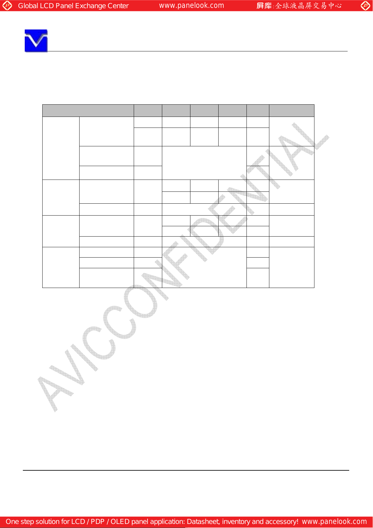
9. INTERFACE TIMING
9.1 TIMING CHARACTERISTICS
Parameter Symbol min. typ. max. Unit
Frequency
Clock
signals
Vertical
signals
DE/Data
Rise time, Fall
time
Duty - -
Cycle th
Display period thd 720 CLK
Cycle tv
Display period tvd 900 H -
Setup time -
Hold time - ns
Rise time, Fall
time
Note1: See the data sheet of LVDS transmitter.
1/tc 37.04 44.45 55.56 MHz
tc 27.0 22.50 18.0 ns
-
- ns
Refer to the timing
characteristics of LVDS
transmitter
14.8 18.0 26.5 s
754 800 900 CLK
13.3 16.67 20 ms
912 926 1100 H
Refer to the timing
characteristics of LVDS
transmitter
ns
ns
Remarks
LVDS
transmitter
input
Note 1
55.5kHz(typ.)
-
60.0Hz(typ.)
Note 1
The information contained herein is the exclusive property of SHANGHAI AVIC OPTO
permission of SHANGHAI AVIC OPTOELECTRONICS Corporation.
Page 13 of 25
Page 14
ELECTRONICS
Corporation, and shall not be distributed, reproduced, or disclosed in whole or in part without prior written
Global LCD Panel Exchange Center
www.panelook.com
One step solution for LCD / PDP / OLED panel application: Datasheet, inventory and accessory!
www.panelook.com
SHANGHAI AVIC OPTOELECTRONICS Q/S1016-2011
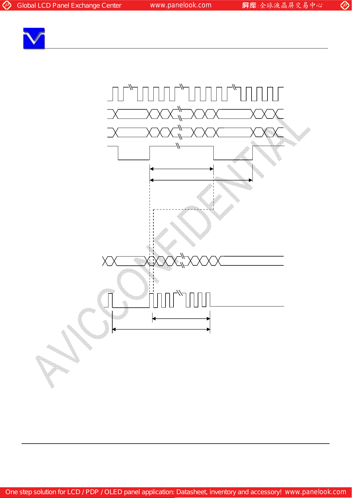
9.2 INPUT SIGNAL TIMING CHART
Horizontal timing
CLK
DATA(A) note1 Invalid 1 3 1437 1439 Invalid
DATA(B) Invalid 2 4 1438 1440 Invalid
DE
thd
Vertical timing
DATA(A),(B) Invalid Invalid
1 2 899 900
DE
tv
tvd
Note 1:
ATA(A)=RA0-RA7,GA0-GA7,BA0-BA7
D
DATA(B)=RB0-RB7,GB0-GB7,BB0-BB7
The information contained herein is the exclusive property of SHANGHAI AVIC OPTO
permission of SHANGHAI AVIC OPTOELECTRONICS Corporation.
Page 14 of 25
Page 15
ELECTRONICS
Corporation, and shall not be distributed, reproduced, or disclosed in whole or in part without prior written
GA
Global LCD Panel Exchange Center
www.panelook.com
One step solution for LCD / PDP / OLED panel application: Datasheet, inventory and accessory!
www.panelook.com
SHANGHAI AVIC OPTOELECTRONICS Q/S1016-2011
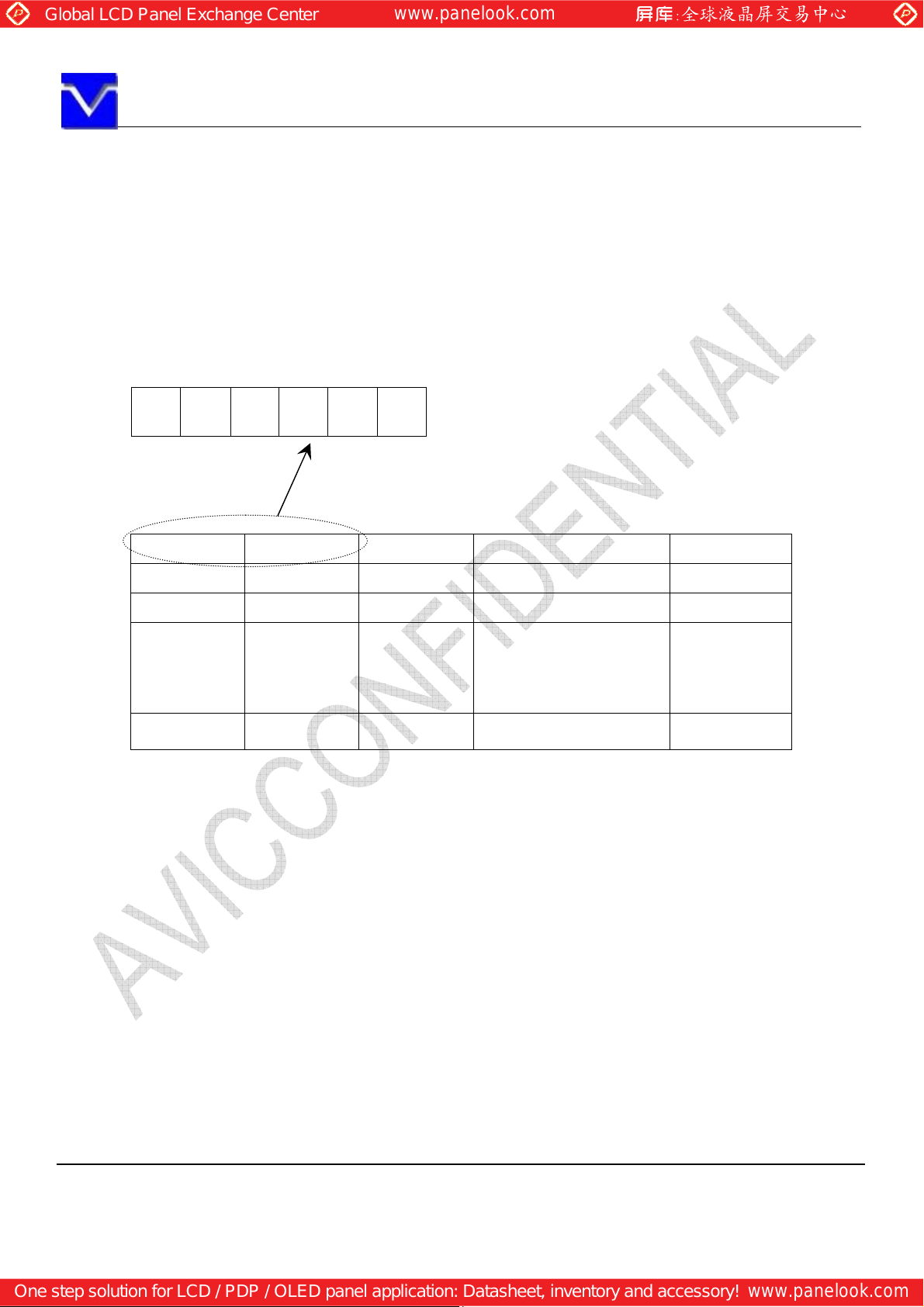
9.3 PIXEL DATA ALIGNMENT OF DISPLAY IMAGE
The following chart is the coordinates of per pixel
Odd Pixel: RA= R DATA
Even Pixel : RB=R DATA
GA= G DATA
BA= B DATA
D(1,1) D(2,1)
B
RA
D(1,1) D(2,1) D(3,1) ••• D(1440,1)
D(1,2) D(2,2) D(3,2) ••• D(1440,2)
D(1,3) D(2,3) D(3,3) ••• D(1440,3)
•
•
•
RB GB BB
A
•
•
•
•
•
•
GB=G DATA
BB=B DATA
•••
•••
•••
•
•
•
D(1,900) D(2,900) D(2,900) ••• D(1440,900)
The information contained herein is the exclusive property of SHANGHAI AVIC OPTO
permission of SHANGHAI AVIC OPTOELECTRONICS Corporation.
Page 15 of 25
Page 16
ELECTRONICS
Corporation, and shall not be distributed, reproduced, or disclosed in whole or in part without prior written
10%
ON
Global LCD Panel Exchange Center
www.panelook.com
One step solution for LCD / PDP / OLED panel application: Datasheet, inventory and accessory!
www.panelook.com
SHANGHAI AVIC OPTOELECTRONICS Q/S1016-2011
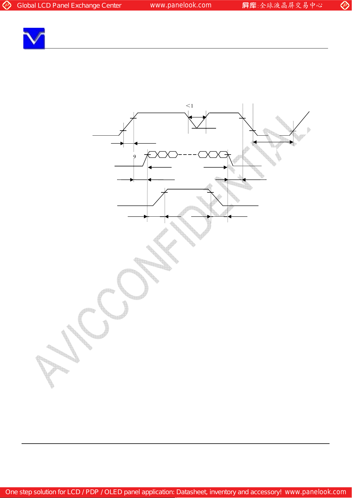
9.4. POWER SUPPLY VOLTAGE SEQUENCE
9.4.1 The sequence of backlight and power
t<10ms *1
VDD
0V
90%
4.5V
4.0V
t1
Display Signals*2
0V
Backlight signal
t5 t6
Timing Specifications:
t1 0.47ms<t1 <10ms
2 0.5 ms<t2 <50ms
t
t3 0ms<t3 <50ms
t4 >1000ms
t5 >200ms
t6 >200ms
*1. When VDD is on, but the value is lower than 4.5V, a protection circuit may work, then the module may not
display.
*2 The signal line is not connected with the module, at the end of cable the terminal resistor of 100 should be
added.
Note1: Display signals (D0+/-, D1+/-, D2+/-, D3+/- and CK+/-) must be “0” voltage, exclude the VALID period
(See above sequence diagram). If these signals are higher than 0.3 V, the internal circuit is damaged.
If some of display signals of this product are cut while this product is working, even if the signal input
to it once again, it might not work normally. If customer stops the display signals, they should cut VDD.
Note2: When VDD is on, it should be set above 4.0V.
Note3: The backlight power supply voltage should be inputted within the valid period of display and function
signals, in order to avoid unstable data display.
9.4.2 Power supply voltage ripple
The information contained herein is the exclusive property of SHANGHAI AVIC OPTO
permission of SHANGHAI AVIC OPTOELECTRONICS Corporation.
Page 16 of 25
Page 17
ELECTRONICS
Corporation, and shall not be distributed, reproduced, or disclosed in whole or in part without prior written
Global LCD Panel Exchange Center
www.panelook.com
One step solution for LCD / PDP / OLED panel application: Datasheet, inventory and accessory!
www.panelook.com
SHANGHAI AVIC OPTOELECTRONICS Q/S1016-2011
When the power supply is designed, the next form can give the reference. If the voltage ripple is over the
value in next form, the noise should be seen in display area.
Ripple (Measured at input terminal of power supply)
Ripple voltage
VDD (5V to drive the panel)
≤150mVP-P(Including spike noise
)
9.4.3 Fuse
Parameter
Type Supplier
VDD F0603FA2000V032T
Note1: There are different power supply systems from the power input terminal. The power supply capacity should
be less than the fusing current. If the power supply capacity is above the fusing current, the fuse may blow in a short
time, and then nasty smell, smoking and so on may occur.
Fuse
AEM
Rating Fusing current Remarks
2A
32V
4A Note1
The information contained herein is the exclusive property of SHANGHAI AVIC OPTO
permission of SHANGHAI AVIC OPTOELECTRONICS Corporation.
Page 17 of 25
Page 18
ELECTRONICS
Corporation, and shall not be distributed, reproduced, or disclosed in whole or in part without prior written
Global LCD Panel Exchange Center
www.panelook.com
One step solution for LCD / PDP / OLED panel application: Datasheet, inventory and accessory!
www.panelook.com
SHANGHAI AVIC OPTOELECTRONICS Q/S1016-2011
10. OPTICS
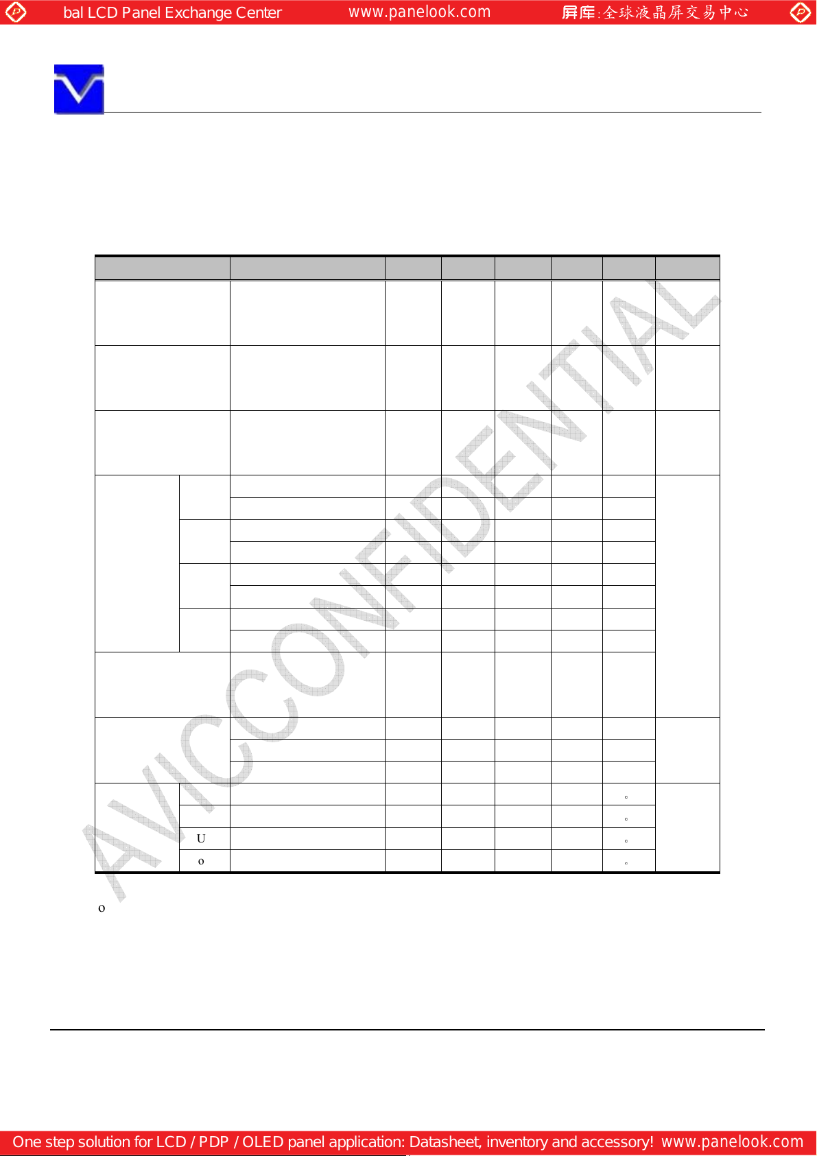
10.1 Optical characteristics
Base on TFT-LCD module TM190MDS01
Parameter Note1 Condition Symbol min. typ. max. Unit Remarks
White at center
Luminance
Contrast ratio
Luminance uniformity
White
Red
Chromaticity
Green
Blue
Color gamut
Response time
Right
Viewing
angle
Left θU=0°, θD=0°, CR≥10 θL - 45 -
Up θR=0°, θL=0°, CR≥10 θU - 25 -
Down
θR=0°, θL=0°, θU=0°,
White/Black at center
θR=0°, θL=0°, θU=0°,
θR=0°, θL=0°, θU=0°,
θR=0°, θL=0°, θU=0°,
At center,against NTSC
θU=0°, θD=0°, CR≥10 θR - 45 -
θR=0°, θL=0°, CR≥10 θD - 45 -
Note1 ,Note2
L 160 200 - cd/ m
θD=0°
CR (420) 600 - - Note3
θD=0°
White
LU - 1.25 (1.33)
θD=0
X coordinate Wx 0.283 0.313 0.343
Y coordinate Wy 0.299 0.329 0.359
X coordinate Rx
Y coordinate Ry
X coordinate Gx
Y coordinate Gy
X coordinate Bx
Y coordinate By
θD=0
White to black Ton - 1.3 (2.6) ms
Black to white Toff - 3.7 (7.4) ms
Ton+ Toff - - 5 (10) ms
C - 72 - %
0.617
0.310
0.253
0.574
0.113
0.037
0.647
0.340
0.283
0.604
0.143
0.067
0.677
0.370
0.313
0.634
0.173
0.097
- Note4
-
-
-
-
-
-
-
-
。
。
。
。
PPPPPPP
2
-
Chromati
city
Note6
Note7
Viewing
angle
Note1: The values in upper table are only initial characteristics, and measured with AVIC backlight unit
Note2: Measurement conditions are as follows.
Ta= 25°C, VDD= 5.0V, IBL= 6.5mArms/lamp, Display mode: WXGA+,
Horizontal cycle=55.56KHz, Vertical cycle=60.0Hz
Optical characteristics are measured at luminance saturation after 30minutes from working the
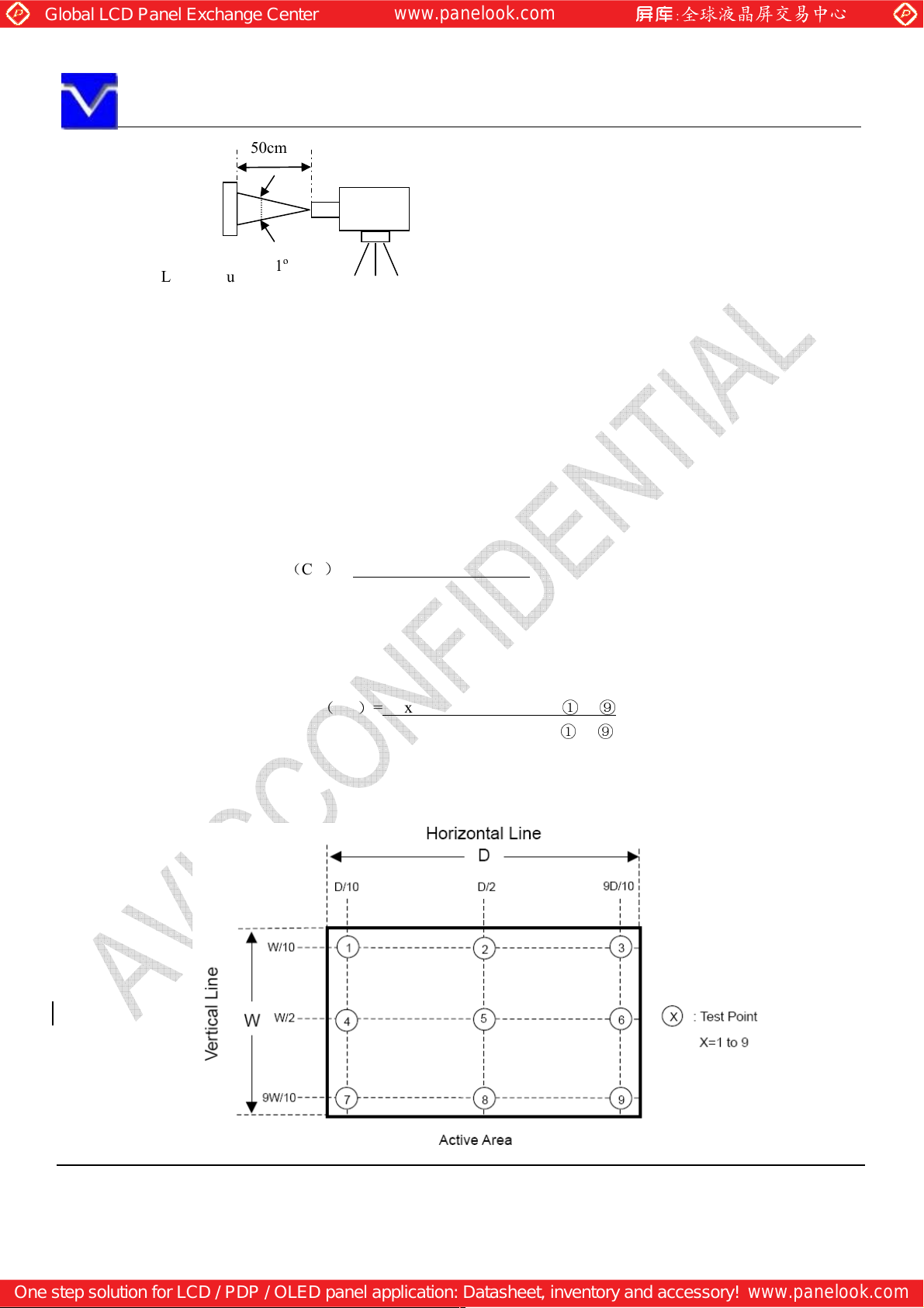
product in the dark room. Also measurement method for luminance is as follows.
The information contained herein is the exclusive property of SHANGHAI AVIC OPTO
permission of SHANGHAI AVIC OPTOELECTRONICS Corporation.
Page 18 of 25
Page 19
ELECTRONICS
Corporation, and shall not be distributed, reproduced, or disclosed in whole or in part without prior written
50cm
(Product)
S
pectroradiometer
(
TOPCON SR
-3)
Global LCD Panel Exchange Center
www.panelook.com
One step solution for LCD / PDP / OLED panel application: Datasheet, inventory and accessory!
www.panelook.com
SHANGHAI AVIC OPTOELECTRONICS Q/S1016-2011
LCD module
Note 3: See“10.2 Definition of contrast ratio”.
Note 4: See“10.3 Definition of luminance uniformity”.
Note 5: CIE 1931 Chromaticity Diagram Standard.
Note 6: Product surface temperature: TopF = 33.0 °C
Note 7: See “10.4 Definition of response time”.
Note 8: See “10.5 Definition of viewing angle”.
1º
Luminance Meter (TOPCON BM-5A)
10.2 Definition of contrast ratio
The contrast ratio is calculated by using the following formula.
Contrast ratio(CR)= Luminance of white screen
Luminance of black screen
10.3 Definition of luminance uniformity
The luminance uniformity is calculated by using the following formula.
Luminance uniformity(LU)=Maximum luminance from ① to ⑨
Minimum luminance from
The luminance is measured at near the 9 points shown below.
171 512 853
128
①①①①
②②②②
①
to ⑨
384
③③③③
640
④④④④
The information contained herein is the exclusive property of SHANGHAI AVIC OPTO
permission of SHANGHAI AVIC OPTOELECTRONICS Corporation.
⑤⑤⑤⑤
Page 19 of 25
Page 20
ELECTRONICS
Corporation, and shall not be distributed, reproduced, or disclosed in whole or in part without prior written
Global LCD Panel Exchange Center
www.panelook.com
One step solution for LCD / PDP / OLED panel application: Datasheet, inventory and accessory!
www.panelook.com
SHANGHAI AVIC OPTOELECTRONICS Q/S1016-2011
10.4 Definition of response times
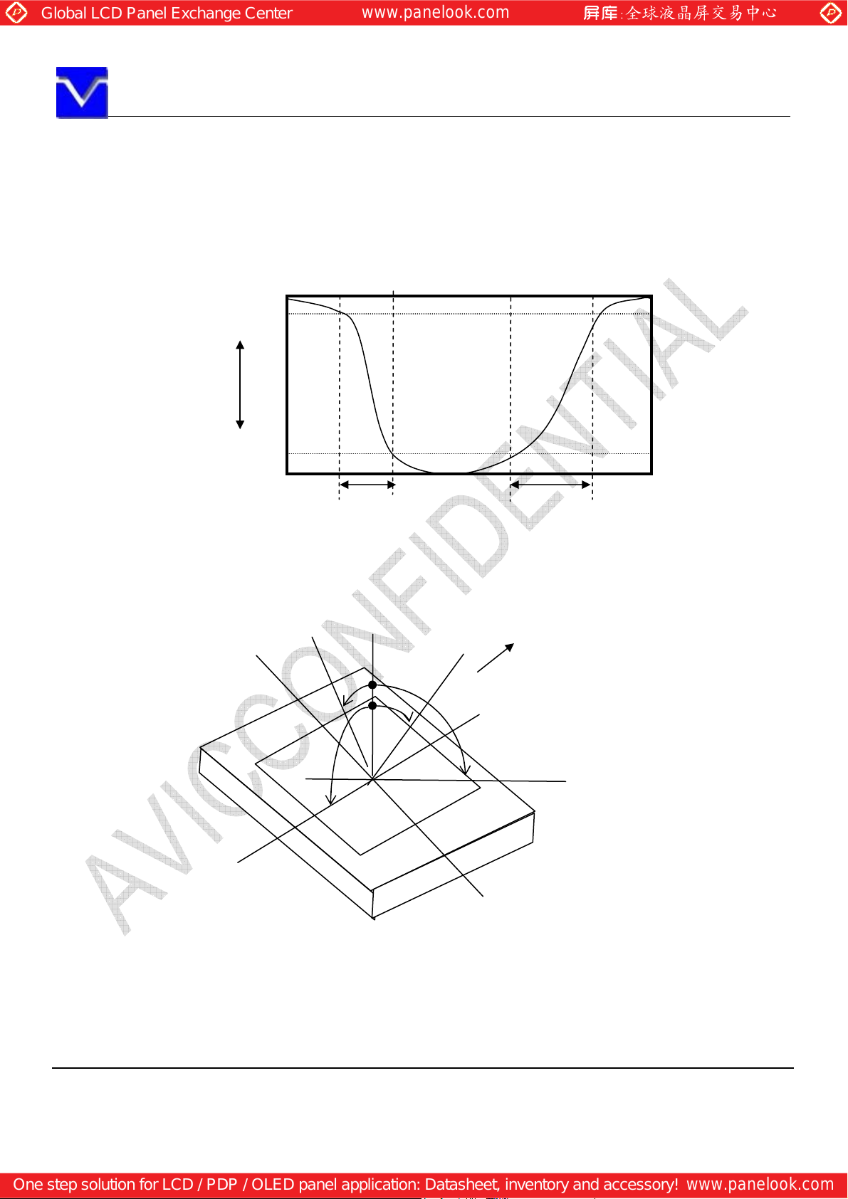
Response time is measured, the luminance changes from “white” to “black”, or “black” to “white” on
the same screen point, by photo-detector. Ton is the time it takes the luminance change from 90% down to
10%. Also Toff is the time it takes the luminance change from 10% up to 90%. (See the following
diagram.)
100%
90%
White
Luminance
Black
10%
0%
Ton Toff
Normal axis (Perpendicular)
10.5 Definition of viewing angles
Left
θD
Lower
12 o’clock
θL
Upper
θU
θR
Right
The information contained herein is the exclusive property of SHANGHAI AVIC OPTO
permission of SHANGHAI AVIC OPTOELECTRONICS Corporation.
Page 20 of 25
Page 21
ELECTRONICS
Corporation, and shall not be distributed, reproduced, or disclosed in whole or in part without prior written
December: C
December: C
Global LCD Panel Exchange Center
www.panelook.com
One step solution for LCD / PDP / OLED panel application: Datasheet, inventory and accessory!
www.panelook.com
SHANGHAI AVIC OPTOELECTRONICS Q/S1016-2011
11. MARKINGS
AVIC will pack products to deliver to customer in accordance with AVIC packing specifications, and will deliver
products to customer in such a state that products will not suffer from damage during transportation .The delivery
conditions are as follows.
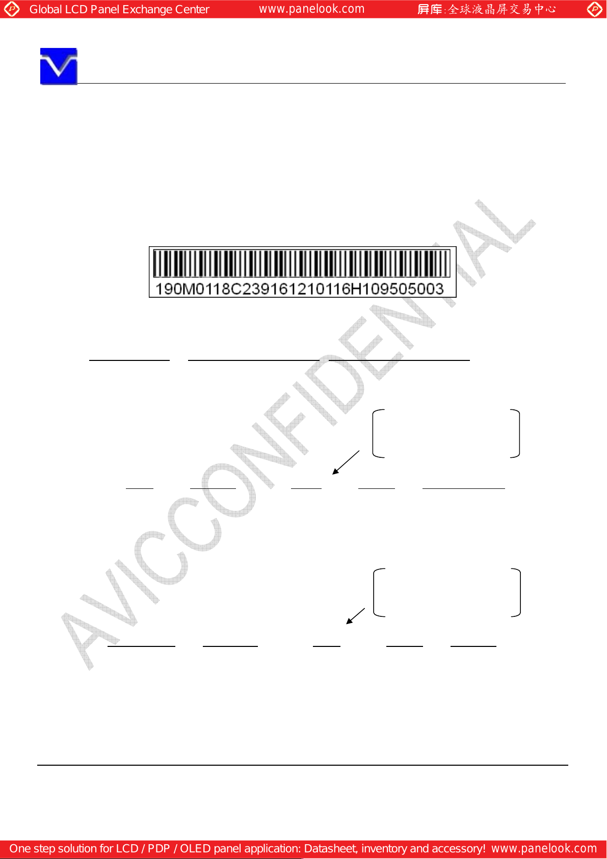
11.1 PRODUCT LABEL
Product label
Open cell barcode:
•Example: 9WX0818C23916121011H6H109505003
190M01 18C239161210 116H109505003
Open cell
Number Code
Cell ID: 18C239161210
8 C 23 9161210
1
S1 Line Manufacturing year
Lot number: 11H6H109505003
Cell ID Lot number
(e.g:A.D2008 is 08.)
Manufacturing
month
1 letter
Jan. to Sep.: Number of month
Manufacturing
day
Jan. to Sep.: Number of month
October: A
November: B
Panel Location
Internal use
October: A
November: B
116H1 09 5 05 003
Internal
use
The information contained herein is the exclusive property of SHANGHAI AVIC OPTO
permission of SHANGHAI AVIC OPTOELECTRONICS Corporation.
Manufacturing year
2 figures of the A.D. end
numbers
(e.g: A.D2009 is 09.)
Manufacturing
month
1 letter
Manufacturing
day
Production
number
Multi-letter
(figure)
Page 21 of 25
Page 22
ELECTRONICS
Corporation, and shall not be distributed, reproduced, or disclosed in whole or in part without prior written
Global LCD Panel Exchange Center
www.panelook.com
One step solution for LCD / PDP / OLED panel application: Datasheet, inventory and accessory!
www.panelook.com
SHANGHAI AVIC OPTOELECTRONICS Q/S1016-2011
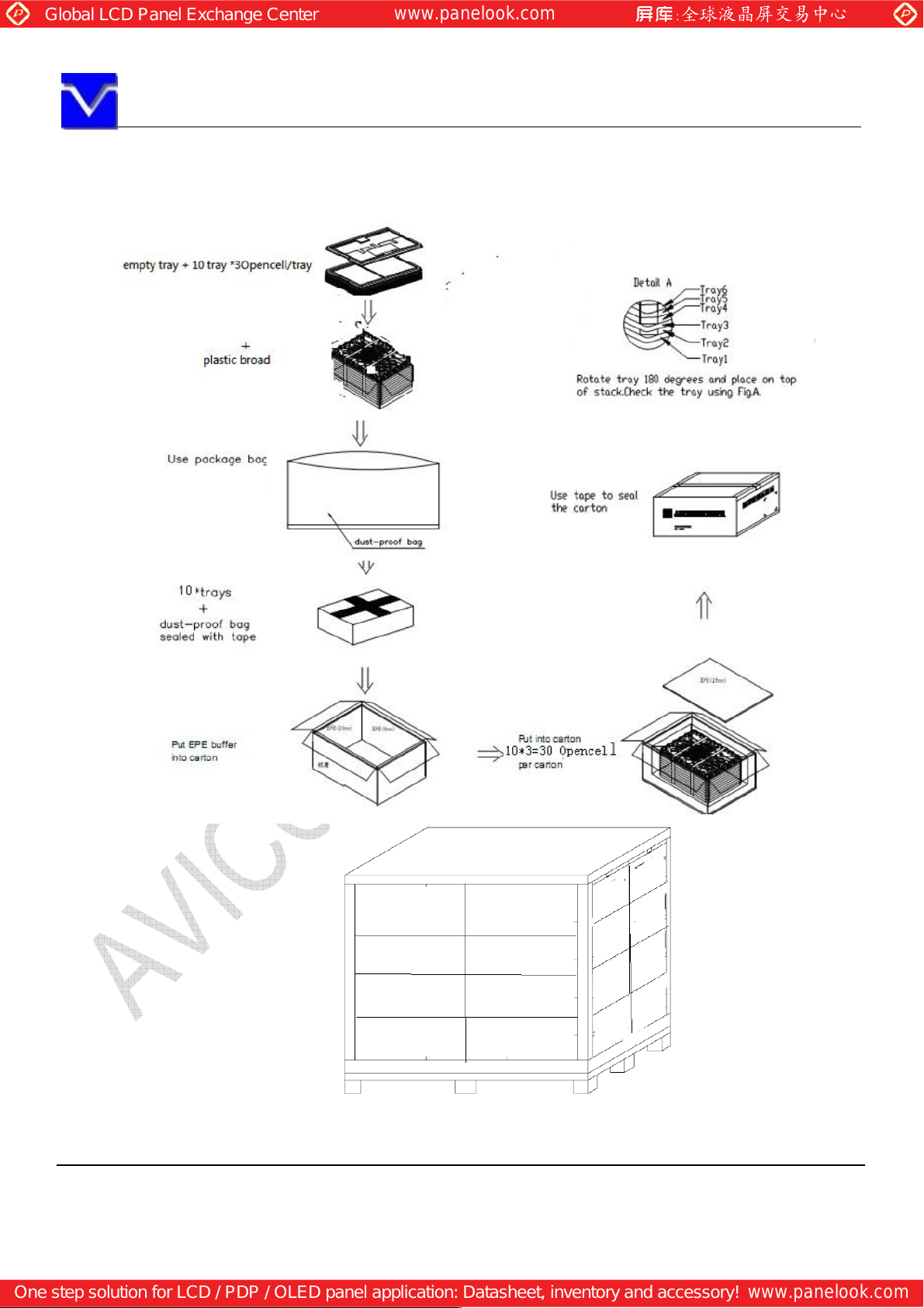
11.2 PACKING
(1) Packing box
5 products are packed up with the maximum in a packing box(See “11.6 OUTLINE FIGURE FOR PACKING
“).
Products are put into a plastic bag for prevention of moisture.
The type name and quality are shown on outside of the packing box, either labeling or printing.
(2)Pallet Packing (See”11.6 OUTLINE FIGURE FOR PACKING “)
①
Packing boxes are tired on a cardboard pallet.
②Cardboard sleeve and top cap are attached to the packing boxes, and then they are fixed by a band.
11.3 INSPECTION RECORD SHEET
Inspection record sheets are included in the packing box with delivery products to customer. It is summarized to a
number of products for pass/fail assessment.
11.4 TRANSPORTATION
The product is transported by vehicle, aircraft or shipment in the state of pallet packing.
11.5 SIZE AND WEIGHT FOR PACKING BOX
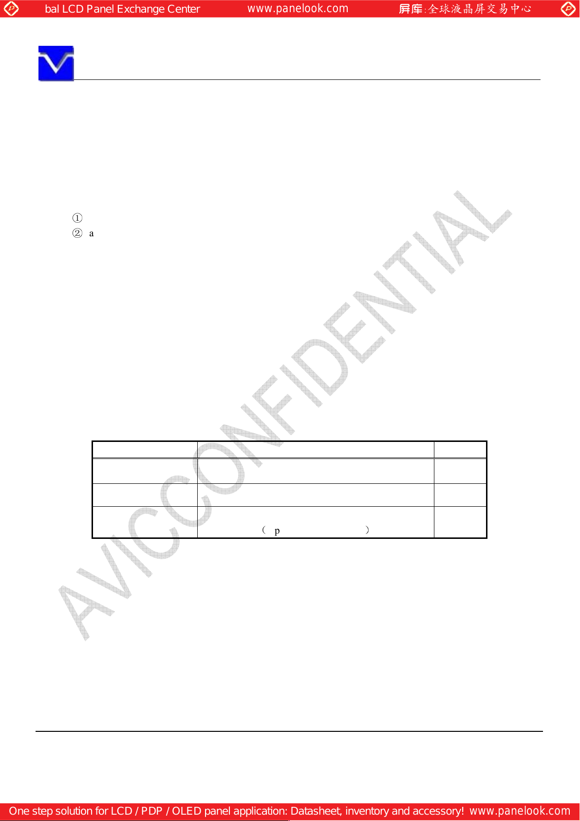
Parameter Packing box Unit
Size 571×459×274(typ.) mm
Weight 0.46(typ.) kg
Total weight
(
typ., with 30 PCS panel)
19.1
kg
The information contained herein is the exclusive property of SHANGHAI AVIC OPTO
permission of SHANGHAI AVIC OPTOELECTRONICS Corporation.
Page 22 of 25
Page 23
ELECTRONICS
Corporation, and shall not be distributed, reproduced, or disclosed in whole or in part without prior written
Global LCD Panel Exchange Center
www.panelook.com
One step solution for LCD / PDP / OLED panel application: Datasheet, inventory and accessory!
www.panelook.com
SHANGHAI AVIC OPTOELECTRONICS Q/S1016-2011
11.6 OUTLINE FIGURE FOR PACKING (For reference)
Packing box and pallet packing
Note: The ways for Packing and Shipping vary from different shipment volume, dependent on specific situations.
The information contained herein is the exclusive property of SHANGHAI AVIC OPTO
permission of SHANGHAI AVIC OPTOELECTRONICS Corporation.
Page 23 of 25
Page 24

ELECTRONICS
Corporation, and shall not be distributed, reproduced, or disclosed in whole or in part without prior written
Global LCD Panel Exchange Center
www.panelook.com
One step solution for LCD / PDP / OLED panel application: Datasheet, inventory and accessory!
www.panelook.com
SHANGHAI AVIC OPTOELECTRONICS Q/S1016-2011
12. PRECAUTIONS
12.1 ASSEMBLY AND HANDLING PRECAUTIONS
1) Take the measures of electrostatic discharge such as earth band, ionic shower and so on, when customer deals with
the product, because products may be damaged by electrostatic.
2) Do not operate or store in high temperature, high humidity, dewdrop atmosphere or corrosive gases. Keep the
product in antistatic pouch in room temperature, because of avoidance for dusts and sunlight, if customer stores
the product.
3) In order to prevent dew condensation occurring by temperature difference, the product packing box must be
opened after leave under the environment of an unpacking room temperature enough. Because a situation of dew
condensation occurring is changed by the environment temperature and humidity, evaluate the leaving time
sufficiently. (Recommendation leaving time: 6 hour or more with packing state)
4) This product is not designed as radiation hardened.
5) To assemble backlight or install module into user’s system, it should be in clean working areas. The dust and oil
may cause electrical short or worsen the polarizer.
6) If the liquid crystal material leaks from the panel, it should be kept away from the eyes or mouth. In case of
contact with hands, skin or clothes, it has to be washed away thoroughly with soap.
7) It is dangerous that moisture come into or contacted the product, because moisture may damage the product when
it is operating.
8) High temperature or humidity may reduce the performance of module. Please store this product within the
specified storage condition.
9) When ambient temperature is lower than 10 may reduce the display quality. For example, the response time will
become slowly.
10) Do not apply rough force such as bending or twisting to the product during assembly.
11) It’s not permitted to have pressure or impulse on the module because the LCD panel will be damaged.
12) Do not pull the I/F connector in or out while the module is operating.
13) After the product’s end of life, it is not harmful in case of normal operation and storage.
℃
12.2 OTHER
All GND and VCC terminals should be used without a non-connected line.
The following items are neither defects nor failures.
1) Response time, luminance and color may be changed by ambient temperature.
2) The LCD may be seemed luminance non-uniformity, flicker, vertical seam or small spot by display patterns.
3) The interference noise of input signal frequency for this product and luminance control frequency of customer’s
backlight inverter may appear on a display. Set up luminance control frequency of backlight inverter so that the
interference noise does not appear.
The information contained herein is the exclusive property of SHANGHAI AVIC OPTO
permission of SHANGHAI AVIC OPTOELECTRONICS Corporation.
Page 24 of 25
Page 25
ELECTRONICS
Corporation, and shall not be distributed, reproduced, or disclosed in whole or in part without prior written
Global LCD Panel Exchange Center
www.panelook.com
One step solution for LCD / PDP / OLED panel application: Datasheet, inventory and accessory!
www.panelook.com
SHANGHAI AVIC OPTOELECTRONICS Q/S1016-2011
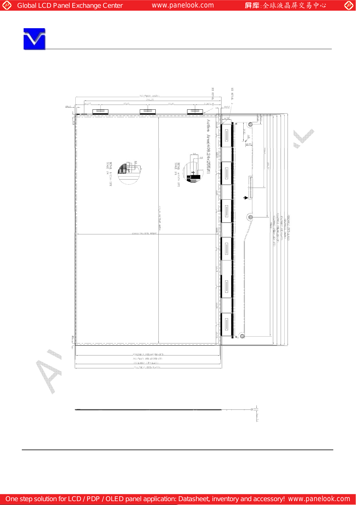
13. OUTDRAWING
Pin1
The information contained herein is the exclusive property of SHANGHAI AVIC OPTO
permission of SHANGHAI AVIC OPTOELECTRONICS Corporation.
Page 25 of 25
 Loading...