

Page 1
SHANGHAI AVIC OPTOELECTRONICS Q/S1021-2011
MODEL NO. : TM121SDS01
ISSUED DATE: 2011/09/08
VERSION : 1.1
■Preliminary Specification
□Final Product Specification
Customer :
Approved by Notes
SHANGHAI AVIC Confirmed :
Prepared by Checked by Approved by
Hyman Chen _ ANFERNEE DU
This technical specification is subjected to change without notice
The information contained herein is the exclusive property of SHANGHAI AVIC OPTOELECTRONICS
Corporation, and shall not be distributed, reproduced, or disclosed in whole or in part without prior written
permission of SHANGHAI AVIC OPTOELECTRONICS Corporation.
Page 1 of 32
Page 2

SHANGHAI AVIC OPTOELECTRONICS Q/S1021-2011
TABLE OF CONTENTS
TABLE OF CONTENTS ............................................................................................................................................... 2
RECORD OF REVISION .......................................................................................................................................... 3
1. OUTLINE .............................................................................................................................................................. 4
1.1 STRUCTURE AND PRINCIPLE..................................................................................................................... 4
1.2 APPLICATIONS .............................................................................................................................................. 4
1.3 FEATURES .................................................................................................................................................... 4
2. GENERAL SPECIFICATIONS .............................................................................................................................. 5
3. ABSOLUTE MAXIMUM RATINGS ....................................................................................................................... 6
4. BLOCK DIAGRAM ............................................................................................................................................... 7
5. MECHANICAL SPECIFICATIONS ....................................................................................................................... 8
6. ELECTRICAL CHARACTERISTICS .................................................................................................................... 9
6.1 DRIVING FOR LCD ....................................................................................................................................... 9
6.2 DRIVING FOR BACKLIGHT ........................................................................................................................ 10
7. CONNECTIONS AND FUNCTIONS FOR INTERFACE PINS ............................................................................ 11
7.1 LVDS ............................................................................................................................................................ 11
7.2 BACKLIGHT ................................................................................................................................................. 12
7.3 POSITION OF PLUGS AND A SOCKET ..................................................................................................... 12
7.4 CONNECTION BETWEEN RECEIVER AND TRANSMITTER FOR LVDS ................................................. 13
8. DISPLAY COLORS AND INPUT DATA SIGNALS .............................................................................................. 14
9. INTERFACE TIMING .......................................................................................................................................... 15
9.1 TIMING CHARACTERISTICS ...................................................................................................................... 15
9.2 INPUT SIGNAL TIMING CHART ............................................................................................................... 16
9.3 PIXEL DATA ALIGNMENT OF DISPLAY IMAGE ...................................................................................... 17
9.4. POWER SUPPLY VOLTAGE SEQUENCE ................................................................................................. 18
10. OPTICS ............................................................................................................................................................ 20
11. MARKINGS ...................................................................................................................................................... 24
11.1 PRODUCT LABEL ...................................................................................................................................... 24
11.2 INDICATION LOCATIONS ......................................................................................................................... 25
12. PACKING, TRANSPORTATION AND DELIVERY ............................................................................................ 26
13. PRECAUTIONS ............................................................................................................................................... 28
14.OUTDRAWING ................................................................................................................................................. 31
The information contained herein is the exclusive property of SHANGHAI AVIC OPTOELECTRONICS
Corporation, and shall not be distributed, reproduced, or disclosed in whole or in part without prior written
permission of SHANGHAI AVIC OPTOELECTRONICS Corporation.
Page 2 of 32
Page 3
SHANGHAI AVIC OPTOELECTRONICS Q/S1021-2011
RECORD OF REVISION
Rev Issued Date Description Editor
1.0 2011-6-16 Preliminary Release Wei Zhang
1.1 2011-8-22 Change the INTERFACE PINS Hyman Chen
The information contained herein is the exclusive property of SHANGHAI AVIC OPTOELECTRONICS
Corporation, and shall not be distributed, reproduced, or disclosed in whole or in part without prior written
permission of SHANGHAI AVIC OPTOELECTRONICS Corporation.
Page 3 of 32
Page 4

SHANGHAI AVIC OPTOELECTRONICS Q/S1021-2011
1. OUTLINE
1.1 STRUCTURE AND PRINCIPLE
TM121SDS01 module is composed of the amorphous silicon thin film transistor liquid crystal display
(a-Si TFT LCD) panel structure with driver LSIs for driving the TFT (Thin Film Transistor) array and a acklight.
The a-Si TFT LCD panel structure is injected liquid crystal material into a narrow gap between the TFT array
glass substrate and a color-filter glass substrate.
Color (Red, Green, Blue) data signals from a host system (e.g. PC, signal generator, etc.) are
modulated into best form for active matrix system by a signal processing board, and sent to the driver LSIs
which drive the individual TFT arrays. The TFT array as an electro-optical switch regulates the amount of
transmitted light from the backlight assembly, when it is controlled by data signals. Color images are created
by regulating the amount of transmitted light through the TFT array of red, green and blue dots.
1.2 APPLICATIONS
• Monitor for industrial display
1.3 FEATURES
• a-Si TFT active matrix
• LVDS interface
• R.G.B input 8bit, 16.2 millions colors (6bit+FRC)
• Resolution SVGA (800× 600 pixels)
• Wide viewing angle 80°/80° (L/R); 65°/75° (U/D)
• Contrast ratio 700 :1
• Module size 279.0 (H) ×209.0 (V) ×9.0 (D) mm
• Fast response time (Ton+ Toff= 35 ms)
• Color gamut (55%)
• Edge light type backlight (White-LED)
• Inverter less
• RoHS compliance
• TCO 5.0 compliance
The information contained herein is the exclusive property of SHANGHAI AVIC OPTOELECTRONICS
Corporation, and shall not be distributed, reproduced, or disclosed in whole or in part without prior written
permission of SHANGHAI AVIC OPTOELECTRONICS Corporation.
Page 4 of 32
Page 5
SHANGHAI AVIC OPTOELECTRONICS Q/S1021-2011
2. GENERAL SPECIFICATIONS
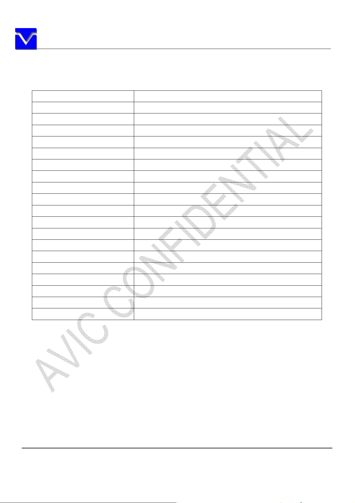
Display area 246.0 (H) × 184.5 (V) mm (typ.)
Diagonal size of display 30.7 cm (12.1 inches)
Drive system a-Si TFT active matrix
Display color 16.2 M colors (6bit+FRC)
Pixel 800 (H) × 600(V) pixels
Pixel arrangement
RGB vertical stripe
Pixel pitch 0.3075 (H) × 0.3075 (V) mm
Module size
279.0 (H) ×209.0 (V) ×9.0 (D) mm
Weight TBD
Contrast ratio
Viewing angle
Color gamut
Response time
Luminance
Transmissive Mode
Surface Treatment
Signal system
700 :1 (typ.)
160°/ 135° (typ.)
55 % (typ.)
35 ms (typ.)
2
450 cd/m
(typ.)
Normally White
Anti Glare
LVDS 1port
Power supply voltage LCD panel signal processing board: 3.3V
Backlight White-LED
Power consumption
TBD
The information contained herein is the exclusive property of SHANGHAI AVIC OPTOELECTRONICS
Corporation, and shall not be distributed, reproduced, or disclosed in whole or in part without prior written
permission of SHANGHAI AVIC OPTOELECTRONICS Corporation.
Page 5 of 32
Page 6
SHANGHAI AVIC OPTOELECTRONICS Q/S1021-2011
3. ABSOLUTE MAXIMUM RATINGS
Parameter Symbol Rating Unit Remarks
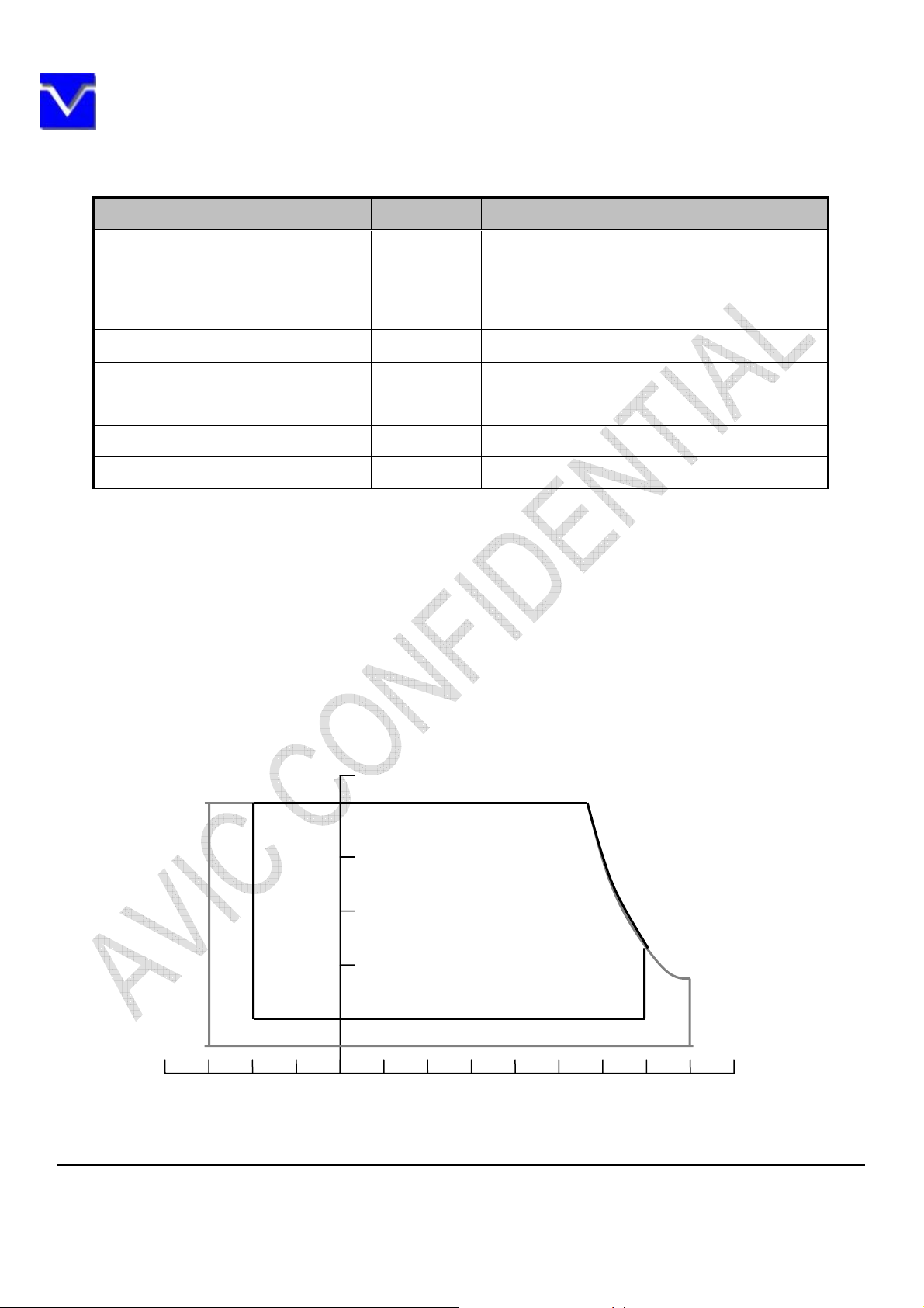
Power Supply Voltage -0.3 ~ +6.0 V Ta = 25°C Ta = 25°C
Input voltage for signals Vi -0.3 ~ +3.3 V Ta = 25°C
Light bar peak forward current IF 150 mArms Note 3
Storage temperature Tst -30 ~ +80 °C Note 4
Operating temperature Top -20 ~ +70 °C Note 4, 5
Absolute humidity AH 70 g/m3 Ta > 50°C
Operating altitude - 4,850 m -20°C Ta 70°C
Storage altitude - 13,600 m -30°C Ta 80°C
Note1: Display signals are DA0+/-, DA1+/-, DA2+/-, DA3+/-, CKA+/-, DB0+/-, DB1+/-, DB2+/-, DB3+/-,
and CKB+/-.
Note2: Function signal is MSL.
Note3: Temperature and relative humidity range is shown in the figure below.
(a) 90%RH Max. (Ta 40°C)
(b) Wet-bulb temperature should be39°C Max. (Ta> 40°C)
(c) No condensation.
Note4: The temperature of panel display surface area should be -20°C Min and 80°C Max.
Temperature (℃)
-40 -20 0 20 40 60 80
Relative Humidity(%RH)
80
60
Operating Range
40
20
5
Storage Range
The information contained herein is the exclusive property of SHANGHAI AVIC OPTOELECTRONICS
Corporation, and shall not be distributed, reproduced, or disclosed in whole or in part without prior written
permission of SHANGHAI AVIC OPTOELECTRONICS Corporation.
Page 6 of 32
Page 7

SHANGHAI AVIC OPTOELECTRONICS Q/S1021-2011
4. BLOCK DIAGRAM
LCD MODULE I/F
LVDS Receiver
Timing Controller
Source Driver
Gate Driver
Power
12V, On/Off
LCD Panel
H:800× 3(R,G,B)
V: 600
Edge side backlight
LED Driver
DA0+
DA0-
DA1+
DA1-
DA2+
DA2-
CKA+
CKA-
DA3+
DA3-
DB0+
DB0-
DB1+
DB1-
DB2+
DB2-
CKB+
CKA-
DB3+
DB3-
100Ω
100Ω
100Ω
100Ω
100Ω
100Ω
100Ω
100Ω
100Ω
100Ω
VDD
DC/DC
`
FG
GND
Note: System ground (GND), FG (Frame ground) in the product should be connected together in
customer equipment.
The information contained herein is the exclusive property of SHANGHAI AVIC OPTOELECTRONICS
Corporation, and shall not be distributed, reproduced, or disclosed in whole or in part without prior written
permission of SHANGHAI AVIC OPTOELECTRONICS Corporation.
Page 7 of 32
Page 8
SHANGHAI AVIC OPTOELECTRONICS Q/S1021-2011
5. MECHANICAL SPECIFICATIONS
Parameter Specification Unit
Module size 279.0± 0.5 (W) × 209.0 ± 0.5 (H) × 9.0(D) mm
Display area
Weight TBD g
246.0(H) × 184.5(V) mm (typ.),
[30.75 cm (12.1 inches)]
mm
The information contained herein is the exclusive property of SHANGHAI AVIC OPTOELECTRONICS
Corporation, and shall not be distributed, reproduced, or disclosed in whole or in part without prior written
permission of SHANGHAI AVIC OPTOELECTRONICS Corporation.
Page 8 of 32
Page 9
SHANGHAI AVIC OPTOELECTRONICS Q/S1021-2011
6. ELECTRICAL CHARACTERISTICS
6.1 DRIVING FOR LCD
Parameter Symbol min. typ. max. Unit Remarks
Power supply voltage VDD 3.0 3.3 3.6 V -
Power supply current IDD - -
325
Note 1
Permissible ripple voltage VRP - - 100 mV VDD
Differential input voltage
Differential input threshold
voltage for LVDS receiver
Low VTL -100 - - mV
High VTH - - 100 mV
Input voltage width for LVDS
receiver
︱Vid︱
Vi 0 - 2.4 V -
250 450 mV
Terminating resistor RT - 100 - -
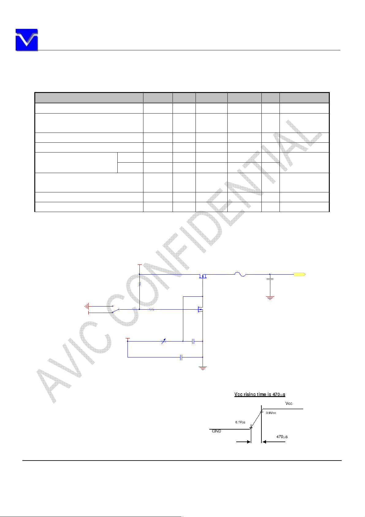
Rush current I
- - 1.5 A Note3
rush
Note 1: All black pattern
Note 2: Common mode voltage for LVDS receiver
Note 3: Measurement Conditions:
5V
Q1
R1
47K
MOSFET- N
F1
Fuse ( 2A)
mA at VDD = 3.3V
VCM = 1.25V
Note2
C1
Cap
1uF/16V
VDD
GND
S2
1
2
5V
3
SW- SPD T
12V
R2
1K
R3
20K
C3
Cap
10uF/16V
C2
Cap
1uF/16V
Q2
MOSFE T- N
GND
GND
The information contained herein is the exclusive property of SHANGHAI AVIC OPTOELECTRONICS
Corporation, and shall not be distributed, reproduced, or disclosed in whole or in part without prior written
permission of SHANGHAI AVIC OPTOELECTRONICS Corporation.
Page 9 of 32
Page 10
SHANGHAI AVIC OPTOELECTRONICS Q/S1021-2011
6.2 DRIVING FOR BACKLIGHT
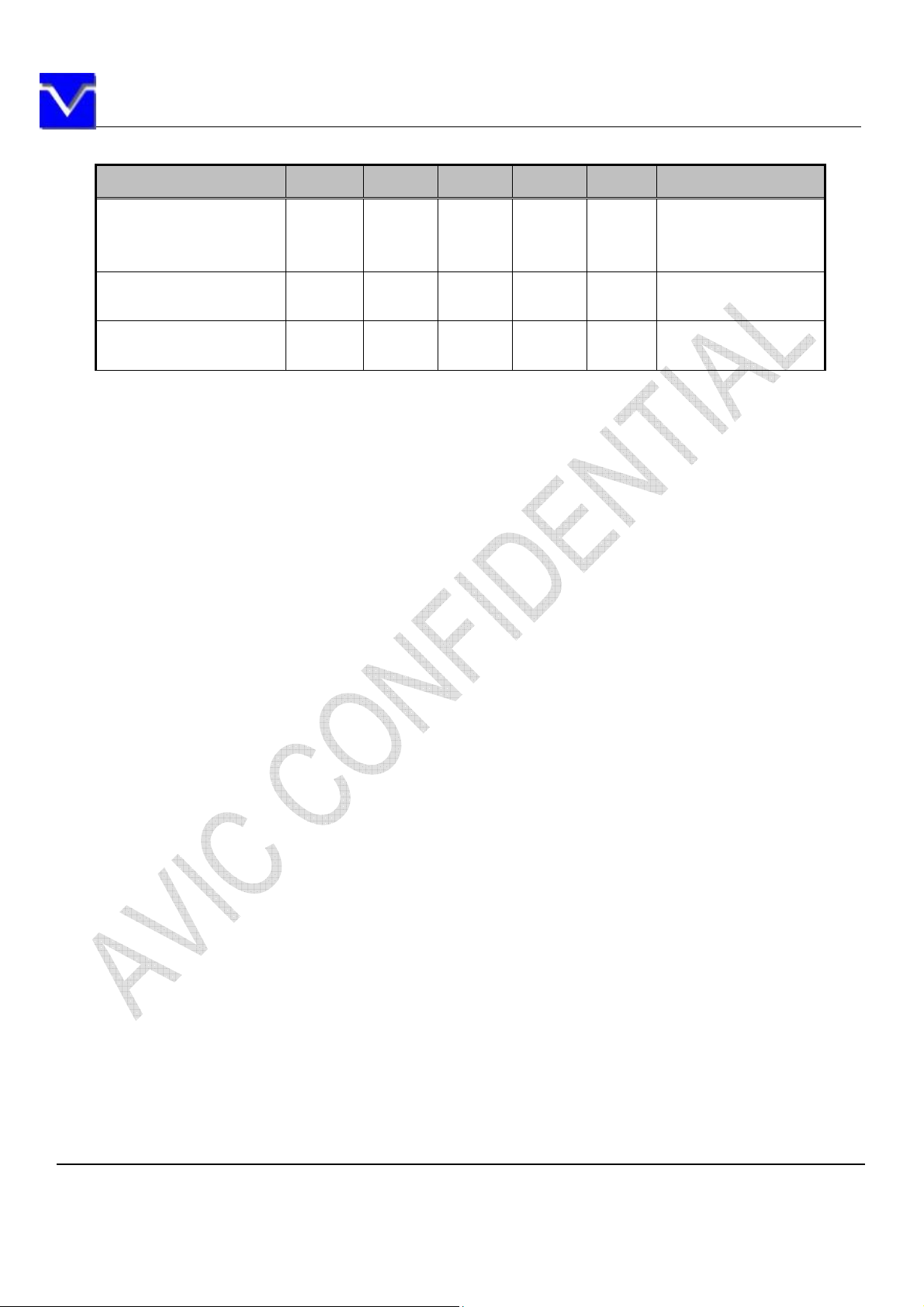
(Ta=25°C) Note1
Parameter Symbol min. typ. max. Unit Remarks
Light bar operation
voltage
(for reference)
Light bar
operation current (pin)
Light bar
operating lifetime
V
25 - 33 Vrms
LED
I
- 80 - mArms Note1
LED
Hr 50000 - - Hour I
Operating with fixed
driving current
=80mA,Note3
LED
Note1: The backlight of this product is made up of 1 light bar, LED to be 3020, 20pieces, 10 serials and 2
parallels.
Note2: The light bar can work normally if the PWM dimming ratio range is from 0% to 100% and the
operation current is 80mA.
Note3: The operating lifetime is mean time to half-luminance. In case the product works under room
temperature environment.
The information contained herein is the exclusive property of SHANGHAI AVIC OPTOELECTRONICS
Corporation, and shall not be distributed, reproduced, or disclosed in whole or in part without prior written
permission of SHANGHAI AVIC OPTOELECTRONICS Corporation.
Page 10 of 32
Page 11

SHANGHAI AVIC OPTOELECTRONICS Q/S1021-2011
7. CONNECTIONS AND FUNCTIONS FOR INTERFACE PINS
7.1 LVDS
CN1: MSB240420HE (Produced by STM) or equivalent.
Pin Name Description
1 VCC 3.3V Power Supply
2 VCC 3.3V Power Supply
3 GND Ground
6-8Bit SEL Select 6 or 8 Bits LVDS Input (VCC:8Bits ; GND/NC: 6Bits)
4
RIN0- Negative(-) LVDS differential data input
5
RIN0+ Positive(+) LVDS differential data input
6
7 GND Ground
RIN1- Negative(-) LVDS differential data input
8
RIN1+ Positive(+) LVDS differential data input
9
10 GND Ground
RIN2- Negative(-) LVDS differential data input
11
RIN2+ Positive(+) LVDS differential data input
12
13 GND Ground
CLKIN- Clock Signal(-)
14
CLKIN+ Clock Signal(+)
15
16 GND Ground
RIN3-
17
RIN3+
18
REVERSE
19
NC/GND Test Function Pin(Do not set this pin to High)
20
Negative(-) LVDS differential data input
(Used for 8Bits LVDS Input; NC for 6Bits)
Positive(+) LVDS differential data input
(Used for 8Bits LVDS Input; NC for 6Bits)
Display Reversed Function
(VCC: Display Reverse; GND/NC: Normal Display)
The information contained herein is the exclusive property of SHANGHAI AVIC OPTOELECTRONICS
Corporation, and shall not be distributed, reproduced, or disclosed in whole or in part without prior written
permission of SHANGHAI AVIC OPTOELECTRONICS Corporation.
Page 11 of 32
Page 12
SHANGHAI AVIC OPTOELECTRONICS Q/S1021-2011
5
7.2 BACKLIGHT
CN2: MSB24038P5 (Produced by STM) or equivalent.
Pin
1 Vcc 12V
2 GND GND
3 Enable 5V-On / 0V-Off
4 Dimming PWM Dimming
5 NC NC
Symbol
PWM Dimming:
Parameter Symbol min. typ. max. Unit
PWM Input
Threshold Voltage
PWM Input Frequency 1/T
Logic-High V
Logic-Low V
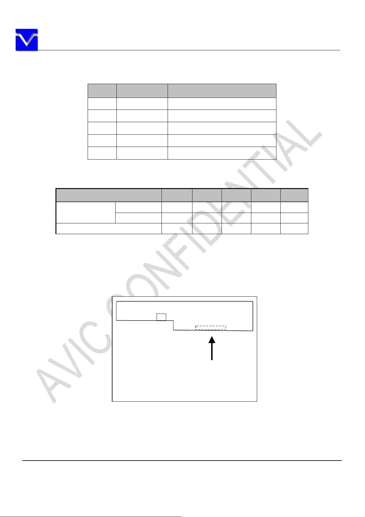
7.3 POSITION OF PLUGS AND A SOCKET
Signal Name
1.2 - - V
PWMH
- - 0.4 V
PWML
PWM
100 200 10K Hz
CN2
20 CN1 1
1
Insert direction
The information contained herein is the exclusive property of SHANGHAI AVIC OPTOELECTRONICS
Corporation, and shall not be distributed, reproduced, or disclosed in whole or in part without prior written
permission of SHANGHAI AVIC OPTOELECTRONICS Corporation.
Page 12 of 32
Page 13
SHANGHAI AVIC OPTOELECTRONICS Q/S1021-2011
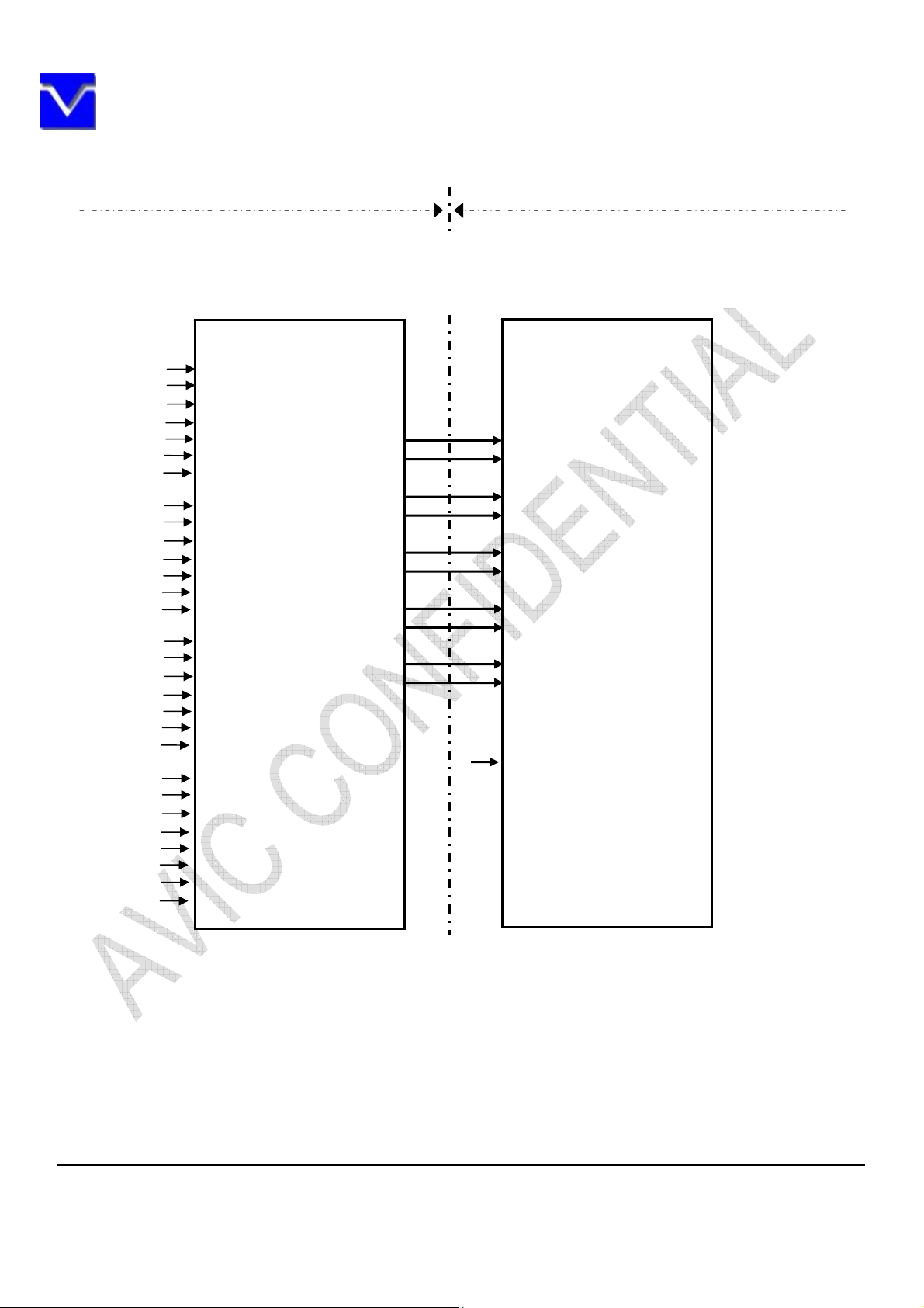
7.4 CONNECTION BETWEEN RECEIVER AND TRANSMITTER FOR LVDS
LVDS Transmitter
TM121SDS01 CN1
D0D0+
D1D1+
D2D2+
CLKCLK+
D3D3+
6-8Bit SEL
High or Low
High or Low
R0
R1
R2
R3
R4
R5
G0
G1
G2
G3
G4
G5
B0
B1
B2
B3
B4
B5
DE
R6
R7
G6
G7
B6
B7
RSVD
CLK
TXIN0
TXIN1
TXIN2
TXIN3
TXIN4
TXIN6
TXIN7
TXIN8
TXIN9
TXIN12
TXIN13
TXIN14
TXIN15
TXIN18
TXIN19
TXIN20
TXIN21
TXIN22
TXIN24
TXIN25
TXIN26
TXIN27
TXIN5
TXIN10
TXIN11
TXIN16
TXIN18
TXIN23
CLK IN
Note1: The lowest bit (RA0, GA0, BA0, RB0, GB0, BB0), the most upper bit (RA7, GA7, BA7, RB7, GB7,
BB7)
Note2:Connecting cable between LCD panel’s connector and transmitter should use 100 twisted line.
Note3: If only Hsync and Vsync, the product don’t work. Make sure DE signal has been input.
The information contained herein is the exclusive property of SHANGHAI AVIC OPTOELECTRONICS
Corporation, and shall not be distributed, reproduced, or disclosed in whole or in part without prior written
permission of SHANGHAI AVIC OPTOELECTRONICS Corporation.
Page 13 of 32
Page 14
SHANGHAI AVIC OPTOELECTRONICS Q/S1021-2011
8. DISPLAY COLORS AND INPUT DATA SIGNALS
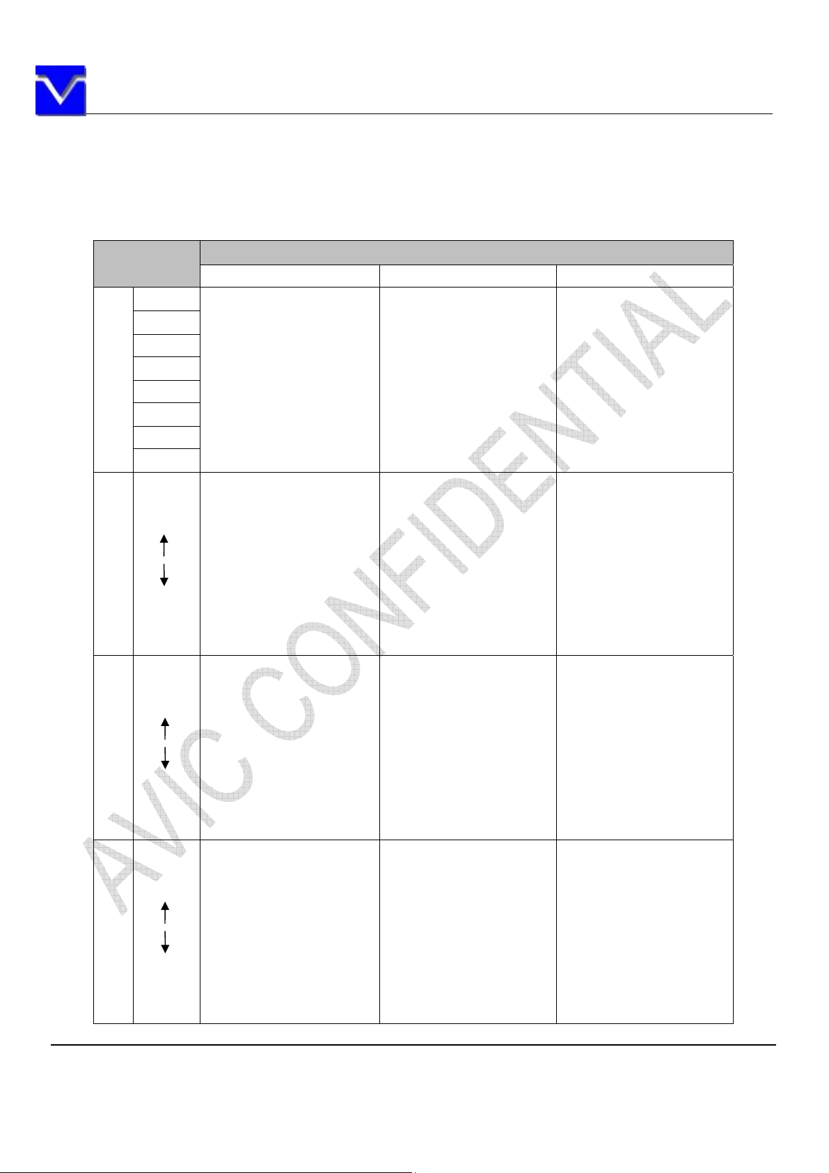
This product can display in equivalent to 16.2M colors in 256 scales. Also the relation between
display colors and input data signals is as the following table.
Display colors
Black 0 0 0 0 0 0 000000000000 0 0 0 0 00
Blue 0 0 0 0 0 0 000000000011 1 1 1 1 11
Red 1 1 1 1 1 1 110000000000 0 0 0 0 00
Magenta 1 1 1 1 1 1 110000000011 1 1 1 1 11
Green 0 0 0 0 0 0 001111111100 0 0 0 0 00
Basic Color
Cyan 0 0 0 0 0 0 001111111111 1 1 1 1 11
Yellow 1 1 1 1 1 1 111111111100 0 0 0 0 00
White 1 1 1 1 1 1 111111111111 1 1 1 1 11
Black
Dark
Bright
Red grayscale
Red
Black
Dark
Bright
Green grayscale
Green
Black
Dark
Bright
Blue grayscale
Blue
R7 R6 R5 R4 R3 R2 R1 R0 G7 G6 G5 G4 G3 G2 G1 G0 B7 B6 B5 B4 B3 B2 B1 B0
0 0 0 0 0 0 000000000000 0 0 0 0 00
0 0 0 0 0 0 010000000000 0 0 0 0 00
0 0 0 0 0 0 100000000000 0 0 0 0 00
1 1 1 1 1 1 010000000000 0 0 0 0 00
1 1 1 1 1 1 100000000000 0 0 0 0 00
1 1 1 1 1 1 110000000000 0 0 0 0 00
0 0 0 0 0 0 000000000000 0 0 0 0 00
0 0 0 0 0 0 000000000100 0 0 0 0 00
0 0 0 0 0 0 000000001000 0 0 0 0 00
0 0 0 0 0 0 001111110100 0 0 0 0 00
0 0 0 0 0 0 001111111000 0 0 0 0 00
0 0 0 0 0 0 001111111100 0 0 0 0 00
0 0 0 0 0 0 000000000000 0 0 0 0 00
0 0 0 0 0 0 000000000000 0 0 0 0 01
0 0 0 0 0 0 000000000000 0 0 0 0 10
0 0 0 0 0 0 000000000011 1 1 1 1 01
0 0 0 0 0 0 000000000011 1 1 1 1 10
0 0 0 0 0 0 000000000011 1 1 1 1 11
: : :
: : :
: : :
: : :
: : :
: : :
Data signal (0:Low level,1:High Level)
The information contained herein is the exclusive property of SHANGHAI AVIC OPTOELECTRONICS
Corporation, and shall not be distributed, reproduced, or disclosed in whole or in part without prior written
permission of SHANGHAI AVIC OPTOELECTRONICS Corporation.
Page 14 of 32
Page 15
SHANGHAI AVIC OPTOELECTRONICS Q/S1021-2011
9. INTERFACE TIMING
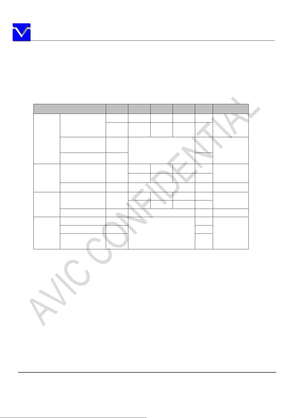
9.1 TIMING CHARACTERISTICS
Parameter Symbol min. typ. max. Unit Remarks
1/tc 33.16 39.80 49.74 MHz
Clock
Horizonta
l signals
Vertical
signals
DE/Data
Frequency
Rise time, Fall
time
Duty - -
Cycle th
Display period thd 800 CLK -
Cycle tv
Display period tvd 600 H -
Setup time -
Hold time - ns
Rise time, Fall
time
tc 30.16 25.13 20.10 ns
-
- ns
Note1: See the data sheet of LVDS transmitter.
Refer to the timing
characteristics of LVDS
transmitter
14.8 18.0 26.5 µs
920 1056 1240 CL K
13.3 16.67 20 m s
608 628 650 H
Refer to the timing
characteristics of LVDS
transmitter
ns
ns
LVDS
transmitter
input
Note 1
55.5kHz(typ.)
60.0Hz(typ.)
Note 1
The information contained herein is the exclusive property of SHANGHAI AVIC OPTOELECTRONICS
Corporation, and shall not be distributed, reproduced, or disclosed in whole or in part without prior written
permission of SHANGHAI AVIC OPTOELECTRONICS Corporation.
Page 15 of 32
Page 16
SHANGHAI AVIC OPTOELECTRONICS Q/S1021-2011
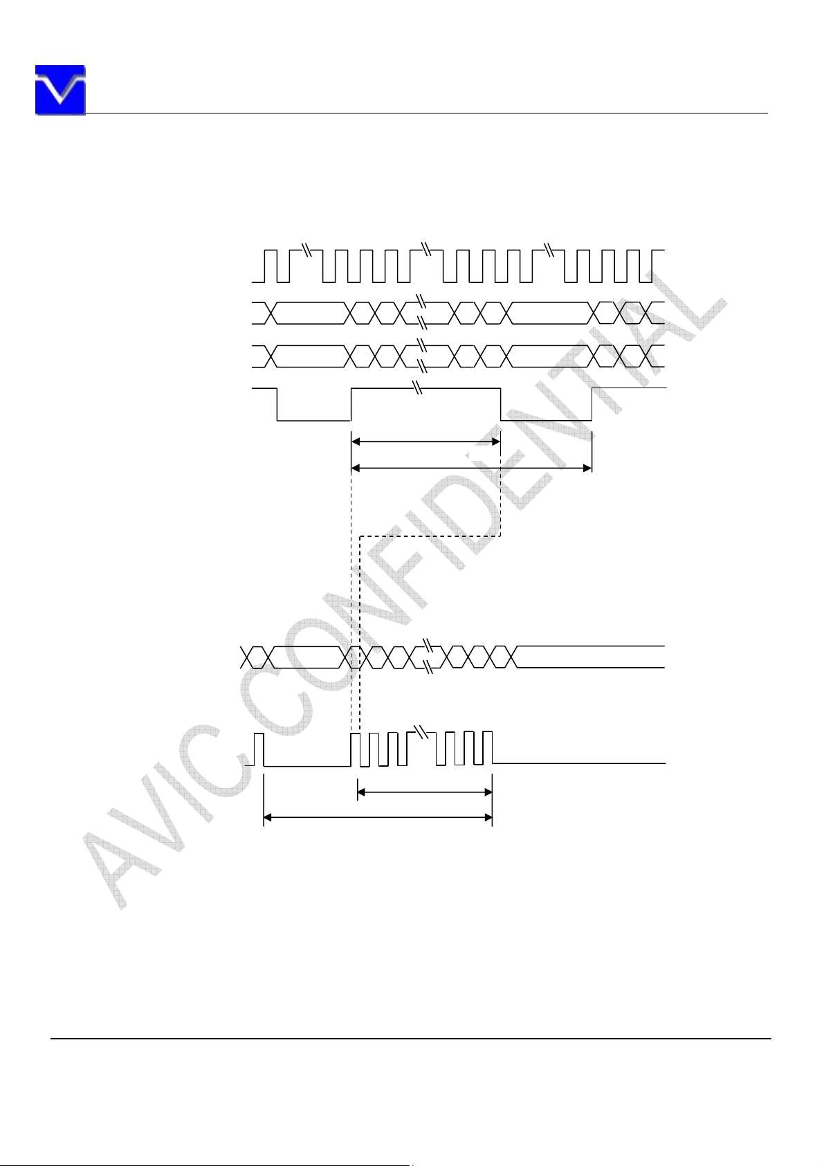
9.2 INPUT SIGNAL TIMING CHART
Horizontal timing
CLK
DATA(A) note1 Invalid 1 3 797 799 Invalid
DATA(B)
Invalid 2 4 798 800 Invalid
DE
thd
Vertical timing
DATA(A),(B) Invalid Invalid
1 2 599 600
DE
tv
tvd
Note 1:
DATA(A)=RA0-RA7,GA0-GA7,BA0-BA7
DATA(B)=RB0-RB7,GB0-GB7,BB0-BB7
The information contained herein is the exclusive property of SHANGHAI AVIC OPTOELECTRONICS
Corporation, and shall not be distributed, reproduced, or disclosed in whole or in part without prior written
permission of SHANGHAI AVIC OPTOELECTRONICS Corporation.
Page 16 of 32
Page 17
SHANGHAI AVIC OPTOELECTRONICS Q/S1021-2011
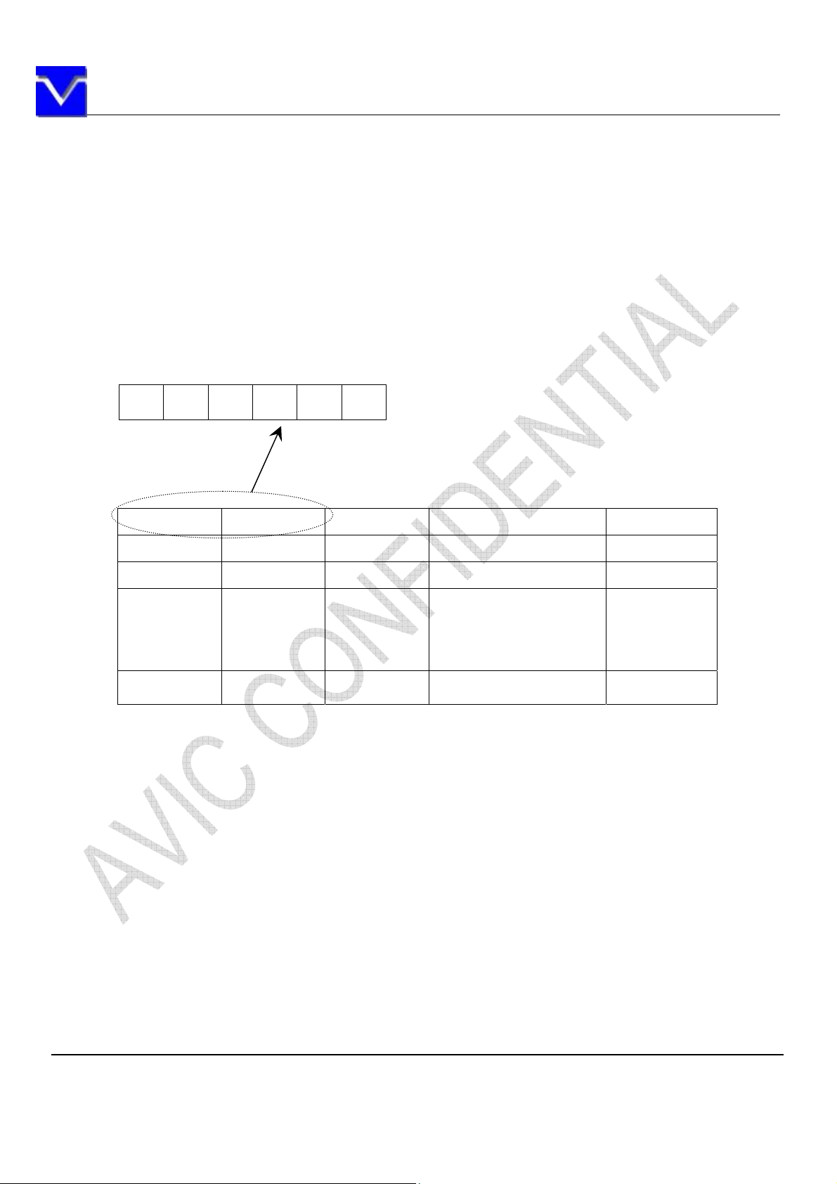
9.3 PIXEL DATA ALIGNMENT OF DISPLAY IMAGE
The following chart is the coordinates of per pixel
D(1,1) D(2,1)
RA GA BA RB GB BB
Odd Pixel: RA= R DATA Even Pixel : RB=R DATA
GA= G DATA GB=G DATA
BA= B DATA BB=B DATA
D(1,1) D(2,1) D(3,1) ••• D(800,1)
D(1,2) D(2,2) D(3,2) ••• D(800,2)
D(1,3) D(2,3) D(3,3) ••• D(800,3)
•
•
•
D(1,600) D(2,600) D(2,600) ••• D(800,600)
•
•
•
•
•
•
•••
•••
•••
•
•
•
The information contained herein is the exclusive property of SHANGHAI AVIC OPTOELECTRONICS
Corporation, and shall not be distributed, reproduced, or disclosed in whole or in part without prior written
permission of SHANGHAI AVIC OPTOELECTRONICS Corporation.
Page 17 of 32
Page 18
SHANGHAI AVIC OPTOELECTRONICS Q/S1021-2011
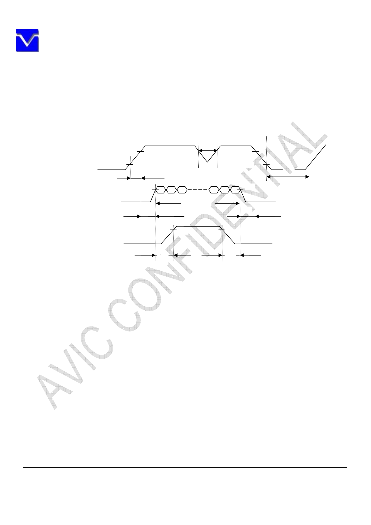
9.4. POWER SUPPLY VOLTAGE SEQUENCE
9.4.1 The sequence of backlight and power
t<10ms *1
4.5V
4.0V
VDD
0V
ON
90%
10%
t1
Display Signals*2
0V
Backlight signal
t5 t6
Timing Specifications:
t1 :0.47ms<t1 <10ms;
t2 :0.5 ms<t2 <50ms;
t3 :0ms<t3 <50ms;
t4 :t4 >1000ms;
t5 :t5 >200ms;
t6 :t6 >200ms;
*1. When VDD is on, but the value is lower than 4.5V, a protection circuit may work, then the module may
not display.
*2 The signal line is not connected with the module, at the end of cable the terminal resistor of 100
should be added.
Note1: Display signals (D0+/-, D1+/-, D2+/-, D3+/- and CK+/-) must be “0” voltage, exclude the VALID
period (See above sequence diagram). If these signals are higher than 0.3 V, the internal circuit is damaged.
If some of display signals of this product are cut while this product is working, even if the signal
input to it once again, it might not work normally. If customer stops the display signals, they
should cut VDD.
Note2: When VDD is on, it should be set above 4.0V.
The information contained herein is the exclusive property of SHANGHAI AVIC OPTOELECTRONICS
Corporation, and shall not be distributed, reproduced, or disclosed in whole or in part without prior written
permission of SHANGHAI AVIC OPTOELECTRONICS Corporation.
Page 18 of 32
Page 19
SHANGHAI AVIC OPTOELECTRONICS Q/S1021-2011
Note3: The backlight power supply voltage should be inputted within the valid period of display and
function signals, in order to avoid unstable data display.
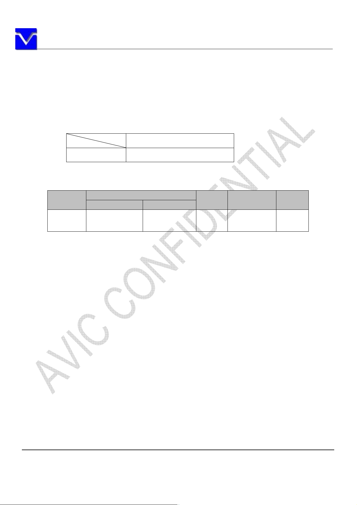
9.4.2 Power supply voltage ripple
When the power supply is designed, the next form can give the reference. If the voltage ripple is
over the value in next form, the noise should be seen in display area.
Ripple (Measured at input terminal of power supply)
Ripple voltage
VDD (3.3V to drive the panel)
200mVP-P(Including spike noise)
9.4.3 Fuse
Parameter
Type Supplier
VDD FCC16152ABTP KAMAYA
Note1: There are different power supply systems from the power input terminal. The power supply
capacity should be less than the fusing current. If the power supply capacity is above the fusing current, the
fuse may blow in a short time, and then nasty smell, smoking and so on may occur.
Fuse
Rating Fusing current Remarks
1.5A
32V
-
The information contained herein is the exclusive property of SHANGHAI AVIC OPTOELECTRONICS
Corporation, and shall not be distributed, reproduced, or disclosed in whole or in part without prior written
permission of SHANGHAI AVIC OPTOELECTRONICS Corporation.
Page 19 of 32
Page 20
SHANGHAI AVIC OPTOELECTRONICS Q/S1021-2011
10. OPTICS
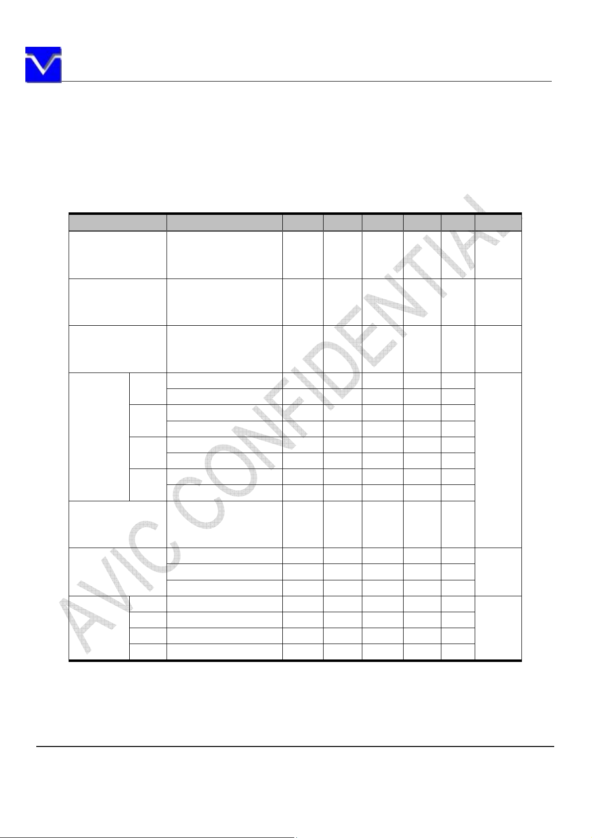
10.1 Optical characteristics
Note1 ,Note2
Parameter Note1 Condition Symbol min. typ. max. Unit Remarks
White at center
Luminance
Contrast ratio
Luminance uniformity
White
Red
Chromaticity
Green
Blue
Color gamut
Response time
Right U=0°, D=0°, CR10 R - 80 -
Viewing
angle
Left U=0°, D=0°, CR10 L - 80 -
Up R=0°, L=0°, CR10 U - 65 -
Down R=0°, L=0°, CR10 D - 75 -
R=0°, L=0°
U=0
°, D=0°
White/Black at center
R=0°, L=0°
U=0
°, D=0°
White
R=0°, L=0°
U=0
°, D=0
X coordinate Wx 0.313 -
Y coordinate Wy 0.329 -
X coordinate Rx - TBD - -
Y coordinate Ry - TBD - -
X coordinate Gx - TBD - -
Y coordinate Gy - TBD - -
X coordinate Bx - TBD - -
Y coordinate By - TBD - -
°, L=0°,
R=0
U=0
°, D=0
At center,against NTSC
White to black Ton - 10 (20) ms
Black to white Toff - 25 (30) ms
Ton+ Toff - - 35 (50) ms
L - 450 - cd/m
CR - 700 - - Note3
LU - 1.25 (1.33) - Note4
C - 55 - %
2
-
Note5
Note6
Note7
。
。
。
。
Note8
The information contained herein is the exclusive property of SHANGHAI AVIC OPTOELECTRONICS
Corporation, and shall not be distributed, reproduced, or disclosed in whole or in part without prior written
permission of SHANGHAI AVIC OPTOELECTRONICS Corporation.
Page 20 of 32
Page 21
SHANGHAI AVIC OPTOELECTRONICS Q/S1021-2011
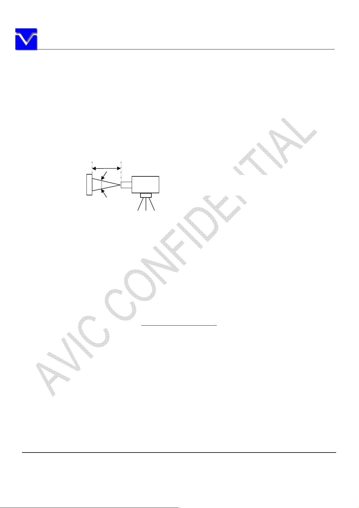
50cm
(Product)
S
pectroradiometer
(TOPCON S
Note1: The values in upper table are only initial
Note2: Measurement conditions are as follows.
Ta= 25
Horizontal cycle=55.56KHz, Vertical cycle=60.0Hz
Optical characteristics are measured at luminance saturation after 30minutes from
working the product in the dark room. Also measurement method for luminance is as
follows.
LCD module
Note 3: See“10.2 Definition of contrast ratio”.
Note 4: See“10.3 Definition of luminance uniformity”.
Note 5: CIE 1931 Chromaticity Diagram Standard.
Note 6: Product surface temperature: TopF = 33.0 °C
Note 7: See “10.4 Definition of response time”.
Note 8: See “10.5 Definition of viewing angle”.
°C, VDD= 3.3V, IBL= 80mArms/led, Display mode: VGA,
1º
characteristics.
Luminance Meter (TOPCON BM-5A)
R-3)
10.2 Definition of contrast ratio
The contrast ratio is calculated by using the following formula.
Contrast ratio(CR)= Luminance of white screen
Luminance of black screen
The information contained herein is the exclusive property of SHANGHAI AVIC OPTOELECTRONICS
Corporation, and shall not be distributed, reproduced, or disclosed in whole or in part without prior written
permission of SHANGHAI AVIC OPTOELECTRONICS Corporation.
Page 21 of 32
Page 22
SHANGHAI AVIC OPTOELECTRONICS Q/S1021-2011
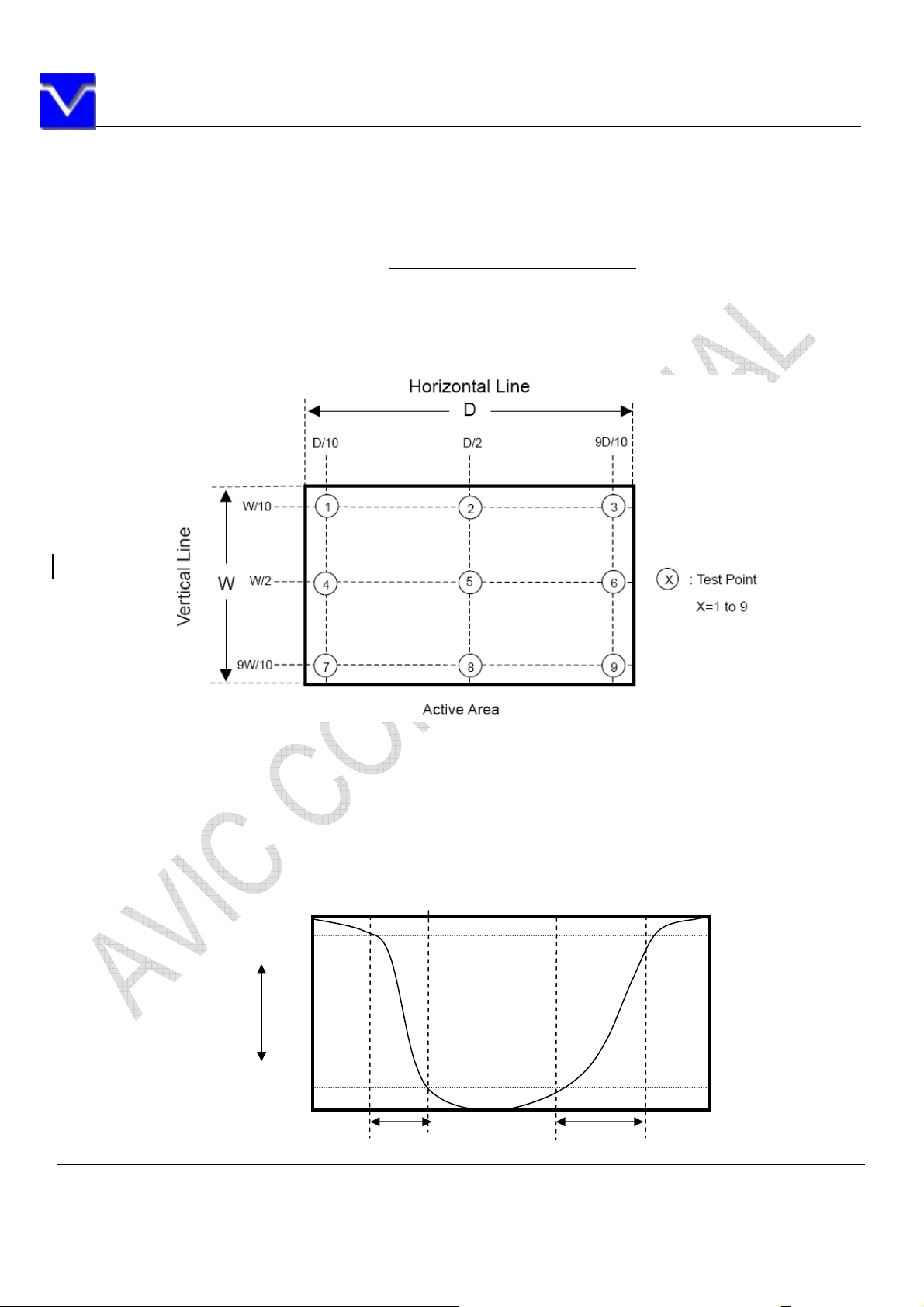
10.3 Definition of luminance uniformity
The luminance uniformity is calculated by using the following formula.
Luminance uniformity(LU)=Maximum luminance from ① to ⑨
Minimum luminance from ① to ⑨
The luminance is measured at near the 9 points shown below.
171 512 853
128
384
①
②
③
640
④
⑤
10.4 Definition of response times
Response time is measured, the luminance changes from “white” to “black”, or “black” to
“white” on the same screen point, by photo-detector. Ton is the time it takes the luminance
change from 90% down to 10%. Also Toff is the time it takes the luminance change from 10% up
to 90%. (See the following diagram.)
100%
90%
White
Luminance
Black
10%
0%
Ton Toff
Normal axis (Perpendicular)
The information contained herein is the exclusive property of SHANGHAI AVIC OPTOELECTRONICS
Corporation, and shall not be distributed, reproduced, or disclosed in whole or in part without prior written
permission of SHANGHAI AVIC OPTOELECTRONICS Corporation.
Page 22 of 32
Page 23
SHANGHAI AVIC OPTOELECTRONICS Q/S1021-2011
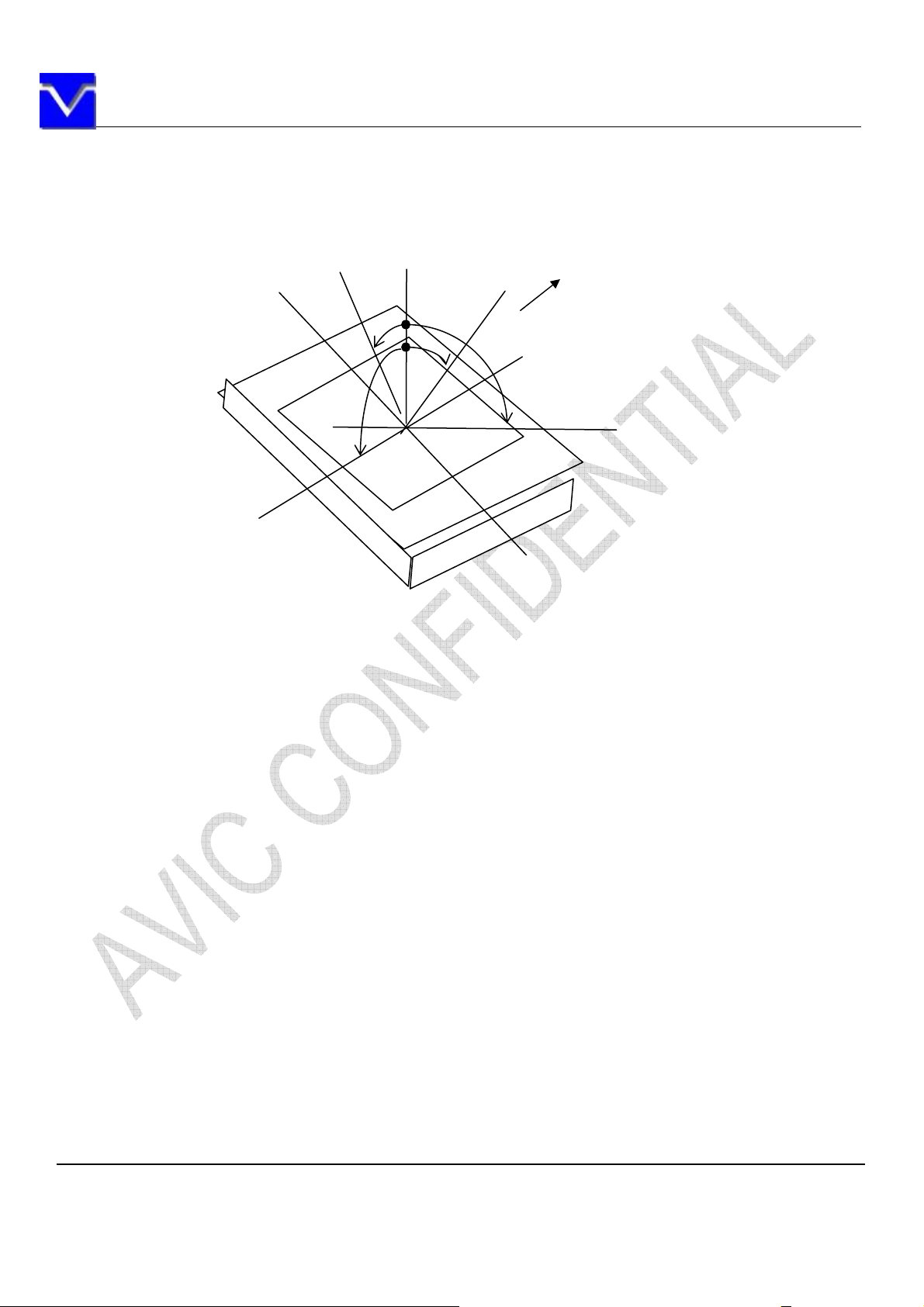
10.5 Definition of viewing angles
Left
Lower
D
12 o’clock
L
Upper
U
R
Right
The information contained herein is the exclusive property of SHANGHAI AVIC OPTOELECTRONICS
Corporation, and shall not be distributed, reproduced, or disclosed in whole or in part without prior written
permission of SHANGHAI AVIC OPTOELECTRONICS Corporation.
Page 23 of 32
Page 24
SHANGHAI AVIC OPTOELECTRONICS Q/S1021-2011
11. MARKINGS
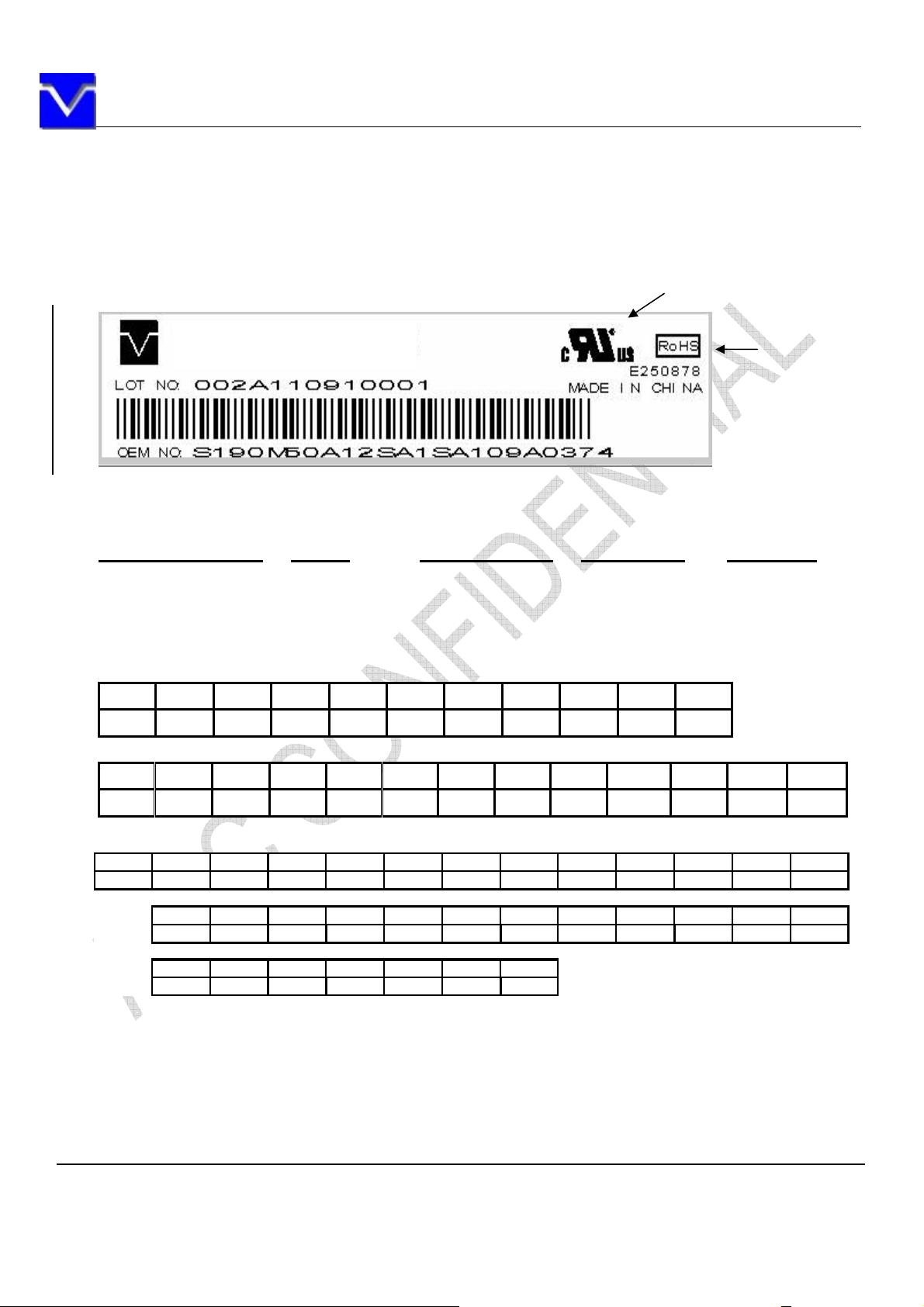
The various markings are attached to this product. See “11.2 INDECATION LOCATIONS” for attachment
positions.
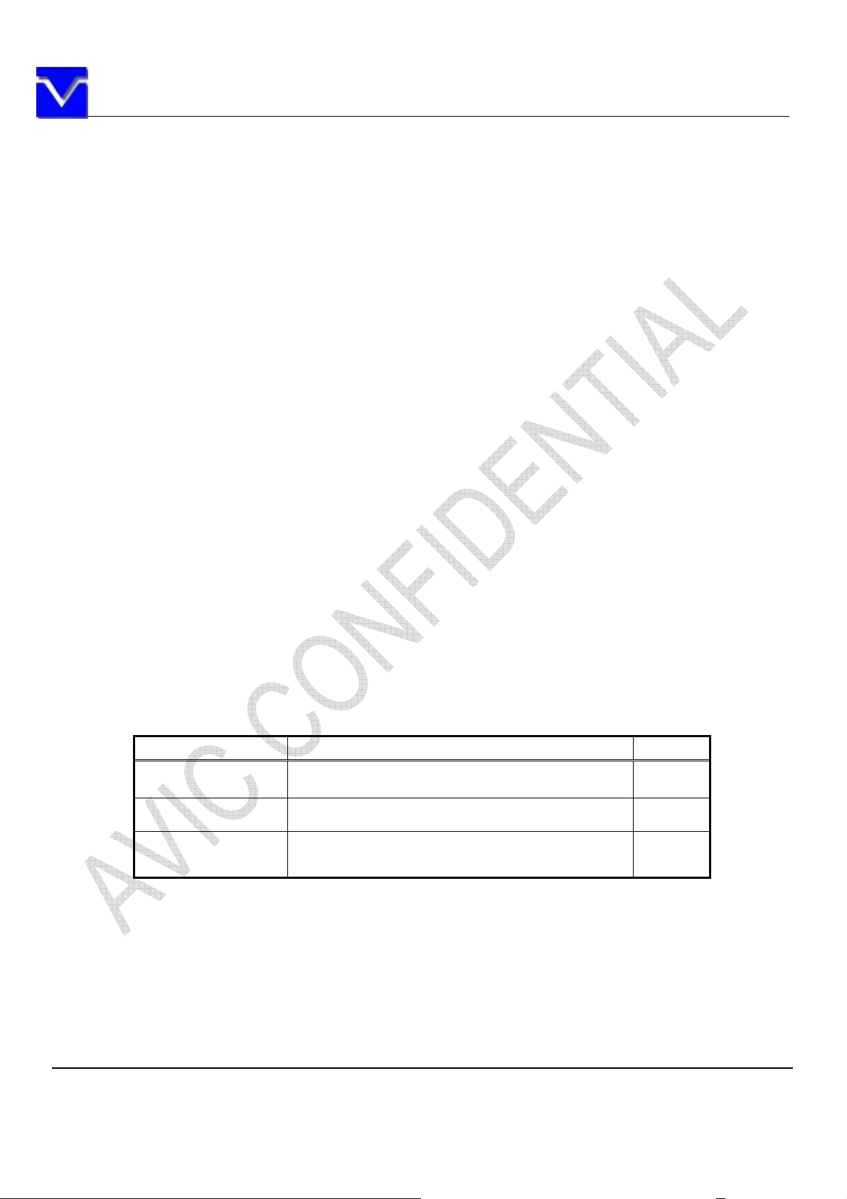
11.1 PRODUCT LABEL
UL MARK
TM121SDS01
Note1: The meaning of OEM number, Example: S190M50A12SA1SA109A0001
S190M50A 12 SA1SA1 09A 0001
Module Number Source & Gate
Driver IC Code
Date code:
1st Character Year Codes
Month
Code
2010 2011 2012 2013 2014 2015 2016 2017 2018 So on
0 1 2 3 4 5 6 7 8
2nd Character Month Codes
Month January February March April May June July August SeptemberOctober NovemberDecember
Location Line# Date code Serial Number
ROHS Mark
Code 1 2 3 4 5 6 7 8 9 A B C
3rd Character Day Codes
Day 1st 2nd 3rd 4th 5th 6th 7th 8th 9th 10th 11st 12nd
Code123456789ABC
13rd 14th 15th 16th 17th 18th 19th 20th 21st 22nd 23rd 24th
DEFGHJKLMNPQ
25th 26th 27th 28th 29th 30th 31st
RSTUVWX
Note2: Do not attach anything such as label and so on, on the product label! In case repair the product,
AVIC needs the contents of product label such as the lot number, inspection date and so on, to identify the
warranty period with individual product. If AVIC cannot decipher the contents of product label, such repair shall
be entitled to charge. Also AVIC may give a new lot number to reconditioned products.
The information contained herein is the exclusive property of SHANGHAI AVIC OPTOELECTRONICS
Corporation, and shall not be distributed, reproduced, or disclosed in whole or in part without prior written
permission of SHANGHAI AVIC OPTOELECTRONICS Corporation.
Page 24 of 32
Page 25
SHANGHAI AVIC OPTOELECTRONICS Q/S1021-2011
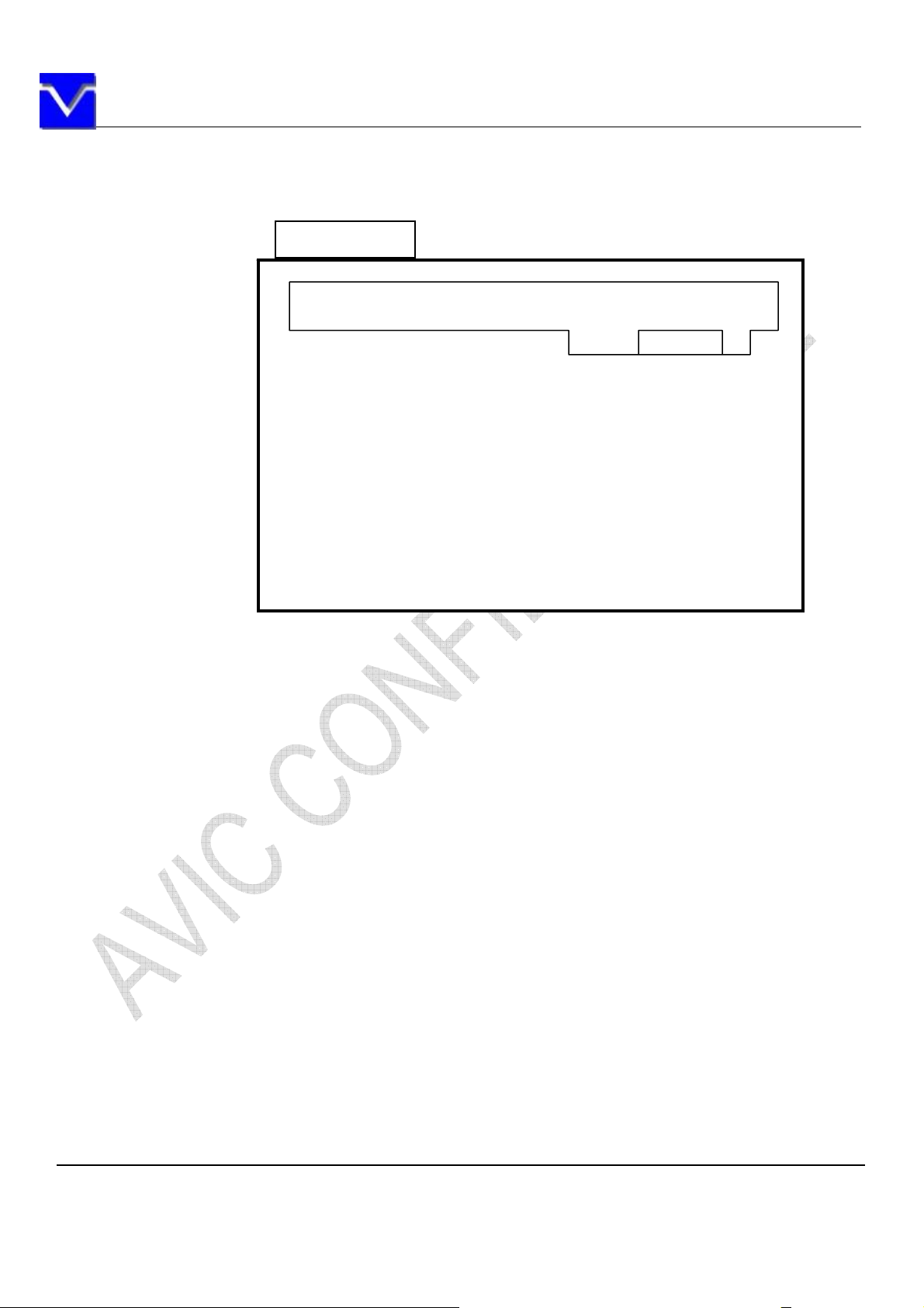
11.2 INDICATION LOCATIONS
Product rear side
Disposal method marking Barcode label Product label
The information contained herein is the exclusive property of SHANGHAI AVIC OPTOELECTRONICS
Corporation, and shall not be distributed, reproduced, or disclosed in whole or in part without prior written
permission of SHANGHAI AVIC OPTOELECTRONICS Corporation.
Page 25 of 32
Page 26
SHANGHAI AVIC OPTOELECTRONICS Q/S1021-2011
12. PACKING, TRANSPORTATION AND DELIVERY
AVIC will pack products to deliver to customer in accordance with AVIC packing specifications, and will
deliver products to customer in such a state that products will not suffer from a damage during
transportation .The delivery conditions are as follows.
12.1 PACKING
(1) Packing box
8 products are packed up with the maximum in a packing box(See “12.5 OUTLINE FIGURE FOR
PACKING “).
Products are put into a plastic bag for prevention of moisture with cushion, and then the bag is sealed up
with heat sealing.
The type name and quality are shown on outside of the packing box, either labeling or printing.
(2) Pallet Packing (See”12.5 OUTLINE FIGURE FOR PACKING “)
Packing boxes are tired on a cardboard pallet.(8 boxes×4 tiers maximum)①
Cardboard sleeve and top cap are att② ached to the packing boxes, then they are fixed by a band.
12.2 INSPECTION RECORD SHEET
Inspection record sheets are included in the packing box with delivery products to customer. It is
summarized to a number of products for pass/fail assessment.
12.3 TRANSPORTATION
The product is transported by vehicle, aircraft or shipment in the state of pallet packing.
12.4 SIZE AND WEIGHT FOR PACKING BOX
Parameter Packing box Unit
Size TBD mm
Weight TBD kg
Total weight TBD kg
The information contained herein is the exclusive property of SHANGHAI AVIC OPTOELECTRONICS
Corporation, and shall not be distributed, reproduced, or disclosed in whole or in part without prior written
permission of SHANGHAI AVIC OPTOELECTRONICS Corporation.
Page 26 of 32
Page 27

SHANGHAI AVIC OPTOELECTRONICS Q/S1021-2011
12.5 OUTLINE FIGURE FOR PACKING
TBD
The information contained herein is the exclusive property of SHANGHAI AVIC OPTOELECTRONICS
Corporation, and shall not be distributed, reproduced, or disclosed in whole or in part without prior written
permission of SHANGHAI AVIC OPTOELECTRONICS Corporation.
Page 27 of 32
Page 28
SHANGHAI AVIC OPTOELECTRONICS Q/S1021-2011
13. PRECAUTIONS
13.1 MEANING OF CUTION SIGNS
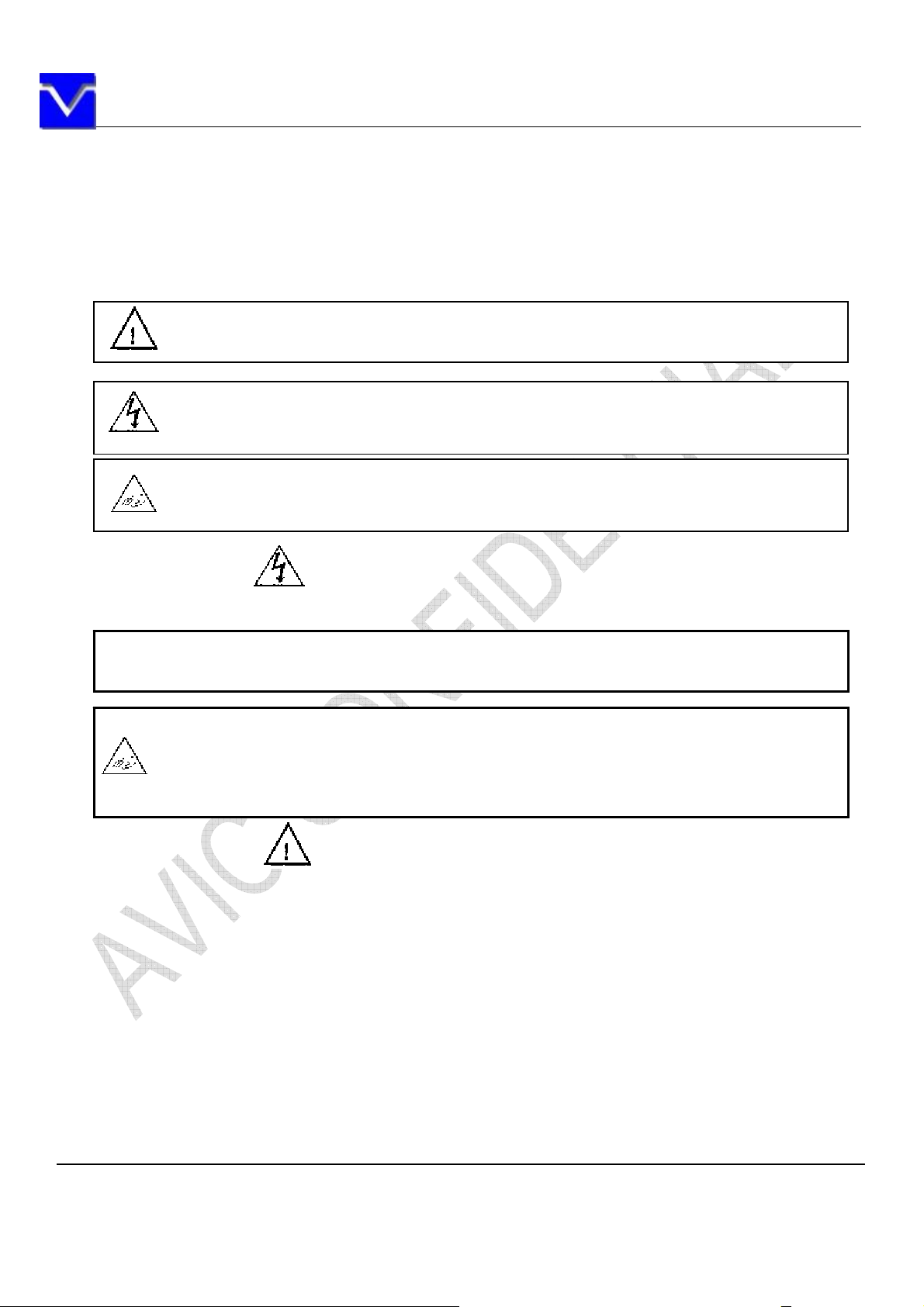
The following caution signs have very important meaning .Be sure to read “13.2 CAUTIONS” and “13.3
ATTENTIONS”, after understanding these contents!
This sign have the meaning that customer will be injured by himself or the product will
sustain a damage, if customer has wrong operations.
This sign has the meaning that customer will get an electrical shock, if customer has
wrong operations.
This sign has the meaning that customer will be injured by himself, if customer has
wrong operations.
13.2 CAUTIONS
*
Do not touch lamp cables while turn on .Customers will be in danger of an electric shoc
k
* Do not touch the working backlight and IC. Customers will be in danger of burn injury.
* Do not shock and press the LCD panel and the backlight! There is a danger of breaking,
because they are made of glass.(shock :To be not greater 294m/s
11ms, Pressure: To be not greater 19.6N)
2
and to be not greater
13.3 ATTENTIONS
13.3.1 Handling of the product
① Take hold of both ends without touch the circuit board when customer pulls out products (LCD
modules) from inner packing box. If customer touches it, products may be broken down or out of
adjustment, because of stress to mounting parts.
② Do not hook cables nor pull connection cables such as flexible cable and so on , for fear of
damage.
③ If customer puts down the product temporarily, the product puts on flat subsoil as a display side
turns down.
④ Take the measures of electrostatic discharge such as earth band, ionic shower and so on, when
customer deal with the product, because products may be damaged by electrostatic.
The information contained herein is the exclusive property of SHANGHAI AVIC OPTOELECTRONICS
Corporation, and shall not be distributed, reproduced, or disclosed in whole or in part without prior written
permission of SHANGHAI AVIC OPTOELECTRONICS Corporation.
Page 28 of 32
Page 29

SHANGHAI AVIC OPTOELECTRONICS Q/S1021-2011
⑤ The torque for mounting screws must never exceed 0.34N-m. Higher torque values might result
in distortion of the bezel.
⑥ The product must be installed using mounting holes without undue stress such as bends or twist
(See outline drawings).And do not add undue stress to any portion (such as bezel flat area)
except mounting hole portion.
⑦ Bends or twist described above and undue stress to any portion except mounting hole portion
may cause display un-uniformity.
⑧ Do not press or rub on the sensitive display surface .If customer clean on the panel surface, AVIC
recommends using the cloth with ethanolic liquid such as screen cleaner for LCD.
⑨ Do not push-pull the interface connectors while the product is working, because wrong power
sequence may break down the product.
⑩ Do not bend or unbend the lamp cable at the near part of the lamp holding rubber, to avoid the
damage for high voltage side of the lamp. This damage may cause a lamp breaking and
abnormal operation of high voltage circuit.
13.3.2 Environment
① Do not operate or store in high temperature, high humidity, dewdrop atmosphere or corrosive
gases. Keep the product in antistatic pouch in room temperature, because of avoidance for dusts
and sunlight, if customer stores the product.
② In order to prevent dew condensation occurring by temperature difference, the product packing
box must be opened after leave under the environment of an unpacking room temperature
enough. Because a situation of dew condensation occurring is changed by the environment
temperature and humidity, evaluate the leaving time sufficiently. (Recommendation leaving time:
6 hour or more with packing state)
③ Do not operate in a high magnetic field .Circuit boards may be broken down by it.
④ This product is not designed as radiation hardened.
⑤ Use an original protection sheet on the product surface (polarizer). Adhesive type protection
sheet should be avoided, because it may change color or properties of the polarizer.
The following items are neither defects nor failures.
13.3.3 Characteristics
① ambient temperature.
② The LCD may be seemed luminance non-uniformity, flicker, vertical seam or small spot by display
patterns.
③ Optical characteristics (e.g. luminance, display uniformity, etc.) gradually is going to change
depending on operating time ,and especially low temperature, because the LCD has cold
cathode fluorescent lamps.
④ Do not display the fixed pattern for a long time because it may cause image sticking .Use a
screen saver, if the fixed pattern is displayed on the screen.
⑤ The display color may be changed by viewing angle because of the use of condenser sheet in the
backlight.
⑥ Optical characteristics may be changed by input signal timings.
The information contained herein is the exclusive property of SHANGHAI AVIC OPTOELECTRONICS
Corporation, and shall not be distributed, reproduced, or disclosed in whole or in part without prior written
permission of SHANGHAI AVIC OPTOELECTRONICS Corporation.
Page 29 of 32
Page 30

SHANGHAI AVIC OPTOELECTRONICS Q/S1021-2011
⑦ The interference noise of input signal frequency for this product and luminance control frequency
of customer’s backlight inverter may appear on a display. Set up luminance control frequency of
backlight inverter so that the interference noise doses not appear.
13.4 Other
① All GND and VCC terminals should be used without a non-connected line.
② Do not disassemble a product or adjust volume without permission of AVIC.
③ Pay attention not to insert waste materials inside of products, if customer uses screw nails.
④ Pack the product with original shipping package, because of avoidance of some damages during
transportation, when customer returns it to AVIC for repair and so on .
⑤ Not only the module but also the equipment should be packed and transported as the module.
becomes vertical .Otherwise, there is the fear that a display dignity decreases by an impact or
vibrations.
The information contained herein is the exclusive property of SHANGHAI AVIC OPTOELECTRONICS
Corporation, and shall not be distributed, reproduced, or disclosed in whole or in part without prior written
permission of SHANGHAI AVIC OPTOELECTRONICS Corporation.
Page 30 of 32
Page 31
SHANGHAI AVIC OPTOELECTRONICS Q/S1021-2011
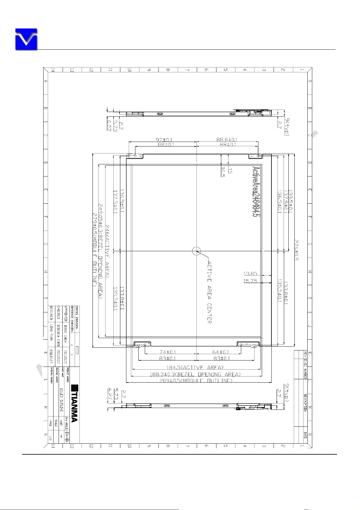
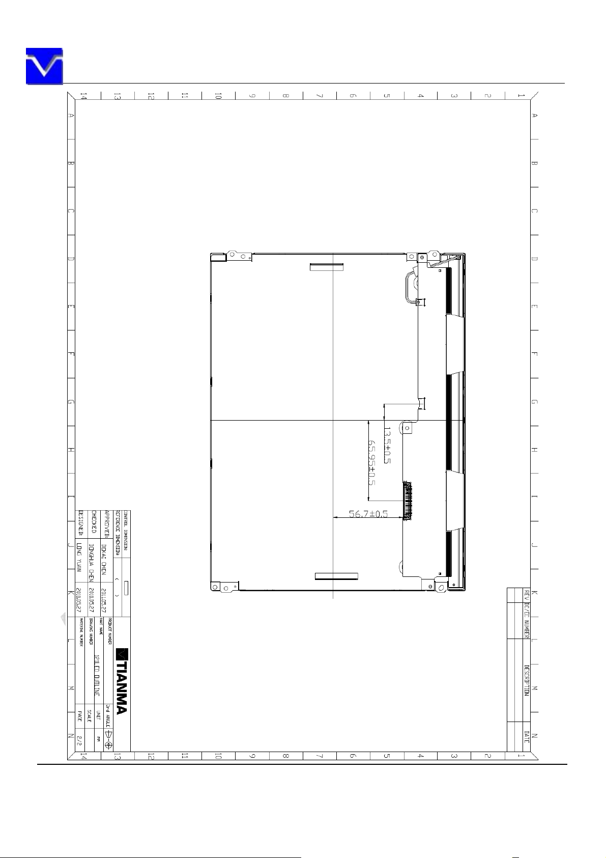
14.OUTDRAWING
The information contained herein is the exclusive property of SHANGHAI AVIC OPTOELECTRONICS
Corporation, and shall not be distributed, reproduced, or disclosed in whole or in part without prior written
permission of SHANGHAI AVIC OPTOELECTRONICS Corporation.
Page 31 of 32
Page 32
SHANGHAI AVIC OPTOELECTRONICS Q/S1021-2011
The information contained herein is the exclusive property of SHANGHAI AVIC OPTOELECTRONICS
Corporation, and shall not be distributed, reproduced, or disclosed in whole or in part without prior written
permission of SHANGHAI AVIC OPTOELECTRONICS Corporation.
Page 32 of 32
 Loading...