

Page 1

1
High Definition Intelligent IR
IP Auto-tracking Speed Dome Camera
User’s Manual
Page 2

2
CONTENT
Chapter 1 Precautions ..................................................................................................................... 3
Chapter 2 Structure ......................................................................................................................... 5
Chapter 3 Functions Description .................................................................................................... 6
3.1 Features.............................................................................................................................. 6
3.2 Function Instruction.......................................................................................................... 8
3.3 Specification ....................................................................................................................... 8
Chapter 4 Installation Guide ......................................................................................................... 11
4.1 Preparation ...................................................................................................................... 11
4.2 Installation ....................................................................................................................... 11
4.3 Interface Instruction ....................................................................................................... 14
4.4 Installation Procedures (Take Wall Mount as Example) .............................................. 15
4.5 External Cable Connection Instruction .......................................................................... 17
Chapter 5 WEB Instruction ........................................................................................................... 18
5.1 System Requirement ....................................................................................................... 18
5.2 Built-in Web Instruction ................................................................................................. 18
5.3 Log in ................................................................................................................................ 18
5.4 Preview............................................................................................................................. 19
5.5 Playback ........................................................................................................................... 21
Chapter 6 Configuration ................................................................................................................ 23
6.1 Audio Video Set ................................................................................................................ 23
6.2 Dome Set .......................................................................................................................... 25
6.3 VCA ................................................................................................................................... 31
6.4 OSD ................................................................................................................................... 38
6.5 Storage Management ....................................................................................................... 39
6.6 Network Management ..................................................................................................... 40
6.7 User management ........................................................................................................... 43
6.8 Alarm Management ......................................................................................................... 43
6.9 PTZ Management and Control ........................................................................................ 46
6.10 Advance .......................................................................................................................... 46
Chapter 7 Simple Problem-solving Methods ............................................................................... 48
Chapter 8 After-sales Service ....................................................................................................... 50
Appendix I Lightning and Surge ........................................................................................... 50
Appendix II::Hoisting construction Guide ........................................................................... 53
Page 3
3
Chapter 1 Precautions
In order to avoid danger and operate the products correctly, please read this manual carefully
before installation.
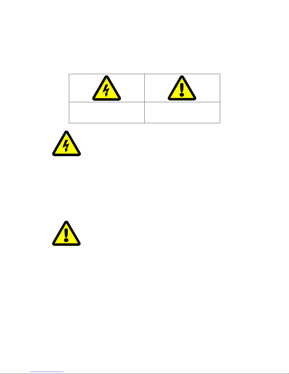
The precaution contains two parts “Warning” and “Note” as following:
Warnings alert the user to avoid
the potential risk of death or serious
injury
Cautions alert the user to avoid the
potential risk of injury or property
damage
Warning:
● Please use AC 24V power supply meeting SELV(Safety Extra Low Voltage) and in accordance with
IEC60950-1 compliance with Limited Power Source
● Please contact nearest distributor or service center if the products don’t work properly, do not
remove or modify the device in any way (unauthorized modification or repair problems caused by
your own risk).
● Please don’t expose the indoor product to rain or moisture.
● The installation should be performed by professional staff, and comply with local regulations.
● Please mount easily using power protection device in the wire installation.
● Please make sure the connection can withstand at least 50 Newtons vertically downward pull.
Note:
● Please check if the power supply is correct.
● In transportation and storage process, please prevent stress, severe vibration and immersion to
avoid any damage
● Please don’t touch the image sensor and housing directly, if necessary, please gently clean with
alcohol dampened.
● Please don’t touch the cooling components directly, in order to avoid burns.
● Please don’t focus aligned glare (such as lighting, sunlight, etc.), otherwise it will easily lead to
too bright or pull light phenomena, also affect the image sensor life.
● The laser beam may burn the image sensor, so when it is used, please don’t expose the image
sensor in laser beam.
● Please don’t put it in the damp, dusty, extreme heat, extreme cold, strong electromagnetic
radiation places.
● Please make sure the installation location keep enough distance from the electromagnetic
Page 4

4
sensitive devices surrounding to avoid electromagnetic interference.
● Please prevent heat buildup and keeping the surrounding ventilation.
● Please prevent the speed dome from water or any liquid.
● The product must be carried by original package, either in delivery to users or in return delivery
to the factory for repairing. Otherwise, damage caused in transportation will not be covered by
warranty.
● The battery replaced incorrectly will lead to use of exceptions, and we don’t recommend users to
replace directly; If necessary, please use batteries recommended by the manufacturer (for devices
with battery).
● Please don’t dismantle internal parts, please turn to qualified maintenance professionals to carry
out repairs
● Long-term high speed cruising may cause slip rings broken and belt aging, also affect speed dome
life.
● Working Environment
Speed Dome
Environmental temperature
-40℃~+65℃
Moisture
<95%(Non-condensing)
Atmospheric pressure
86~106KPa
Power
AC24V/2.0A
Note: make sure outdoor installation meets water-proof requirements.
Page 5
5
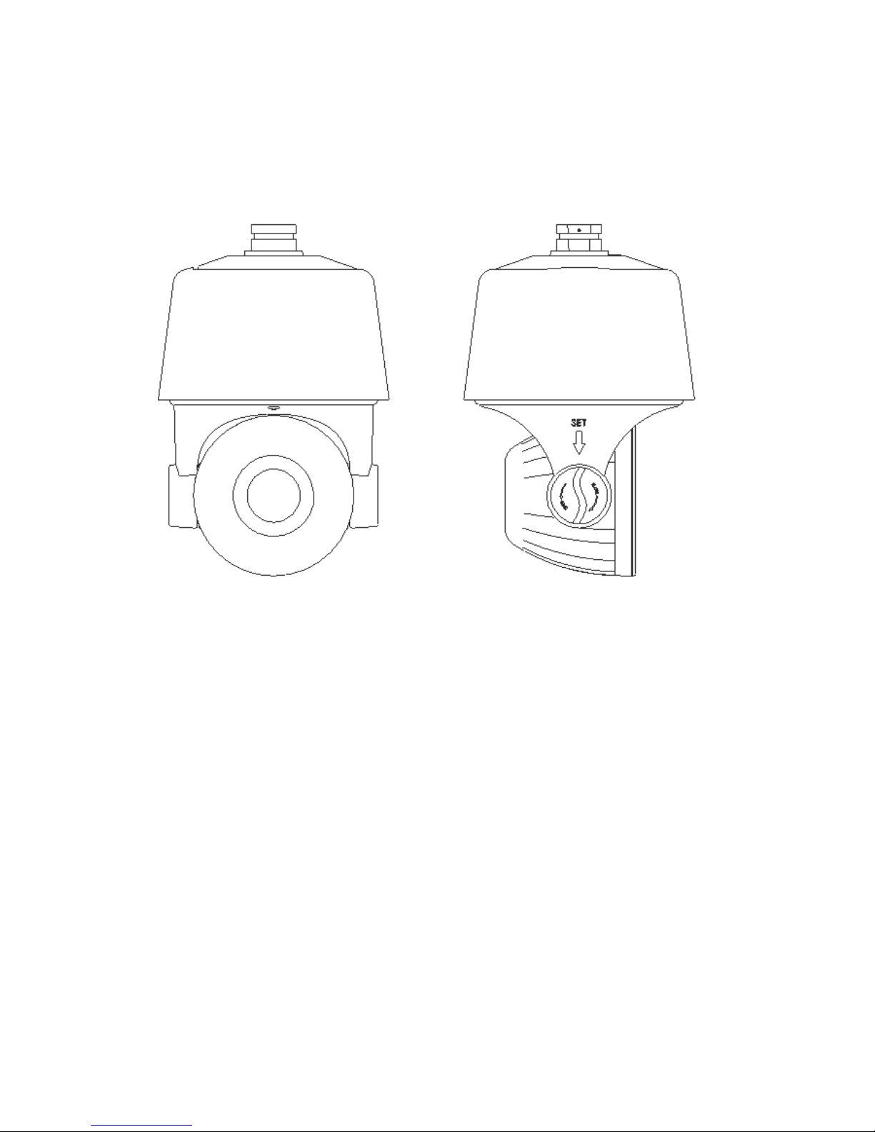
Chapter 2 Structure
Front view Side view
Page 6

6
Chapter 3 Functions Description
3.1 Features
1. Built-in Decoder
● HD IP Speed Dome, support 720P 25/30fps or 1080P 25/30fps output.
● Support English menu
● Support standard Onvif
● Power-off protection, no data loss
● RJ-45 port network port
● Support PELCO_P,PELCO_D protocols.
● Support 3D location
● Support standby function
● 225 programmable presets
● 8 cruising tracks, each cruising track has 32 preset positions
● 8 auto scan tracks, the left and right boundaries and scan speed can be set
● Support OSD, date and time display
● Support 1 channel alarm input and 1 channel alarm output
● Support TF storage and local capture
2. Integrated Universal Speed Change Rotator
● Manual Speed:0.05°~160°/s, Max speed 240°/s
● 360° continuous pan rotation, tilt -11°~90° auto flip
● Stepless speed change, auto zoom/speed matching
● Classic double bearing structure, more stable operation
● Delicate stepping motor, stable, sensitive and accurate
3. All-weather Outdoor Design
● Sensor intelligent control
● Double housing structure
● IP66 water proof
● Support anti- lightning and anti-surge
Page 7

7
4. Camera Module
● Support auto iris, auto focus and auto BLC
● Mini. Illumination 0.5Lux/F1.6(color),0.095Lux/F1.6(B/W)
● Support 3D noise reduction and WDR
5. Network
● Support Ethernet control
● Support remote view and control by browser and client software
● Support Micro SD card
● Support NFS
● Support remote view and control by browser and client software
● Support Micro SD card
● Support for NFS record
● Support four levels user authority
●Support for authorized users and passwords, support HTTPS encryption and IEEE 802.1x
network access control
● Support dual-stream, support H.264/MJPEG, support multi-level video quality configuration,
and support real-time video output resolution 1080p, 960p and 720p
● Support multiple network protocols, IPv4/IPv6, HTTP, HTTPS, 802.1x, Qos, FTP, SMTP, UPnP,
SNMP, DNS, DDNS, NTP, RTSP, RTP,
TCP / IP, DHCP, PPPoE
6. IR Function
● Mini. Illumination 0Lux
● Adopt array IR, low consumption, IR distance 150m
● IR LEDs and zoom auto match
● Support NFS
● Built-in heat treatment and defog systems
● Constant current circuit design, IR LED life >30,000 hours
Page 8

8
3.2 Function Instruction
● Focus/Rotate Auto Match
Speed Dome can auto adjust pan and tilt rotation speed depending on the focus distance.
● Preset Position Setting and Calling
Preset function means the speed dome can memory current pan/tilt angel, focus, zoom, ect. When
need, it can be called upon directly. Our speed dome support up to 255 preset positions.
● Auto Scan
Users can set the left and right boundaries by control keyboard. Then speed dome can scan
between it. It can set up to 8 groups scan path.
● Auto Cruising
Users can program some preset positions into auto cruising sequence, then the speed dome can
track as it. Each cruising tracks has 32 preset positions.
● Pattern Tour
Speed Dome can memory 180s running path. When start pattern tour, speed dome can track as
recording path. It supports 4 groups pattern tour.
● Guard Location
The dome will rotate back to preset position after a period of vacant time.
● Power-off Protection
Speed dome can resume operation status before the power-off, no data loss.
3.3 Specification
Model
Specification
HD IP IR Auto-tracking Speed Dome
Camera
Sensor
1.3M:AR0130-1/3”
CMOS
2M:IMX222-1/2.8” CMOS
Pixel
1.3M
2.1
Image Resolution
Color:0.5 Lux @ (F1.6,50 IRE,ICR close)
B/W:0.095 Lux @ (F1.6,50 IRE,ICR open)
Page 9

9
Resolution
≥720TVL
≥1000TVL
White Balance
Auto / Manual/ATW
GC
Auto /Manual
S/N
>50dB
Noise Reduction
3D&2D
WDR
Support
Electronic Shutter
1/25 ---1/10000s
Day/Night
Auto ICR
Focus
Auto / Manual
Lens
Focal Length
14.7~84.6mm,20X
4.7~94mm,20X
Zoom
3S
Horizontal Angle
54.8°-3.4°
55.5°-3.0°
Near Distance
20~1000mm
Iris
F1.6 ~F2.7
F1.6 ~F3.0
PTZ
Horizontal Rotation
Range
360°continuous rotation
Horizontal Speed
0.05°~160°/s(stepless speed)
Vertical Rotation
Range
11°~90°auto flip
Vertical Speed
0.05°-120°/s
Preset
255
Auto Cruise
8 group, each group can set 32 preset
Auto Scan
Support track, horizontal, vertical, frame, whole view and
random scan
Guard Location
Link preset/scan/cruise/pattern
Power off Memory
Support
Position
Information Display
On/Off
Page 10

10
IR
IR Distance
150m
IR Angle
Zoom matching, far/middle/near
Network
Image resolution
1280×960
1920×1080
Frame rate
50Hz: 25 fps
(1280×960)
25 fps (1280×720)
60Hz: 30 fps
(1280×960)
30 fps (1280×720)
50Hz:25fps(1920×1080)
25fps(1280×960)
25fps(1280×720)
60Hz:30fps(1920×1080)
30fps(1280×960)
30fps(1280×720)
Video Compression
H.264/MJPEG
Audio Compression
G711A/G711U/G726/ADPCM/AAC
Network Protocol
IPv4,HTTP,HTTPS,802.1x, FTP,SMTP,UPnP,SNMP
DNS,DDNS,NTP,RTSP,RTP,TCP/IP,DHCP,PPPoE
Preview Channel
Max 6ch
Stream
Triple
Authority
32 users, 4 level: administrator, browse, browse+control,
browse+control+setup
Safe Mode
Authorized user name and password, HTTPS encryption;
IEEE 802.1x network access control, IP address filtering
Interface
Audio Input
Support
Audio Output
Support
Network
10M/100M
TF Card
Support
Program
Support standard Onvif
Browser
IE8,IE9,IE10,Chrome8+,Firefox3.5+
General
Power
AC24V 40W max
Working
Temperature and
Humidity
-40 ℃-65℃
Humidity<90%
Protection Level
IP66,TVS 4000V lightning protection
Dimensions
Ф230(mm)*350(mm)
Weight
4.8kg
Page 11
11
Chapter 4 Installation Guide
4.1 Preparation
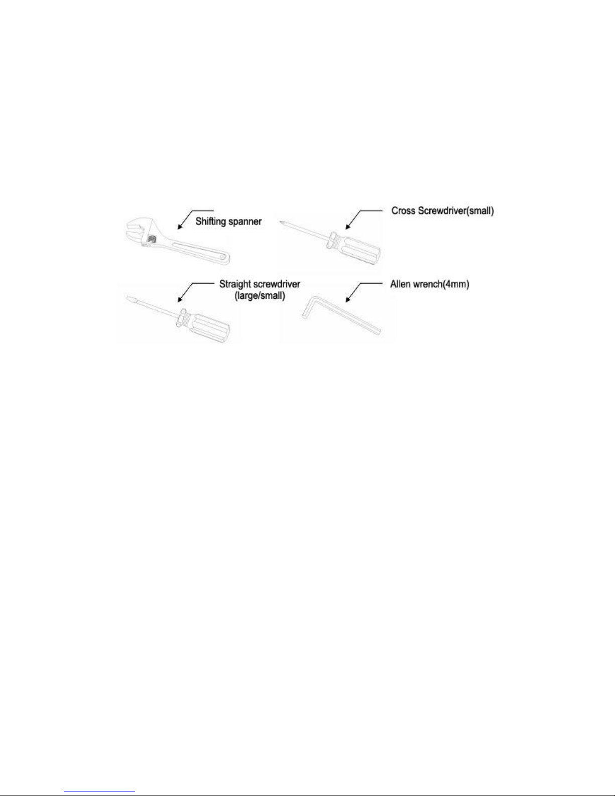
1. Tools:
Please prepare the necessary tools according to specific situations
2. Check installation space and address
Check the space is enough to install the speed dome. The wall must be thick enough to install the
expansion screws and can bear 4 times the weight of the dome camera itself.
3. Please well keep the whole package
After open the package, please well keep them in case need to return to manufacturer if any
problem.
★Note:The non-original package may lead to damage during the transportation.
4.2 Installation
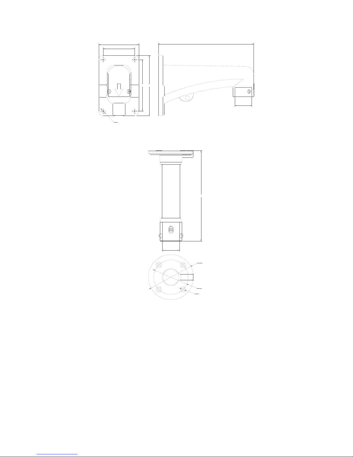
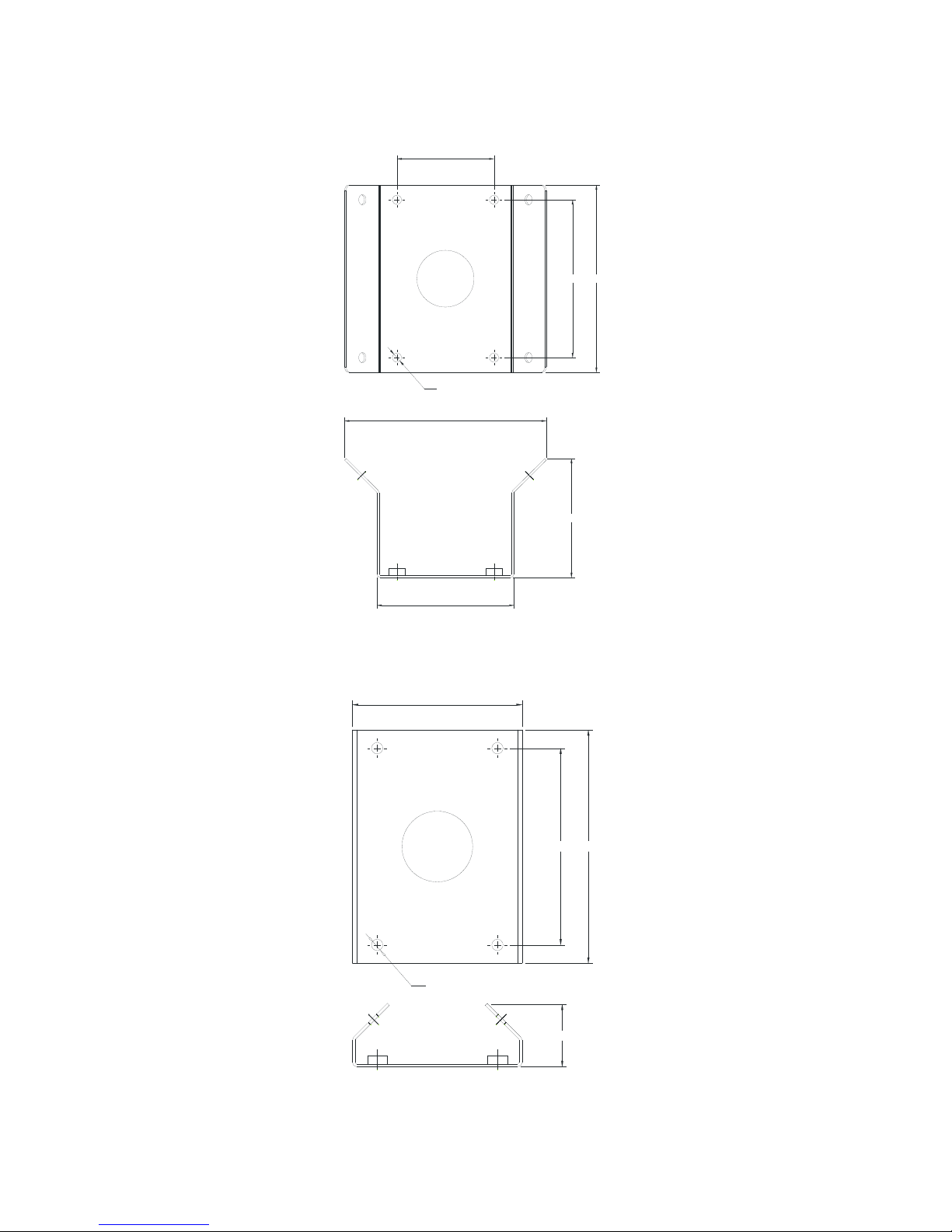
The speed dome supports four types installation as following:
1:Wall mount and dimension:
Page 12
12
Ø45
109
85
139
163
Ø9
258
Wall Mount Bracket Dimension
2:Pedant mount and dimension:
Ø45
Ø118
Ø90
Ø9
236
Pedant Mount Bracket Dimension
Page 13
13
3:External corner and dimension
85
139
164
104
120
M8
176
External Corner Bracket and Dimension
4:Pole mount and dimension:
139
165
120
44
M8
Pole Mount Bracket and Dimension
Page 14
14
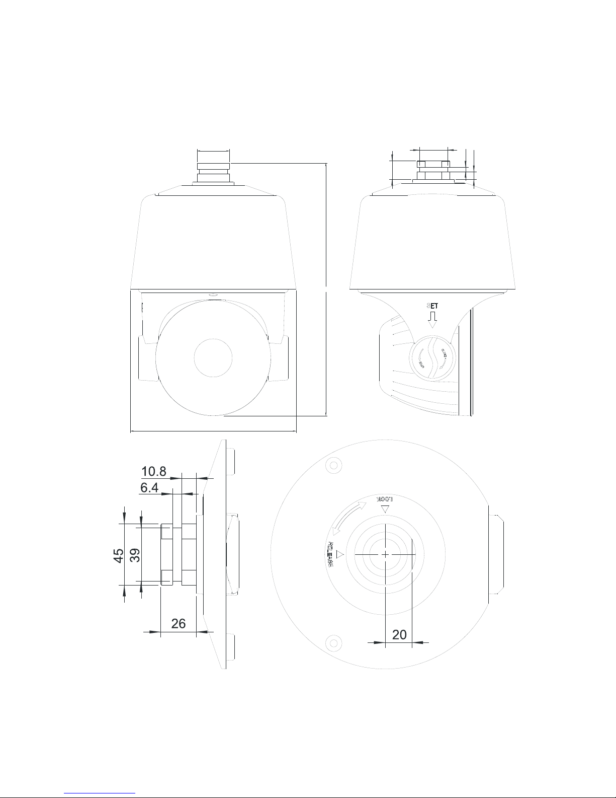
4.3 Interface Instruction
Speed Dome and Bracket Interface Dimension
Ø230
350
Ø45
2
6
6
.
4
1
0
.
8
39
Page 15
15
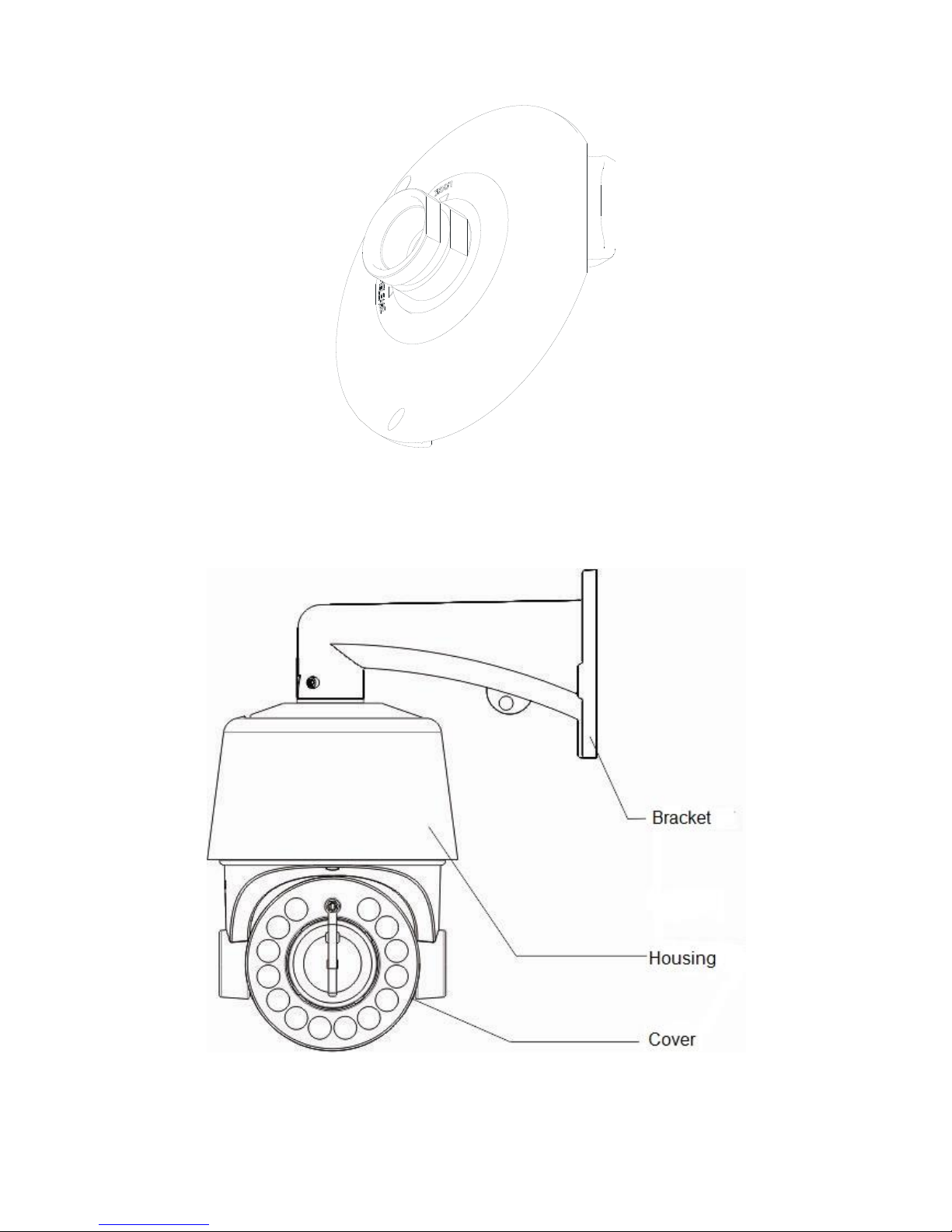
Speed Dome and Bracket Interface Perspective Picture
4.4 Installation Procedures (Take Wall Mount as Example)
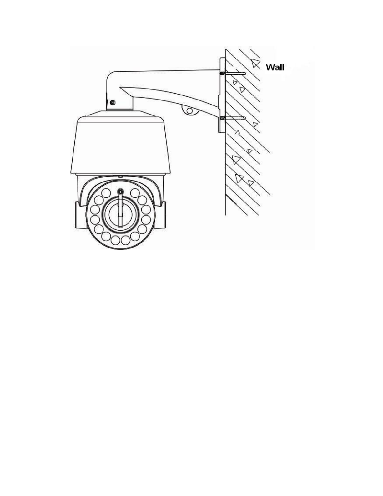
Figure 1
Page 16
16
Figure 2
Steps:
Remove the wall mounting bracket and speed dome, and lead the cable through the bracket and
set aside to the right position. Aligned the screw holes of speed dome to that of bracket, and use
M6 screws to fix. (as Figure 1)
Mark the drill holes position on wall with ink pen for bracket installation, then drill holes and punch
the expansion screws in, then fasten the bracket with M8 screws as Figure 2.
Description:
1) The wall must have sufficient load-bearing capacity.
2) Outdoor installation shall be completely sealed moisture; leads cable should closely along the
bracket wiring as Figure 1.
Page 17
17
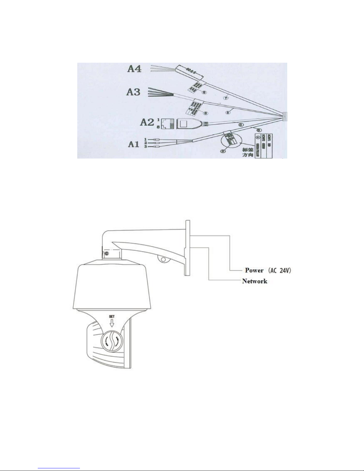
4.5 External Cable Connection Instruction
A1: Power Cable:AC/DC24V;
A2: Network: Connect computer or other devices
A3: Audio Cable: Audio input and output can connect mic and speaker
A4: Alarm Cable:Connect external alarm devices;
Note: Please refer to labels on the cables
Page 18
18
Chapter 5 WEB Instruction
5.1 System Requirement
The IP speed dome web settings support Windows XP, Win7 system, please make sure right
installation and setup of following items:
(1) Display resolution: 1024 * 768 or higher, color: High Color (32-bit).
(2) Please make sure the Windows system install the necessary character style.
5.2 Built-in Web Instruction
When using the network video products for the first time, an ActiveX control is needed. Note: please
use IE browser of windows and make sure the version above 6.0. Do not use any other browser
except Firefox, Google.
(1) Login IP address and enter to ActiveX download interface.
(2)Download ActiveX and click 【Run】to install
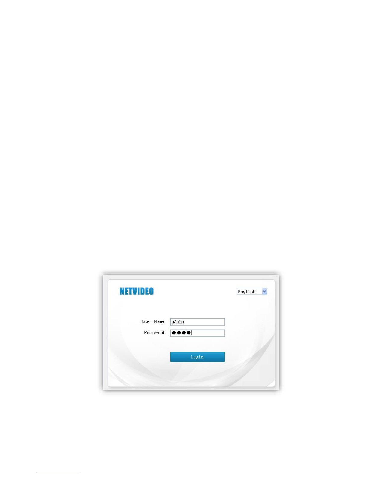
5.3 Log in
Camera default IP address is:192.168.1.2,please make sure computer and IP camera in the
same IP address area.
You need to download Active X plug when first time to use.
Page 19
19
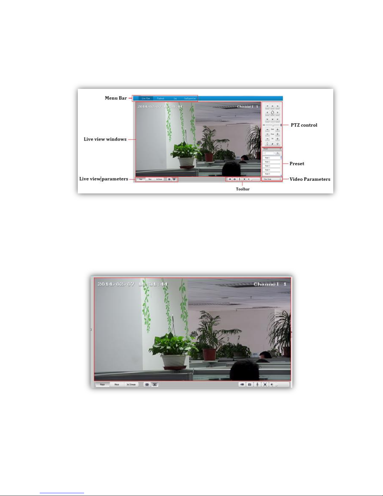
5.4 Preview
Descriptions of live view page
5.4.1 Live View
Page 20
20
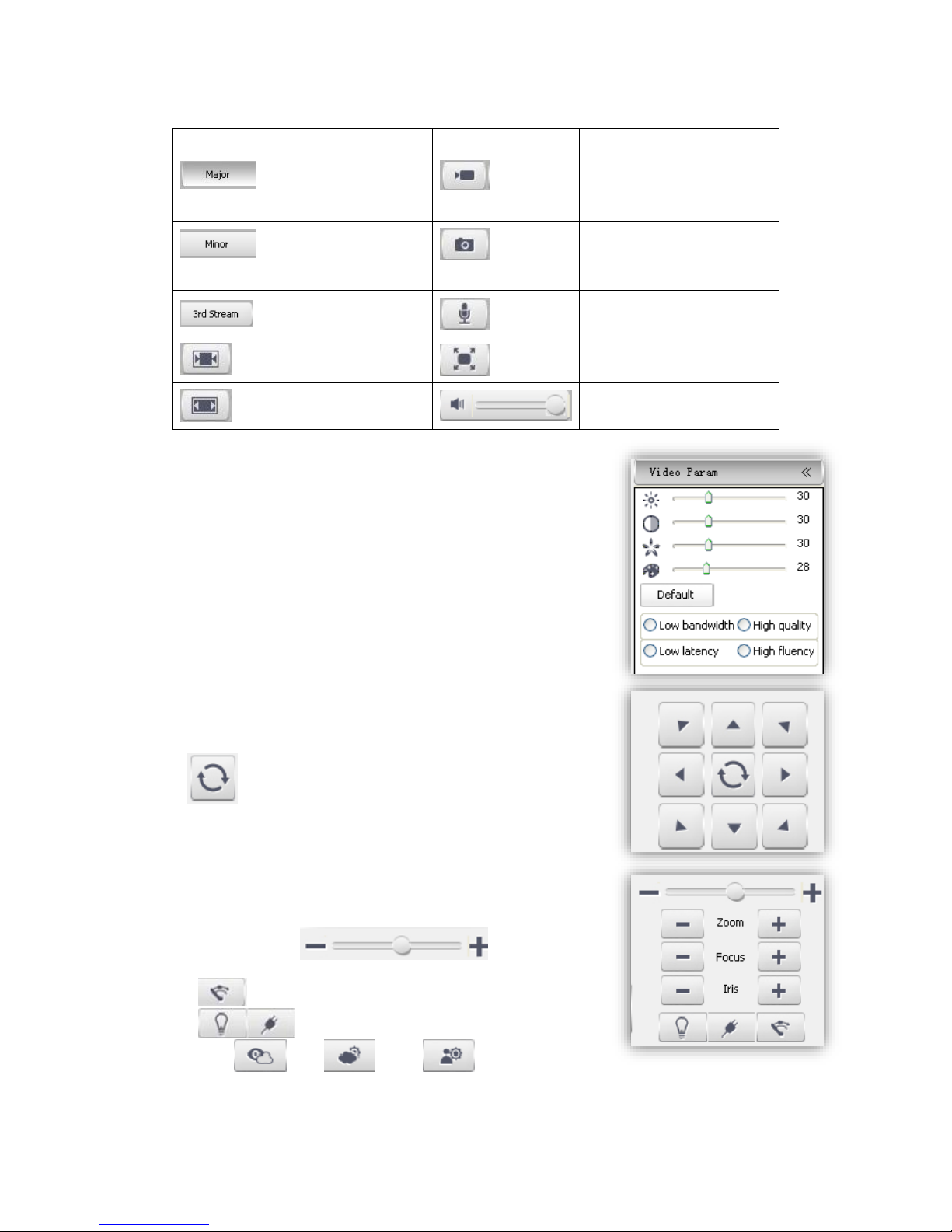
Descriptions of live view parameters and toolbar
Icon
Description
Icon
Description
Major stream
Manual recording on / off,
and default storage path is
D\NetVideoBrowser\
Minor stream
Manually capture, and
default storage path is
D\NetVideoBrowser\
Third stream
Intercom on/off
Screen lock
Full screen
Screen adapt to current
resolution
Audio on, volume adjustment
and mute
Note When stream type is【Pure Video】,audio preview is invalid.
5.4.2 Video parameter
(1)<Default> to resume the default settings.
(2)According to network situation you can choose preview mode
from <Low bandwidth>, <Low latency> to <High quality>,
<High fluency>
5.4.3 PTZ control
(1)Select rotation direction of speed dome,
enable auto scan.
(2)<Zoom>Zoom in /Zoom out
(3)<Focus> Manual Focus.
(4)<Iris>Manually adjust iris.
(5) set PTZ speed
(6) Wipper
(7) Preserved for future functions
(8) Defog: , HLC: , WDR:
Page 21
21
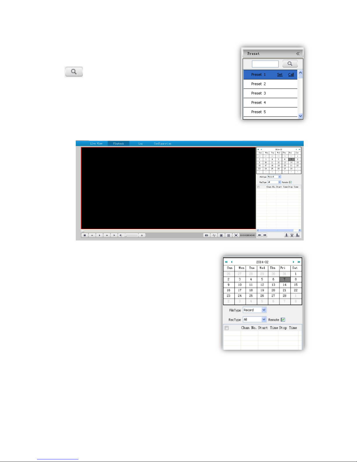
5.4.4 Preset position
Search the target preset number
<Set> Setup preset position
<Call>Call the preset position
5.5 Playback
5.5.1 Search recording files
(1)Select date in the calendar
(2) <File Type> select <Record> or <Picture>
(3)<Rec Type> Select targeted file type video/picture.
Page 22
22
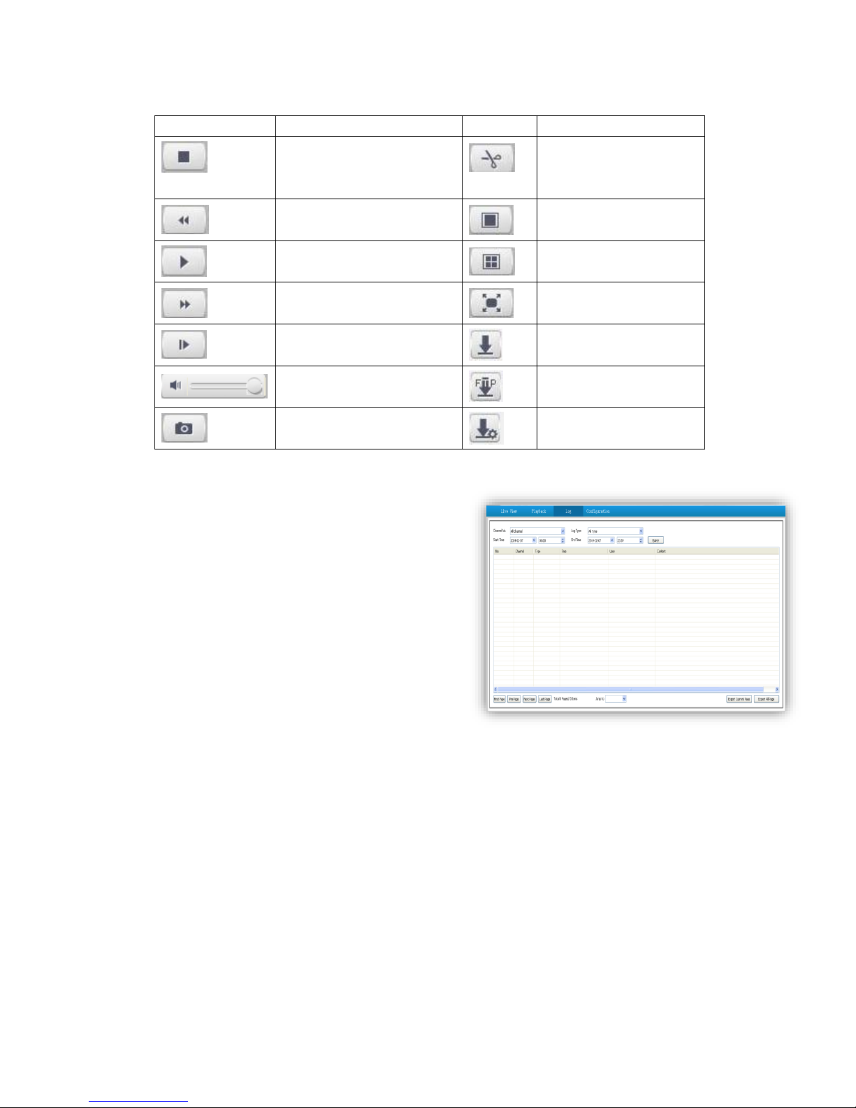
5.5.2 Descriptions of playback toolbar
con
Description
Icon
Description
Stop recording
Clip video files, and default
storage path is
D\NetVideoBrowser\
Speed down in
1/2X,1/4X,1/6X and 1/8X
Single screen
Play Playback in 4 screen at the
same time
Speed up in 2X,4X,6X and 8X
Full Screen
Playback by frame
Download recording files
Audio on, volume adjustment
and mute
Download files into FTP
server
Capture, and default storage
path is D\NetVideoBrowser\
Preview download status
5.6 Log
(1)<Channel No> Select target channel
(2) <Log type>
All/system/warning/alarm/operation/user/others
(3) <Start time> Select start date and time.
(4) <End time> Select end date and time.
(5) <Query> Get a log list.
(6) Check logs by <First page><Pre page><Next
page><Last page> and <Jump to>target page.
(7)<Export current page> to export logs, and default
save path is D\NetVideoBrowser.
(8)<Export all page> to export all the pages query,
and default save path is D\NetVideoBrowser.
Page 23
23
Chapter 6 Configuration
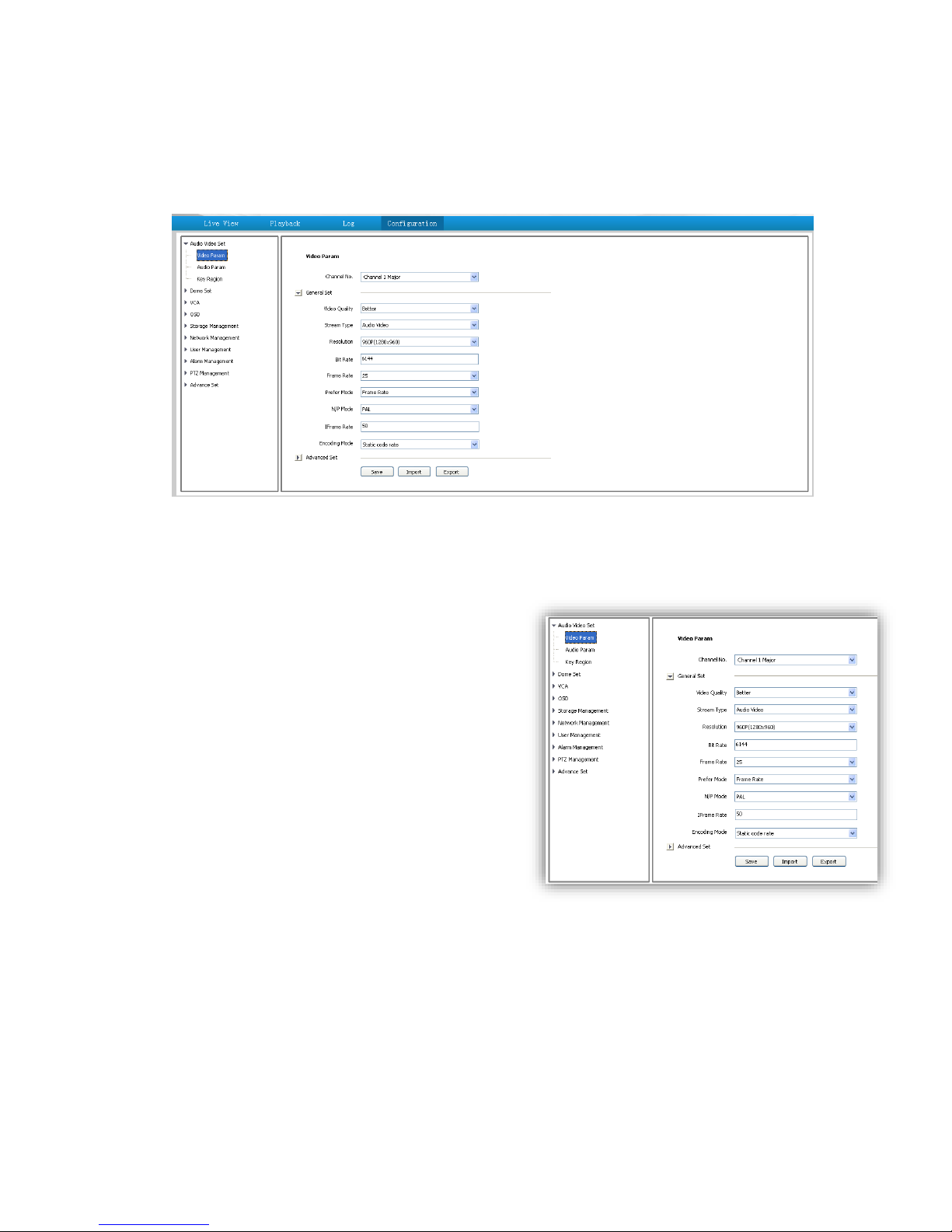
Attention: All settings will be enabled in 3 seconds after <save>.
6.1 Audio Video Set
6.1.1 Video Parameter
<Channel No.>Select the target channel
General Set
(1)<Stream Type><Audio Video>/<Pure Video>
(2)<Encoding Mode>
<Static code rate> Fix stream and bandwidth
occupation.
<Dynamic code rate> Stream will be varied to the
change of video, take up less bandwidth when there is
no change on video.
(3)<Video Quality>only be activated when choose
<Dynamic code rate> in <Encoding Mode>.
<Video
Quality><Best>,<Better>,<Good>,<Fair>,<Poor>
The better quality the more stream and bandwidth occupation.
(4)<Bit Rate> show stream rate for the video, unit is Kbps. When choose<Static code rate>, <Bit
Rate>stand for actual rate of the stream. When choose<Dynamic code rate>,<Bit Rate>show
the max stream rate, range from 32 ~ 8000Kbps.
(5)<Frame Rate> 1/5/10/15/25/30fps optional.
(6)<I Frame Rate> To set the interval time for each two I frame. (I frame is the key frame in the
video stream)
(7)<Prefer Mode>
Page 24
24
<Frame Rate> Fluency first
<Quality> Video quality first
(8)<Resolution> 4CIF/VGA/720P/960P/1080P.
(9)<N/P Mode> Select <PAL> or<NTSC>.
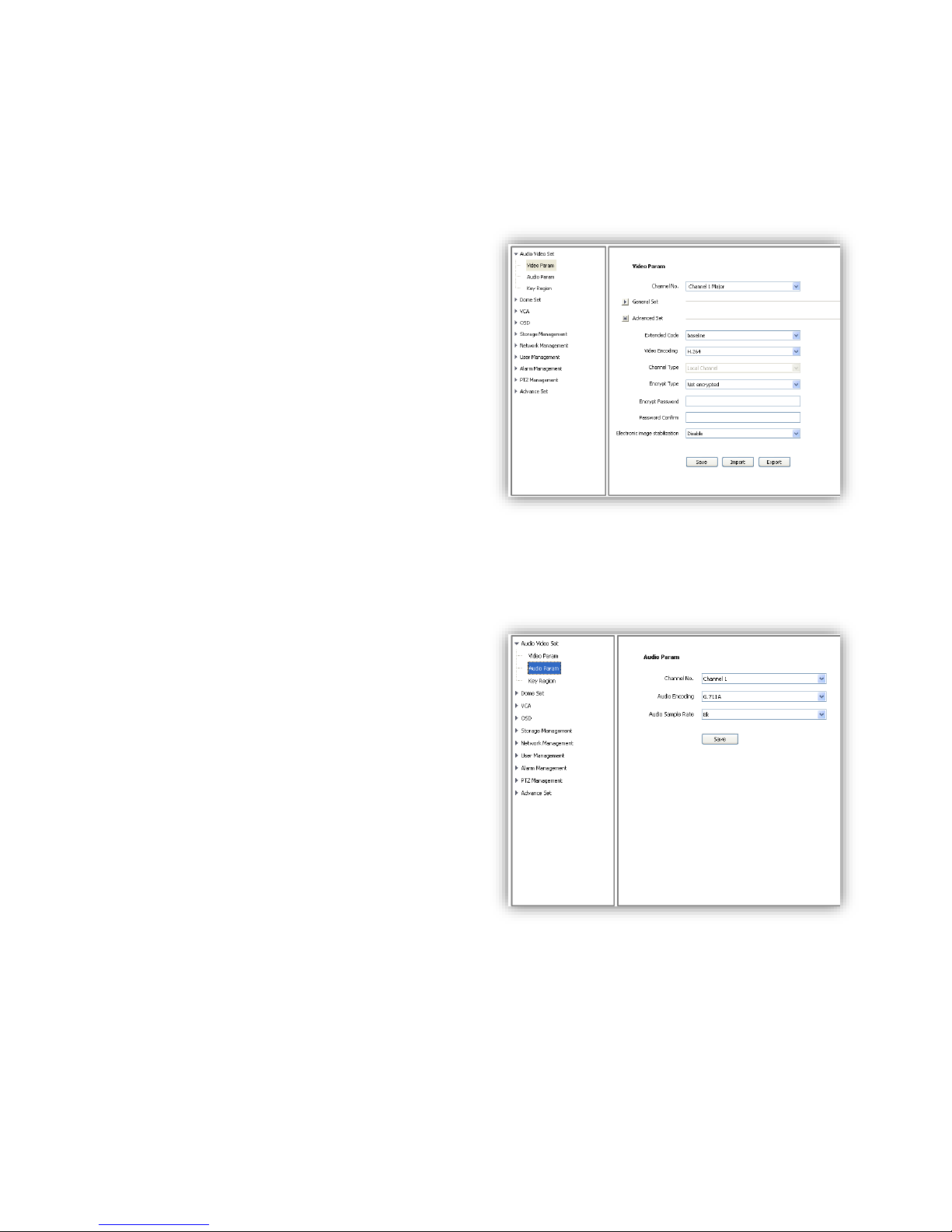
Advance Set
(1)<Video Encoding>
<H.264> and <Motion JPEG>
(2)<Extended Code>
Available when selected <H.264>, there are
<baseline>, <main profile>, <high profile> for
selection.
(3)<Encrypt Type> Add password for the
channel.
<Encrypt Password> Enter password.
<Password Confirm> Confirm the password.
Click<Save>to enable.
Video Parameter-Export
<Export> backup the configuration file, save to
D\NetVideoBrowser\VideoParam.dat as default.
Video Parameter-Import
<Import> import the backup file for parameter configuration.
Audio Parameter
(1)<Channel No.>select target audio channel.
(2)<Audio Encoding> select audio compression
type.
(3)<Audio Sample Rate>
<8k>,<32k>,<64k> optional.
(4)<Save> save and enable the setting.
Note: some models need reboot after saving the
setting.
Page 25
25
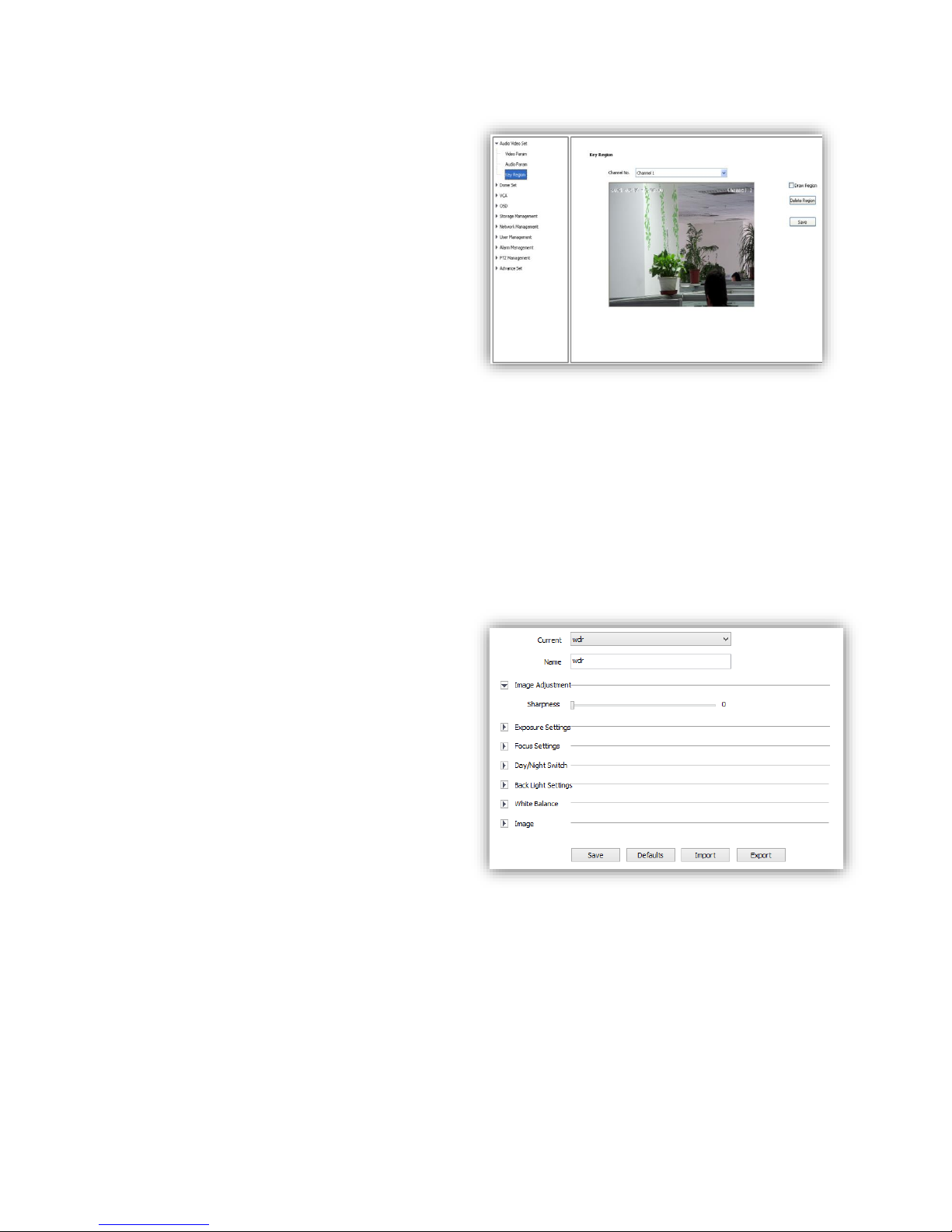
6.1.3 Key Region
<Key Region> To have better image quality
for some regions on the video, there are 4
regions settable for each video.
(1) <Draw Region>
Use the mouse to draw the key region on the
video.
(2)Click<Save> to enable.
(3) <Delete Region>
delete the drawn regions.
6.2 Dome Set
6.2.1 HD Parameter
Set video image parameter in this page.
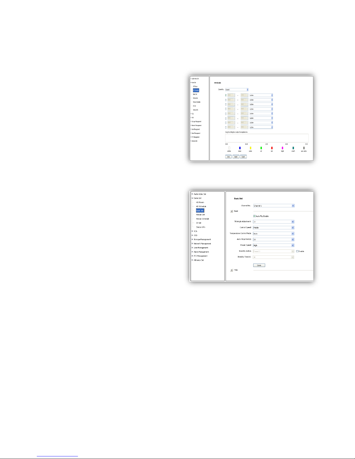
HD Param-Model
The system provides 8 video templates for
different application, all the video parameter
can only be revised and saved in the template.
(1) <Current> Select current template.
(2)<Name>show the name of the current
template, it can be revised.
HD Param-Parameter
(1)<Image Adjustment>
Sharpness range from 0 to 255.
(2)<Exposure Setting> Auto/Manual.
(3)<Focus Setting> Auto/Manual.
(4)<Day/Night Switch>
<Smart IR> On/Off
<Day/Night> Auto/Night/Day
<Sensitivity> Low/Middle/High
(5)<Backlight Settings>
<Wide Dynamic> On/Off
<Level> Low/Middle/High
(6)<White Balance ><Auto>,<Manual>and<ATW>.When selected<Manual>,there will be 2
sliding blocks to set the white balance, R stand for red gain and B stand for blue gain.
(8)<Image>
<Light Suppression> On/Off
<Defog> On/Off
<Digital Denoise> Close/Ordinary Mode/Expert Mode
<Denoise Level> range from 1~255
Page 26
26
HD Param- Defaults
Click button< Default>to recover the defaults setting for the target template.
Remark <HD Param> has Export and Import function, operation is the same as <Video Param>.
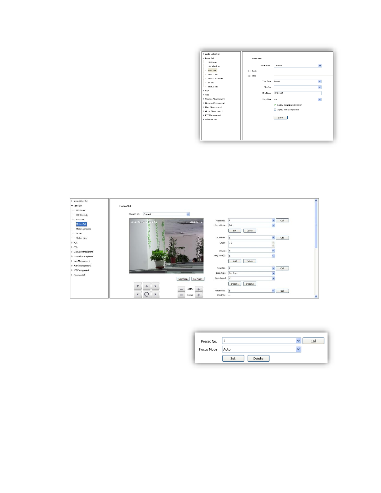
6.2.2 HD Schedule
To define different video template used for
different time period.
(1)It offers 8 different time periods, select the
check box to enable it.
(2)Select template for each time period.
(3)Length of each time period is settable. Colors
are different for different template.
(4) Click<Save>to save and enable.
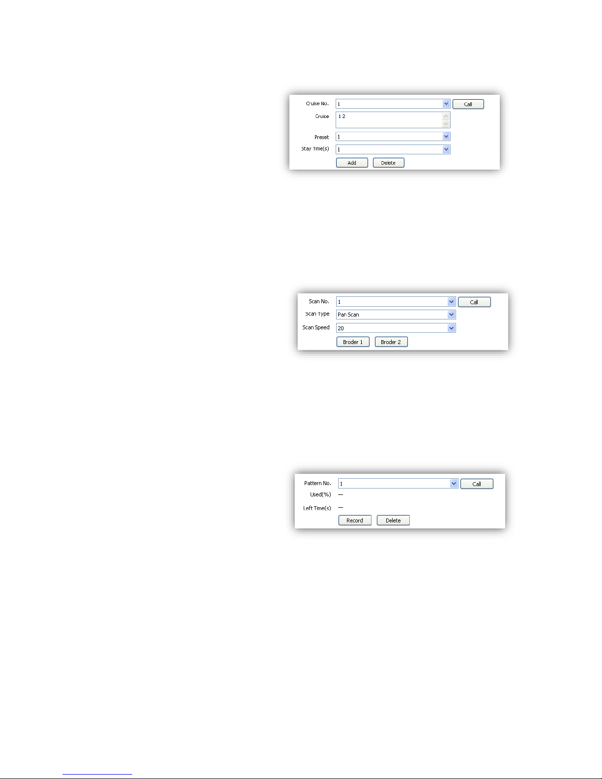
6.2.3 Basic Set
6.2.3.1 Basic
<Auto Flip Enable> Enable for 0~180°, disable
for 0~90°.
<Tilt Angle Adjustment> Set the tilt angle for
speed dome camera, range from “0”to“-11”
degree.
<Control Speed>
Set limit for the max operation speed,
high/medium/low for selection, high=240°/s,
medium=160°/s, low=80°/s.
<Auto Stop-time (s)> Set the time period for the
speed dome camera to stop PTZ movement
since the last operation. It can be set to be
5/15/30/60s.
<Preset Speed> Set the preset speed for speed dome camera, there are high/medium/low for
selection.
<Temperature Control Mode><Auto>and<OFF>
<Standby Action> It is to define the action of speed dome camera when it is idle. There are 4
options preset#1, scan#1, cruise#1 and pattern#1.
<Standby Time(s)> enable standby time setting. There are 30s,60s,300s,600s and 1800s for
selection.
<save> save and enable all the setting.
Page 27
27
6.2.3.2 Title
<Title Type> Preset, Scan, Cruise, Pattern and
Zone No.
<Title No.> Preset number range from 1-32,
Scan number range from 1-8, Cruise number
range from 1-8, Pattern number range from 18, Zone Number range from 1-8.
<Title Name>Set title name.
<Stay Time> Title display on the screen,
options 2s,/5s/10s/disappear/keep.
<Display Coordinate Direction> check to
display the movement coordinates.
<Display Title Background> check to display title background.
6.2.4 Motion Set
6.2.4.1 Preset
<Preset No.> Speed dome camera supports
220 presets, number range from 1-64 and
100-255.
<Focus Mode> Focus mode for preset can be
auto/manual.
<Set> Move to target position and press
<Set> to save as preset position.
<Delete> Delete the target number of preset position.
<Call>Speed dome camera will move to the target preset position.
Page 28
28
6.2.4.2 Cruise
<Cruise No.> Speed dome camera
supports 8 cruises, number from 1-8
<Cruise> show how many presets in the
cruise.
<Preset> Only preset number 1-64 and
100-255 are available, click <Add> to
add the preset into cruise list.
<Stay Time(S)>Set interval time
between two presets, rang from 1-60 seconds.
<Add>Add presets into cruise list.
<Delete>Remove preset from the cruise list.
<Call>Activate the speed dome to move follow the presets in cruise list.
6.2.4.3 Scan
<Scan No.>The speed dome supports 8
Scans, number from 1-8
<Scan Type>Pan Scan, Auto Scan, Frame
Scan, Random Scan, Tilt Scan and
Panorama Scan.
<Scan Speed>Set speed for Pan Scan, Auto
Scan, Tilt Scan and Panorama Scan.
<Border 1>Left border of the Scan.
<Border 2>Right border of the Scan.
<Call>Activate scan movement of the speed dome.
6.2.4.4 Pattern
<Pattern No.>The speed dome camera
supports 8 pattern tour, number range
from 1-8.
<Used(%)> Show percentage used for
operations in one pattern tour.
<Left Time(s)> Show the time remaining
in the pattern record process. (The speed dome camera supports up to 180s)
<Record> Start pattern tour recording
<Delete> Delete the target pattern.
<Call> Activate the speed dome camera to move following the pattern tour.
Page 29
29
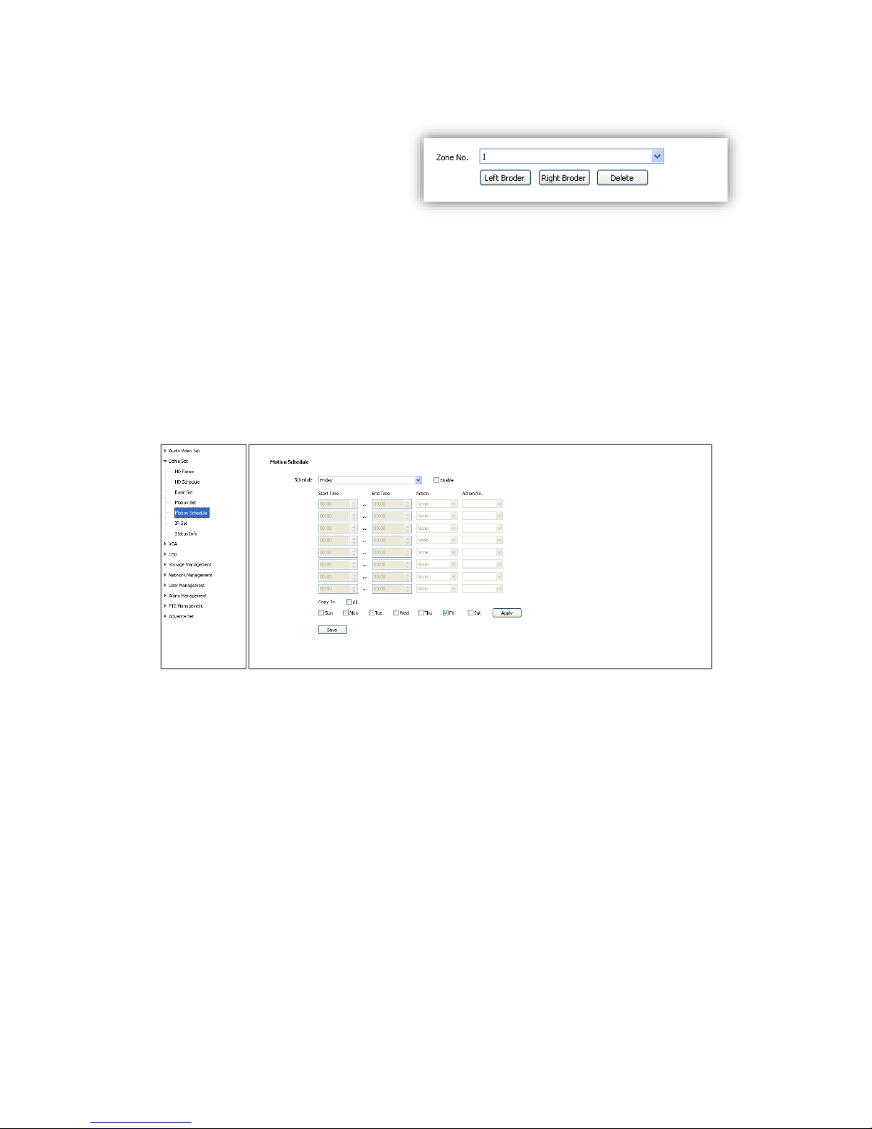
6.2.4.5 Zone No.
<Zone No.>The speed dome camera
supports 8 zones, range from 1-8.
<Left Border> Move the speed dome
camera to the target position and
set it as the left border of the zone.
<Right Border> Move the speed dome camera to the target position and
set it as the right border of the zone.
<Delete>Delete the target zone.
<Set Origin>Move the speed dome camera to the target position and set it as original point of
the coordinate.
<Set North>Move the speed dome camera to the target position and set it as north direction of
the coordinate.
6.2.5 Motion Schedule
Activate different motion (Presets, Scan, Cruise and Pattern) for different time period.
<Enable> Enable the setting.
<Start Time>Start time for the motion.
<End Time>End time for the motion.
<Action>Motion in this time period.
<Action No.>Motion number, Preset 1-8, Scan 1-4, Cruise 1-4, Pattern1-4.
<All>Enable every day in a week, including Saturday and Sunday.
<Apply>Click to copy the configuration to the selected day.
<Save>Save all the setting.
Page 30
30
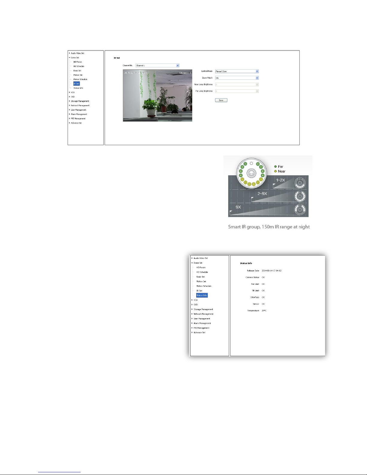
6.2.6 IR Set
<Control Mode>Auto, Manual Open, Manual Close.
<Zoom Match>When it is ON, the brightness and power
consumption of the IR LED will be matched with the camera
zooming distance automatically.
<Near Lamp Brightness> Disable zoom match, set the Near
lamp brightness level, range from 0 to 10.
<Far Lamp Brightness> Disable zoom match, set the far lamp
brightness level, range from 0 to 10.
<Save> Save all the setting.
6.2.7 Status Info
It shows current status information of speed
dome.
Page 31
31
6.3 VCA
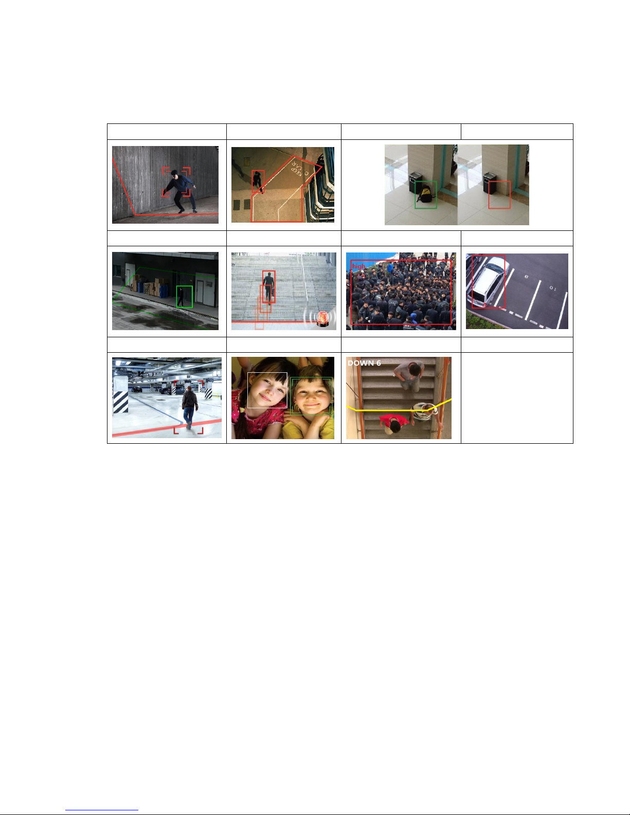
VCA(intelligent video analysis) includes 11 functions:
Tripwire
Perimeter
Items Abandon
Items Lost
Loiter
Running
Crowd
Parking
Panorama Tracking
Face Recognition
Demographics
Notes: Tripwire and Perimeter are able to activate auto-tracking.
CAUTIONS: To enable the VCA functions, please DO follow the steps:
1.Scene Set—2.Alarm Set—3.Advance—4.Cruise Set.
Specify detail operation of VCA in <Scene Set>, then setup VCA alarm schedule in <Alarm
Set>, enable <Advance>, finally setup activated time for each VCA rules in <Cruise Set>.
PLEASE DO NOT MISS ANY STEP ABOVE TO AVOID ANY FAILURE OF SETTING.
Page 32
32
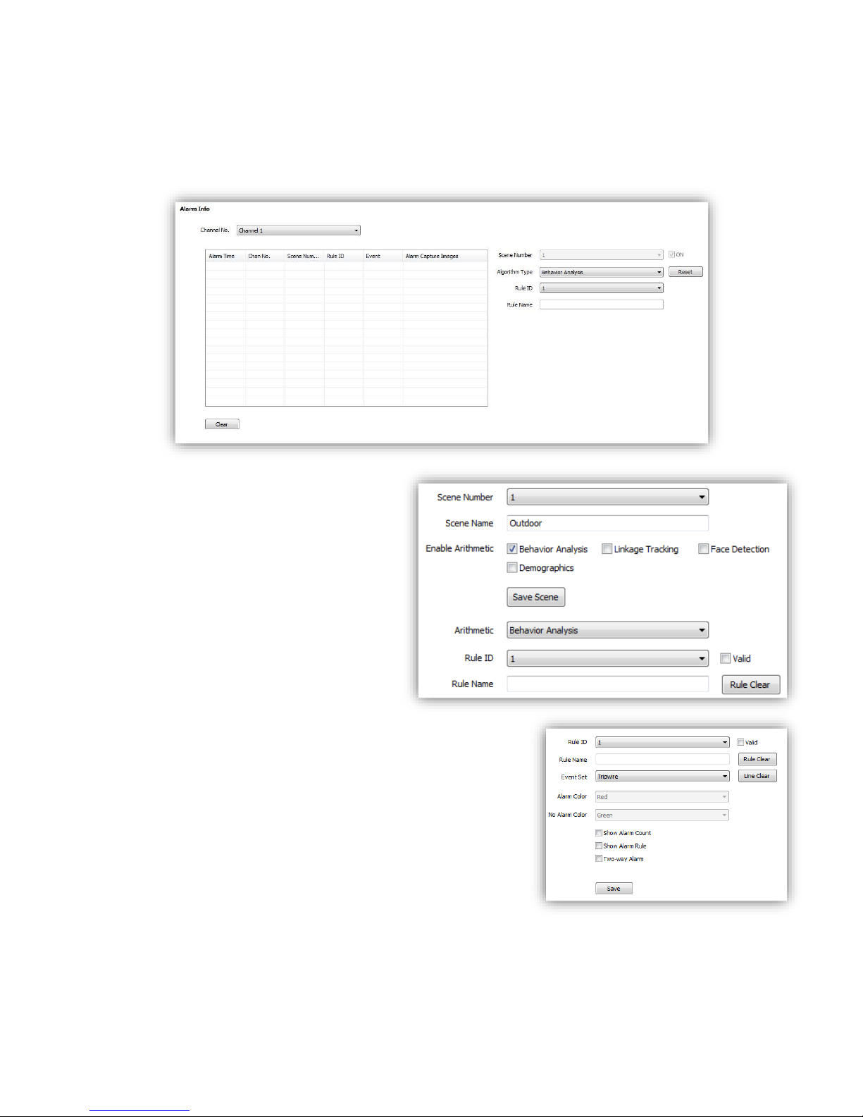
6.3.1 Alarm Info
This page is just used to display alarm info when you success to configure.
<Reset>Clear alarm numbers of the VCA rule.
<Clear>Delete all the alarm information in list.
6.3.2 Scene Set
<Behavior Analysis> check to enable
behavior analysis, including Tripwire,
Perimeter, Items Abandon, Items Lost,
Loiter, Running, Crowd, Parking.
Notes: If check <Linkage Tracking>, it
will allows Tripwire/Perimeter to
activate auto-tracking.
<Save Scene> click to activate settings.
<Rule ID> make the rule numbers for
behavior analysis. Support up to 8 rules
in the same scene at the same time.
<Valid> activate the rules and start
setting.
<Rule Name>Give a rules name(max to 16 characters).
<Rule Clear>clear current rule.
6.3.2.1 Behavior Analysis
Below are setting operation for different type of analysis
after Selected <Behavior Analysis>:
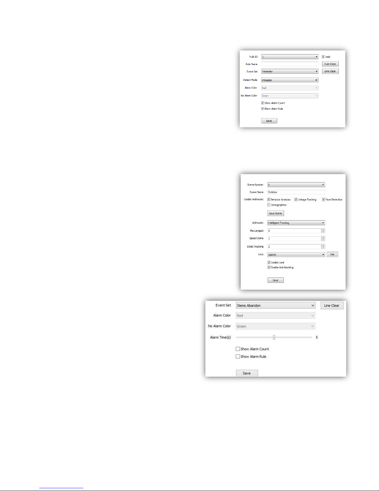
(1)Event Set --- Tripwire/Perimeter
Page 33
33
<Detect Mode> For <perimeter> detection, include
<Intrusion>/<Enter>/<Leave>.
<Intrusion> alarm when object come in/out.
<Enter> alarm when object come in.
<Leave> alarm when object go out.
<Show Alarm Count>show total alarm times.
<Show Alarm Rule>show defined tripwire/perimeter on video.
<Two-way Alarm>when selected <Tripwire>, choose the”two-
way alarm”, then two directions cross will both trigger alarm.
<Line Clear>clear current lines drawn on video.
<Rule Clear>clear current rule.
<Save>Save and enable the VCA setting.
<Linkage Tracking> or <Panorama Tracking>
Tips: <Linkage Tracking> option is only available when you
check <Behavior Analysis>
< Arithmetic > configure <Intelligent Tracking>
<The longest> Set time limitation (seconds) how long the PTZ
follow the object. And then it will go back to standby position.
<Speed Dome> Enter the value how high (meters) you install
the PTZ
<Static Tracking> Set time (seconds) when the object stay for a
while, the PTZ will go back to standby position
<Limit> Setup boarder of traking area from 4 direction. When
the object go beyond the area, PTZ will stop to follow it.
<Enable Limit>Check to activate traking area boarders
<Enable Anti-blocking>PTZ wil alarm when it is blocked
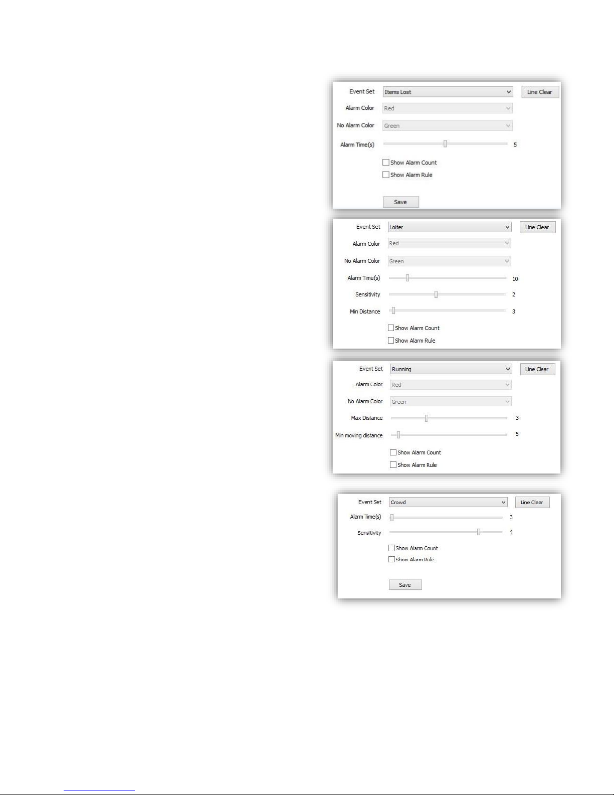
(2)Event Set ---Items Abandon
<Line Clear>remove the defined area on video.
<Alarm Time>time to activate alarm.
<Show Alarm Count>show total alarm times on
screen.
<Show Alarm Rule>show the defined area on
screen.
<Save> save to enable.
Page 34
34
(3)Event Set ---Items Lost
<Line Clear> remove the defined area on video.
<Alarm Time> time to activate alarm.
<Show Alarm Count> show total alarm times on
screen.
<Show Alarm Rule> show the defined area on
screen.
<Save> save to enable.
(4)Event Set ---Loiter
<Alarm Time> time to activate alarm.
<Sensitivity> bigger value, higher sensitivity.
<Min Distance> smaller value,higher sensitivity.
<Show Alarm Count> show total alarm times on
screen.
<Show Alarm Rule> show the defined area on
screen.
<Save> save to enable.
(5)Event Set ---Running
<Max Distance> <Min moving distance>
Set the max and min distance on screen to detect
the target object speed.
<Show Alarm Count> show total alarm times.
<Show Alarm Rule> show the defined area on
screen.
<Save> save to enable.
(6)Event Set---Crowd
<Line Clear> remove defined area.
<Alarm Time(s)> time to activate alarm.
<Sensitivity> bigger value, higher sensitivity.
<Show Alarm Count> show total alarm times.
<Show Alarm Rule> show the defined area on
screen.
<Save> save to enable.
Page 35
35
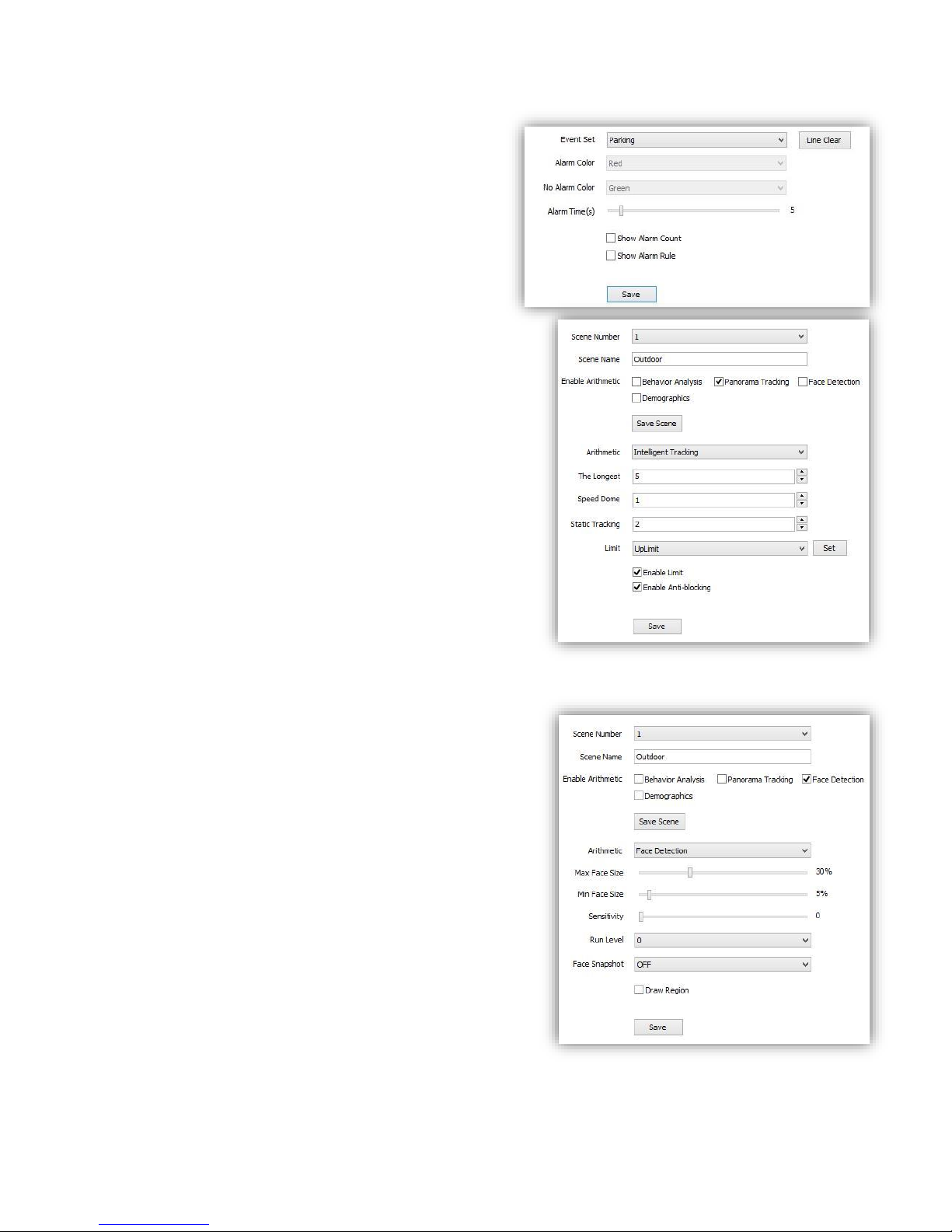
(7)Event Set --- Parking
<Line Clear> remove defined area.
<Alarm Time(s)> time to activate alarm.
<Show Alarm Count> show total alarm times.
<Show Alarm Rule> show the defined area on
screen.
<Save> save to enable.
6.3.2.2 Panorama Tracking
(1) Check to enable the target channel
(2) Select <Panorama Tracking >
(3) Click <Save Scene> to start setting.
(4) <Arithmetic> show current arithmetic.
<The longest > set the longest tracking time (S)
<Speed Dome >set the height of speed dome(this value
should be the same as actually installation height) ,3m9m is suggested .
<Static Tracking > set the time for speed dome to wait
when target object is not moving.
<Limit> set the tracking region limit on screen.
(up/down/left /right)
(5) <Enable Limit> validate the limit set.
(6) <Enable Anti-blocking> enable to detect a wider
area when target object is covered.
(7) <Save> save to enable.
6.3.2.3 Face Detection
This function will enable speed dome to recognize
people’s face and snapshot and save face picture
automatically.
(1)Check <Face Detection>
(2)Click <save scene> to start setting
(3)<Max Face Size> <Min Face Size> setup target face
size percent in target region.
(4)<Sensitivity> setup detection sensitivity.
(5)<Run level> level 0-4, bulit-in programe level, please
keep default.
(6)<Face Snapshot> ON/OFF, when ON it will capture
the detected face picutre and save.
(7)<Draw Region> click to define a region on screen,
speed dome will only detect people’s face in this region.
(8)<Save> save to enable.
Page 36
36
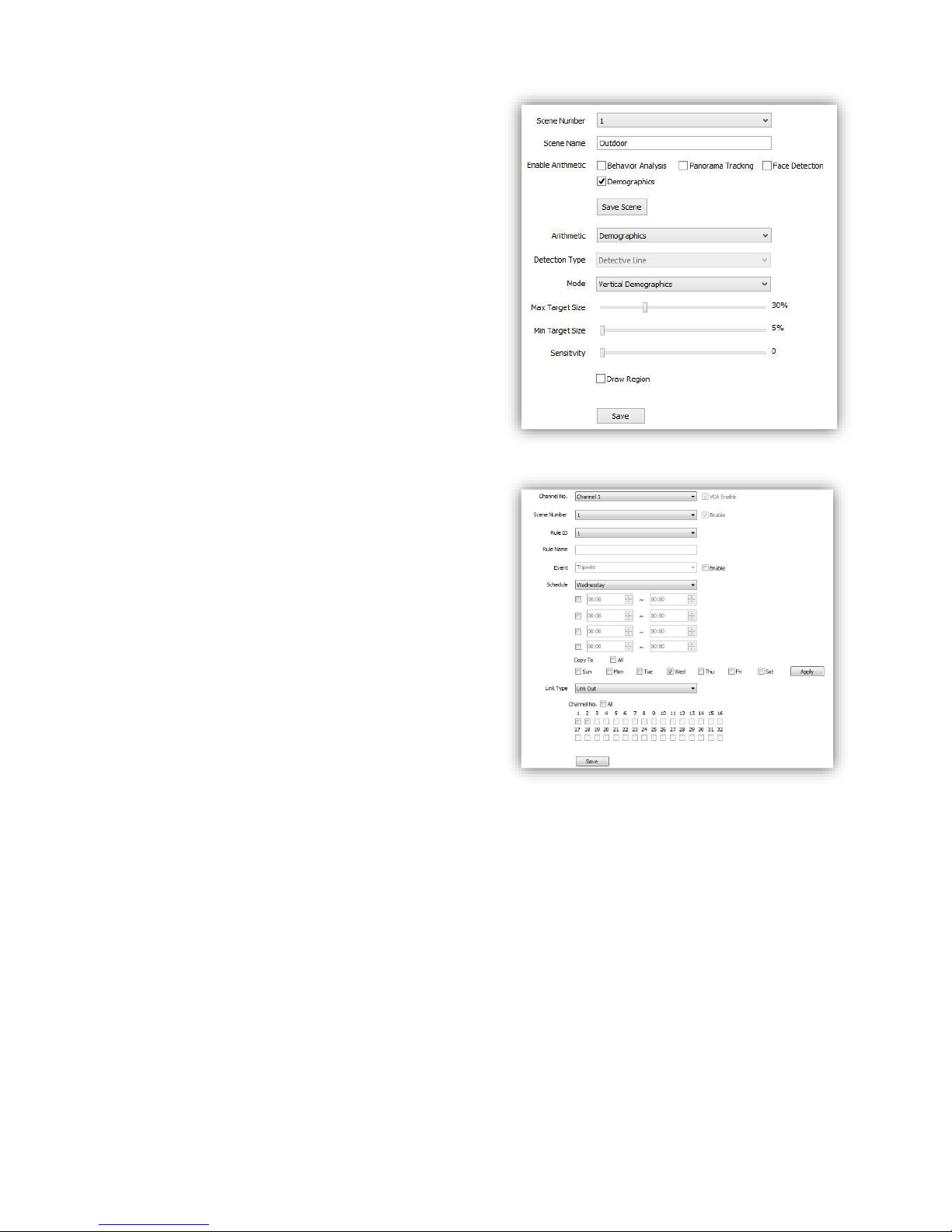
6.3.2.4 Demographics
This function will enable speed dome to count the
number of how many people cross the defined line
on screen.
(1)Check <Demographics>
(2)<Mode> choose <vertical demographics> or
<bias demographics>
(3)<Max Target Size> <Min Target Size> setup
target people size percent in target region.
(4)<Sensitivity> setup detection sensitivity.
(5)<Draw Region> check to define a region on
screen, speed dome will only count number in this
region.
(6)<Save> save to enable.
6.3.3 Alarm Set
Setup VCA activation schedule.
(1)<Channel No.> select the target channel
<VCA Enable> Indicate the VCA status of the
current channel.
(2)<Rule ID> Connected to the setup VCA rules in
<Event > When select rule ID, it will bring out
setup information of <VCA Enable>, <Rule
Name> and <Event>.
<Enable> Enable the setting of <Schedule> to
setup the day and time of the VCA activation.
(3)<Schedule> Schedule alarms. 4 time periods
selectable in a day.
<Apply> enable the setting.
(4)<Link Type>
<Link Out> alarm output.
<Link Rec> activate recording.
<Link Snap> activate snapshot.
<Save> Save to enable setting.
Page 37
37
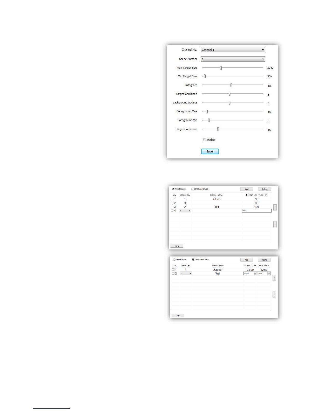
6.3.4 Advanced
(1)<Channel No.> Select target channel
(2)<Scene Number> Select target Scene No.
(3)<Max Target Size> Set upper limit how
much proportion the Object occupy on the
screen for recognition
(4)<Min Target Size> Set lower limit
Note: PLEASE KEEP THE FOLLOWING ITEMS
AS DEFAULT VALUE TO AVOID ANY ERROR.
PLEASE ASK FOR HELP OF SPECIALIST IF
REVISING NEEDED.
<Integrate>
<Target combined>
<Background Update>
<Foreground Max>
< Foreground Min>
<Target Confirmed>
(5)<Enable>
(6)<Save> save to enable.
6.3.5 Cruise Set
(1)Timed Cruise
Enable the speed dome to switch between
different defined VCA functions, time interval
range from 30~3600 seconds.
(2)Scheduled Cruise
Set valid time period for each defined VCA
functions.
Page 38
38
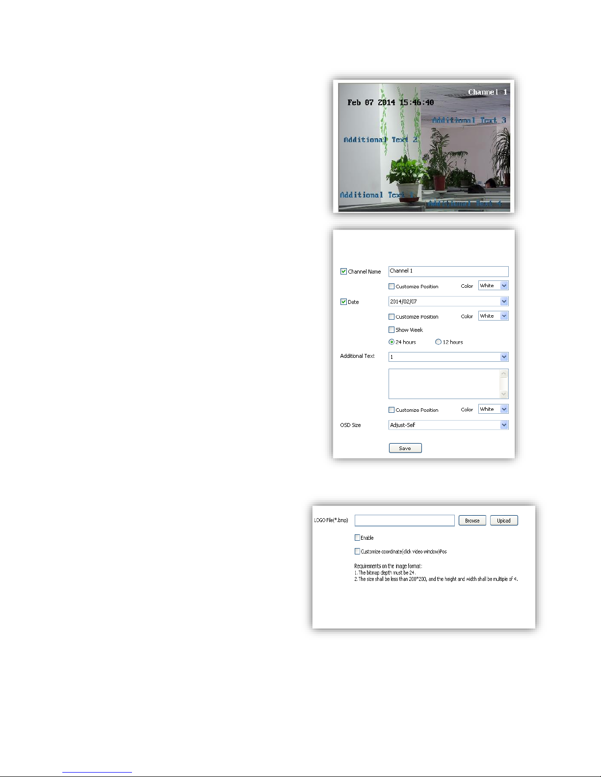
6.4 OSD
6.4.1 OSD
Channel Name
(1)<Channel Name> Input channel name, then it
will show on screen.
(2) <Customize Position> drag <Channel Name>
to the target position on screen.
(3)<Color> Choose your favorite color.
Date
(1) <Date> Display date on screen.
(2) <Show Week> Display week on screen.
(3) <Customize Position> drag <Date> to the
target position on screen.
(4)<Color> Choose your favorite color.
Additional Text
(1)<Additional Text> 5 areas available to put
additional text on the screen.
(2) <Customize Position> drag <Date> to the
target position on screen.
(3)<Color> Choose your favorite color.
OSD Size
<Adjust-Self> Edit OSD size.
<Save> Save all settings.
6.4.2 LOGO
Add LOGO picture on screen.
Notes logo picture format must
be .bmp, and must be follow the size.
<LOGO File>,<Browse> to select logo
picture, and<Upload>
Notice Device will restart after upload
(1)After restart, select<Enable> to show the
logo on screen.
(2)Enable<Customize coordinate Pos> to
put the logo on the target position on screen
where you click.
Page 39
39
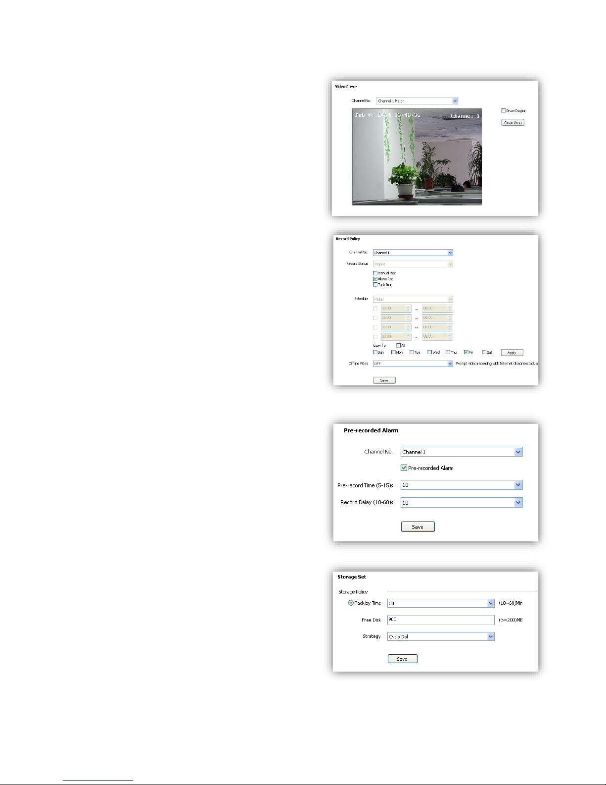
6.4.3 Video Cover
Add up to 4 cover areas on the screen.
(1)<Channel No.> Choose target channel.
(2)<Draw Region> Check to enable.
(3)Draw cover area on screen
(4)<Clean Area> Delete all cover areas.
6.5 Storage Management
6.5.1 Record Policy
Setup recording schedule.
(1)<Channel No.> Choose target channel.
(2)<Record Status> Display current record status.
(3)Select recording type(multiple-choice)
<Manual Rec> Check to start recording.
<Alarm Rec> Recording will be activated by
alarm.
<Task Rec> Timing recording, 4 time periods
settable for one day.
(4)<Offline Video> When it is ON, the device will
follow the schedule of <Task Rec> when offline.
(5)<Save> Save.
6.5.2 Pre-recorded Alarm
<Pre-recorded Alarm> record before alarm, or
continue to record after alarm.
(1)<Channel No.> Target channel.
(2)<Pre-recorded Alarm> Check to enable.
(3)<Pre-record Time> Record before alarm.
(4)<Record Delay> Continues to record after
alarm.
(5)<Save> Save.
6.5.3 Storage Set
<Pack by time> Pack the record files by time.
<Free Disk> Pack the record files by size.
<Strategy> Select how to handle the record files
when the disk is full.
<Stop Rec> Stop record new files.
<Cycle Del> Delete the earliest record files.
<Cycle Del (Except Alarm)>
Delete the earliest record files except event record
files.
Page 40
40
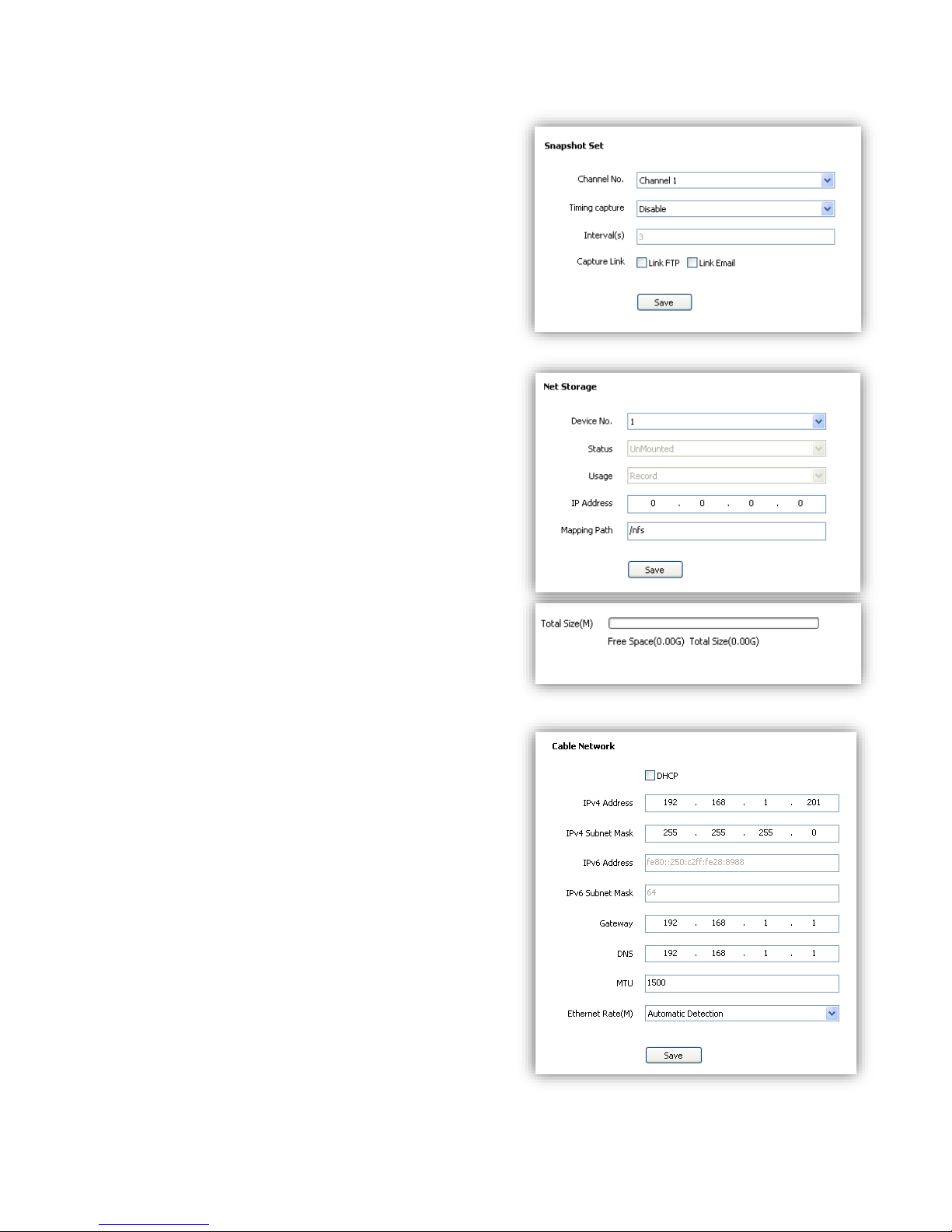
<Save>
6.5.4 Snapshot Set
(1) <Channel No.> Select target channel.
(2)<Timing capture> Enable timing capture
(3)<Interval(s)> Set how much internval times
between two snapshots.
(4)<Link FTP>snapshot and upload to FTP server.
(5)<Link Email>snapshot and send to target email.
(4)<Save>
6.5.5 Disk Information
<Initialize Disk> format the disk
6.5.6 Network Storage
(1)<Device No.> Select disk.
(2)<Status> Show current disk status information
(3)<Usage> Shows purpose of disk.
(4)<IP Address> Setup IP address of <Network
Storage>.
(5)<Mapping Path> Setup disk path of mapping.
(6)<Total Size(M)> Shows used and total capacity of
the disk.
(7)<Save>
6.6 Network Management
6.6.1 Cable Network
<DHCP> check to enable DHCP server will
automatically allocate IP address for devices.
<IPv6> Display IPV6 address and subnet mask.
<MTU> Maximum Transmission Unit, range from
500~1500, default value is 1500.
<Ethernet Rate> Select mode and rate of Ethernet
card, default mode is <Automatic Detection>, speed
unit is MB.
Notes: Devices will restart after change <Ethernet
Rate>.
Page 41
41
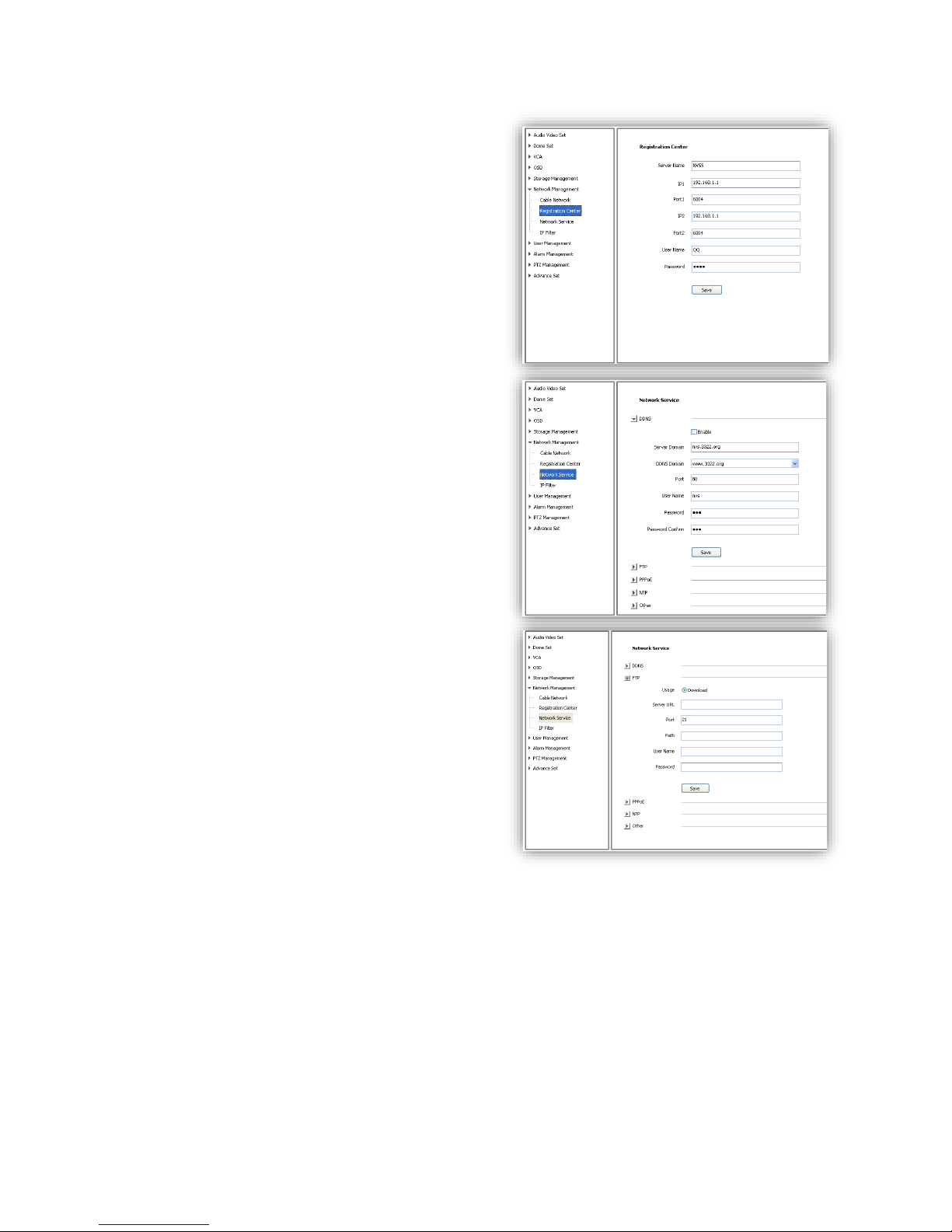
6.6.2 Registration Center
Keep same settings as what you register in DDNS
website.
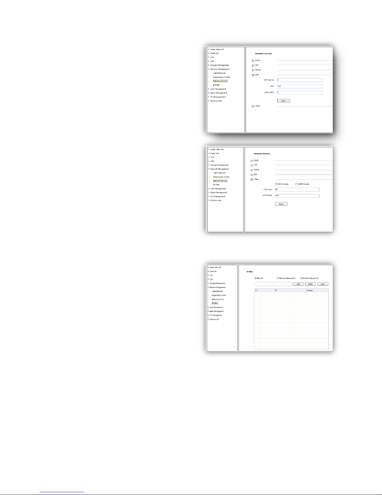
6.6.3 Network Service
DDNS
Keep same settings as what you register in DDNS
website.
FTP
Make sure to insert the memory card.
Page 42
42
PPPoE
Check to enable PPPoE function, enter User
name and confirm password.
NTP
<NTP Server> enter server address.
<Port> enter NTP server port.
<Interval> update interval.
Others
Set Http and Https port, Enable UPnP and SNMP functions.
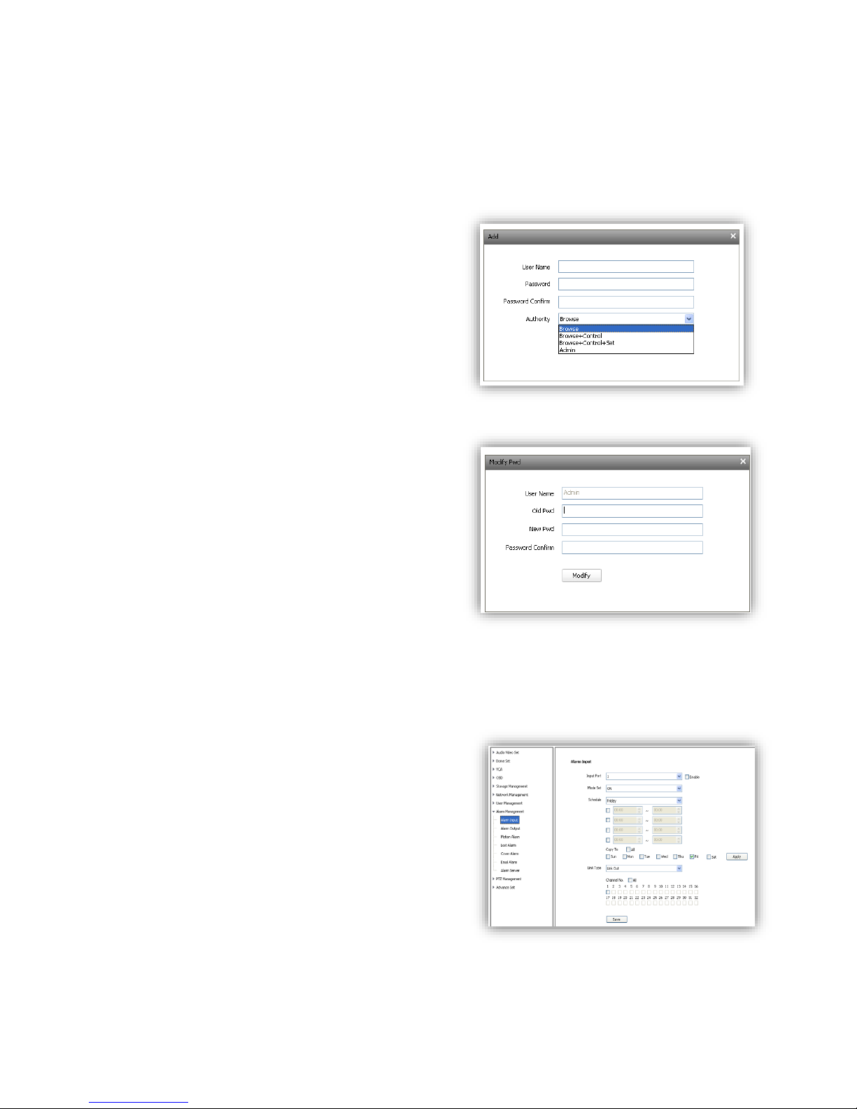
6.6.4 IP Filter
Blacklist
User want to block some IP address, select<Block the Following IPs>, input the block IP address
and<Add>,<Save>.Max to add 16 blacklist IP address.
Caution: Please don’t add your own IP address in blacklist, otherwise you will not be able to
login.
Whitelist
User want to allow only some IP address, select <Allow the Following IP>, input trusted IP
address, <Add> and <Save>. Max to 16 whitelist IP address.
Caution: Once enable the whitelist function, please make sure to add your own IP address in
whitelist, otherwise you will not be able to login the device.
Page 43
43
Cancel blacklist or whitelist
Anytime click<Allow All> and <Save> to cancel all the blacklist and whitelist.
Note: Please restart device after setup blacklist or whitelist.
6.7 User management
6.7.1 Add User
<User name> add user, only English letter and figure
are available.
<Password> only English letter and figure are
available.
<Authority>:
Browse: Can only watch the videos.
browse+ control: Watch video and control PTZ.
browse+ control+ set: Allow all operation except
user management.
Administrator: All operations available.
6.7.2 Modify password
Select the user you want to modify in the user list,
click <Modify Pwd>,input the old password, new
password, password confirmation, then
click<Modify>.
6.7.3 Delete User
Select targeted user in user list and click【Delete】
to delete.
6.8 Alarm Management
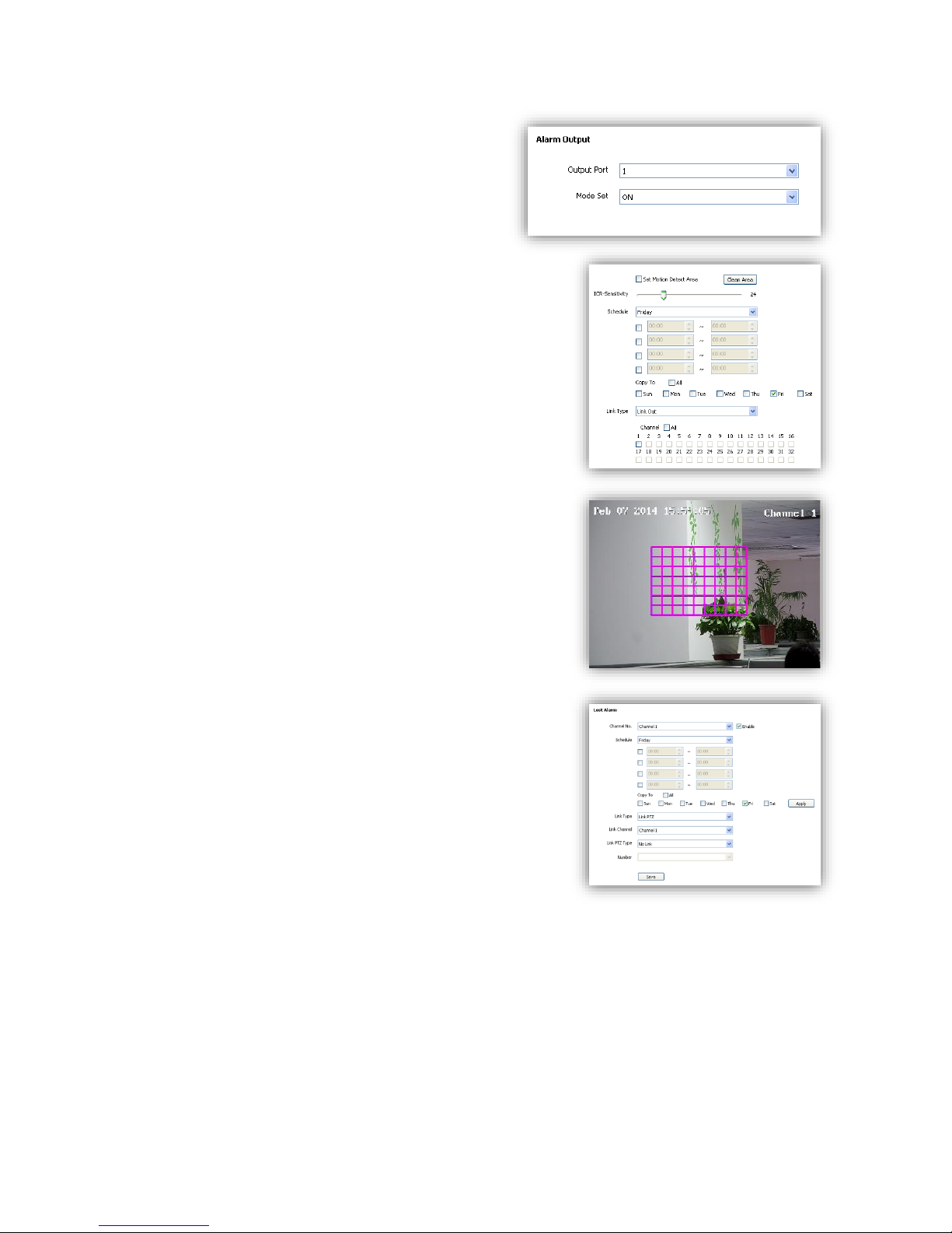
6.8.1 Alarm Input
IP Camera alarm input has port1~8, alarm mode
include closed circuit alarm and open circuit alarm.
<ON>is closed circuit alarm.
<OFF>is open circuit alarm.
<Link Out>/<Link PTZ> activate alarm device or PTZ.
Page 44
44
6.8.2 Alarm Output
Alarm output has port 1~2.
<ON>is closed circuit alarm.
<OFF>is open circuit alarm.
6.8.3 Motion Alarm
(1)<Set Motion Detection Area> Check to draw area on
screen.
(2)<Clean Area> Clean drawn area.
(3)<ICR-Sensitivity> set detection sensitivity, range from 0100, 0 means the highest sensitivity.
(4)<Schedule> setup alarm arm schedule.
(5)<Link Out> set alarm activation.
6.8.4 Lost alarm
Alarm when video lost.
(1) Check to enable lost alarm for target channel.
(2) <Schedule> Setup alarm arm schedule.
(3) <Link Type> Link PTZ/no link.
(4) <Link Channel>
(5) <Link PTZ Type> no link/preset position/pattern/auto
tour.
Page 45
45
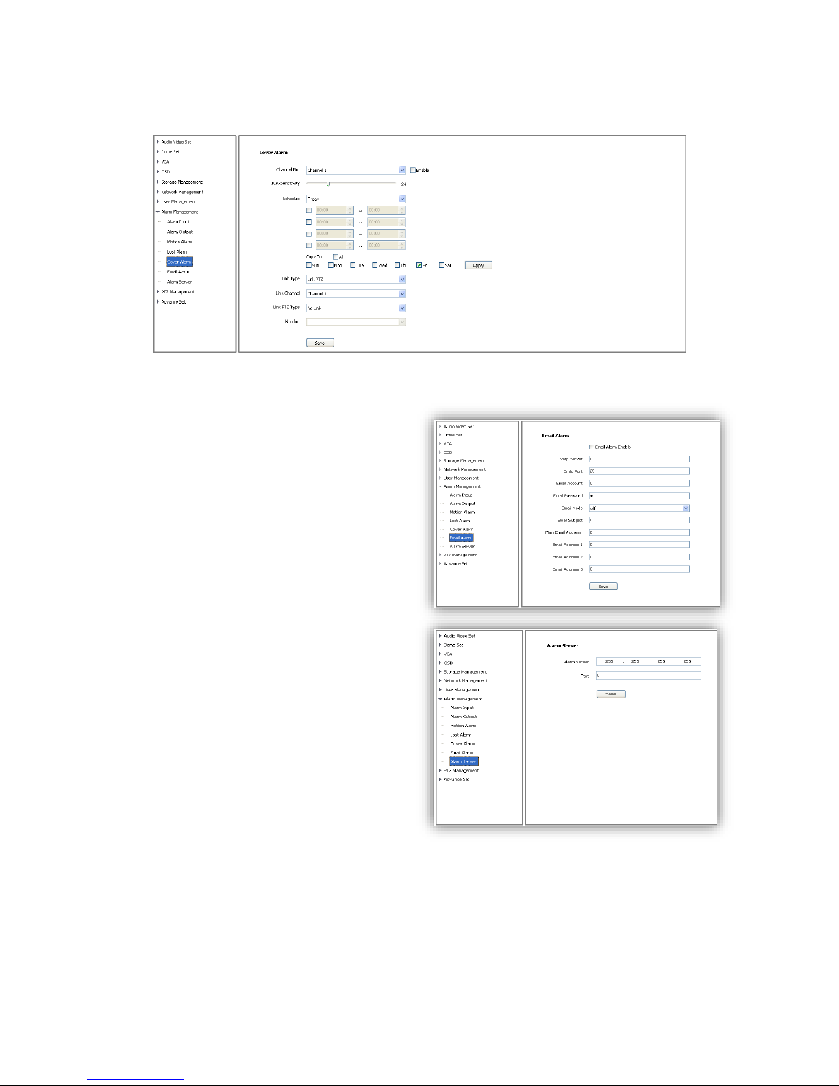
6.8.5 Cover Alarm
Alarm when camera lens is covered.
6.8.6 Email Alarm
(1)<Email Alarm Enable> check to enable
sending email after alarm.
(2)Set sending email information:
<SMTP server> <SMTP port><Email
Account><Email Password>
(3)<Email Mode>
(4)Input receive email address, support up to
4 email address.
6.8.7 Alarm Server
Set alarm server’s IP address and port
number,
Page 46
46
6.9 PTZ Management and Control
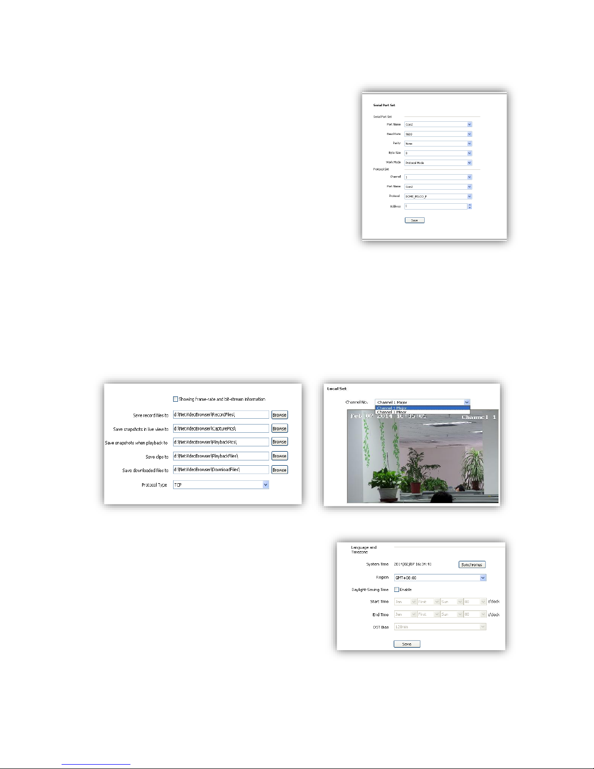
PTZ management mode: <Serial Port Set>and<Protocol
Set>
<Serial Port Set>:
<Port Name>,<Baud Rate>,<Parity>,<Byte Size>,<Work
Mode>
<Protocol Set>:
<Channel>,<Port Name>,<Protocol>,<Address>
6.10 Advance
6.10.1 Local set
(1)<Showing frame-rate and bit-stream information> check to display frame rate and bit stream
on video.
(2)Set the save path of record files, snapshot, clips and download files.
(3)<Protocol Type> TCP, UDP or multicast.
(4)IP camera has only one channel, user can choose major stream or minor stream.
6.10.2 System setting
(1)<System Time> Set time zone and time
synchronous.
(2)<SystemInformation>Display information of
CPU,Memory and FLASH.
(3)< Version Information >Display <SDK Version>,
<Kernel Version>, <Web Version> and<Factory ID>.
Page 47
47
6.10.3 System Maintenance
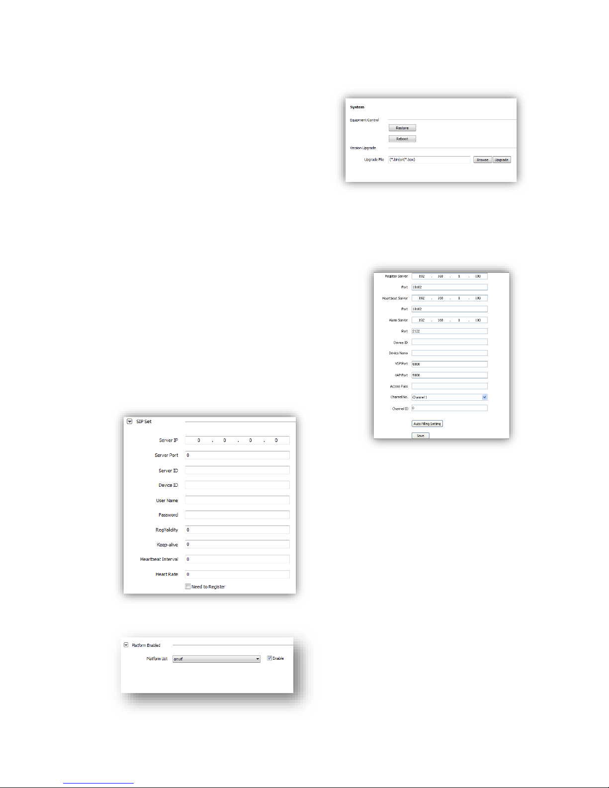
System maintenance includes <Equipment
Control>and <Version Upgrade>.
(1)<Equipment Control>
<Restore> Reset to factory default.
<Reboot> Reboot the device.
(2)<Version Upgrade> upgrade new firmware.
(firmware format: .box/.bin) Upgrade process
normally needs a few minutes until indication for
completion.
Caution: Please strictly follow the instruction by technical specialist for firmware upgrade.
6.10.4 Access Platform
PU set user can set the IP address and port number
of<Register Server>,<Heartbeat Server>,<Alarm
Server>and VSP’s port number and VAP’s port number.
<Channel No. >support<Auto Filling Setting>function.
PU set support 【SIP】protocol setting.
IP cameras support onvif V10, user can choose “enable”.
Page 48
48
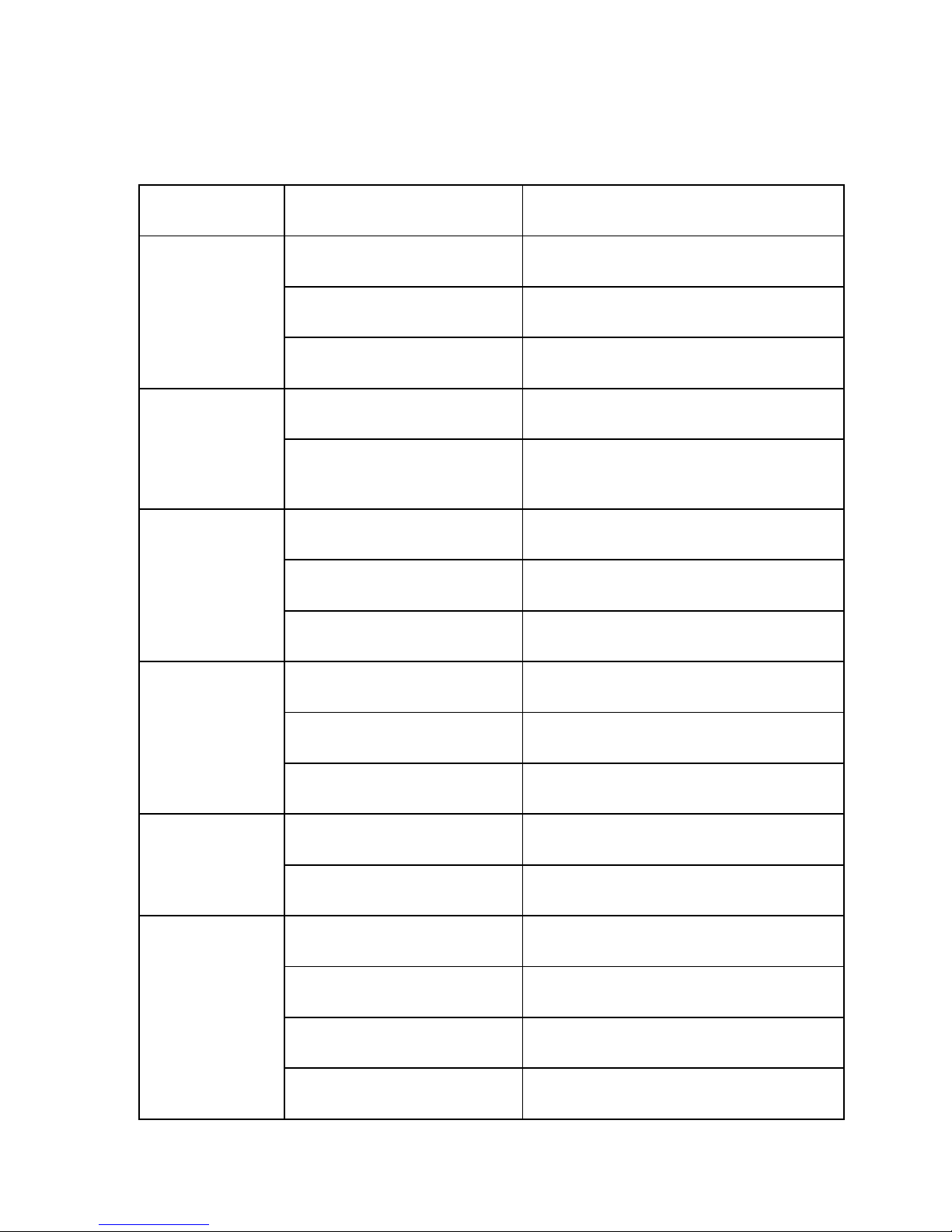
Chapter 7 Simple Problem-solving Methods
symptom
Possible causes
Solutions
Power on no action,
Power supply is damaged or not
enough power
Replace the power supply
No images,
Power cable fault
Corrected
Machine is not self
checking
Line problems
Troubleshoot line, measure IP speed dome’s
voltage
Self action properly,
but can’t ping
Network line or switch damaged
Test by IP speed dome connect to PC directly
IP speed dome’s IP address and PC’s
IP address aren’t in same network
segment
Change IP address to insure they are in the same
network segment and aren’t conflict.
Ping is working
normally, but can’t
login
User name or password error
Check user name or password
Port number error
Check port number
Login account more than limit
Disconnect other client host
No video after login
Login account more than limit
Connect video by proxy server
Camera is damaged
Check log record
Parameter setting error
Restore the default parameters
Image is not stable
IP address conflict; MAC address
conflict; broadcast storm
Check network setting
Network line problem
Check network line
Image is not stable,
delay,
PC performance isn’t enough
Check CPU utilization, reduce code stream or
resolution
Frame rate is low
Change frame rate in more than 20
The network bandwidth shortage
Replace the gigabit switches
Decoder’s performance isn’t
enough
Change decoder
Page 49

49
IP Speed dome can’t
be controlled
Serial port Settings error
Check and change serial port number to “COM2”
Protocol, Baud rate, address error
Check IP speed dome’s protocol, baud rate and
address
IP Speed dome
restart again and
again
Power supply isn’t enough, voltage
isn’t stable
Measure IP speed dome’s voltage to insure
stability
PPPOE dialing failed
Check and change dialing parameter
Camera is damaged
Replace the camera
Parameter setting error
Restore the default parameters
Page 50

50
Chapter 8 After-sales Service
The HD Network IR speed dome products, the company offers one-year warranty. Product
warranty, the company provides a free service, but if any of the following circumstances, is charged
fee for material costs work:
Do not operate in accordance with the provisions of the manual
The speed dome damage caused by a case of the lightning strikes, fires and irresistible natural
disasters;
Matching problems arising from poor design to other manufacturers products cause damage;
Company statement
As we continue to introduce new technologies and product specifications are subject to
change without prior notice.
Appendix I Lightning and Surge
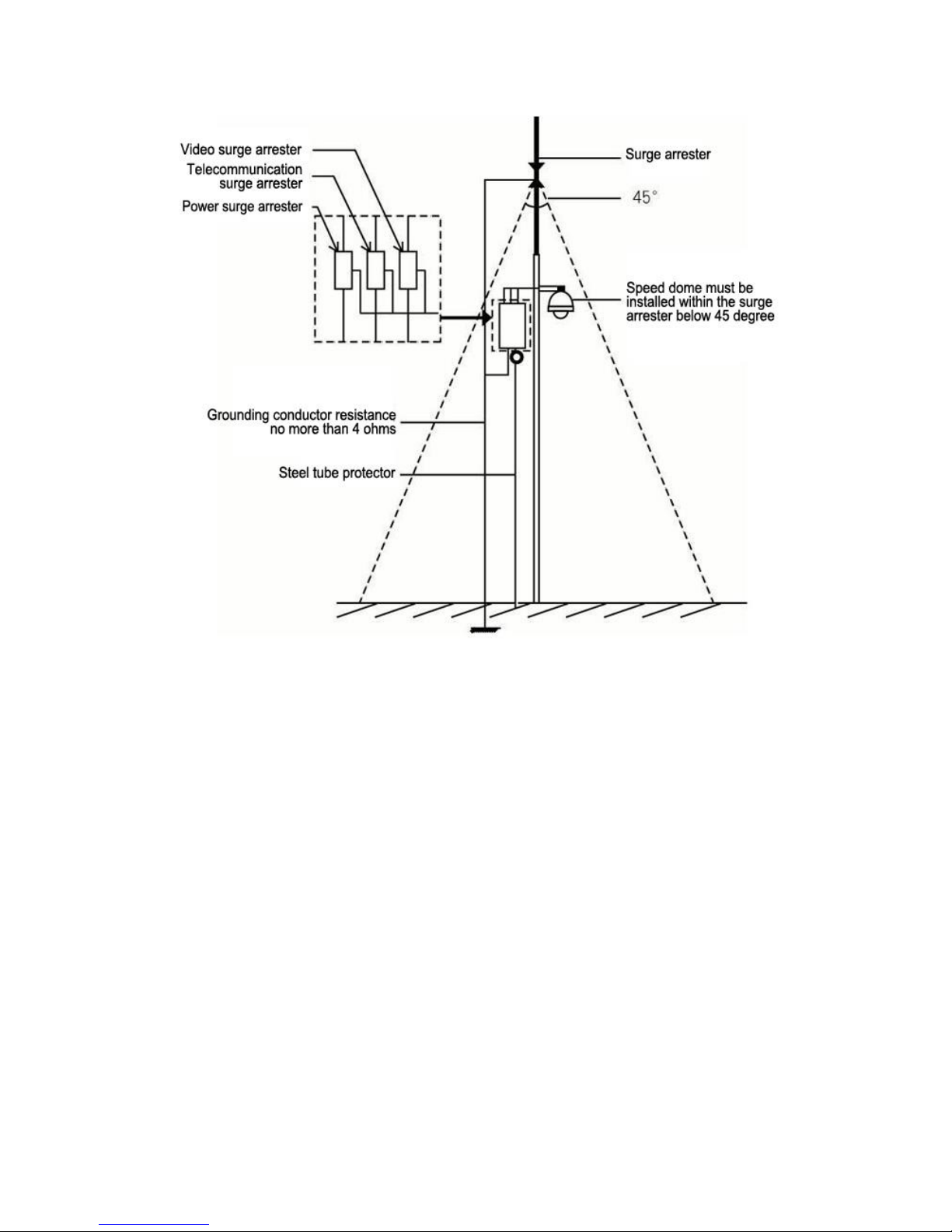
Outdoor Dome Camera need to consider lightening, anti-surge, on the premise of ensuring
electrical safety, may take the following measures:
Signal transmission lines and high voltage equipment or high voltage cables must be at least
Page 51

51
50 meters distance between;
Try to choose outdoor wiring along the eaves line;
For open field must be sealed steel tubes buried cabling, grounding and steel pipe, the
absolute prohibition of the use of overhead wiring;
In areas of severe thunderstorm or high-voltage area (such as high-voltage substations),
lightning protection equipment, as well as for additional installed power must be taken
measures such as installing lightning rods
Outdoor lightning protection and grounding design of devices and circuits must be combined
with building mine requires unified consideration and in accordance with the requirements
of the relevant national standards, industry standards;
System must be equipotential earthing. Earthing system anti-interference must be met and
the dual requirements of electrical safety, and shall not be mixed with strong power network
neutral wire shorted or separately when grounding, grounding impedance less than 4 ohms,
ground wire cut-area must be not greater than 25mm2 lines shorted
Page 52
52
Page 53
53
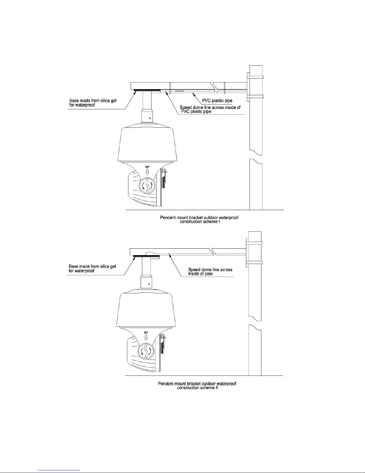
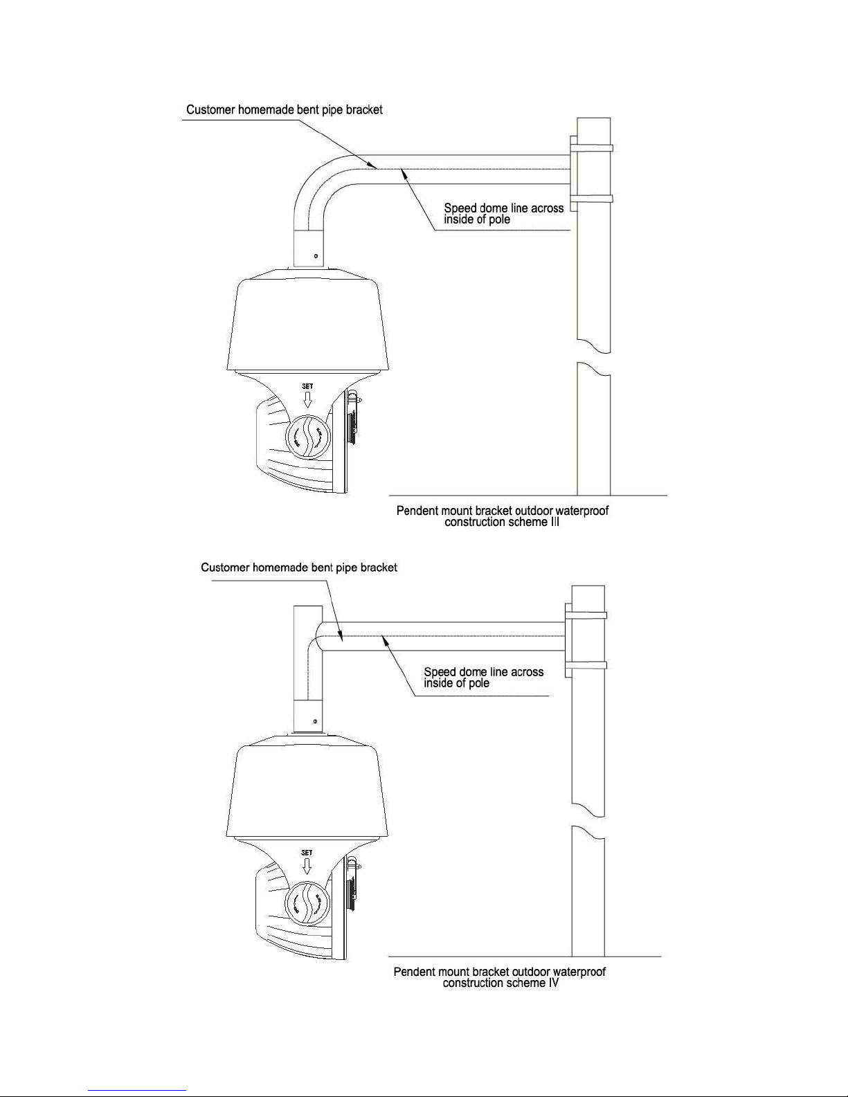
Appendix II::Hoisting construction Guide
Page 54
54
 Loading...