

Tiandy H.264 POE SERIES, Lite H.265 SERIES, Standard H.264 SERIES, Standard H.265 SERIES, Enhanced H.265 SERIES User Manual

Net Video Recorder
User Manual
1

Introduction
Channel
HDD Number
series
4/8/16 ch
1/2/4 HDD
H.264 POE
4/8/16/32 ch
1/2/4/8 HDD
Standard H.264
20/40/80 ch
2/4/8 HDD
Standard H.265
40/80/160 ch
8/16 front-loaded HDD
Enhanced H.265
5/10/20 ch
1 HDD
Lite H.265
10/20 ch
2HDD
Lite H.265
Thank you for purchasing our products and please contact us at any time if you
have any question or need.
Applicable Model
This Manual is applicable to the following models:
2

Disclaimer
This Manual may contain inaccuracies, unconformities in product function operation
or misprints. Our company will update the contents of this Manual according to the
enhancement and change of product functions and regularly improve and update the
software and hardware products described in this Manual. The updated information
will be reflected in the latest version of this Manual without notice.
Our company continues to adopt new technologies and performs real-time product
update, so no further notification is performed if any upgrade.
This Manual is for reference only and it cannot guarantee that the products described
are all the same as real objects; for the actual application, please in kind prevail.
The parts, components and accessories mentioned in this Manual do not represent
the standard configuration of device, and the detailed configuration shall be subject
to the packing list.
All the characters, tables and picture information in this Manual are protected by the
relevant laws of the state and cannot be used without permission.
About Default 1
Factory default administrator account of device: admin
Factory default administrator password of device: admin
Factory default IP address of device: 192.168.1.3
Sign Description
The descriptions for the signs presented in this Manual are shown below:
3

Sign
Description
It indicates that there is a moderate or low-level potential
danger which may result in minor or moderate injury if it
cannot be avoided.
It indicates that there is a potential risk that the device damage,
loss of data, performance degradation or unpredictable results
may be caused if these texts are ignored.
It indicates the additional information of text and the
emphasis and supplement for the text.
4

Contents
1、Overview of Product Functions ...................................................................................................... 10
2、Operation Instructions ..................................................................................................................... 15
2.1、Introduction and Description of Front Panel ........................................................... 15
2.2、Introduction and Description of Back Panel ........................................................... 20
2.3、Mouse Operation Description ................................................................................. 25
3、Installation and Connection ............................................................................................................ 27
3.1、Installation Precautions ........................................................................................... 27
3.2、Hard Disk Installation ............................................................................................. 28
3.2.1、Hard Disk Capacity Calculation Method .................................................................. 29
3.2.2、Installation Steps of Hard Disk ................................................................................. 29
4、Local Configuration and Operation ................................................................................................ 32
4.1、Startup and Shutdown ............................................................................................. 32
4.1.1、Startup ....................................................................................................................... 32
4.1.2、Shutdown .................................................................................................................. 33
4.2、Startup Guide .......................................................................................................... 34
4.3、Channel Management ............................................................................................. 41
4.3.1、Shortcut Bar Channel Adding ................................................................................... 41
4.3.2、General Digital Channel Adding ............................................................................... 43
4.3.3、POE Camera Adding ................................................................................................. 47
4.3.4、Plug-and-play Setting ................................................................................................ 48
4.3.5、Configuration Management ...................................................................................... 49
4.3.6、IPC Central Management .......................................................................................... 50
5

4.3.7、POE Power Information ............................................................................................ 54
4.3.8、Encoding Setting ....................................................................................................... 54
4.3.9、Video Setting ............................................................................................................ 57
4.3.10、OSD Superposition Parameter Setting .................................................................... 62
4.3.11、Motion Detection .................................................................................................... 64
4.3.12、Mask Alarm ............................................................................................................ 66
4.3.13、Alarm Input Setting ................................................................................................. 66
4.3.14、Video Loss Alarm Setting ....................................................................................... 68
4.3.15、PTZ Control ............................................................................................................ 68
4.4、Preview ................................................................................................................... 69
4.4.1、Preview Interface Status ............................................................................................ 69
4.4.2、Descriptions for Right-click Menu of Mouse ........................................................... 70
4.4.3、Super Taskbar Menu Description.............................................................................. 74
4.4.4、Easy Operation of Preview ....................................................................................... 75
4.4.5、Preview Parameter Setting ........................................................................................ 77
4.4.6、Information Prompt on Preview Interface ................................................................. 80
4.4.7、Audio Preview and Talkback .................................................................................... 82
4.4.8、One-key Returning to Preview Interface ................................................................... 82
4.5、PTZ Control ............................................................................................................ 83
4.5.1、PTZ Parameter Setting .............................................................................................. 83
4.5.2、PTZ Control Operation ............................................................................................. 83
4.5.3、Preset, Cruise and Track Setting and Call ................................................................. 85
4.5.4、USB Keyboard Control PTZ ..................................................................................... 87
6

4.6、Recording ................................................................................................................ 88
4.6.1、Recording Guide ....................................................................................................... 88
4.6.2、Recording Setting ...................................................................................................... 91
4.6.3、Recording .................................................................................................................. 95
4.6.4、Diskgroup Setting ..................................................................................................... 95
4.6.5、Snapshot Setting ........................................................................................................ 98
4.6.6、Rebuilding Index ....................................................................................................... 99
4.7、Playback ................................................................................................................ 101
4.7.1、Instant Playback ...................................................................................................... 101
4.7.2、Playback Interface Description ............................................................................... 101
4.7.3、Normal Playback ..................................................................................................... 102
4.7.4、Event Playback ........................................................................................................ 103
4.7.5、Tag Playback ........................................................................................................... 104
4.7.6、Smart Playback ....................................................................................................... 106
4.7.7、Time-phased Playback ............................................................................................ 110
4.7.8、Picture Playback ...................................................................................................... 111
4.7.9、External File Playback ............................................................................................ 112
4.7.10、Playback by Log Information ............................................................................... 113
4.7.11、Auxiliary Function of Playback ............................................................................ 115
4.8、Backup .................................................................................................................. 117
4.9、System Setting ...................................................................................................... 122
4.9.1、General Setting ........................................................................................................ 122
4.9.2、Network Setting ...................................................................................................... 124
7

4.9.3、Disk Management ................................................................................................... 131
4.9.4、Array Management ................................................................................................. 138
4.9.5、Hot-spare Setting..................................................................................................... 141
4.9.6、Configuration Management .................................................................................... 145
4.9.7、Log Management .................................................................................................... 147
4.9.8、Routine Maintenance .............................................................................................. 148
4.9.9、System Information ................................................................................................. 153
4.9.10、Other Setting ......................................................................................................... 157
4.10、Alarm Setting ...................................................................................................... 159
4.10.1、Alarm Input ........................................................................................................... 159
4.10.2、Alarm Output ........................................................................................................ 161
4.10.3、Alarm Host ............................................................................................................ 162
4.10.4、Manual Alarm ....................................................................................................... 163
4.10.5、Manual Alarm Clearing ........................................................................................ 164
4.11、User Management ............................................................................................... 165
4.11.1、User Adding .......................................................................................................... 165
4.11.2、User Permission Configuration ............................................................................. 167
4.11.3、User Editing .......................................................................................................... 168
4.11.4、Device Locking ..................................................................................................... 173
4.12、VCA .................................................................................................................... 173
4.13、Mobile Monitoring .............................................................................................. 179
5、WEB Access ................................................................................................................................. 180
5.1、Introduction ........................................................................................................... 180
8

5.2、Login ..................................................................................................................... 180
5.3、Preview ................................................................................................................. 181
5.4、Playback ................................................................................................................ 184
5.5、Log ........................................................................................................................ 186
5.6、Configuration ........................................................................................................ 187
6、Internet Keyboard ......................................................................................................................... 188
6.1、Keyboard Installation ............................................................................................ 188
6.2、Button Description ................................................................................................ 188
A Liquid crystal display: .................................................................................................................. 188
B Key button area: ............................................................................................................................ 189
C DVR control button area: ............................................................................................................. 189
D Extended function button area: ................................................................................................... 191
E Lens control button area: ............................................................................................................. 191
F Control device type selection and matrix unauthorized control button area: ......................... 191
G Three-dimension vector gear shift rocker .................................................................................. 192
Appendix 1 Hard Disk Capacity Calculation Reference ..................................................................... 192
Appendix 2 Answer to Common Fault ............................................................................................... 193
Appendix 3 Maintenance Description................................................................................................. 195
9

1、Overview of Product Functions
Introduce the main functional characteristics which need to be known by users when using
the NVR.
Basic Functions
Support the access of network device; the webcam, webdome and network video
server as well as the third-party webcam can be accessed.
Support the standard Onvif protocol.
Support the dual-stream preview in each channel.
Support the adjustable coding parameters, including resolution, frame rate, bitrate,
image quality and other parameters in each channel.
Support the general and alarm, customization 1, customization 2 and other intelligent
recording template parameters in each channel.
Support to add IP channel rapidly.
Local Monitoring
Support the VGA and HDMI display.
Support the multi-screen video preview.
Support the 1/3/4/6/8/9/10/13/16/20A/20B/25/32/36/40/64 screen preview at most.
Support the quitmenu operation of preview.
Support the local and front-terminal VCA.
Support the video motion detection, video loss detection, video mask detection and
port alarm detection.
10

Support a variety of mainstream PTZ control protocols and support the presetting bit,
cruising path, track setting and call.
Hard Disk File Management
Support the hard disk SMART information display.
Support the bad track detection.
Support the hard disk attribute setting: redundancy, read only, read-write and
backup.
Support the hibernation of hard disk.
Support disk group quota; disk group can be divided or different video save spaces
can be allocated for different channels.
The devices of NR2020-E8, NR2040-E8, NR2080-E8, NR2080-E16, NR2160-E16,
NR2020-S8, NR2040- S8 and NR2080- S8 models support the disk array.
Recording and Playback
The recording trigger mode includes: manual, timing and port alarms, motion
detection alarm, detection or port alarm, detection and port alarms, video loss alarm,
video mask alarm, VCA alarm and other alarm trigger recordings.
Support the pre-recording and delay of link recordings of all alarm types.
Support to inquire the recording file according to the general/event.
Support the local redundancy video.
Support the locking and unlocking of recording file.
11

4 recording time periods can be set every day and the recording trigger modes of
different time periods can be set independently.
Support the holiday plan.
Support to inquire videos according to the channel numer, recording type, starting
and ending time, file type and other items.
Support the general playback, event playback, tag playback, external file playback,
intelligent playback, picture playback, time sharing playback and other playback
modes.
Support the video snapshot function and support to distinguish different types of
videos by different colors.
Support the functions of pause, fast playback, slow playback, advancing 30S,
backing 30S, steping forward, steping back, stop, previous day, next day and
positioning by dragging mouse.
Support to zoom in and out the playback time shaft by mouse wheel.
Support the electronic amplification of any playback area.
Support the reverse playback function of recording file.
16-channel and above devices support at most 16-channel synchronous playback.
Data Backup
Support to back up videos, pictures and other data through USB device.
Support batch backup according to the range and type of file.
Support the video playback clip backup.
12

Support the rapid backup by channel and time.
Support the management and maintenance of backup device.
Alarm and Exception Management
Support the arming time setting of alarm input/output.
Support the video loss, motion detection, video mask, port, VCA, detection or port,
detection and port and other alarm detections. Various alarms can be linked to
single-screen display, character plan, voice prompt, email sending and trigger alarm
output and also can trigger any channel video.
Support the disk full, no disk, disk read-write errors, illegal access, IP address
conflict, MAC address conflict, no available redundant disk, network disconnection,
hot standby exception, array exception, disk overload, recording exception, disk
smart exception and other exception detections; a variety of exceptions can trigger
the screen prompt, voice warning, uploading center, mail alarm and port alarm.
Support the software watchdog reboot when system runs abnormally.
Other Local Functions
For the users with five-level permission, the administrator can create multiple
operating users and set their permissions and the permissions can be refined to the
channel.
Complete operation, alarm, exception and information log record and retrieval.
Support the manual alarm triggering and clearing.
Support the import/export operation of configuration information of device.
Network Function
13

Support the TCP/IP protocol stack and support PPPoE, DHCP, DNS, DDNS, NTP,
SADP, NFS, HTTPS and other protocols.
WEB server is embedded.
Support the unicast and multicast and support TCP, UDP and RTP protocols during
unicast.
Support the remote search, playback, download, locking and unlocking of recording
file.
Support to remotely obtain and configure parameters and support to remotely export
and import device parameters.
Support to remotely obtain the operation status of device, system log and alarm
status.
Support the remote formatting of disk, program upgrade, restaring and other system
maintenance operations.
Support to perform the alarm port extension by alarm host.
Support the remote manual triggering and recording stopping.
Support remote manual triggering and alarm output stopping.
Support the remote PTZ control.
Support the voice talkback or voice broadcast.
Development Support
Provide the SDK software development kit under Windows and Linux systems.
Provide the application software source code of demonstration.
14

Provide the development support and development training service of application
No.
Type
Name
Description
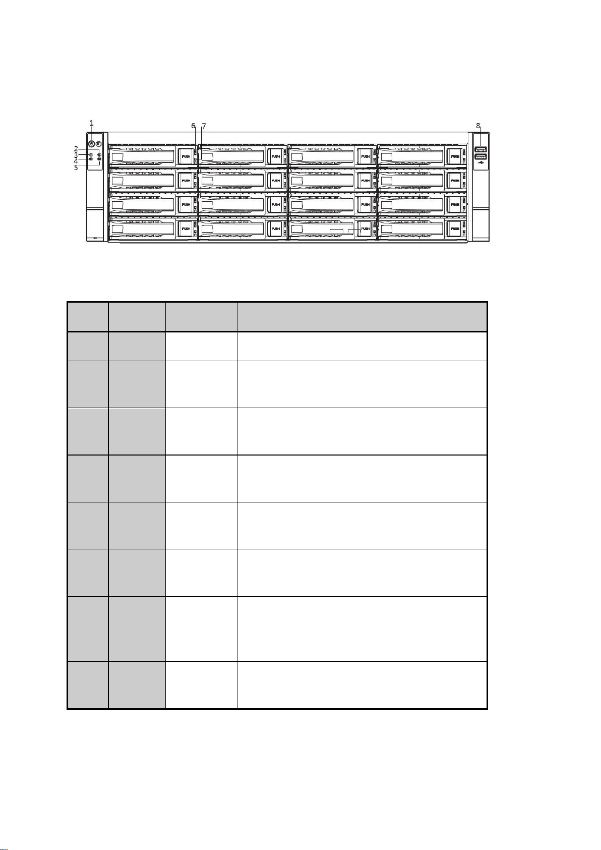
1
Status
lamp
PWR
It is the power indicator which is on when the
device link power is in an energized status.
HDD
It is the hard disk work indicator which flashes
when the device reads and writes the disk.
system.
Description:
The main functions supported by our NVR are listed in the product function part and
the functions of different models are different due to different positions and
configurations, so please in kind prevail.
2、Operation Instructions
Introduce the parts and accessories which must be known by users before using NVR:
front and back panels, mouse as well as how to operate the device by using these parts and
accessories.
2.1、Introduction and Description of Front Panel
Introduce the descriptions for front panel buttons and indicators.
The panels of PSE series NVR and standard series NVR (2/4 HDD) are shown below:
The functions of front panel are shown below:
15

NET
It is the network status lamp which flashes under
the network communication status.
2
Interface
USB
interface
It can connect with the mouse, U disk, mobile hard
disk and other external devices.
No.
Type
Name
Description
1
Status
lamp
PWR
It is the power indicator which is on when the
device link power is in an energized status.
HDD
It is the hard disk work indicator which flashes
when the device reads and writes the disk.
NET
It is the network status lamp which flashes under
the network communication status.
The front panels of NR40 standard series NVR (1/2/4 HDD) and NR50 standard series NVR
(1 HDD) are shown below:
The functions of front panel status lamps of NR40 standard series NVR (1/2/4 HDD) and
NR50 standard series NVR (1 HDD) are shown below:
The front panels of NR40 standard series NVR (8 HDD) and NR50 standard series NVR (8
HDD) are shown below:
16

No.
Type
Name
Description
1
Status
lamp
Ready
It is the host-ready indicator which flashes when
the device is power on and works normally.
Status
The status lamp is on under the control of remote
control.
Alarm
It is the alarm status lamp which flashes under the
alarm status.
Hard disk
It is the hard disk work indicator which flashes
when the device reads and writes the disk.
Network
It is the network status lamp which flashes under
the network communication status.
Communi
cation
It is on under the normal communication status of
front panel and mainboard.
1—16
It is the front 16-channel dual-color status
indicator, the blue lamp is on when there is a
video and the yellow lamp is on during recording.
2
Button
Power
switch
Turn on/turn off NVR.
The functions of front panel status lamps of NR40 standard series NVR (8 HDD) and NR50
standard series NVR (8 HDD) are shown below:
17

3
Button
Number
button
It is used to select the displayed channel screen
under the preview status and the displayed channel
screen corresponds to the number button pressed;
It is used to input numbers and characters under
the editing status.
4
Button
Function
button
It is used to conduct preset point call, zoom
control, focus control, iris control, light control
and wiper control under the PTZ status;
It is used to conduct manual recording, video
playback, main and auxiliary interfaces switching,
one-key alarm removing and main menu calling.
5
Button
Direction
button
It is used to move the action box of menu setting
item and select the data of menu setting item
under the menu mode;
It is used to accelerate and decelerate the play
control and select previous/next file, previous/next
event, previous/next tag or previous/next day
under the playback status.
6
Interface
USB
interface
It can be connected with mouse, U disk, mobile
hard disk and other external devices.
The front panel of NR50 enhanced series NVR (8 HDD) is shown below:
18
The front panel of NR50 enhanced series NVR (16 HDD) is shown below:
No.
Type
Name
Description
1
Button
POWER
On-off button + power indicator.
2
Status
lamp
Alarm lamp
It bright when the device works abnormally.
3
Status
lamp
Run lamp
It bright when the device works normally.
4
Status
lamp
LAN1
It is the status lamp of network card 1 which
flashes under the network communication status.
5
Status
lamp
LAN2
It is the status lamp of network card 2 which
flashes under the network communication status.
6
Status
lamp
Disk error
indicator
It becomes red when the disk is abnormal.
7
Status
lamp
Disk
operation
indicator
It becomes green and flashes when the disk
works normally.
8
Interface
USB
Interface
It can be connected with mouse, U disk, mobile
hard disk and other external devices.
The functions of front panel status lamps of NR50 enhanced series NVR (8 HDD) and NR50
enhanced series NVR (16 HDD) are shown below:
19
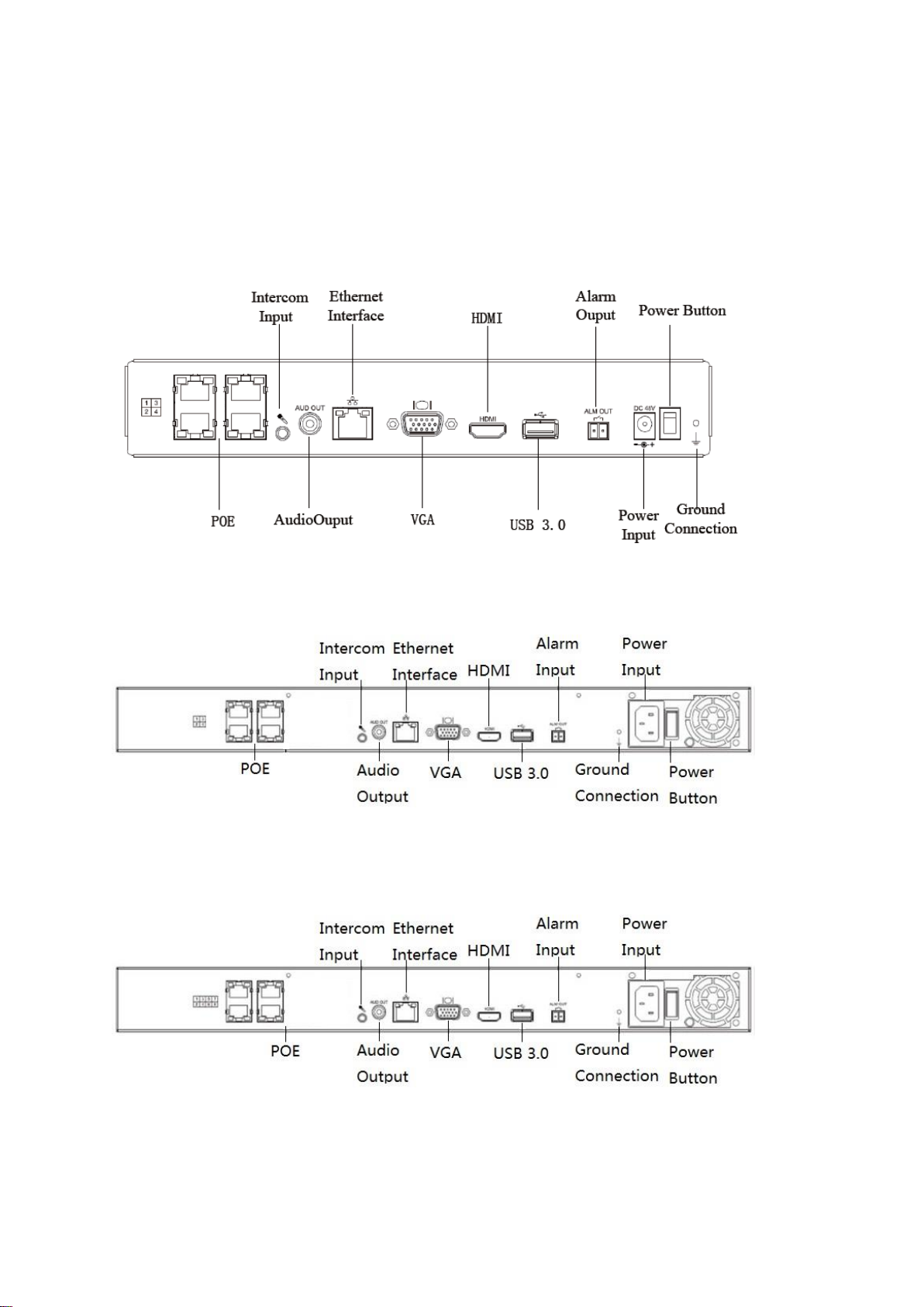
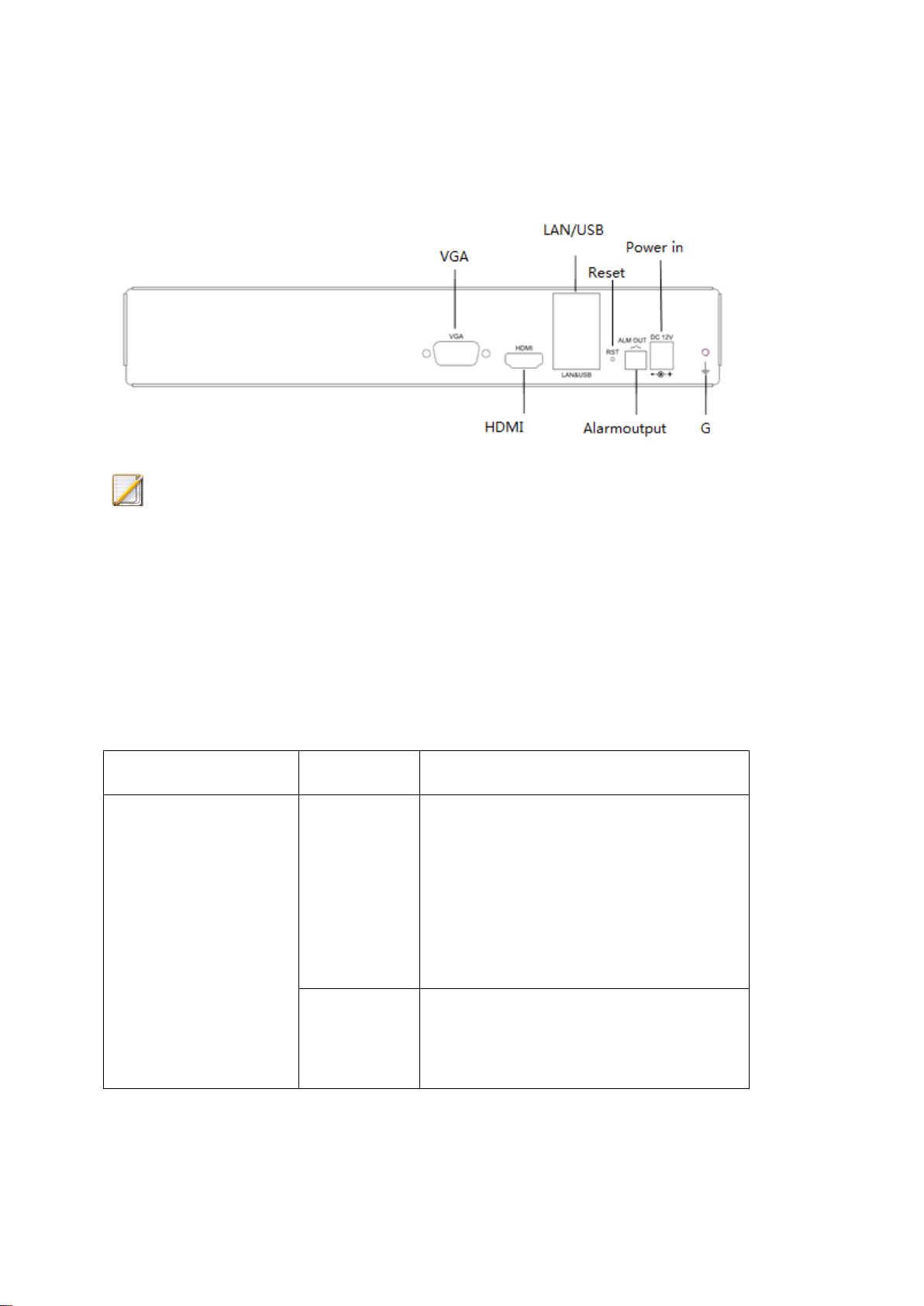
2.2、Introduction and Description of Back Panel
Introduce the descriptions for back panel and interface of device.
The back panel interface of PSE series NVR (4-channel 1 HDD) is shown below:
The back panel interface of PSE series NVR (4-channel 2 HDD) is shown below:
The back panel interface of PSE series NVR (8-channel 2 HDD and 16-channel 2 HDD) is
shown below:
The back panel interface of PSE series NVR (16-channel 4-disk) is shown below:
20
The back panel interface of NR40 standard series NVR (4/8-channel 1 HDD) is shown
below:
The back panel interface of NR40 standard series NVR (4-channel 2 HDD and 8-channel 2
HDD) is shown below:
21
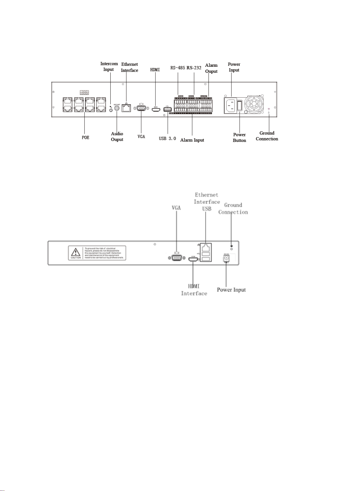
The back panel interface of NR40 standard series NVR (16-channel 2 HDD and 16-channel 4
HDD) is shown below:
The back panel interface of NR40 standard series NVR (16-channel 8 HDD and 32-channel 8
HDD) is shown below:
22

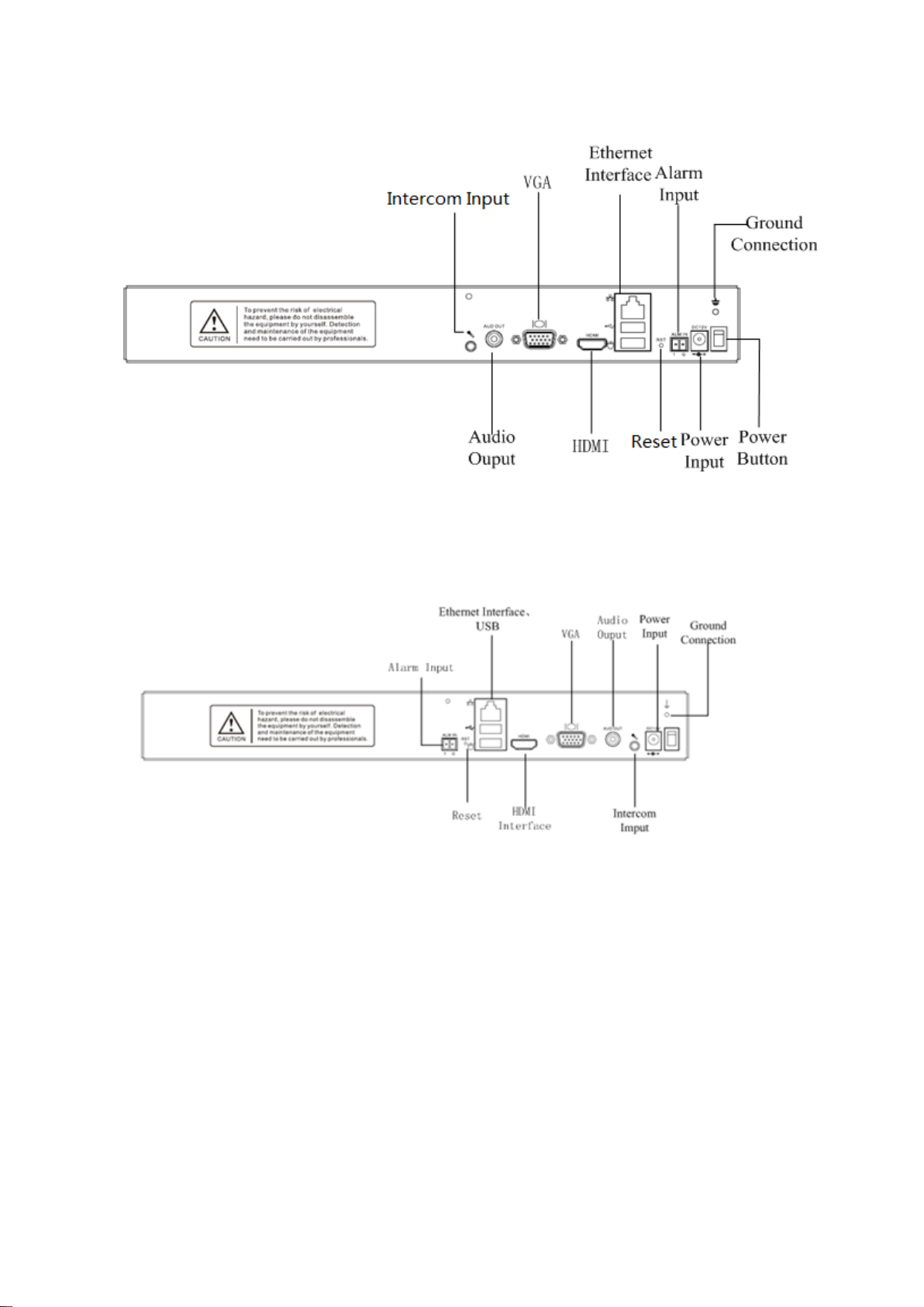
The back panel interface of NR50 standard series NVR (20-channel and 40-channel 4 HDD)
is shown below:
The back panel interface of NR50 standard series NVR (20-channel 2 HDD) is shown below:
23
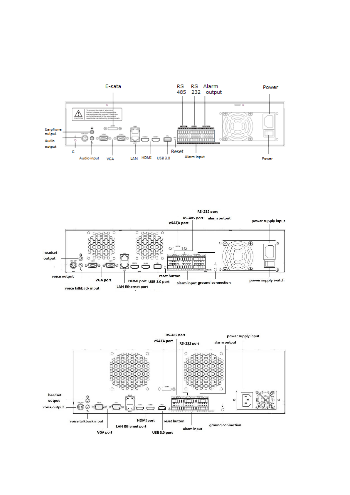
The back panel interface of NR50 standard series NVR (20-channel, 40-channel and
80-channel 8 HDD) is shown below:
The back panel interface of NR50 enhanced series NVR (20-channel, 40-channel and
80-channel 8 HDD) is shown below:
The back panel interface of NR50 enhanced series NVR (80-channel and 160-channel 16
HDD) is shown below:
24
The back panel interface of NR50 standard series NVR (20-channel, 10-channel and
Name
Action
Description
Left button
Click
Preview: select the screen and
display the quickly adding IP
channel interface (IP device channel
is not added).
Preview: display the preview
quitmenu (IP device channel has
been added).
Menu: select and confirm.
Double-click
Switch the single-screen, full screen
and multi-screen display under the
preview and playback status.
5-channel 1 HDD) is shown below:
Description:
The diagram only shows the functions of front and back panel interfaces, and the
specific chassis size shall be subject to the final product.
2.3、Mouse Operation Description
After the USB interface of device is connected with the mouse, the device can be
operated by the mouse. For the specific realizable operations, please refer to the table shown
below:
25

Press and
drag
Turn directions under the PTZ
control status.
Set the area coverage in the mask,
motion detection and video mask
alarm area setting.
Drag the scroll bar of channel and
time display.
Exchange positions of two preview
screens.
Right button
Click
Preview: the right-click menu pops
up.
Menu: log out the current menu and
return to previous level.
Wheel
Scroll up
Upper and lower selection box, scroll
up option.
Scroll bar, scroll up page.
Magnification increases during
electronic amplification .
Scroll down
Upper and lower selection box, scroll
down option.
Scroll bar, scroll down page.
Magnification decreases during
electronic amplification.
Double-click
Main and auxiliary screens are
switched by the mouse.
26

3、Installation and Connection
3.1、Installation Precautions
Warning:
Improper replacement of battery may cause an explosion danger, so it is not
recommended to replace the battery directly by users. If replacement is needed, replace with
the same type or equivalent type of battery only.
NVR is a kind of special monitoring device. Please pay attention to the following matters
during installation:
Do not place the container with liquid (such as water cup) on NVR.
Install NVR at the position with good ventilation. When a number of devices are
installed, the space between devices shall be more than 2cm.
Make NVR work in the allowable temperature (-10℃~+55℃) and humidity
(10%~90%) range.
Make sure to unplug the power line and cut off the power entirely when cleaning the
device.
The dust on the circuit board in NVR will cause shortcircuit after being exposed to
moisture, so please regularly use the soft brush to dust the circuit board, connector
assembly, chassis and chassis fan. If the dirt is difficult to remove, use a diluted
neutral detergent to wipe off the dirt and then wipe it dry.
Do not use the volatile solvents, such as alcohol, benzene or diluent when cleaning
the device; do not use the strong detergent or detergent with abrasiveness which may
damage the surface coating.
27

Please buy the monitoring hard disk from the formal channels to ensure the quality
and operating requirement of hard disk; our company recommends the Seagate
monitoring hard disk.
Make sure that no danger will be caused by uneven mechanical loads.
Make sure that there is enough installation space for video and audio cables and the
bending radius of cable shall not be less than 5 times of external diameter of cable.
Please make sure that NVR is grounded reliably.
Description:
When you receive this product, please make an inventory according to the “Packing
List of Device” in the packing box. If you find that the articles are damaged or
accessories are missed in the packing box, please contact the dealer timely.
3.2、Hard Disk Installation
Our NVR device does not include the hard disk when leaving the factory and the hard
disk needs to be configured and installed according to the recording plan. The disassembly of
chassis and installation of hard disk must be performed by the professional personnel.
Precautions:
Please use the special monitoring hard disk for NVR recommended by the hard disk
manufacturer.
For the maximum number of installed hard disks of device, please refer to the
description in the hard disk file part.
Make sure that the power of device has been cut off before installation.
28

3.2.1、Hard Disk Capacity Calculation Method
Bitrate
File size/hour
Bitrate
File size/hour
96Kbps
42M
128 Kbps
56 M
160 Kbps
70 M
192 Kbps
84 M
224 Kbps
98 M
256 Kbps
112 M
320 Kbps
140 M
384 Kbps
168 M
448 Kbps
196 M
512 Kbps
225 M
640 Kbps
281 M
768 Kbps
337 M
896 Kbps
393 M
1024 Kbps
450 M
1280 Kbps
562 M
1536 Kbps
675 M
1792 Kbps
787 M
2048 Kbps
900 M
3072 Kbps
1350 M
4096 Kbps
1800 M
8192 Kbps
3600 M
16384 Kbps
7200M
According to the recording requirements (recording type, retention time of recording
data), calculate the total capacity needed by a hard disk video recorder and see the specific
details in the appendix of this Manual.
Examples:
Precautions:
The data provided in the table above are for reference only. There may be deviations
between the estimated value of “file size” in the table and actual values, and any loss caused
by the deviations shall be undertaken by users themselves.
3.2.2、Installation Steps of Hard Disk
Installation tools
A cross screwdriver.
Installation diagrams (I):
29

1、 Unscrew the screws at the back and side of chassis and remove the upper cover.
2、 Connect one end of hard disk data line to the SATA interface of NVR mainboard and
connect the other end to the hard disk.
3、 Connect one end of hard disk power line to the SATA interface of NVR mainboard and
connect the other end to the hard disk.
4、 Fix the hard disk screw at the bottom of NVR chassis, put the upper cover on the chassis
and fix it with screws.
30

Installation diagrams (II):
1、 Unscrew the screws at the back of chassis, remove the upper cover and fix the hard disk
on the hard disk support of chassis.
2、 Connect one end of hard disk data line to the SATA interface of NVR mainboard and
connect the other end to the hard disk.
3、 Connect the power line to the hard disk, put the upper cover on the chassis and fix it with
screws.
31
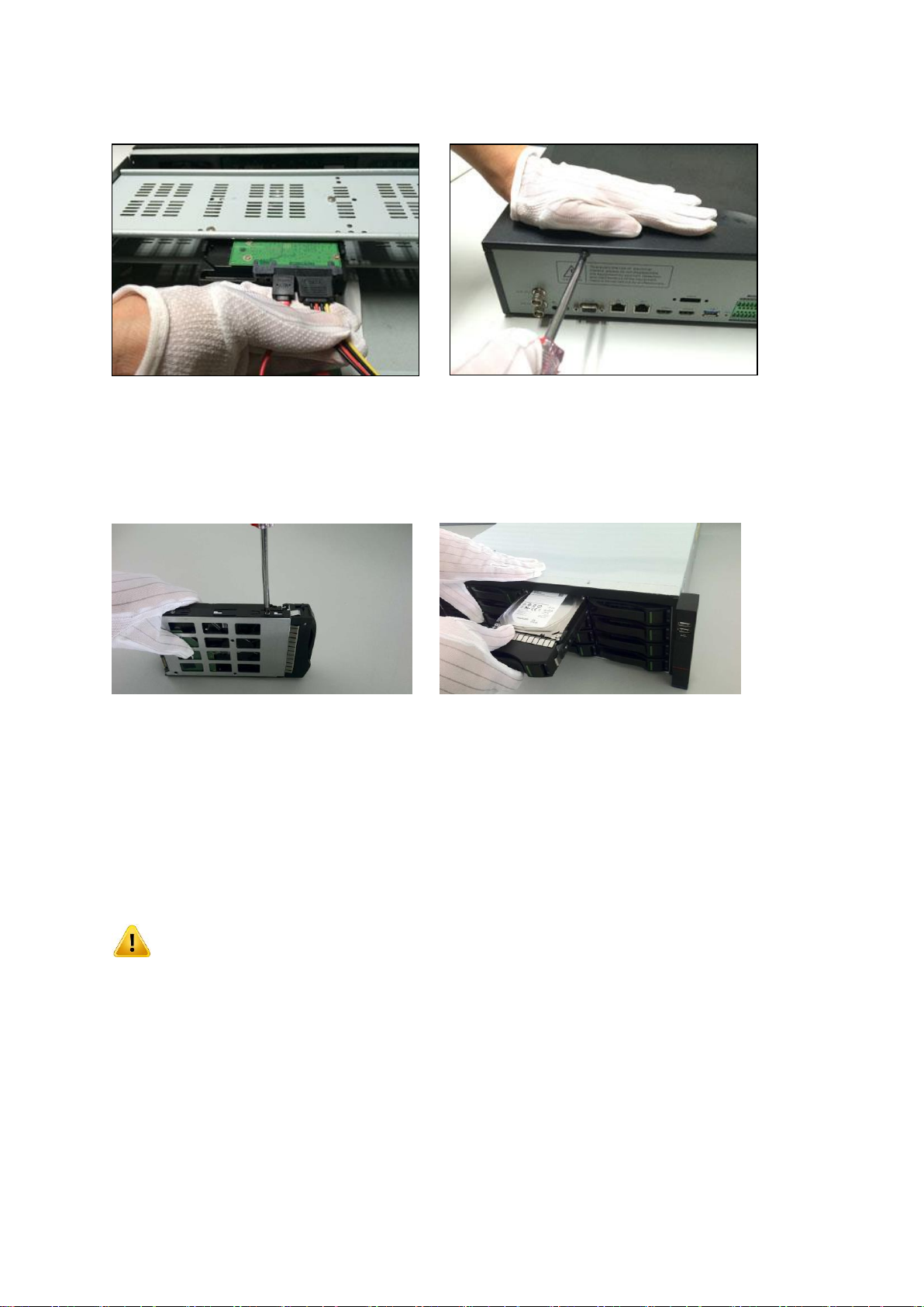
Installation diagrams (III): (Installation diagrams of front hard disk)
1、Install the set screws of hard disk and insert them into the slot positions of corresponding
hard disk on the front panel.
4、Local Configuration and Operation
4.1、Startup and Shutdown
4.1.1、Startup
Precautions:
Confirm that the power required by NVR is used before startup and ensure that the
grouding terminal of NVR is good.
Confirm that the connection between NVR video output and display is good before
startup.
32

When the power supply is abnormal, NVR cannot work normally and even NVR
may be damaged, so the regulated power is recommended for power supply.
1. After the power is plugged in and the power switch on the back panel is turned on, the
device will make a “tick” sound and then start normally.
2. NVR will display the following screen in the startup process:
4.1.2、Shutdown
1、Select “Main Menu->Shutdown” to enter the logout interface, as shown in the figure
below.
2、Users can click “Logout”, “Reboot”, “Shutdown” and other icons for operation.
Precautions:
33

When the system displays “It is shutting down…”, do not turn off the power.
Do not cut off the power forcibly when the device is running.
4.2、Startup Guide
After the device is started, the simple configuration can be conducted for the device
through the startup guide to ensure the normal operation of device.
1、Enter the guide setting interface firstly to set the current language and resolution of output
device. Click “Next” to enter the next interface.
2、Enter the config guide interface and select whether to run the startup guide. If “Yes” is
clicked, enter the next interface; if “No” is clicked, the startup guide will be skipped; if
“Never” is clicked, the startup guide will be closed and also it will be skipped during next
startup.
34

3、After entering the permission identification interface, users shall log in for identification as
the administrator “admin” user. Click “Confirm”to conduct ID confirmation and then enter
the startup guide after identification is successful; if the identification is wrong for 5 times
successively, the device will be locked for 5 minutes; click “Cancel” to skip the startup guide.
Description:
35

Default administrator: admin, default password: admin or 1111.
4、Enter the time & time zone setting interface and click “Apply” to set the time zone, time
format and time; click “Next” to enter the next interface; click “Exit” to log out the startup
guide.
5、Enter the network setting interface and click “Apply” to set the network parameters; click
“Back” to return to the previous interface; click “Next” to enter the next interface; click
“Exit” to log out the startup guide.
36

6、Enter the format disk interface and click “Initialization” to conduct the formatting
operation for the selected disk; click “Back” to return to the previous interface; click “Next”
to enter the next interface; click “Exit” to log out the startup guide.
Description:
The disk can conduct recording normally after the initialization operation is
conducted.
7、Enter the array management interface to conduct array configuration. If the array mode is
enabled, the device needs to be redooted. Click “Back” to return to the previous interface;
click “Next” to enter the next interface; click “Exit” to log out the startup guide. There is no
this page in the startup guide of device which does not support the array management.
37

8、Enter the server search interface to conduct configuration for the digital channel. Click
“Search” to search the digital channel. Click “Back” to return to the previous interface;
click “Next” to enter the next interface; click “Exit” to log out the startup guide.
38
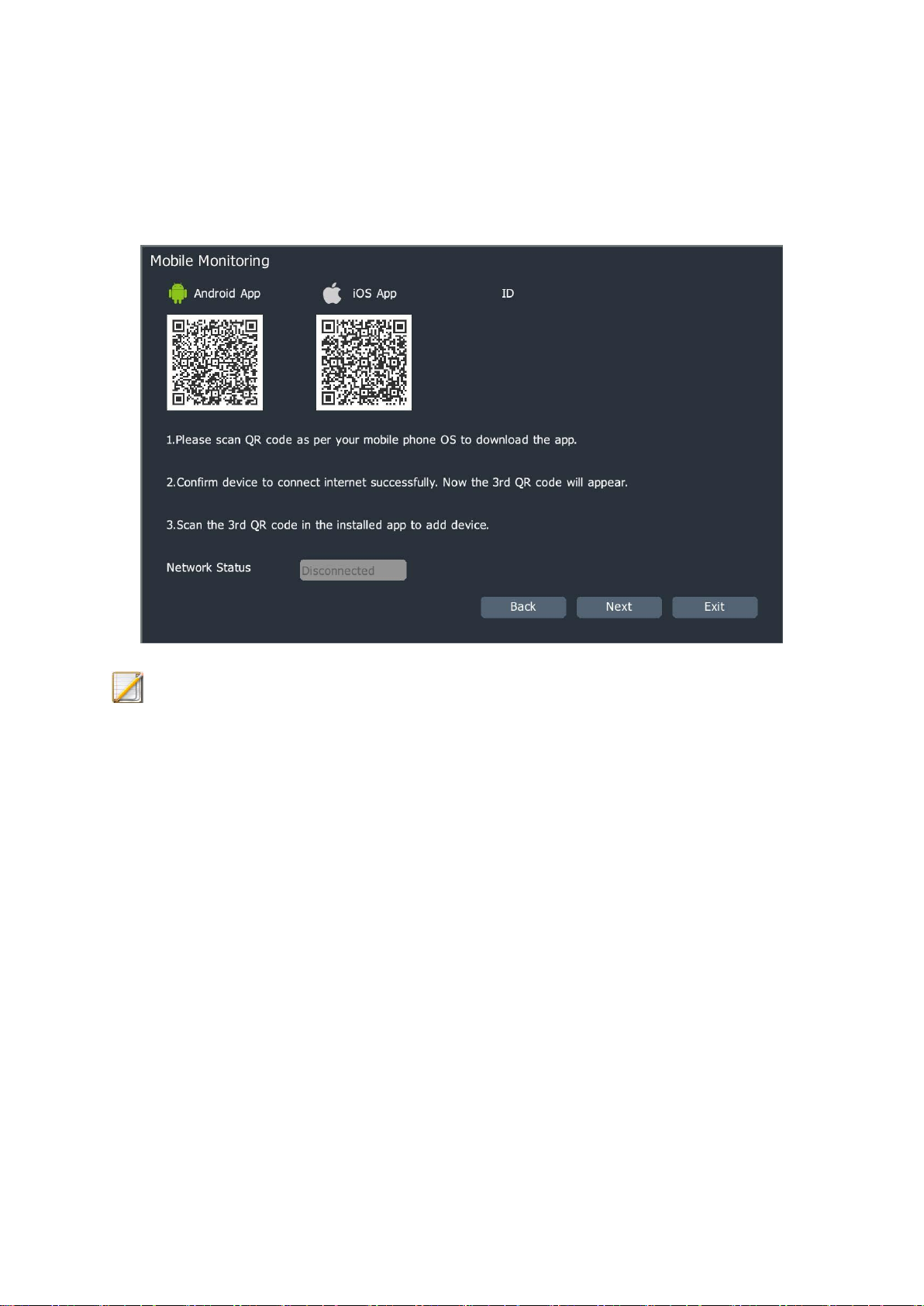
9、Enter the mobile monitoring interface to configure the mobile control device. Click “Back”
to return to the previous interface; click “Next” to enter the next interface; click “Exit” to log
out the startup guide.
Description:
The mobile monitoring mode of some device models is QQ, so please in kind
prevail.
10、After the configuration is completed, enter the guide finished interface; users can select
whether to run the startup guide on the next startup. Click “Back” to return to the previous
interface; click “Finish” to log out the startup guide.
39

11、If the disks which have not been formatted still exist in the system, the prompt shown in
the figure below will pop up. Click “Do” to conduct formatting operation for the disks which
have not been formatted in the system one by one automatically; click “Back” to enter the
preview screen directly.
40

4.3、Channel Management
4.3.1、Shortcut Bar Channel Adding
Users can add an IP channel to the device by the one-key shortcut, and the preview status
will be as shown in the figure below if no channel is added to the channel.
1、After entering the preview interface and clicking the channel display “+” mark, the server
search window will pop up, as shown in the figure below.
41
Description:
Add channels by default port, user name and password; if the information of channel
does not meet the default information, users can edit the “Manual Add” to add
channels.
2、After the search is completed, the adding can be completed by double clicking on the
search list or selecting the channel and click “Add”.
3、Users can also configure parameters by themselves to add number channels. After the
“Manual Add” is clicked, the “Digital Channel” window will pop up, as shown in the figure
below.
4、The adding can be completed successfully after the front-terminal IP address, port No.,
user name, password and other information are input.
Description:
If the channel is the local channel of PSE-NVR is and there is no connection, modify
the PSE channel adding mode to manual adding automatically after quick adding.
The plug-and-play function is enabled by default on the POE power supply network
42

port of PSE series NVR; do not connect the network port to LAN; otherwise, the IPs
of other devices in LAN will be automatically modified.
4.3.2、General Digital Channel Adding
1、Select “Main Menu->Channel Management->Channel Configuration->Basic
Configuration” to enter the channel configuration interface, as shown in the figure below.
Description:
The page tag pages of devices of different models are different.
After the adding is completed, users can view the adding result in the list of added
devices.
When the exclamation mark is displayed for the connection status, the cause for
connection failure can be displayed when the mouse is moved to the icon.
2、After clicking “Search”, the device will start searching. The search results will be sorted
automatically according to the IP addresses. The IP front terminal in the list of search results
can be modified. After is clicked, the modifying IP interface will pop up, as shown in
the figure below.
43

Click “Advanced” to conduct searching according to different connection modes, as
shown in the figure below.
3、Select the IP channel to be added in the search list, click “Add” or double click the mouse
to add the IP device to the idle channel of NVR, and support to select multiple IP channels
for adding.
44
Description:
When the adding mode of digital channel of PSE-NVR is plug-and-play mode, the
channel has been occupied.
Manual adding
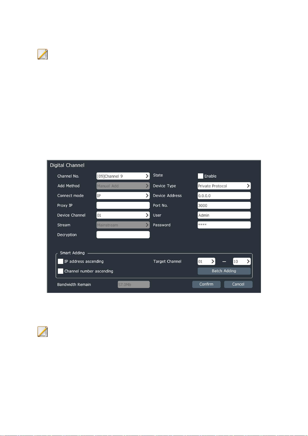
1、In the Channel Configuration->Basic Configuration interface, click “Manual Add” to enter
the digital channel interface; when the device type is private protocol, it is shown in the
figure below.
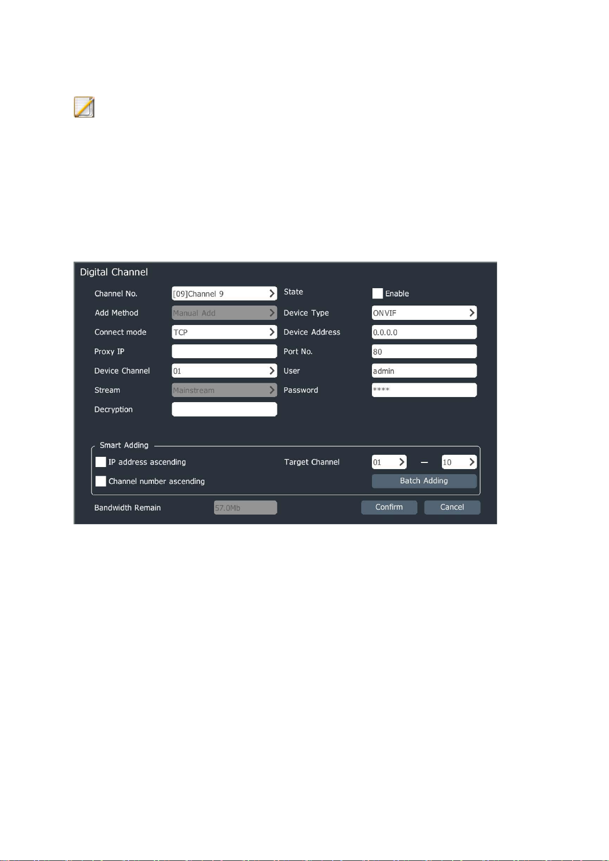
2、Select the channel No. to be added, check “Enable” and select the connect mode according
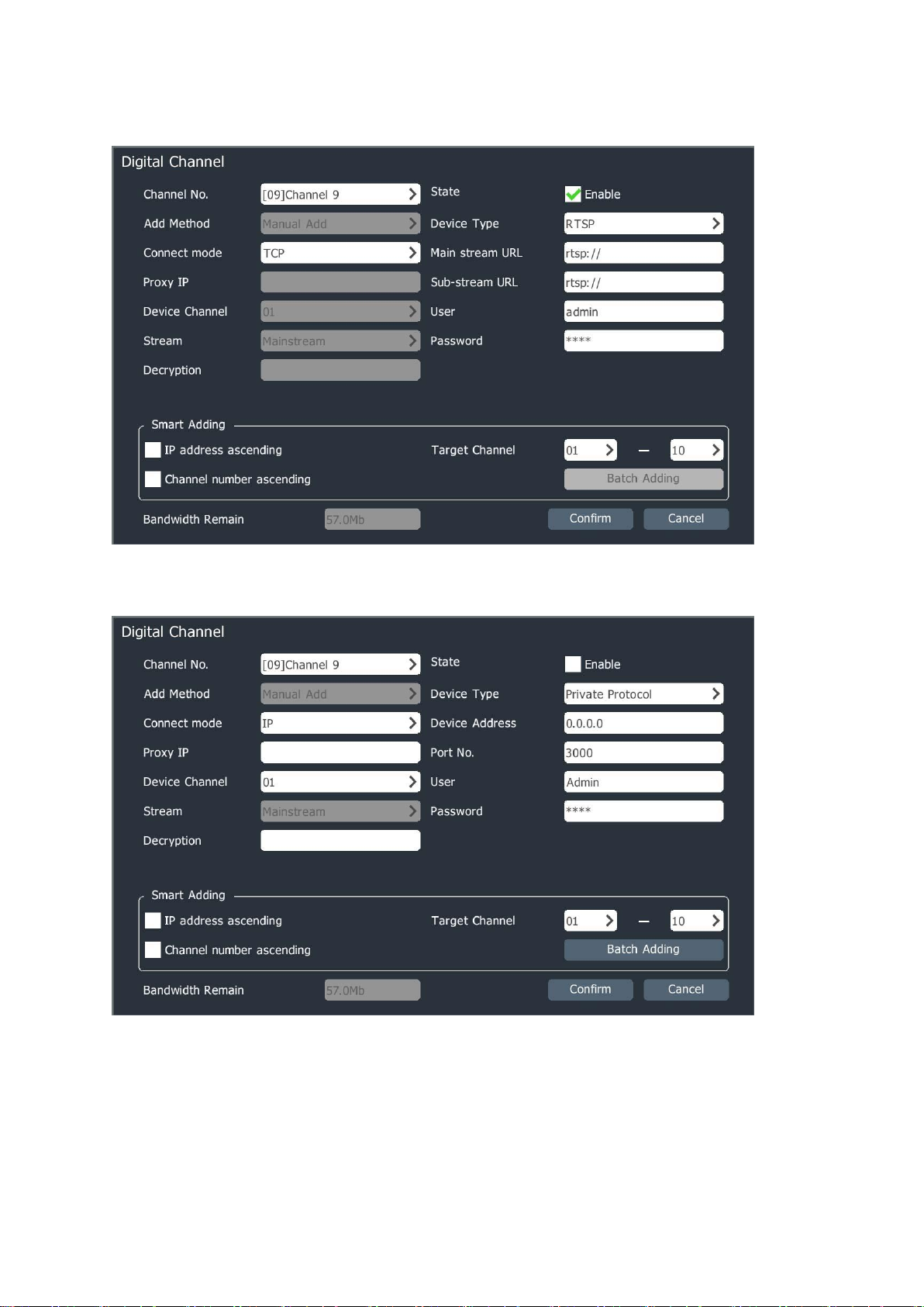
to the device type; when the device type is RTSP, it is shown in the figure below.
45
When the device type is ONVIF, it is shown in the figure below.
3、Input the IP address or URL address of front-terminal device, input the user name,
password and other information, and then click “Confirm” to finish the digital channel adding.
Repeat this operation to finish the adding of other digital channels.
46

Description:
If the device to be added is a multi-channel NVR, users can select the channel No. to
be added in the “Device Channel” and add the corresponding multiple channels of
one NVR at the same time.
Conduct the smart adding, batch adding and adding according to the adding rules
and target channel; skip the current channel if the target channel includes the current
channel. If users select IP address ascending, the last bit of IP will not increase after
it reaches 255.
When the device type is ONVIF, the port No. defaults to 80 and the user name and
password default to admin. The account numbers and passwords of devices from
different manufacturers may be different and need to be modified according to the
actual situations.
4.3.3、 POE Camera Adding
1、In the Channel Configuration->Basic Configuration interface, click in the list of
added devices or double click the PSE channel to enter the digital channel interface.
2、The “Plug-and-play” and “Manual Add” modes are supported as the PSE channel adding
modes:
1) If “Manual Add” is selected, the device shall be connected to the network
interconnected with IP channel and other configuration methods are the same as that of
general digital channel.
2) If “Plug-and-play” is selected, the front terminal to be added shall be connected to the
independent ethernet port of device with POE power supply. The device will finish the
connection automatically.
47

4.3.4、Plug-and-play Setting
To make it convenient for users to quickly add the devices in the same network segment,
users can select the “Plug-and-play” function to conduct the channel adding. Three modes
can be selected for the plug-and-play of channel configuration interface:
1) Not enabled: the plug-and-play function is not enabled and users can manually set the
digital channel and connect the video.
2) Auto adding: under this mode, the device will automatically search channels and add
them to the digital channel.
3) Auto finding: after this mode is set, log out the interface to the preview interface. The
device will search the front-terminal connectable devices and the prompt window of new
device found will pop up in the UI preview interface, as shown in the figure below; users
can decide whether to add the new device found and set the digital channel to be added
by themselves.
Description:
Plug-and-play is generally used for PSE series NVR product, the 3520D basic
version device defaults to enabled status and other NVRs do not enable it generally.
48

The plug-and-play function will clear the list of added devices and automatically
modify the IP address of front-terminal device searched, so it is recommended that
clients shall pay much attention when using the plug-and-play function.
If users select to add and set the digital channel manually, the plug-and-play shall not
enabled.
The channel list of PSE devices cannot be deleted manually.
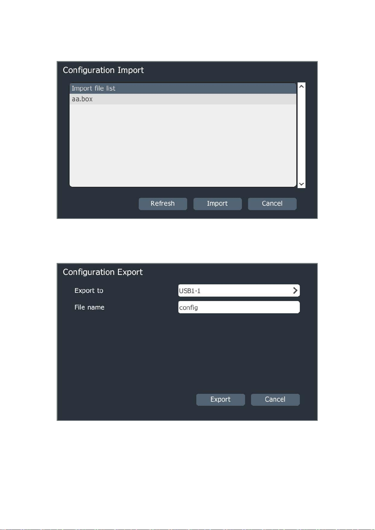
4.3.5、Configuration Management
Users can import and export all channel parameter configurations through the
configuration management.
1、Select “Main Menu -> Channel Management -> Channel Configuration -> Configuration
Management” to enter the configuration management interface; if the mobile storage device
has been connected, click Export to export all the channel configuration parameters, and save
the exported parameters as .xls files; users can manually edit the exported parameters on the
computer and use them as import parameters, as shown in the following figure.
2、The contents of imported and exported .xls files shall meet the following format,
49
Wherein:
(1) In “Enable Identification”, 0: disable, 1: enable;
(2) In “Stream Type”, 0: mainstream, 1: substream 2: picture stream;
(3) In “Transfer Protocol”, 1: TCP, 2: UDP, 3: multicast
(4) In “Connect mode”, 0: IP, 1: domain name, 2: active mode;
(5) In “Preview Mode”, 0: flat tile on the display area, 1: keep the widescreen proportion
display.
3、The format of exported .xls file is word 2003 version and this file can be edited and
imported to the device with office 2003 and higher version.
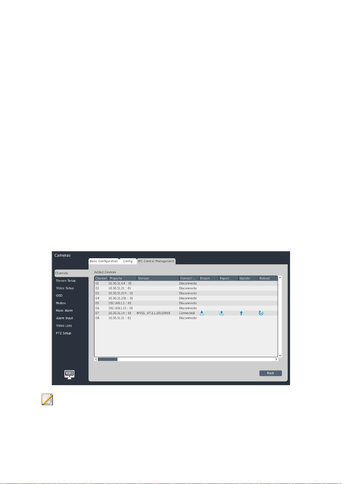
4.3.6、IPC Central Management
Users can conduct the parameter import and export, remote upgrade, IPC reboot and
other operations for the added front-terminal device through the IPC central management
function.
1、Select “Main Menu -> Channel Management -> Channel Configuration -> IPC Central
Management” to enter the IPC central management interface, as shown in the figure below.
Description:
50

The interface can display the channel No., attribute, version number and connection
status of added front-terminal device and also the parameter import and export,
remote upgrade, IPC reboot and other operations can be conducted.
2、Parameter import/export
1) Select the front terminal to be operated in the list of added equipment.
2) After clicking “ ”, the configuration import prompt box will pop up, as shown in the
figure below:
3) Click “Confirm” to enter the configuration import interface, as shown in the figure
below:
51
4) Export the front-terminal configuration parameters and click “Parameter Export” to
make the configuration export interface pop up, as shown in the figure below.
5) Select the storage device, fill in the exported file name and click “Export” to export
the front-terminal configuration; after the export succeeds, the prompt window pops up,
as shown in the figure below.
52

3、Remote upgrade and IPC reboot
1) Select the channel to be upgraded or rebooted in the list of added devices.
2) After clicking “Remote Upgrade”, the IPC upgrade interface will pops up, as shown in
the figure below.
3) Select the configuration file to be upgraded and click “Upgrade” to finish the IPC
upgrade.
53

4) Click “Reboot IPC” and reboot the selected device remotely.
4.3.7、POE Power Information
PSE series NVR has this function and other models do not have this function.
1、Select “Main Menu -> Channel Management -> Channel Configuration -> POE Power
Information” to enter the POE power information display interface, as shown in the figure below.
Description:
“ ” means that the power supply of POE port is normal and “ ” means that no
camera is inserted into this port or the power supply of this port is abnormal.
The real-time power information of this POE port is displayed above the port “ ”.
For POE power precautions, see the interface description.
4.3.8、Encoding Setting
1、Select “Main Menu -> Channel Management -> Encoding Setting” to enter the encoding
setting interface, as shown in the figure below.
54

Audio/video parameter
2、Select the channel to be set and set the audio/video parameter:
Channel No.: select the channel with parameters to be set. The video compression
parameter type includes mainstream (general), mainstream (alarm), customization 1
and customization 2.
Encoding mode: the system supports H.264 and H.265 codes. Three encoding modes
(high profile, main profile and baseline) can be selected.
Resolution: set the resolution of front-terminal device.
Enable corridormode: when the resolution is 16:9 (e.g. 1080P), the corridormode can
be enabled. After the corridormode is enabled, the resolution of video is adjusted to
9:16.
FrameRate: the framerate of video refers to the number of video frames per second
and it can be selected by pull-down list or edited.
BitRate Type: “Variable BitRate” and “Constant BitRate” can be selected. The
variable bitrate accords with the scene changes and the constant bitrate will encode
in accordance with the set bitrate.
BitRate: it can be selected by pull-down list or edited and the value range is
32-16384Kbps.
55

Stream Type: the combined type option provides 2 choices: “Video” and “Audio”.
“Audio” includes video and audio information and “Video” only includes video
information.
Click “More Setting” to expand the setting options of quality, I-frame interval, audio
code, audio type and input volume.
Quality: there are 5 levels of quality: best, better, good, normal, worse. The image
quality is in direct proportion to the bitrate: the better the image quality is, the higher
the bitrate will be.
I-Frame Rate: I frame is the key frame and it means how many video frames contain
a I frame. If I frame rate is 100, there is a I frame in each 100 frames of videos. I
frame rate is inversely proportional to the bitrate: the bigger I frame rate is, the
smaller the bitrate is. It is recommended that the setting value of I frame rate is the
same as that of frame rate.
Audio code: the system provides 4 audio encoding modes:
ADPCM_D(ADPCM_DIV4), G.711A and G.711U. Three audio sampling rates (8K,
32K and 48K) are provided at the same time.
Audio type: it refers to the audio type used by the front terminal and it supports two
types: Lineln and MicIn.
Input volume: it refers to the input volume of corresponding channel and the range is
0-100.
Substream can be set separately. Refer to the setting mode of mainstream.
Description:
When the “Constant BitRate” is selected as the bitrate type, the image quality cannot
be selected.
The substream parameters are used for network transmission. When the network
environment is not very good, users can use the substream for preview to reduce the
transmission bandwidth; the substream is also applicable to the mobile monitoring.
To open the corridormode, the front-terminal IPC support is needed.
56

The encoding parameter templates of front-terminal IPCs of different models are
different.
Click the “More Setting” button to expand and collapse the setting options under the
button.
Key area setting
Set the key area here after the front terminal which supports the key area is connected.
The image displayed in the key area has higher quality.
1、Select the key area attribute page, as shown in the figure below.
2、Check “Area Setting” to enable this function; press the left mouse button on the video and
drag to set the key area. Four key areas can be supported at most. Click “Delete Area” to
delete all set key areas.
3、Click “Apply” to save the setting.
4.3.9、Video Setting
In order to obtain good visual effects, users can adjust the parameters of front-terminal
video according to the scene; after these parameters are adjusted, they will affect the local
preview, recording, network preview and other items.
Select “Main Menu -> Channel Management -> Video Setting” to enter the HD
parameter interface, as shown in the figure below.
57

HD parameter
1、Select the channel to be set.
2、Set the format, video flip, mode and other parameters.
Description:
Brightness, contrast, saturation and hue can be adjusted from 1 to 100.
Shutter speed can be adjusted from 1/100000 to 1 and the bigger the setting value is,
the faster the response speed is.
Gain can be adjusted from 0 to 255.
WDR policy has three options: disable, wide dynamic auto and wide dynamic
manual. The wide dynamic level is displayed when the wide dynamic policy is not
enabled, and the value can be adjusted from 0 to 255.
Digital denoise has three options: disable, normal mode and expert mode; when the
normal mode is selected, the denoise level selection can be seen and the value can be
adjusted from 0 to 255; when the expert mode is selected, the airspace denoise level
and time domain denoise level can be selected and the value can be adjusted from 0
to 255.
Users can select the function of “Copy To Channel” to copy the set parameters.
58

The video input parameters can be adjusted by the mouse wheel and the values can
be increased or decreased by clicking and icons.
3、After the setting is completed, click “Apply” to save the setting parameters.
4、“Reset To Default” means that the default values of all parameters on this page are restored
directly.
Color to grey type
1、Select the channel which needs color to grey setting.
2、The color to grey type includes colored, black and white, inside synchronization, outside
synchronization, day/night and self-adaptive modes.
3、The timing is shown in the figure below.
Description:
The sunrise time and sunset time can be set within the time range of 00: 00~23:59,
and the sunset time must be later than the sunrise time.
4、The outside synchronization is shown in the figure below.
59
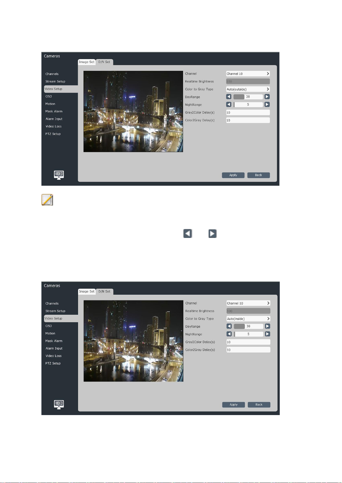
Description:
The brightness value of day and night can be adjusted from 0 to 100 and the values
can be increased or decreased by clicking and icons.
The color to grey delay and grey to color delay can be adjusted from 0 to 120s.
5、The inside synchronization is shown in the figure below.
60
Description:
The day and night brightness values can be adjusted from 0 to 100 and the values
can be increased or decreased by clicking and icons.
The color to grey delay and grey to color delay can be adjusted from 0 to 120s.
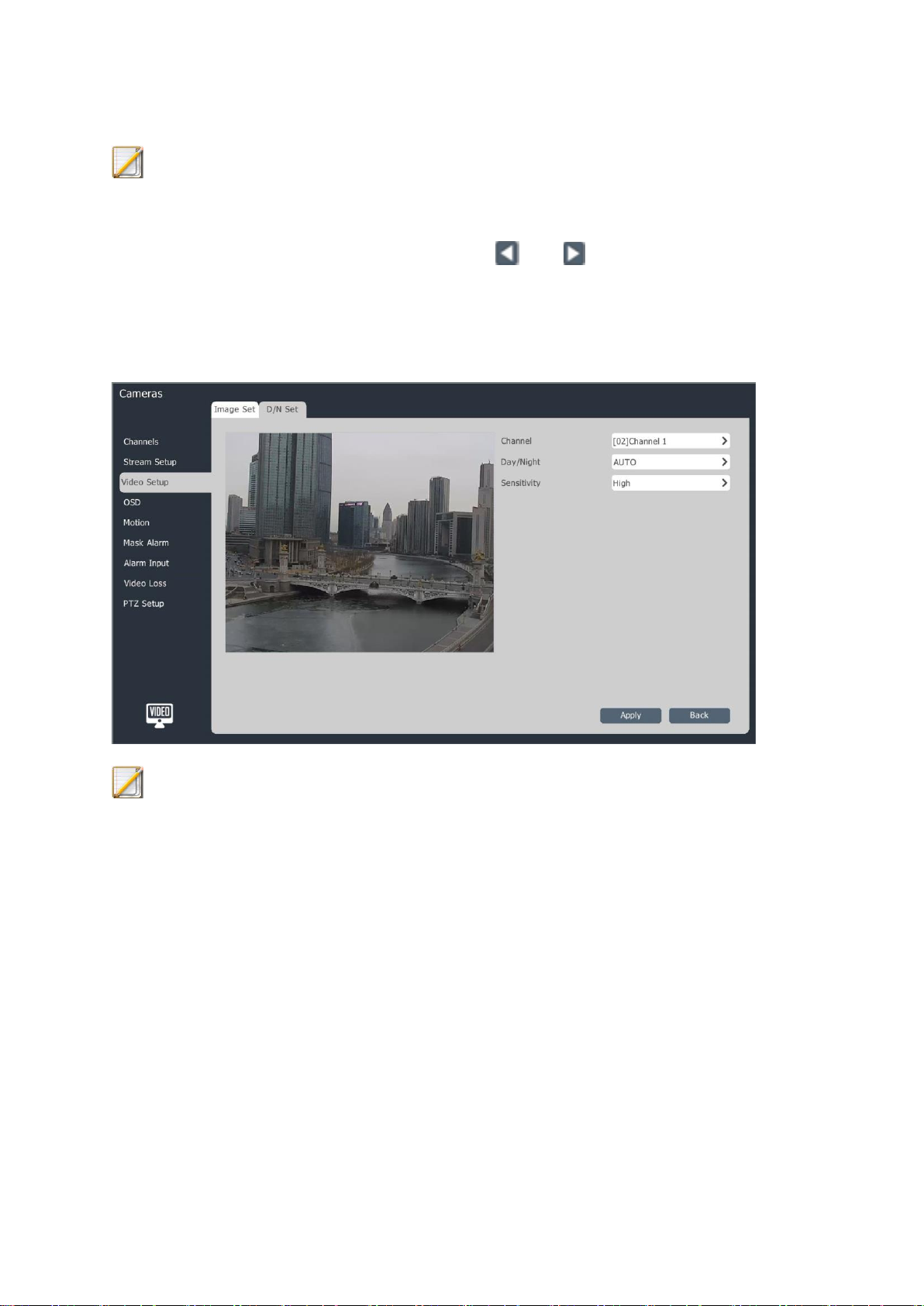
6、The day/night mode is shown in the figure below.
Description:
The day/night mode can be divided into 3 modes: auto, day and night.
The sensitivity can be divided into 3 kinds: high, middle and low.
7、The self-adaptive mode is shown in the figure below
61

Description:
The day/night brightness value can be adjusted from 1 to 100.
The effective delay time of color2 grey/grey2 color is 0-120 seconds.
4.3.10、OSD Superposition Parameter Setting
1、Select “Main Menu” -> Channel Management -> OSD Superposition” to enter the OSD
superposition parameter setting interface, as shown in the figure below.
62

OSD superposition
1、Select the channel which needs OSD setting.
2、Conduct OSD setting for the channel.
If the OSD position of this channel needs to be changed, you can directly drag the mouse on
the OSD box for setting after checking the customized position.
Description:
OSD position includes channel name, date, week, 12-hour system, date format, time
format, OSD color, background color, etc.
Video mask
The video mask function can cover some key areas on the video.
1、Select the channel which needs video mask setting.
2、Drag the mouse to set the video mask area.
Dynamic privacy mask
63

1、Select the channel which needs dynamic privacy mask setting.
2、Control the PTZ through the shortcut PTZ control panel and switch to the screen you want
to cover.
3、Drag the mouse to set the video mask area and click “Add Area”.
4、The added areas are displayed in the list on the right and they can be deleted by clicking
“Delete Area”.
Description:
The front-terminal IPC which supports this function is needed to be added for this
part.
4.3.11、Motion Detection
1、Select “Main Menu -> Channel Management -> Motion Detection” to enter the motion
detection setting interface, as shown in the figure below.
64
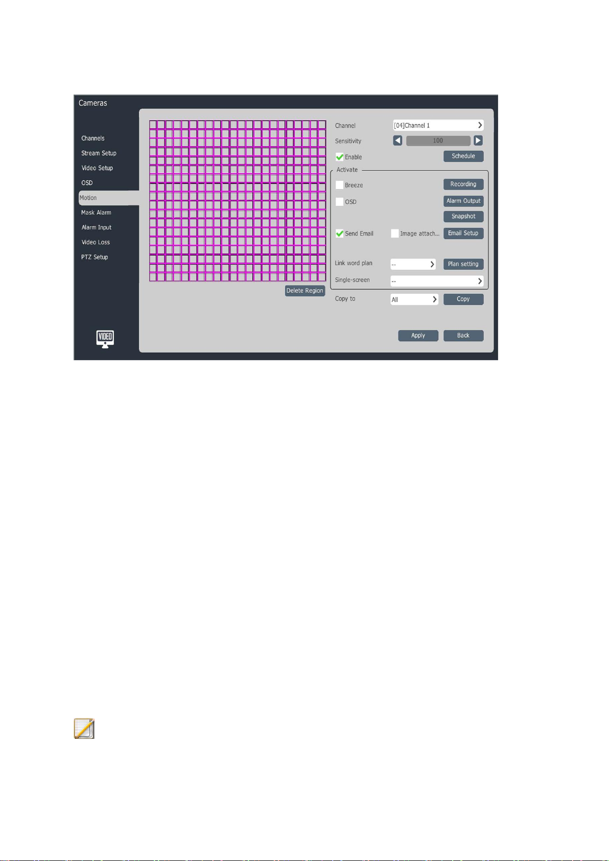
2、Select the channel which needs motion detection setting.
3、Set the arming time of motion detection, detection area and sensitivity; the operations are
as follows:
1) Check “Dispose Motion Detection”.
2) Click “Arming Setting” to set the arming time of motion detection.
3) Draw the area to be detected on the channel video with the mouse.
4) Adjust the sensitivity by using the sensitivity slider. The greater the sensitivity value is,
the more sensitive the motion detection is.
4、Enter “Disposal Mode” to set the motion detection alarm link.
1) The alarm link voive prompt, display, email sending, recording, output, snapshot,
word plan, single-screen and double lamps can be set.
2) After the setting is completed, the parameter copy can be conducted for other channels.
5、Click “Apply” to save the set parameters.
Description:
65

The double lamps can be linked after the front terminal which supports the double
lamp setting is connected.
4.3.12、Mask Alarm
1、Select “Main Menu -> Channel Management -> Mask Alarm” to enter the mask alarm
interface, as shown in the figure below.
2、Select the channel which needs video mask setting.
3、Check “Dispose Video Mask” and enable the mask alarm disposal.
4、Click “Arming Setting” to set the arming time.
5、Selected the “Disposal Mode”, when an alarm occurs, it can activate voice, screen display,
email, recording, output, snapshot, word plan and single-screen.
6、After the setting is completed, the parameter copy can be conducted for other channels.
Click “Apply” to save the set parameters.
4.3.13、Alarm Input Setting
By setting the alarm input, the NVR device can be linked for prompting and recording
when the alarm input alarm situation occurs in the front-terminal IPC.
1、Select “Main Menu -> Channel Management -> Alarm Input” to enter the alarm input
setting interface, as shown in the figure below.
66
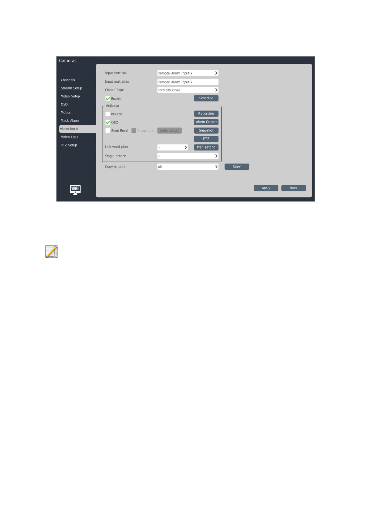
2、Select the input port No. to be set.
3、Select the alarm type.
Description:
Normally open alarm: an alarm is given when the alarm input port of front-terminal
IPC is open.
Normally closed alarm: an alarm is given when the alarm input port of front-terminal
IPC is closed.
4、Check “Dispose Alarm Input” and click “Arming Setting” to set the arming time of alarm
input.
5、Enter “Disposal Mode” to set the alarm link.
1)、The alarm link voive prompt, display, email sending, recording, output, snapshot,
PTZ, word plan and single-screen can be set.
2). After the setting is completed, the parameter copy can be conducted for other
channels.
6、Click “Apply” to save the set parameters.
67

4.3.14、Video Loss Alarm Setting
Set the video loss alarm and link the NVR device for prompting and recording when the
video loss occurs in the channel.
1、Select “Main Menu -> Channel Management -> Video Loss” to enter the video loss setting
interface, as shown in the figure below.
2、Select the channel which needs video loss setting.
3、Check “Dispose Video Loss” and click “Arming Setting” to set the arming time of video
loss.
4、Enter “Disposal Mode” to set the alarm link.
1) The alarm link voive prompt, display, email sending, recording, output, snapshot, PTZ,
word plan and single-screen can be set.
2)After the setting is completed, the parameter copy can be conducted for other channels.
5、Click “Apply” to save the set parameters.
4.3.15、PTZ Control
Set the channel PTZ control protocol, serial port attribute, etc.
1、Select “Main Menu -> Channel Management -> PTZ Setting” to enter the PTZ setting
interface, as shown in the figure below.
68

Icon
Status Description
Alarm (Include motion detection alarm, video mask alarm, port alarm,
video loss alarm, VCA alarm, etc.)
2、Select the channel to be set.
3、Select the PTZ control protocol, address and serial port of this channel. After the setting is
completed, the parameter copy can be conducted for other channels.
4、Click “Apply” to save the set parameters.
Description:
Users can customize the attribute of serial port, set the bit rate, data bit, stop bit and
check bit of serial port and select to copy parameters to other channels after setting.
4.4、Preview
4.4.1、Preview Interface Status
In the preview interface, the recording and alarm status of each channel can be displayed
and distinguished by the icons at the top right of each channel. For the preview status
description, please refer to the table below.
69
Recording (Include timing, manual and all kinds of alarm link recording)
This channel is being recorded and an alarm occurs
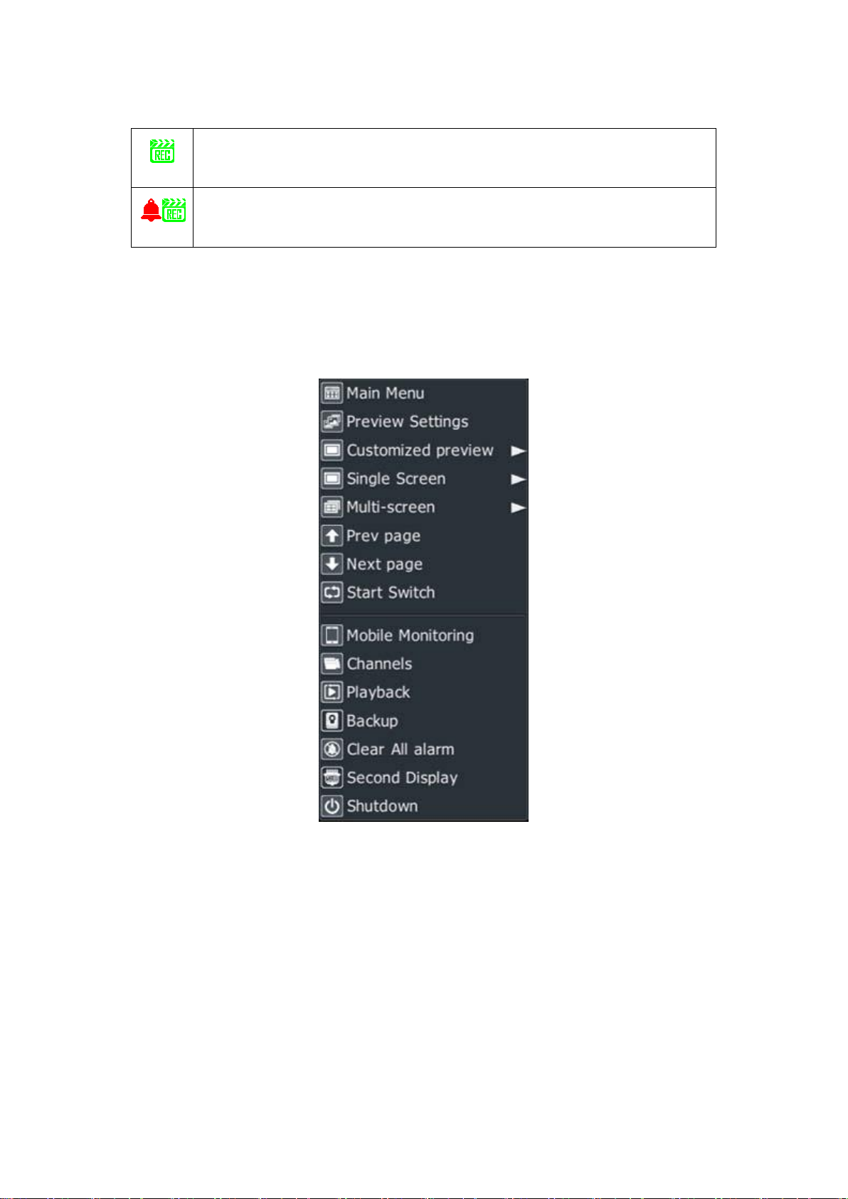
4.4.2、Descriptions for Right-click Menu of Mouse
In the preview status, users can conduct the preview screen switching, preview settings,
channel management, video playback, video opening and other operations through the
right-click menu. As shown in the figure below.
Diagram of right-click menu of mainport
70

Diagram of right-click menu of auxiliaryport
Name
Description
Main menu
Enter the main menu of system.
Preview settings
Enter the preview settings interface.
Customized preview
Directly apply the specific number of
screens and scene configuration set by
users previously. See the setting mode
in “Preview Settings -> Customized
Preview Interface Description”
Single-screen
Select the channel through the
pull-down menu for single-screen
switching.
Multi-screen
Change the preview mode through the
pull-down menu options.
Prev page
Switch the previous screen.
Next page
Switch the next screen.
Description for right-click menu item of mainport
71

Start switch
Switch the display of next screen
constantly according to the preview
settings conditions, and start with the
first screen after reaching the last
screen.
Mobile monitoring
Download the mobile monitoring client
and QR code of connecting device.
Channels
Enter the channel management
interface.
Playback
Enter the video playback interface.
Backup
Enter the backup interface.
Clear all alarm
Clear all current alarms of system.
Auxiliaryport
Switch the mouse operation from
mainport to auxiliaryport.
Shutdown
Logout, reboot or shutdown.
Description:
If the “Customized Preview” operation is needed, please set the configuration of
“Customized Preview” in the preview settings in advance.
If “Start Switch” operation is needed, please set the “Cruise Interval” in the preview
settings in advance.
Through the mobile monitoring, not only the client download of Android and Apple
IOS version can be provided, but also the public network connection status can be
seen.
NR1016-S8, NR1032-S8, NR20xx-S8, NR20xx-E8 and NR20xx-E16 models have
main and auxiliaryport setting and other models do not have auxiliaryports.
Description for right-click menu item of auxiliaryport
72

Name
Description
Preview
settings
Enter the preview settings interface.
Single-scree
n
Select the channel through the pull-down menu for single-screen
switching.
Multi-screen
Change the preview mode through the pull-down menu options.
Prev page
Switch the previous screen.
Next page
Switch the next screen.
Start Switch
Switch the display of next screen constantly according to the preview
settings conditions, and start with the first screen after reaching the last
screen.
Mainport
Switch the mouse operation from auxiliaryport to mainport.
Set as
mainport
Set the auxiliaryport as mainport, which means that the main and
auxiliaryports are exchanged.
Customized preview
Users arrange some specific channels on the same screen display in accordance with the
number of specific screens in advance according to the needs. After selecting a configuration
in the pop-up menu of “Customized Preview”, the preview will become this display interface.
Single-screen
Switch the current screen to a certain specific channel. Select a channel in the pop-up
menu of “Single-screen”, which means that the channel is selected for preview.
Multi-screen
Modify the display mode of output device; the system supports
1/3/4/6/8/9/10/13/16/20A/20B/25/32/36/40/64 screen preview; select the multi-screen
preview, which means that the preview is conducted according to the number of screens.
73

Description:
Icon
Menu
Video Playback
Recording Setting
Preview Settings
PTZ Control
Channel
Management
For NR20-S series and NR20-E series NVRs, except for 20-channel device,
VGA1/HDMI1 supports 64 screens at most and VGA2/HDMI2 supports 32 screens
at most.
Page up and down
Click the “Prev Page” button on the right-click menu to switch to the previous screen and
click the “Next Page” button to switch to the next screen.
Start/stop switch
After the shortcut menu is selected on the mainport/auxiliaryport and then “Start Switch”
is selected, the mainport/auxiliaryport will start the switching operation according to the set
cruise sequence; if “Stop Switch” is selected, the mainport/auxiliaryport will stop switching.
4.4.3、Super Taskbar Menu Description
By sliding the mouse to the right side of display interface, the super taskbar will appear;
a menu of main menu can be entered by one key, the video playback, recording setting,
preview settings, PTZ control are fixed at the first four items, and other icons are updated
dynamically according to the clicking frequency. As shown in the figure below.
74

System Setting
Backup
Alarm Setting
VCA
User Management
Button
Decription
PTZ Control
OSD Superposition
Instant Playback
Manual Snapshot
/
Start/Stop Manual Recording
4.4.4、Easy Operation of Preview
1、Enter the preview status and select the channel to be operated by the left mouse button,
namely the display shortcut bar below red box, as shown in the figure below.
2、The PTZ control, instant playback, manual snapshot, manual recording, electronic
amplification, talkback, channel information editing and other operations can be conducted
by using the quitmenu. For specific operations, refer to the figure below.
75
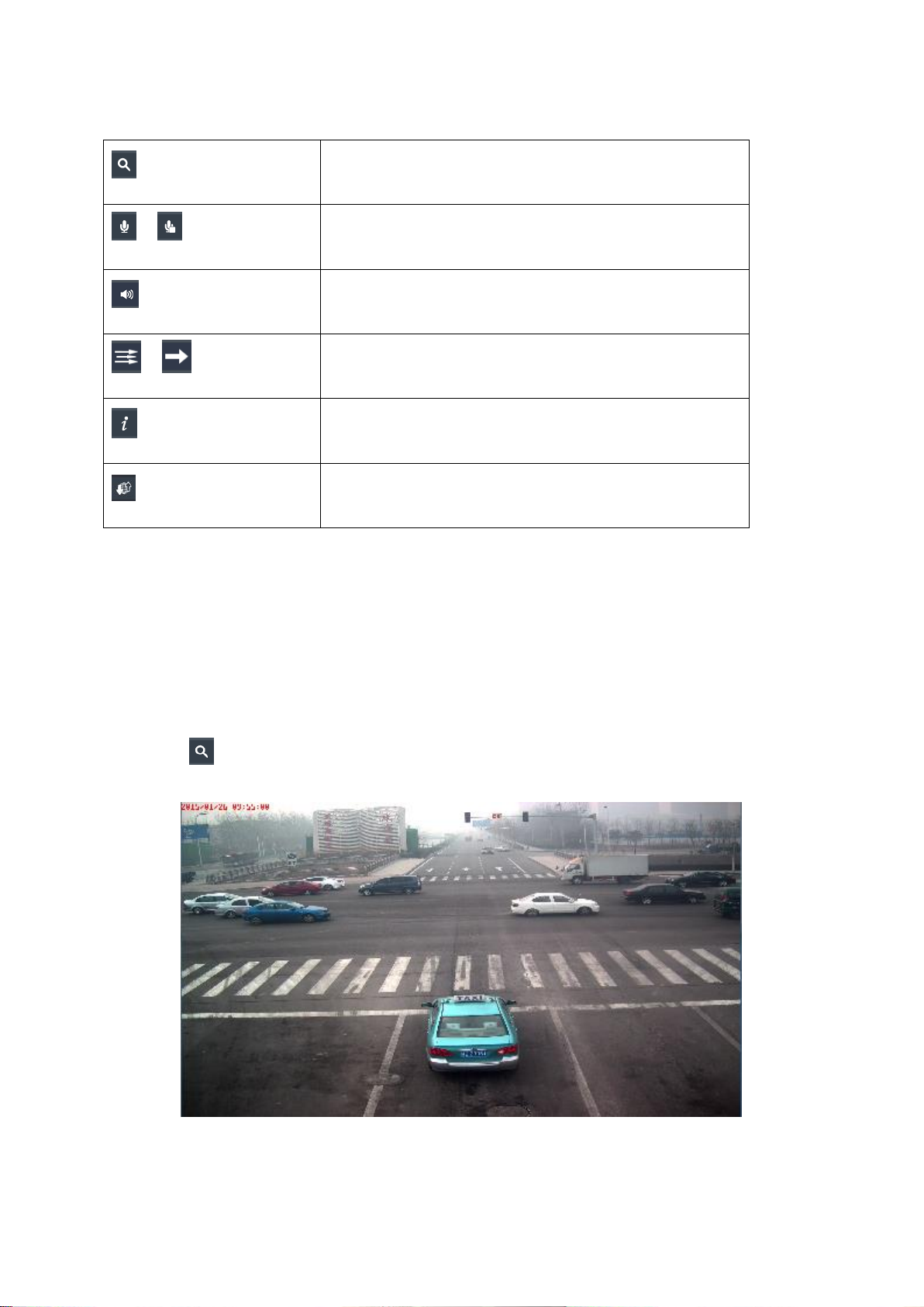
Electronic Amplification
/
Start/End Talkback
Adjust Volume
/
Low Delay/High Fluency
View/Edit Channel Information
View Encoding Parameter
Instant playback
Play back the video of this channel within 5 minutes; a prompt of “Instant playback
fails” will appear if there is no video of this channel.
Electronic amplification
1、Click . Enter the electromic amplification interface, as shown in the figure below.
Original video:
Effect screenshot of electronic amplification:
76

2、Scroll the mouse wheel for amplification or shrinkage; the amplified or shrunk area centers
on the current position of mouse.
3、Users can also click the “+” and “-” at the upper left corner of screen for amplification and
shrinkage. Amplification and shrinkage are all conducted around the center of current screen.
4、When the video is amplified, the left mouse button can still be used to drag the image to
replace the amplified area.
5、Click the right mouse button to log out the electronic amplification.
Description:
According to the different disposal capacities of devices, the maximum amplification
factor is 8 or 16 times.
High fluency/low delay:
If the high fluency is selected, NVR device will ensure the fluency according to the
network situation. If the low delay mode is selected, the video delay will be reduced.
4.4.5、Preview Parameter Setting
1、Enter the preview status, select “Preview Setting” through the right mouse button to enter
the preview setting interface, as shown in the figure below.
77

2、Preview Setting->Basic Configuration Interface Description:
Output device: select a video output device in the pull-down list of “Output Device”,
HDMI2/BNC, VGA/HDMI and VC (when the last channel is set as the virtual
channel, VC is displayed here).
Output resolution: 800*600, 1024*768, 1366*768, 1440*900, 1280*800, 1280*720,
1920*1080, 2560*1440, 2560*1600, 3840*2160, etc. There are differences among
the items in list due to the differences among devices.
Automatic detection: optimum resolution of self-adaptive display.
Cruise interval: set the automatic switch time interval of preview; there are 8 kinds
of optional intervals, including no cruise, 2 seconds, 3 seconds, 5 seconds, 10
seconds, 15 seconds, 30 seconds and 60 seconds.
Preview mode: set the configuration situation of screen quantity, including
single-screen, three screens, four screens, six screens, eight screens, nine screens, ten
screens, thirteen screens, sixteen screens, twenty screens A, twenty screens B,
twenty-five screens, thirty-six screens, forty screens, sixty-four screens, etc. There
are differences among the items in list due to the differences among devices.
Mainport setting: NR1016-S8, NR1032-S8, NR20xx-S8, NR20xx-E8 and
NR20xx-E16 models support this setting and other models do not support that.
78

Output mode: set the display effect of VGA output; four optional modes are
supported: standard, soft, bright and highlight.
Preview effect: the system selects “Auto” by default, which means that the
substream preview will be conducted after startup. Best image quality: to ensure the
preview effect, all channels use the mainstream for preview. Maximum preview
performance: the system adjusts the mainstream and substream according to the
current preview performance.
Alarm screen switch interval: set the single-screen display time interval of alarm link;
there are 5 kinds of optional intervals: 2 seconds, 3 seconds, 5 seconds, 10 seconds
and 15 seconds.
Keep the last frame: configure this item; after the front-terminal camera is offline,
the preview will stay at the last frame. Otherwise, “No Video” will be displayed.
3、Preview Setting -> View Configuration interface description
Select the screen number on the right, double click the screen to delete the preview
channel and double click the left button on the channel No. of table on the left to configure
the channel No. to the specific position. Click the automatic configuration and clear all at the
lower right to open or close all preview channels.
Description:
79
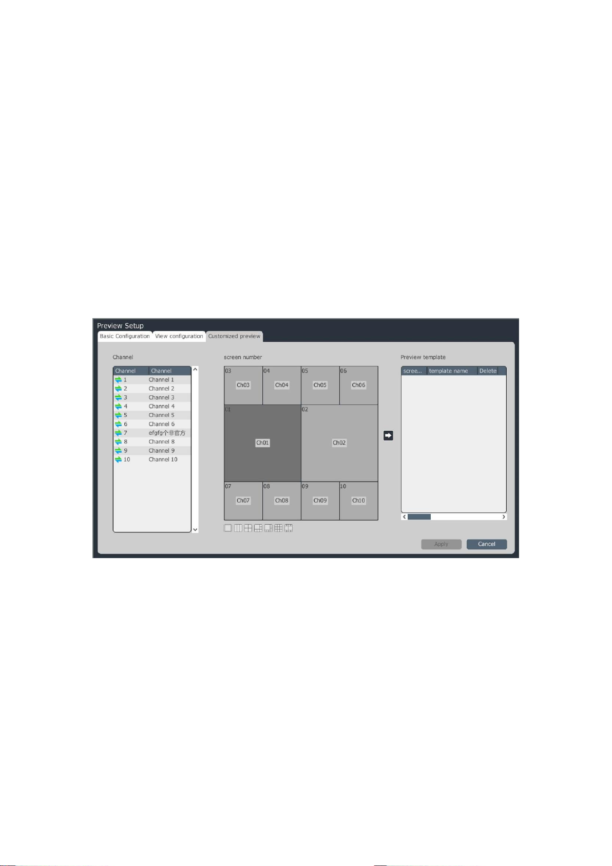
The output devices of standard series NVR (16 channels and 8 HDD and 32 channels
and 8 HDD) model include HDMI2/BNC and VGA/HDMI1.
The output devices of NR20-S series and NR20-E series NVRs (NR20xx-S8,
NR20xx-E8 and NR20xx-E16) models include VGA1/HDMI1 and VGA2/HDMI2.
When the maximum preview performance is switched from mainstream to substream,
there may be no sound for UI preview at this time because the substream is not
composite audio by default. Due to the limit of device performance, other streams
cannot be linked again when the accessed stream reaches the upper limit of device
performance.
4、Preview Settings -> Customized Preview interface description
The application method of left and middle of interface is the same as that of view
configuration interface. When the channel is configured, click the arrow between the middle
and the right to add the configuration to the preview template. The supported maximum
number of templates is 8. After the configuration is completed, click “Apply” at the lower
right corner to take effect. The configuration of number of channels and screens can be
changed after the preview template is selected and the template name can be changed by
double clicking the preview template. The preview application is used in the right-click menu
of preview interface.
4.4.6、Information Prompt on Preview Interface
Restricted decoding performance
80
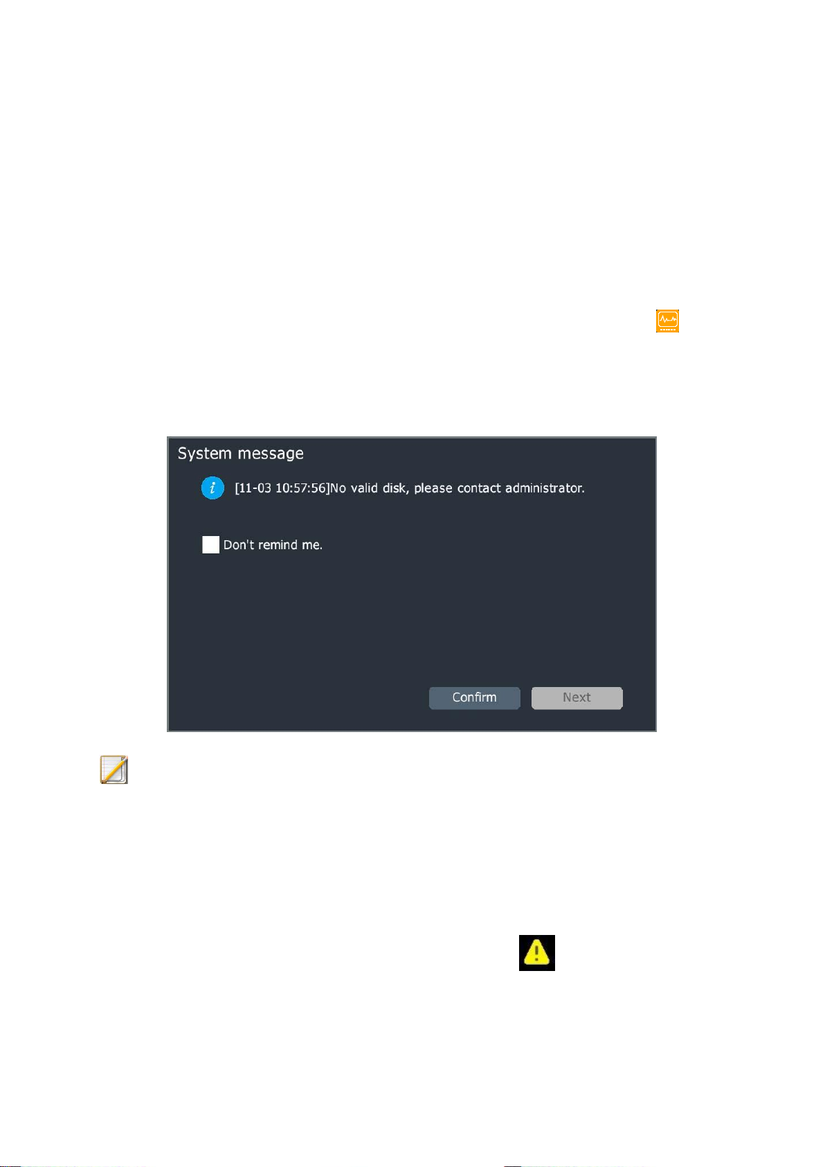
When the decoding performance of device reaches the upper limit, the device will
display the following prompt: “The decoding performance reaches the upper limit, please
disable some channels manually”. Users can configure whether to enable this prompt and the
details are shown in System Setting -> General Setting. It is disabled by default.
Information prompt of system exception:
When the relevant options in System Setting -> Routine Maintenance -> Network
Exception\Storage Exception are enabled and a related exception event occurs, the icon
at the top right corner of screen will flash, system exception will be displayed when the
mouse cursor is placed on this icon, and the system message interface will be opened by
double clicking this icon, as shown in the figure below.
Description:
Users can select “Don’t remind me.” or click “Next” to see the next prompt
information.
Alarm information prompt:
1、When users log off or GUI interface times out, the system will automatically inquire
the alarm logs; when it is found that there is an alarm, the icon at the top right
corner of screen will flash, and the alarm logs during the period from logout or GUI
81
interface timeout to clicking icon can be inquired by clicking the icon, so as to prevent
users from missing alarm information during leave.
2、After the link shout is set for the channel in the VCA, the single-screen of
corresponding channel will pop up and the icon at the top right corner of screen
will flash when an alarm occurs; the shout can be opened by clicking the icon and the
icon changes to at this time. Click the right mouse button to log out the alarm.
4.4.7、Audio Preview and Talkback
Audio preview
After selecting a video channel using the mouse or remote control, the system will
automatically play the audio of this channel.
Voice talkback
Users can use the voice talkback interface of device to realize the talkback function
between remote control terminal and device. Before talkback, please connect the pickup and
speaker well.
4.4.8、One-key Returning to Preview Interface
In the parameter configuration interface, click the icon at the lower left corner to
return to the preview interface directly.
82

4.5、PTZ Control
4.5.1、PTZ Parameter Setting
Description:
Before controlling the ball machine or PTZ of IP channel, users shall confirm the
normal network connection between PTZ decoder and NVR and configure the PTZ
decoder parameters in the device.
The parameter setting of front-terminal IPC serial port is shown in the description of
Section 4.3.15.
The parameter setting of NVR local serial port is shown in the description of system
setting.
4.5.2、PTZ Control Operation
1、In the login status, enter the preview status. Click the channel preview screen which needs
PTZ control operation by the mouse and click the “PTZ” button in the preview shortcut menu
bar to enter the full screen of channel; then the PTZ control window pops up, as shown in the
figure below.
2、Select the channel which will conduct PTZ control.
3、Description of PTZ Action Control:
1) PTZ control: click the button with the mouse to control the upward,
downward, left and right actions of PTZ, click the button with the mouse to
83

control the oblique action of PTZ and click the button to start or stop the horizontal
automatic operation of PTZ.
2) Lens control: the lens iris will be stopped after the button on the left side of “Iris”
is clicked and the iris will be opened after the button on the right is clicked; the lens
focus will become far after the button on the left side of “Focus” is clicked and the lens
focus will become close after the button on the right is clicked; the lens zoom will
become small after the button on the left side of “Zoom” is clicked and the lens zoom
will become large after the button on the right is clicked;
3) Speed setting: click the progress bar to select the value or scroll the mouse wheel to
change the value, and users can also click and icons to increase or decrease the
value; the bigger the value is, the higher the speed of PTZ action is; the default value of
system is L2.
4) Click icon to set the one-key focus function, click icon to enter 3D
positioning function interface and click icon to set opening and closing of front-terminal
laser.
5) Click and icons to expand and collapse the control menu on the right side; the
control menu on the right is shown in the figure below.
84

6) Drag icon to drag the PTZ control window.
7) Click icon to shrink the PTZ control window. In PTZ shrinking status, click
icon to return the PTZ control window. In PTZ shrinking status, press the left mouse
button to control the PTZ direction of ball machine according to the moving direction of
mouse.
4.5.3、Preset, Cruise and Track Setting and Call
Preset setting and call
1、Calling preset: select the preset number in the pull-down list of “Preset” or directly input
the preset number and then click the “Call” button to call the selected preset.
2、Setting preset: after controlling the PTZ action to a specific position, select the preset
number in the pull-down list of “Preset” or directly input the preset number; click the “Set”
button to complete the preset setting operation of this number.
Track recording and demonstration
After clicking the “Start Track” button, the button prompt information is turned into “End
Track” and the system enters the track recording status. At this time, the system will
automatically record all operations conducted for PTZ by users before clicking the “End
Track” button. After the “End Track” button is pressed, the track recording is completed and
the system automatically logs out the track recording status. Users can click the “Demonstrate
Track” button to demonstrate the track recorded just now.
Cruise path setting
1、Click the “Cruise Path” button to enter the cruise path setting interface, as shown in the
figure below.
85

2、The cruise path setting description is shown as follows:
1) Cruise path information browsing
Select the cruise path No. in the pull-down list of “Path No.”; after selecting a cruise
point, the system will automatically display the corresponding preset of the cruise
point and the dwell time of the preset.
2) Editing cruise path
Select the path No. to be edited in the pull-down list of “Path No.”; if the path is
disabled at this time, press the “Enable” button to enable the cruise path. Select the
preset No. in the pull-down list of “Preset”, press the “Add” button after the time is
input; and then the preset is added to the cruise point list of cruising path. After
selecting a cruise point in the “Cruise Point” list, click the “Delete” button to delete
the cruise point from the cruise point list of cruise path. After selecting a cruise point,
select a preset from the pull-down list of preset, enter the time and then click the “Set”
button to modify the configuration information of selected cruise point.
3) Enabling/Disabling cruise path
Select the cruise path No. in the “Path No.” list; users can select to enable or disable
this path.
4) Calling/Stopping cruise path:
Click the “Call” button to conduct cruise according to the set path; click “Stop” to stop
the cruise of current path.
86

5) Logging out cruise path setting interface
If the “Confirm” button is clicked, all path editing operations conducted after entering
the cruise path setting interface will be all saved in the system, and the system will log
out the path setting interface simultaneously; if the “Cancel” button is pressed, the
system will automatically ignore all editing operations and log out the path setting
interface simultaneously.
6) 3D positioning
Users can use the mouse to select any area in the video screen and the system will
automatically control the PTZ lens actions to achieve the zoom function of scene (the
rectangle will be enlarged if it is drawn from left to right and the rectangle will be
shrunk if it is drawn from right to left).
4.5.4、USB Keyboard Control PTZ
1、In the preview mode, use the【↑】【 ↓】button to select the channel which needs PTZ control
operation; after pressing P, the selected channel is diaplayed in the single-screen of system at
this time and “PTZ ChnXX” is displayed at the top right corner of screen to remind users that
the system is in the PTZ control status of XX channel currently.
2、Control PTZ action description
PTZ control: in the PTZ control mode, the upward, downward, leftward and rightward
actions can be controlled by pressing 【↑】【 ↓】【 ←】【 →】 buttons; when the 【Confirm】
button is pressed, the PTZ will start horizontal automatic actions; when the 【Confirm】
button is pressed again, the PTZ will stop horizontal automatic operations.
Lens control: in the PTZ control mode, the lens iris will be opened after I or G is pressed
and the lens iris will be stopped after Ctrl+I or Ctrl+G is pressed; the lens zoom will be
increased after Z or B is pressed and the lens zoom will be decreased after Ctrl+Z or
Ctrl+B button is pressed; the lens focus will become far after F or J is pressed and the
lens focus will become close after Ctrl+F or Ctrl+J button is pressed.
Preset call: in the PTZ control mode, the system will conduct the corresponding preset
call operation after the 【Backspace】 button, 【Number】 button and 【Confirm】 button
are pressed in turn.
Speed setting: in the PTZ control mode, the speed of PTZ action can be set by pressing
the number buttons 【1】~【4】.
87

Logging out PTZ control mode: click the 【ESC】 button in the PTZ control mode to
return to the preview mode.
4.6、Recording
4.6.1、Recording Guide
Enter the main menu and click “Recording Guide” to configure the schedule recording,
motion detection recording, port alarm recording and VCA recording conveniently; the
reference interface is shown in the figure below.
1、Schedule recording setting guide
1) Select “Main Menu” -> “Recording Guide”-> “Schedule Recording” to enter the
“Schedule Recording Setting” interface, as shown in the figure below.
88

2) Click the “Finish” button to save the configuration.
2、Motion detection recording setting guide
1) Select “Main Menu” -> “Recording Guide” -> “Motion Detection” to enter the
“Motion Detection Alarm Setting” interface, as shown in the figure below.
2) Click “Finish” to save the configuration.
3、Port alarm recording setting guide
1) Select “Main Menu -> Recording Guide->Port Alarm” to enter the “Port Alarm
Setting” interface, as shown in the figure below.
89

2) Click “Finish” to save the configuration.
4、VCA recording setting guide
1) Select “Main Menu->Recording Guide->VCA” to enter the “VCA Setting” interface,
as shown in the figure below.
2) Set the configuration parameters related to VCA in the “VCA Setting” interface and
see the specific setting method in the chapters related to VCA. Click “Next” to enter the
“VCA Setting Interface”.
90
3) Set the arming time period of selected channel and disposal mode of un-armed time in
the “VCA Setting” interface. The arming configuration information of this channel can be
copied to other channels. Click “Finish” to save the configuration.
4.6.2、Recording Setting
Basic setting
1、Select “Main Menu->Recording Setting->Recording Template->Baisc Setting” to enter the
basic setting interface of recording template, as shown in the figure below.
2、Select the channel to be set.
91

3、Select whether to conduct “Audio Recording” and enable “Redundant
Recording/Snapshot”, “I-Frame Recording” and “Substream Recording”.
When “Audio Recording” is not checked, only video data is saved in the recording
file.
When there is a redundant disk in the system and the “Redundant
Recording/Snapshot” function is enabled in the selected channel, the recording and
snapshot image files will be saved in the video disk and redundant disk.
When “I-Frame Recording” is enabled, the system will conduct frame extraction
disposal for recording files, and the hard disk space can be saved greatly for the
video of non-key area.
When “Substream Recording” is enabled, the system will conduct the substream
recording and also the substream recording can be viewed in the mobile client.
4、Select the recording type. There are seven optional types in the template: “Timed
Recording”, “Port Alarm”, “Detection Alarm”, “Loss Alarm”, “Video Mask”, “Detection or
Port” and “Detection and Port”. Check “Cancel” to delete the set recording type.
5、By pressing the left mouse button to drag in the time period area, the selected time area
will be updated to the established recording type.
6、Set the prerecording and delay time of alarm recording.
Prerecording time: if it is assumed that the prerecording time set by users is 5S, the
system will automatically save the video information within 5S before the alarm
occurs in the recording file.
Delay time: the recording delay time shall be used in the alarm recording; if it is
assumed that the delay time set by users is 5S, the system will automatically save the
video information within 5S after the alarm is over in the recording file.
If the prerecording time and recording delay time are used cooperatively, it will be
convenient for users to analyze the monitoring information before and after the alarm
occurs.
7、Set the maximum video retention time; the unit is day; if it is 0, it means no limit; the
maximum value of video retention time is 60.
8. Click “Apply” to save configuration.
92

Advanced Setting
1、Select “Main Menu” -> Recording Setting -> Recording Template -> Advanced Setting” to
enter the advanced setting interface of recording template, as shown in the figure below.
2、Select the channel to be set.
3、Set whether to enable the ANR function of front-terminal IPC. If it is enabled, IPC will
automatically start the local recording when IPC is offline, and it will automatically upload
the video saved locally into NVR when IPC is online again.
4、Select the prerecording time in the pull-down list of “PreRecord”.
5、Select the recording delay time in the pull-down list of “Delay”.
6、Set the time period and the recording type within this time period. Click the time period
enabling checkbox to make it be selected. Input the start and end time of time period in the
time period input box. Select a recording type in the pull-down list of “Recording Type”.
Different recording types can be specified for different time periods.
7、Copy the current template parameters to the channel and date.
8、Click “Apply” to save the configuration.
Holidy plan:
93

The holidy recording plan of current year can be configured. After the holiday plan is
enabled, this recording plan is performed preferentially during the holiday.
1、Select “Main Menu->Recording Setting->Recording Template->Holiday Plan” to enter the
“Holiday Plan” interface, as shown in the figure below.
2、Click to select a holiday in the list and click “Edit” or double click the left mouse button to
enter the “Holiday Setting” interface.
94

3、Check “Enable Holiday Plan” and select the holiday setting mode: “Per Date”, “Per
Month” or “Per Week”. Input the start and end date of holiday. Click “Confirm” to save the
configuration.
4、After the holiday plan is enabled, the holiday can be selected in “Date” of “Advanced
Setting” and the corresponding recording template can be set for the holiday. The recording
for all enabled holiday plans shall be conducted in accordance with the template
Description:
Unless otherwise stated, Sunday is considered as the first day of each week for all
configurations per week.
4.6.3、Recording
1、Select “Main Menu->Recording Setting->Recording Strategy” to enter the recording
stategy setting interface, as shown in the figure below.
2、Select the disposal mode of system when there is no enough disk capacity: “Overwrite
File”, “Delete Non-alarm Recording” or “Stop Recording”.
3、Click “Apply” to save the configuration.
4.6.4、Diskgroup Setting
1、Select “Main Menu->Recording Setting->Diskgroup Allocation” to enter the diskgroup
allocation interface, as shown in the figure below.
95

2、Set the disk group or quota.
Disk group: the hard disk attached to NVR can be divided into multiple disk groups and users
can specify the disk group where the recording file is located for each channel.
Quota: specify the maximum disk space which can be occupied by the recording file of
certain channel; different recording occupation spaces can be configured for different
channels.
3、Quota setting.
1) Select “Disk Group” in the “Mode Selection” item.
96
2) Select disk group. There are eight optional disk groups (1~8) in the pull-down box.
3) Select disk for disk group. Set the disks included in the disk group. Check “Select All
Disks” to select all available disk groups. A disk cannot be included in multiple disk groups
simultaneously.
4) Select channels for disk groups. Select the channels which can be recorded in this disk
group.
5) Click the “Apply” button to save the setting.
Description:
The maximum storage bitrate of single disk group is 100Mbps and there may be a risk of
losing video if actual bitrate is higher than this limit.
4、Quota configuration
1) Select “Quota” in the “Mode Selection” item.
2) Select the channel to be set. Select the channel which needs quota setting in the
pull-down box of “Channel”.
3) Set the recording quota. Set the maximum storage space occupied by the recording file
of this channel; the unit is GB and 0 means no limit.
97

4) Set the picture quota. Set the maximum storage space occupied by the picture file of
this channel; the unit is GB and 0 means no limit.
5) Save the setting. Click the “Apply” button to save the setting.
Description:
The quota mode is not recommended for the devices of above 40 channels.
4.6.5、Snapshot Setting
1、Select “Main Menu->Recording Setting->Snapshot Setting” to enter the snapshot setting
interface, as shown in the figure below.
1) Select the target channel No. which needs to conduct the snapshot setting operation.
2) Set the snapshot type which can be divided into two types: “Schedule Snapshot” and
“Alert Snapshot”. When the alert snapshot is selected as the snapshot type, the snapshot
setting interface is shown in the figure below.
98

3) Set the snapshot mode which can be divided into “Single-picture Snapshot” and
“Multi-picture Snapshot”.
4) Set the time interval of snapshot; the unit is second.
5) Select whether to conduct ftp uploading operation for the snapshot picture. Click the
“FTP Setting” button to enter the ftp setting interface; the specific FTP setting methods are
shown in the corresponding chapters.
6) Select whether to conduct SNMP uploading operation for the snapshot picture. Click
the “Email Setting” button to enter the Email setting interface; the specific setting methods
are shown in the corresponding chapters. In this interface, the Email setting is not supported
by alert snapshot.
7) The snapshot setting parameters of current channel can be copied to the specified
channel.
8) Click “Apply” to save the configuration.
Description:
The system can capture 2000 pictures within 24 hours in each channel at most and
the number of captured pictures shall be reset after the system is rebooted.
4.6.6、Rebuilding Index
When an exception of hard disk occus or video is lost, the lost records can be found by
rebuilding the index.
99
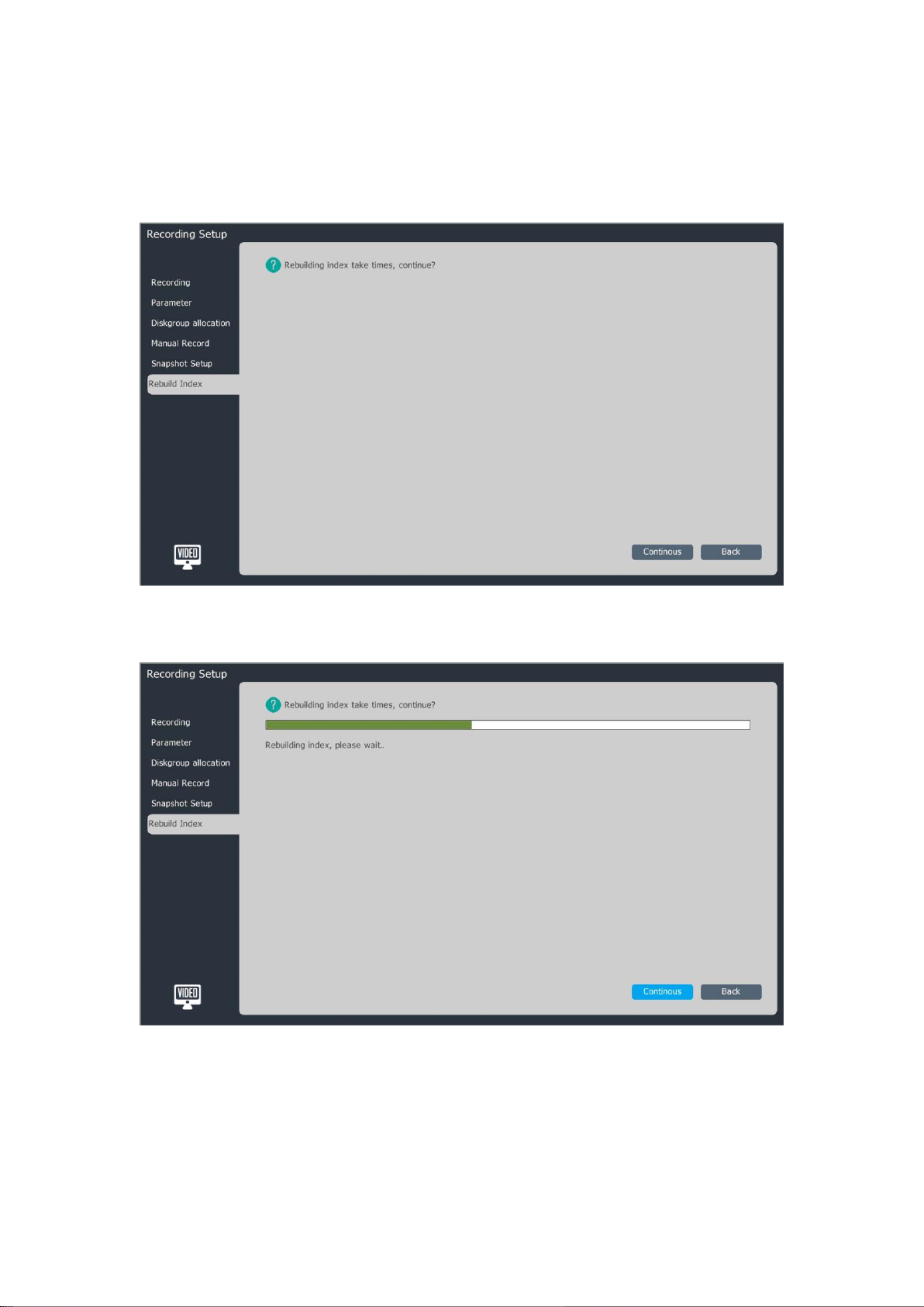
1、Select “Main Menu->Recording Setting->Rebuild Index” to enter the “Rebuild Index”
interface, as shown in the figure below.
2、Click the “Continous” button to start the rebuilding operation.
3、In the index rebuilding process, users can log out the interface for other operations, but
they cannot conduct the video playback.
100
 Loading...