

Thümler Z3, Z50, Z10, Z5, Z20 Operating Instructions Manual
...
1
Operating Instructions
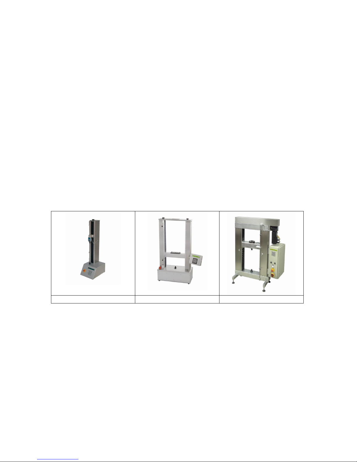
Tensile Testers
Z3, Z5, Z10, Z20, Z50, Z100
Z3 Z5
Z10
Z20 Z50
5-2017

2
Table of Content
1: Introduction
2: Checking Contents and the Number of Machine
3: Power on checks
4: Control Display Unit
5 Menu Keypad
6: Configuration
7: Load Cell
8: Interface USB
9 Upload Hex file
10 Special Programs
11: Accessories, Maintenance
12 Windows-Software
13 Electric plan, Main board
14 Dimensions
15 Declaration of Conformity

3
1) Introduction
Danger Hints
Warning Danger of crushing!
By the accessible design of the machine there is a risk of crushing
Please make sure that during the adjustment and during
the test sequence no one comes to the area of the machine!
The device may only be operated by trained personnel.
Attention! The load cell can be destroyed by overload!
Especially upon moving the grips
or by lateral load is the danger that the load cell will be destroyed.
Install load cells carefully.
There must be no larger torque pull off the grips
pass through the load cell.
For smaller load cells, we recommend using pneumatic grips
4
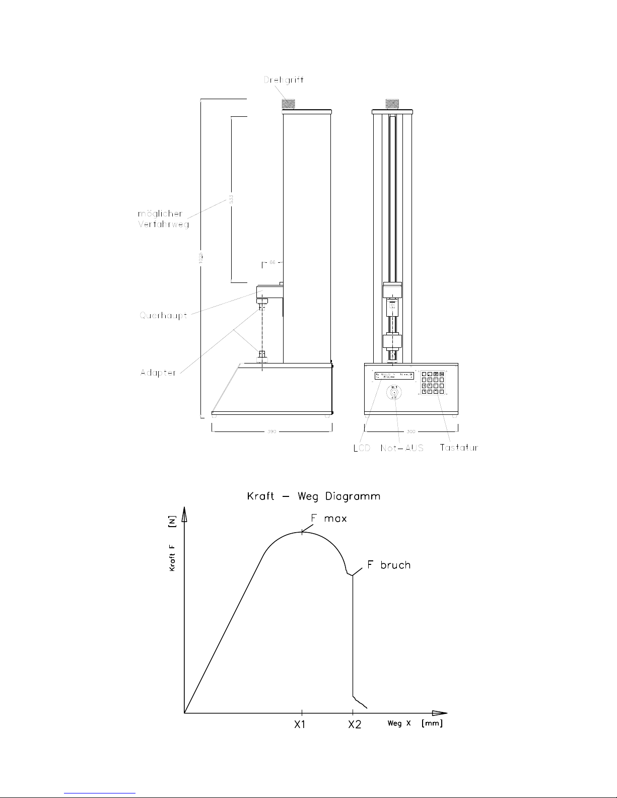
Names

5
Notes
Limit
The limit switch must be set, so that the upper grip do not touch lower
grip.
Transport
Disassemble load cell.
Z3 Z5 and Z10 machines are provided for voltages 230 VAC or 115
VAC See back side of machine
Machine Z20 Z50 Z100 needs 3x 380 Volt
We can decline down to 260 Volt; if it is lower we need a Trafo
1) INTRODUCTION
1.01 This manual is to help the operator understand the operation
principle of the testing machine electronic panel.
These new testing machines represent a range of easy-to-use
compact devices for determining Tension, Compression, Shear,
Flexure and other mechanical and physical properties of materials.
Due to variations in international standards of force and extension
units, the tensile test machines enable the operator to select one of
the two standards for Force Units (Newton and Pounds) and either
Inches or Millimeters for the Extension Units.
1.02 All the controls are located on the front panel, which has a large,
easy-to-read backlit 2-line LCD display and a numeric keypad. The
display unit shows the force and displacement values. Crosshead
control keys are provided for moving crosshead up or down, for
starting a test, or for getting access to various test parameters, such
as, for example, displacement or speed of crosshead. The numeric
keypad permits the inputting of test data.
1.03 There may be many aspects of material testing not covered in
this operation manual in particular the type of grips used and
additional optional equipment (for more information see our webpage
http://www.grip.de/ )
Operating Environment – All machines are designed to operate in
temperatures of 0 to 38°C (32 to 100°F) with a non-condensing atmosphere of
10 to 90% Relative Humidity.
6
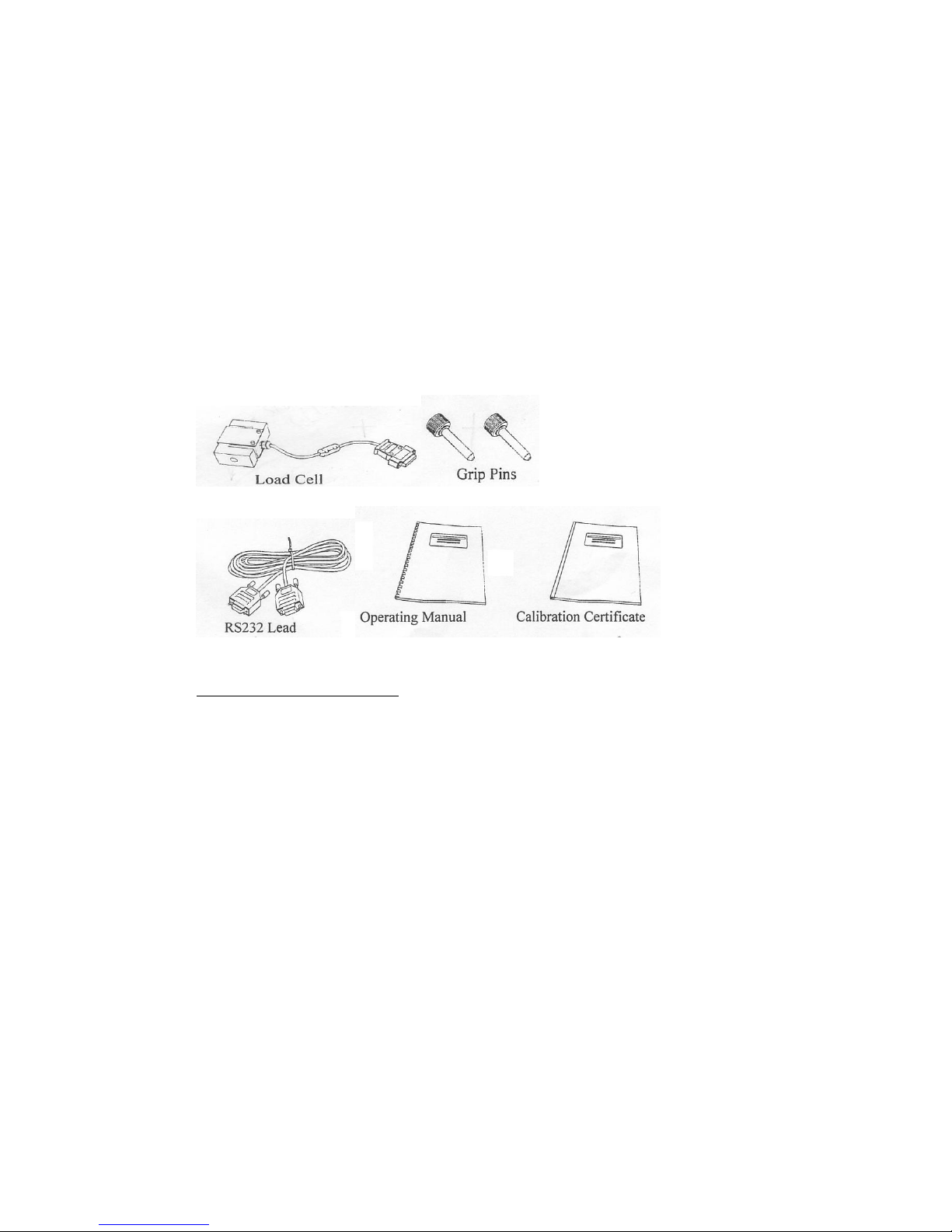
2: CHECKING CONTENTS
The machines are shipped completely assembled except for the optional
accessories. The basic machines are supplied with the following items (please
insure that these are included for the installation):
- Z-Beam Load Cell at or below the maximum capacity of the load frame;
- Two Grip Pins (8 mm) for an adapter;
- operating instruction manual;
- load cell calibration certificate;
- One USB Serial Port Lead for external computer control;
- One 220 V cable.
The following diagrams are to help to identify each item:
Type Number of Machine:
On the backside of each machine you will find a type number (Type Nr.).
Please use it for future reference.
7
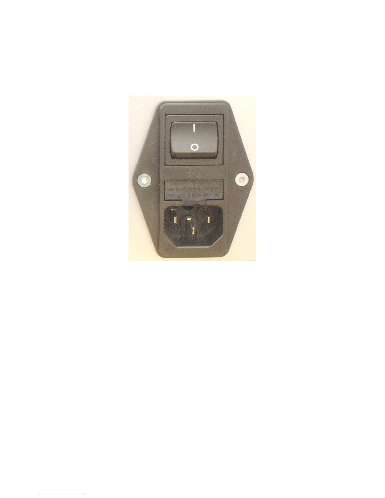
3) POWER ON CHECKS
Power On / Off Switch.
The On (1) and Off (0) power switch is located on the back side of the machine and should be in the
Off (0) position before applying power to the machine.
The picture below indicates the location of the power switch:
1.3 Switching from 220 to 110 volts
Located on the back of the machine, Plug inside allows, that to switch to 110 Volt

8
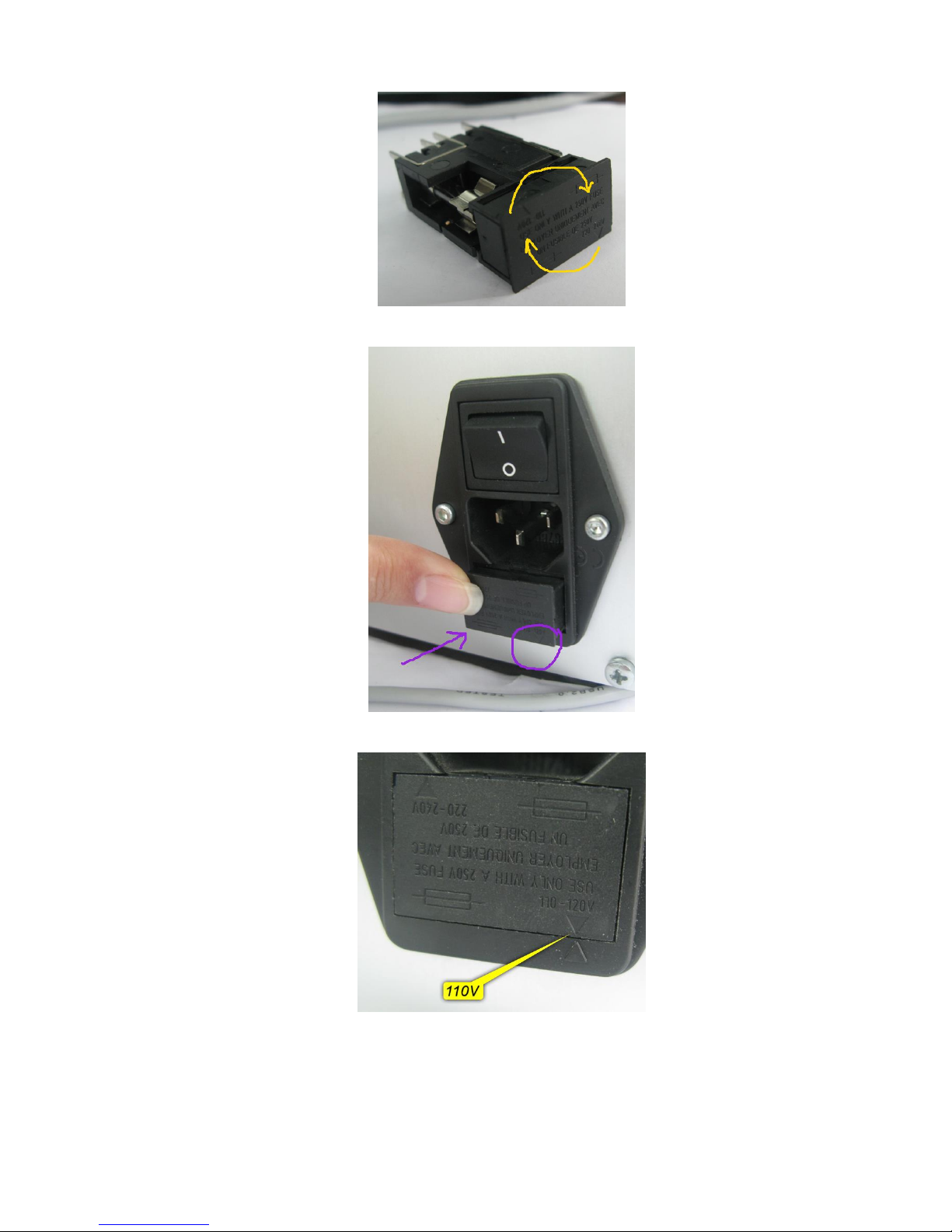
Change 220Volt to 110Volt
How to switch power supply voltage to 110V
Tooling: You need a flat screwdriver.
Look at backside of your machine. Here is a Power Switch. It looks like this:
Voltage Mark indicates what voltage is selected. Here is 220-240V.
With screwdriver open fuse box:
Now rotate this, like it is shown on a picture below:
9
Now insert fuse box into switch. Also be attentive with voltage mark.
Now is selected to 110V. See Picture below. All done.

10
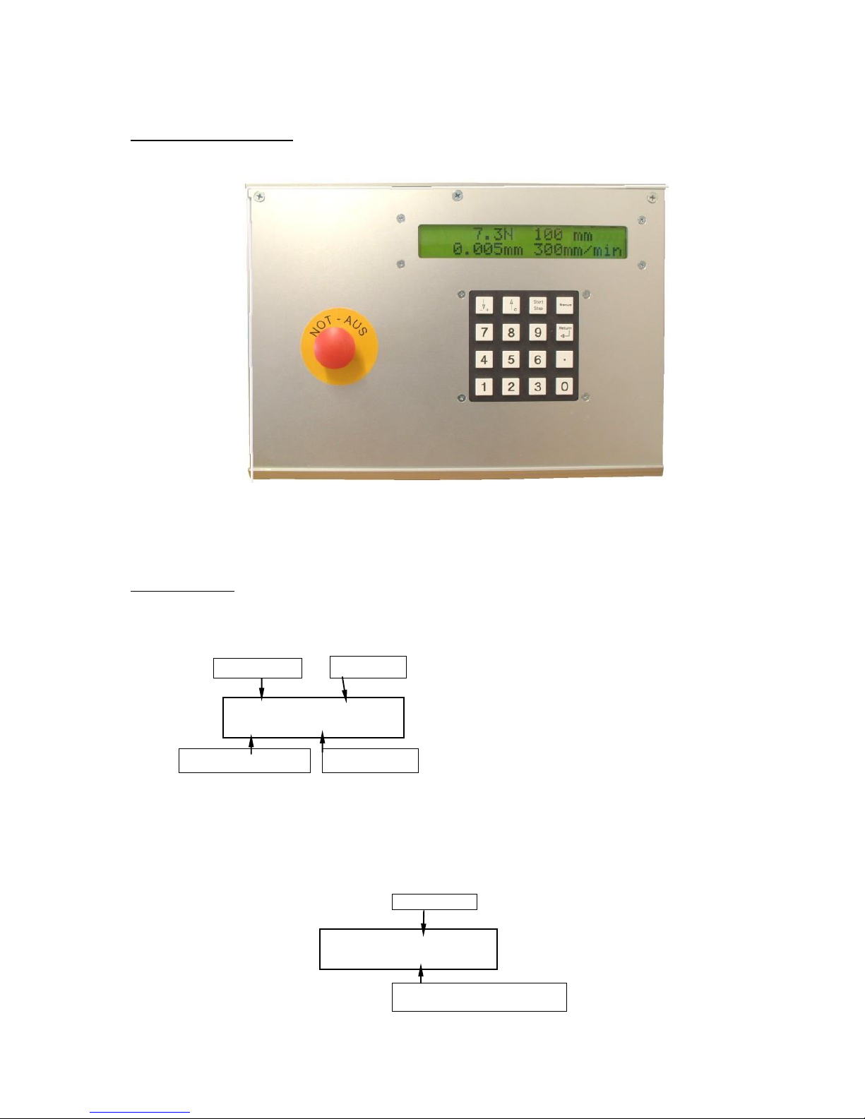
Emergency Stop Push-Button. The Emergency Stop push-button is located on the front panel of the
machine.
To activate the emergency stop you have to push the button. To deactivate the emergency stop turn
the button to the left and the button jumps out.
The picture below indicates the location of the emergency stop push-button:
11
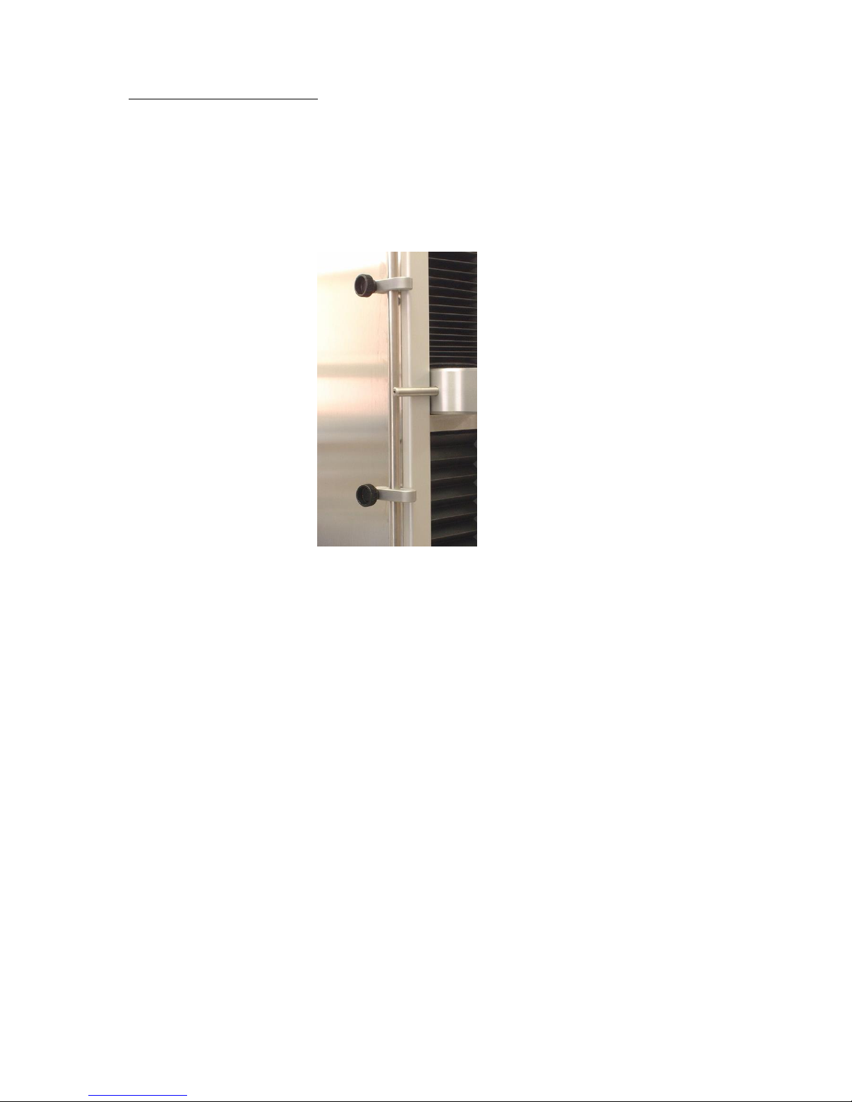
Mechanical Limit Switches.
Before attempting to move the crosshead in either direction it will be required to set the mechanical
crosshead limit switches. The purpose of the limit switches is to reduce the travel of the crosshead
enabling a safe working area. A typical example is to protect the load cell and attachments for
unforeseen over travel and in doing so avoid a collision. These limit switches are located on the left
hand side of the machine.
The figure below shows the location of the mechanical crosshead limit switches:
The limit switches are held in position by a locking screw. To set the limit switch, unlock it by turning
the locking screw in the counterclockwise direction and slide to the required new position. To lock the
limit switch, rotate the locking screw in the clockwise direction. (Note: To eliminate slippage, re-tighten
locking screw securely).
The diagrams below indicate mechanical crosshead limit switches:
Release Upper Limit Switch, move Release Lower Limit Switch, move
crosshead to a new position, slide crosshead to a new position, slide
limit switch to crosshead striker, limit switch to crosshead striker,
Re-tighten. Re-tighten.
12
4) DISPLAY UNIT
Control Display Panel. This unit contains the LCD Display, the Numeric Keypad and
the Emergency Stop push-button.
LCD DISPLAY
When you switch on the machine, you get a message about the Firmware. You will
see the following:
When the test is finished (i.e. when the extension is reached, or the maximum force
is exceeded, or the break of the specimen is detected), you see the maximum force
of the last test.
1435.23 N 50 mm/min
327.12 mm 100 mm
actual force
crosshead displacement
test speed
test extension
F max = 1435.23 N
X max = 345.33 mm
Maximum force
Position where the maximum force
was reached

13
By pressing the [2] key the operator gets the information about the
force at break.
.
F break = 1435.23 N
X break = 345.33 mm
Force at break
Displacement at
break

14
5) Menu Keypad
Numeric Keypad: These keys are used for entering numeric values on the LCDDisplay (Speeds, Extension, etc.).
Crosshead Control Keys: There are two crosshead directional arrows:
The down arrow is used for lowering the crosshead
and for inputting negative values.
The Up arrow is used for raising the crosshead.
This key starts and stops a running test. If the [Start – Stop] key
is pressed during a test, the procedure is interrupted. The same
happens if you press any other key.
With the menu key, the operator can make settings for the next
test. The adjusted settings should be confirmed with the Return
key.
By pressing the [Return] key, the operator stops or returns the
crosshead to zero extension after the test.
This key will zero the Force and Extension display.
S
M

15
This key shows the maximum Force and the referring Extension
of the last test.
This key shows the Force and the Extension of the Rupture.
This key has no function.
This key has no function.
This key is used to enter the configuration menu. This menu is
protected with the password (09122).
This key has no function.
This key has no function.
This key allows switching to constant force mode.
This key has no function.

16
MENU
The [Menu] Key
With this key the operator can make settings for the next test.
The adjusted settings should be confirmed with the [Return] key.
If you press the [Menu] key, you will see the following:
ENDPOS - means “Test Extension”.
The range is possible from 1 mm to 540 mm (for the smallest
version of the machine), except for the length of grips and a
specimen. Positive values mean tensile test; negative values
mean compression test. In order to change from “–“to “+” you
have to press the [Down] key.
V means “Test Speed”.
The range is from 0,5 mm/Min to 500 mm/Min (only positive
values are possible).
F-LIMITS - means “Force Limit”.
The Force Limit can be used to protect tooling rated lower than
the load cell capacity, to end a test when that force is reached.
F-DELTA - means Force Delta.
Force Delta is the sensitivity for detecting the rupture of a
specimen, i.e. the value of 200N means, if during a tensile mode
the load decreases more than 200N/50ms, the rupture is
detected and the test is finished.
If the value is too low, rupture is not detected by the machine and
runs till the end of the set movement
Breaking force, the next interesting force after the maximum force it is difficult to recognize for the
small machine
Therefore, we recommend to setting F-delta to 5% of the maximum force
The expected minimum decline of load within 1/50 second after rupture.
(Between 2 measurement points we measured 50 times per second)
If F-delta is set correctly, the machine stand and the value is displayed
If it too large set the machine drives until the maximum test length is achieved
If it is too small set, the tensile strength will be detected too early - ie. The machine stops although
the candidate has not yet been reached
F-MAN - means Jog Speed.
The range is possible from 1 mm/Min to 500 mm/Min.
M
 Loading...