

Thytronic NA60-MB0 PRON Series, N60-MB2 PRON Series, PRON NA60-MB2, PRON NA60-MB0 User Manual
Page 1

MODBUS PROTOCOL USER GUIDE 3.50
Modbus Communication Protocol User Guide
PRON NA60-MB0
PRON NA60-MB0
PRON NA60-MB0 Remote Setting Manual
Version 3.50
Page: 1 of 59
Page 2

PRON NA60-MB0
Contents
Contents ........................................................................................................................................................................2
1 Modbus RTU communication................................................................................................................................3
1.1
Serial port settings........................................................................................................................................3
1.2
Transmission mode......................................................................................................................................3
1.3
Data Types...................................................................................................................................................3
1.4
Supported functions .....................................................................................................................................4
1.5
Exceptions....................................................................................................................................................4
1.6
Modbus/TCP ................................................................................................................................................5
1.7
Network setting.............................................................................................................................................5
1.8
NTP synchronization ....................................................................................................................................5
2 Logical organization of the protection’s data ........................................................................................................6
2.1
Basic Data Type...........................................................................................................................................6
2.1.1 BIT............................................................................................................................................................6
2.1.2 BYTE........................................................................................................................................................7
2.1.3 UBYTE.....................................................................................................................................................7
2.1.4 WORD......................................................................................................................................................8
2.1.5 UWORD...................................................................................................................................................8
2.1.6 LONG.......................................................................................................................................................9
2.1.7 ULONG ....................................................................................................................................................9
2.1.8 ARR........................................................................................................................................................10
2.1.9 STR........................................................................................................................................................11
2.1.10 CMD.......................................................................................................................................................11
3 How to read the Address Data Table..................................................................................................................12
3.1
Address Data Table....................................................................................................................................12
3.1.1 VAR........................................................................................................................................................12
3.1.2 REF........................................................................................................................................................12
3.1.3 IDX.........................................................................................................................................................12
3.1.4 DIM.........................................................................................................................................................13
3.1.5 TYPE......................................................................................................................................................13
3.1.6 UM..........................................................................................................................................................13
3.1.7 Kv 13
3.1.8 ENUM.....................................................................................................................................................14
3.2
Common properties....................................................................................................................................14
3.2.1 Input state ..............................................................................................................................................14
3.2.2 Output state............................................................................................................................................14
4 Examples ............................................................................................................................................................15
4.1
Example 1. How to read a variable............................................................................................................15
4.2
Example 2. How to read a BIT data type ...................................................................................................16
4.3
Example 3. How to execute a command....................................................................................................16
5 Glossary..............................................................................................................................................................17
6 Appendix A. Address Data Table........................................................................................................................18
Version 3.50
PRON NA60-MB0 Remote Setting Manual
Page: 2 of 59
Page 3

PRON NA60-MB0
Introduction
This Protocol Manual is for use with Thytronic Protective Relays, such as the DMC, NTG and PRO-N series that
support Modbus RTU and Modbus TCP communication protocol.
1 Modbus RTU communication
The Thytronic Protective Relay (TPR) uses a communication protocol called Modbus. A company called Modicon,
for use with their programmable controllers, developed the Modbus protocol. Since that time Modbus has evolved
into common communication protocol in industry and it’s now a “de-facto” standard.
The communication method involves using a master-slave technique, in which there is one master and several
slaves. The TPR is a slave device. Only the master can initiate queries. These queries are directed to an individual
slave device and the appropriate slave responds with the requested data.
There are two transmission modes. These modes are known as RTU (Remote Terminal Unit) and ASCII (American
Standard Code for Information Interchange).
The TPR can be setup in a network of up to 247 slave devices. Each device must have a different address (1-247).
The TPR can be set for RTU mode only.
The MODBUS protocol documentation can be found online at www.modicon.com or www.modbus.org
(document “PDI-MBUS-300 REV J”).
1.1 Serial port settings
To communicate with a TPR, the serial port of the Master has to be configured with the following settings:
Address Baud Rate Parity Stop bits Data bits
1 19200 No 1 8
Table 1 Serial port settings
Remark: Every TPR has a default MODBUS Slave Address set to 1.
1.2 Transmission mode
The transmission mode supported by TPR is RTU.
The ASCII transmission mode is not supported.
1.3 Data Types
A TPR has 4 data table, each of which corresponds to one of the 4 basic Modbus data type. Each table contains up
to 1024 data that can be accessed with the proper function as described in the following table.
table/data type reference information Access Function Code for
Reading
Coils 0X 1 bit Read/Write 0x01 0x05
Discrete Inputs 1X 1 bit Read only 0x02 Input Registers 3X 16 bit Word Read only 0x04 Holding Registers 4X 16 bit Word Read/Write 0x03 0x06, 0x10
Table 2. Modbus Data Type
Function Code for
Writing
Version 3.50
PRON NA60-MB0 Remote Setting Manual
Page: 3 of 59
Page 4

PRON NA60-MB0
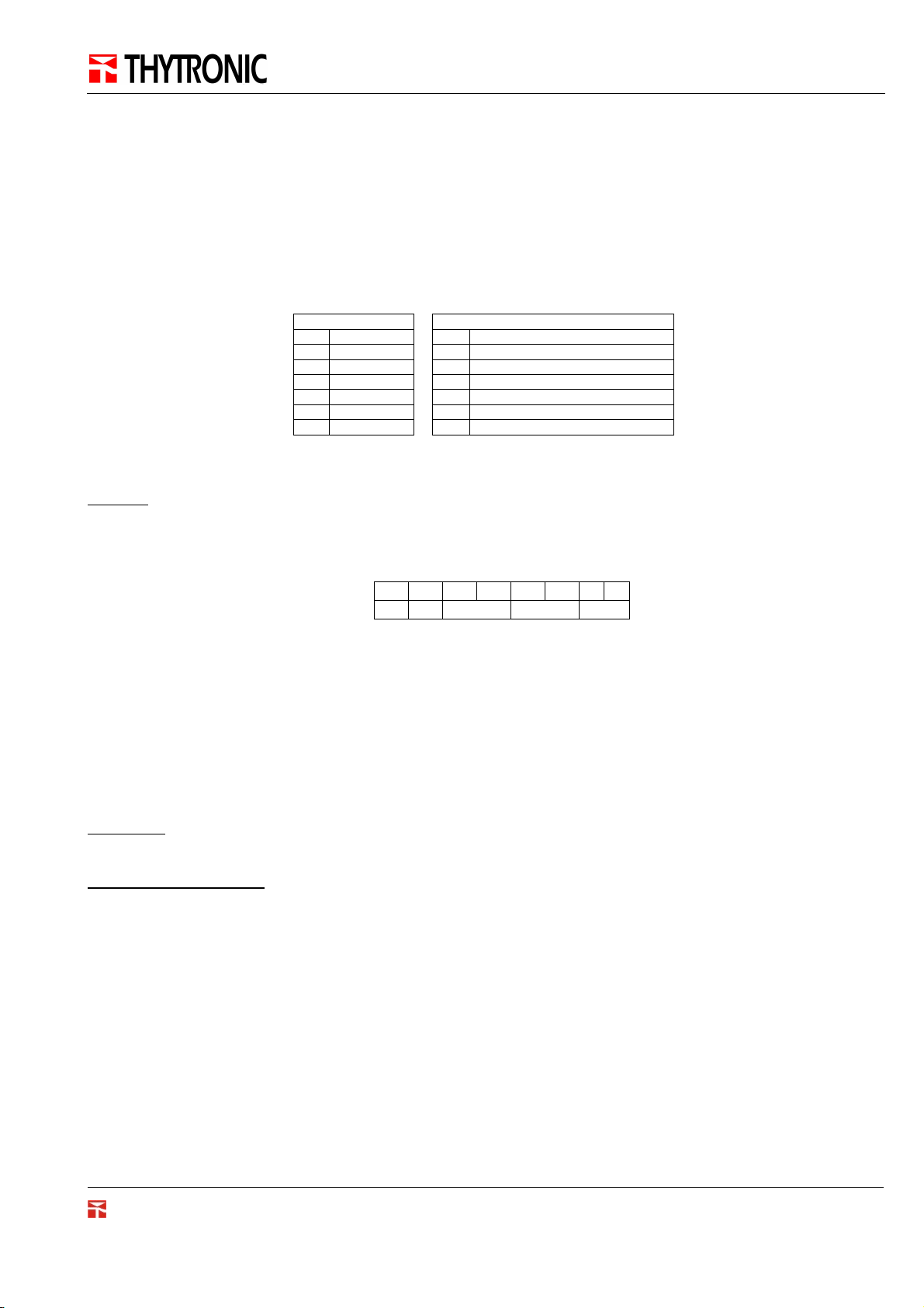
1.4 Supported functions
TPR supports the following Modbus functions:
Code Name
0x01
0x02
0x03
0x04
0x05
0x06
0x0F
0x10
Table 3 Supported Modbus functions
The smallest data that can be exchanged within a Modbus message is the Modbus Register.
A Modbus Register is a 16 bit data in the Big Endian representation, called WORD (W)
Read Coil Status
Read Input Status
Read Holding Registers
Read Input Registers
Force Single Coil
Preset Single Register
Force Multiple Coil
Preset Multiple Registers
W = BH BL
1.5 Exceptions
When a TPR receives a request that can not handle (e.g. the data address doesn’t exists, the function is not
supported, etc.), a special response called Exception is returned to the Master. This message contains the
information needed to recognize the error occurred.
In an Exception message the most significant bit (msb) of the Function field is set to 1.
• Function Code field: in case of exception, the msb is set to 1.
• Data field: this field contains a value related to the kind of error generated by the request.
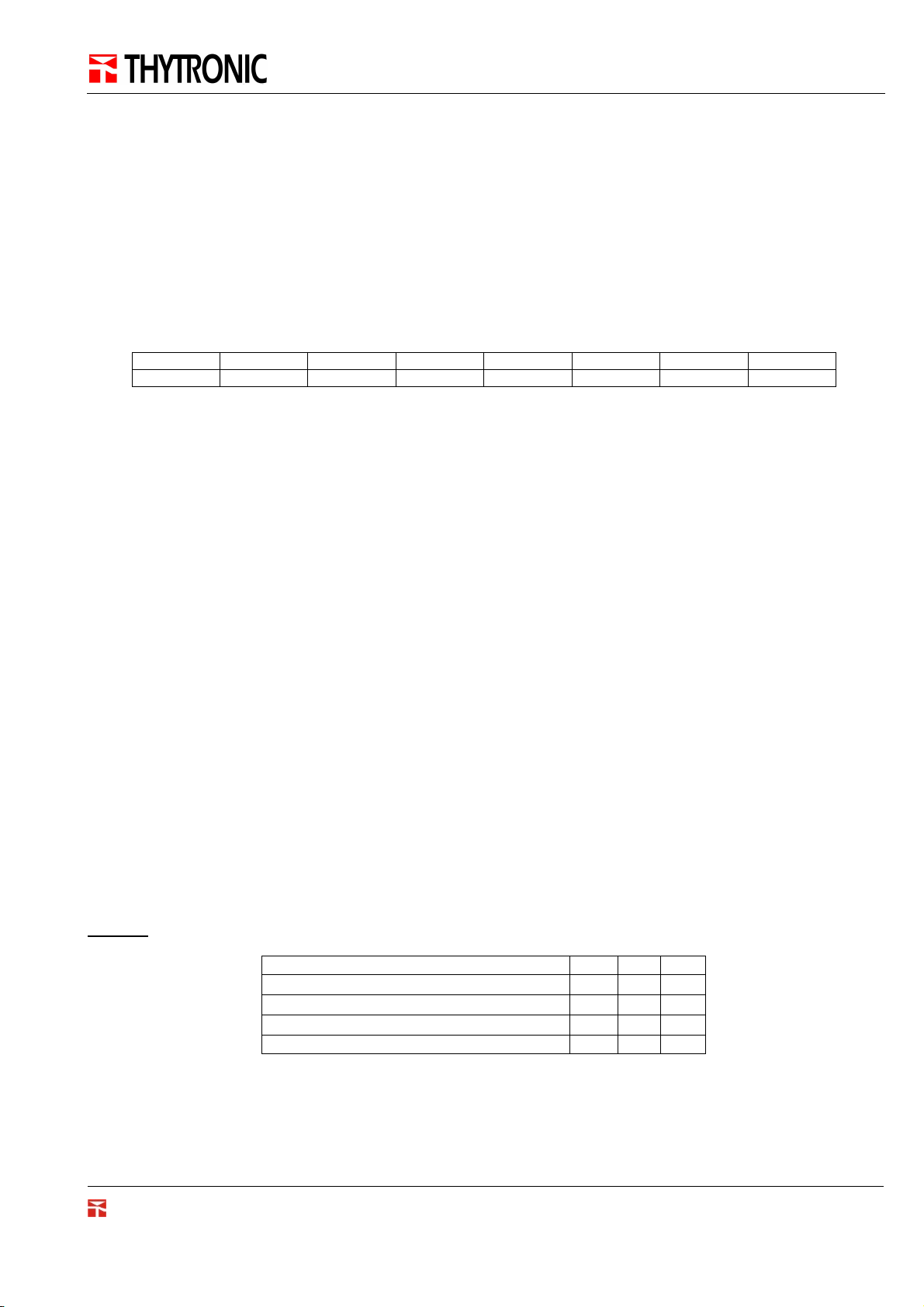
An example of request with exception response could be the following:
04 07 A5 50 00 02 - -
TX
S F ADR DIM CRC
04 87 01 - -
RX
S F DATA CRC
S = Slave Address
F = Function Code
ADR = Modbus Data Address
DIM = Dimension (number of registers)
DATA = data value
CRC = Cyclical Redundancy Code
In this example the function code 07 is not supported by the TPR. The response is an exception message (the msb
of function code F=0x87 is set to 1). The Data field value is 1 and according with the Modbus standard corresponds
to the “Illegal function” exception.
Version 3.50
PRON NA60-MB0 Remote Setting Manual
Page: 4 of 59
Page 5

PRON NA60-MB0
Identifier
Identifier
The next table describes all the exceptions handled by the TPRs.
Code
01 ILLEGAL FUNCTION
02 ILLEGAL DATA ADDRESS
03 ILLEGAL DATA VALUE
04 SLAVE DEVICE FAILURE
05 ACKNOWLEDGE
06 SLAVE DEVICE BUSY
1.6 Modbus/TCP
Modbus/TCP, an extension of Modbus/RTU, defines how Modbus/RTU and Modbus/ASCII messages are encoded
within and transported over TCP/IP-based networks. Modbus/TCP is just as simple to implement and flexible to
apply as the original Modbus/RTU. The specification can be found online at www.modicon.com
Transaction
Name Description
The function code received in the query is not an allowable action for
the slave.
The data address received in the query is not an allowable address for
the slave
A value contained in the query data field is not an allowable value for
the slave
An unrecoverable error occurred while the slave was attempting to
perform the requested action.
The slave has accepted the request and is processing it, but a long
duration of time will be required to do so. This response is returned to
prevent a timeout error from occurring in the master.
The slave is engaged in processing a long-duration program command.
The master should retransmit the message later when the slave is free.
Protocol
Length Field Modbus Frame
CHECKSUM
TCP FRAME
MODBUS FRAME
S F DATA
1.7 Network setting
Every device connected to the TCP/IP network including the TPRs must have a unique IP address. Every TPR has
the following default IP address:
Default IP Address = 200.1.1.135
1.8 NTP synchronization
To synchronize the Real Time Clock of more than one protection at the same time the NTP service is available.
Network Time Protocol (NTP) is a protocol for synchronizing the clocks of computer systems over packet-switched,
variable-latency data networks. NTP uses UDP port 123 as its transport layer. It is designed particularly to resist
the effects of variable latency.
To synchronize all the TPR in a network is sufficient to send a broadcast NTP packet on the network.
The NTP service can be enabled/disabled changing the “NTP synchronization” parameter (Appendix A –
Address Data Table).
More information about the NTP protocol and service can be found online at www.ntp.org
PRON NA60-MB0 Remote Setting Manual
Version 3.50
Page: 5 of 59
Page 6
PRON NA60-MB0
2 Logical organization of the protection’s data
Each TPR has some data that can be read and/or written. These data are grouped in 4 data table.
Data with 1 bit of information (e.g. the state of an output), can be placed in the Discrete Inputs table or in the Coils
table, while data with more than 1 bit of information (e.g. the value of a current), can be placed in the Register
table, sometimes fitting more than one register as described in the following example.
Example: let’s read the value of the variable ”I> Start”. This variable is the first one in the Discrete Input data table.
To read this kind of data the Modbus function 0x02 has to be used. As described in the standard the Modbus
address to access the data is given by IDX-1 = 5 in this case.
To read the data from the Slave address 1 the next request has to be sent:
1x, Discrete Input
n° var n° var
6 I> Start 157 Power frequeny
7 I> Trip 158 Phase current IL1 value – Word L
8 I> Block1 159 Phase current IL1 value – Word H
160 Phase current IL2 value – Word L
161 Phase current IL2 value – Word H
Table 4. Example of data structures
TX
01 02 00 05 00 01 - -
S F ADR DIM CRC
3x, Input Registers
2.1 Basic Data Type
In this chapter all the basic TPR data type and their relationship with the Modbus data type will be described.
2.1.1 BIT
Description:
Variable with 1 bit of information.
Relationship with Modbus:
The information corresponds to the least significant bit (lsb) of the first data byte addressed in the query.
Version 3.50
PRON NA60-MB0 Remote Setting Manual
Page: 6 of 59
Page 7

PRON NA60-MB0
2.1.2 BYTE
Description:
Signed variable with 1 byte (8 bit) of information. Range: -128 +127
Relationship with Modbus:
A BYTE data type is always placed in the Least Significant Byte (LSB) of a Modbus Register (DIM=1).
B 00 B
Byte
Example:
relationship between the data BYTE whose value is 13 (0x0D) and its Modbus representation:
Byte
Modbus
Register
0D 00 0D
Modbus
Register
2.1.3 UBYTE
Description:
Unsigned variable with 1 byte (8 bit) of information. Range: 0 +255
Relationship with Modbus:
A BYTE data type is always placed in the Least Significant Byte (LSB) of a Modbus Register (DIM=1).
B 00 B
UByte
Example:
relationship between the data BYTE whose value is 13 (0x0D) and its Modbus representation:
0D 00 0D
Byte
Modbus
Modbus
Register
Register
Version 3.50
PRON NA60-MB0 Remote Setting Manual
Page: 7 of 59
Page 8

PRON NA60-MB0
2.1.4 WORD
Description:
Signed variable with 2 byte (16 bit) of information. Range: -32.768 +32.767
Relationship with Modbus:
A WORD data type is always placed in a Modbus Register (DIM=1) keeping the representation (Big Endian).
BH BL BH BL
Word
Example:
relationship between the data WORD whose value is 3073 (0x0C01) and its Modbus representation:
0C 01 0C 01
Word
Modbus
Register
Modbus
Register
2.1.5 UWORD
Description:
Unsigned variable with 2 byte (16 bit) of information. Range: 0 +65.535
Relationship with Modbus:
A UWORD data type is always placed in a Modbus Register (DIM=1) keeping the representation (Big Endian).
BH BL BH BL
UWord
Example:
relationship between the data UWORD whose value is 3073 (0x0C01) and its Modbus representation:
0C 01 0C 01
UWord
Modbus
Register
Modbus
Register
Version 3.50
PRON NA60-MB0 Remote Setting Manual
Page: 8 of 59
Page 9

PRON NA60-MB0
2.1.6 LONG
Description:
Signed variable with 4 byte (32 bit) of information. Range: -2.147.483.648 +2.147.483.647
Relationship with Modbus:
A LONG data type is placed in two Modbus Registers (DIM=2). The Least Significant Word of the LONG data type
is placed in the first Modbus register while the Most Significant Word of the LONG data type is placed in the second
Modbus register.
BHH BHL BLH BLL BLH BLL B
WH WL WL WH
Long Modbus Registers
Example:
relationship between the data LONG 66536 (0x103E8) and its value in the Modbus protocol domain:
00 01 03 E8 03 E8 00 01
Long Modbus Registers
HH
BHL
2.1.7 ULONG
Description:
Unsigned variable with 4 byte (32 bit) of information. Range: -0 +4.294.967.295
Relationship with Modbus:
A ULONG data type is placed in two Modbus Registers (DIM=2). The Least Significant Word of the ULONG data
type is placed in the first Modbus register while the Most Significant Word is placed in the second Modbus register.
LHH LHL LLH LLL LLH LLL LHH LHL
WH WL WL WH
ULong Modbus Registers
Example:
relationship between the ULONG data whose value is 66536 (0x103E8) and its Modbus representation:
00 01 03 E8 03 E8 00 01
ULong Modbus Registers
Version 3.50
PRON NA60-MB0 Remote Setting Manual
Page: 9 of 59
Page 10

PRON NA60-MB0
2.1.8 ARR
Description:
Array of BYTE.
Relationship with Modbus:
An ARR data type of length n is placed in N Modbus Registers (N= ceil(n/2) †) keeping the byte ordering. If odd n,
the last byte of ARR is placed in the MSB of the last Modbus register, while the LSB is set to 0
If even n:
B1 B2 Bn B1 B2 B
1 2 n 1 N
Array[n] Modbus Registers
If odd n:
B1 B2 Bn B1 B2 Bn 0
1 2 n 1 N
Array[n] Modbus Registers
Example:
Let’s consider an array with 3 bytes whose values are: (0x01, 0x3A, 0x1F). This array can be placed in
N=ceil(3/2)=ceil(1.5)=2 Modbus registers.
01 3A 1F 01 3A 1F 00
1 2 3 1 2
Array[3] Modbus Registers
Bn
n-1
N = ceil(n/2)
†
The ceil function returns the smallest integer value that is greater than or equal to a number. For example,
ceil(2.3)=3 , ceil(1.5)=2.
Version 3.50
PRON NA60-MB0 Remote Setting Manual
Page: 10 of 59
Page 11

PRON NA60-MB0
2.1.9 STR
Description:
String data type. It’s represented by an array of BYTE. Every byte represents the hexadecimal ASCII code
associated with the character of the string
Relationship with Modbus:
An STR data type of length n is placed in N Modbus Registers (N= ceil(n/2) †) keeping the byte ordering. If odd n,
the last byte is placed in the MSB of the last Modbus register. A zero padding operation (with char ‘\0’) is necessary
for every writing operation where the length of the string is lower than the number of bytes contained in the Modbus
registers.
If even n:
C1 C2 Cn C1 C2 C
1 2 n 1 N
String[n] Modbus Registers
If odd n:
C1 C2 Cn C1 C2 Cn ‘\0’
1 2 n 1 N
String[n] Modbus Registers
Example:
Let’s assume “Relay reference name” is a STRING variable whose length is 8 characters, its Modbus address is
0x0029 and its dimension is 4 Modbus registers. Let’s set its value to “NAxx”.
First of all the ASCII code in hexadecimal notation for each character of the string “NA10” is equal to 0x4E417878
An example of write request could be the following:
01 10 00 29 00 05 10 4E 41 78 78 00 00 00 00 - -
TX
S F ADR DIM B DATA1 DATA2 DATA3 DATA4 CRC
‘N’ ‘A’ ‘x’ ‘x’ ‘\0’ ‘\0’ ‘\0’ ‘\0’
Remark. A zero padding operation is necessary because the length of the string “DMC901” is lower than the length
of the RACK_TYPE variable.
Cn
n-1
N = ceil(n/2)
2.1.10 CMD
Description:
This type of data represents a command.
Every Command corresponds to a Coil data type. To execute the command, the value of the associated Coil has to
be set to 1 with the Modbus function 0x05.
†
The ceil function returns the smallest integer value that is greater than or equal to a number. For example,
ceil(2.3)=3 , ceil(1.5)=2.
PRON NA60-MB0 Remote Setting Manual
Version 3.50
Page: 11 of 59
Page 12
PRON NA60-MB0
Table
5
. Address Data Table’s field
3 How to read the Address Data Table
All the information necessary to read/write data from/to a TPR is contained in the Address Data Table (see
Appendix A).
3.1 Address Data Table
Now a description of all the Address Data Table’s fields is given:
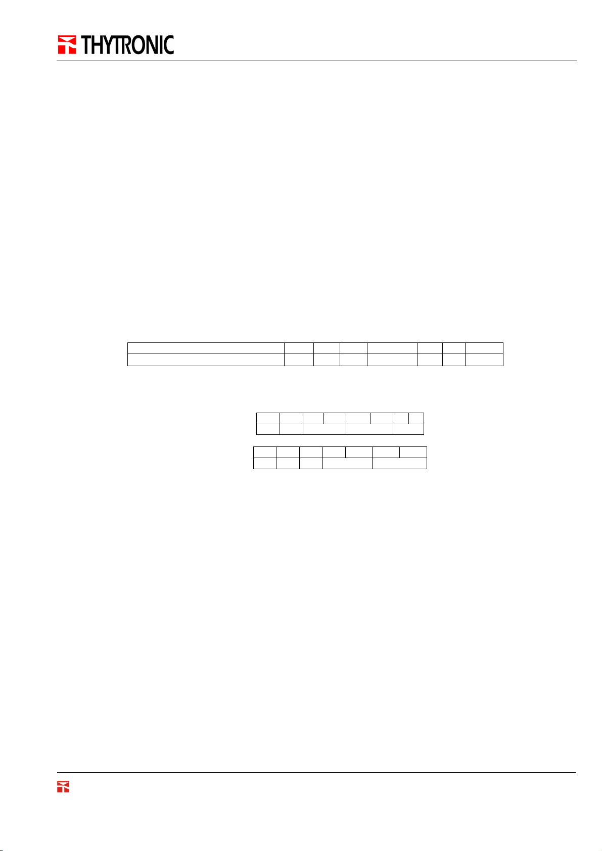
3.1.1 VAR
The VAR field contains the description of the variable.
An example of VAR fields could be: “Relay phase nominal current - In ”, “Relay reference name” or “I> Trip”.
VAR REF IDX DIM TYPE UM KV ENUM
3.1.2 REF
The REF field tells which data table the variable is stored in.
The REF field can assume one of the following values:
• 0x: data stored in the COIL table
• 1x: data stored in the DISCRETE INPUT table
• 3x: data stored in the INPUT REGISTER table
• 4x: data stored in the HOLDING REGISTER table
3.1.3 IDX
The IDX field represents the position of the table (specified by REF) in which the variable VAR is stored.
The IDX value is related to the Modbus address of the variable. The relationship between IDX and Modbus address
is the following:
MB address = IDX - 1
Example: let’s consider the following Address Data Table
VAR REF IDX DIM
Relay phase nominal current - In
Relay reference name
I> Trip
Let’s see that the variable “Relay phase nominal current - In” is the 50th variable stored in the Input Registers
table (reference 3x) and its dimension is 1 Modbus register (DIM=1).
3x 50 1
3x 42 8
1x 7 1
PRON NA60-MB0 Remote Setting Manual
Version 3.50
Page: 12 of 59
Page 13

PRON NA60-MB0
3.1.4 DIM
The DIM field is the number of Modbus registers necessary to contain the VAR data.
Example: let’s read the value of the variable “Relay phase nominal current - In ”.
From the previous table we see that the reference is 4x for which the function 0x03 has to be used for reading.
The Modbus address is IDX-1=50-1=49.
The request for reading is the following:
01 03 00 31 00 01 - -
TX
S F ADR DIM CRC
3.1.5 TYPE
The TYPE field specifies the basic data type associated with VAR, as described in chapter 2.1.
3.1.6 UM
The UM field specifies the Unit of Measure of the variable.
If UM is empty, it means that the Unit is just a number.
3.1.7 Kv
The Kv field contains the scale factor that has to be applied to the variable to obtain the real value. If Kv is not
equal to 1, the value of the variable must be divided by Kv.
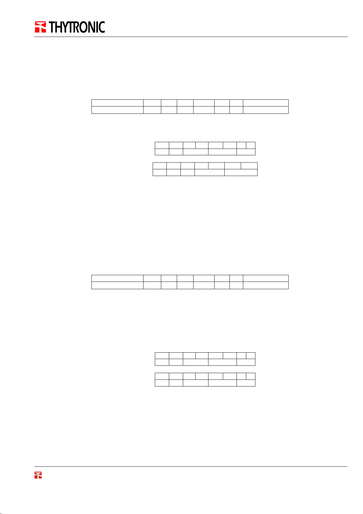
Example: let’s consider the following address data table
VAR REF IDX DIM TYPE UM KV ENUM
Phase current IL1 - Value 3x 159 2 LONG In 16000
Let’s read the “Phase current IL1 - Value “ from the Slave address 1.
01 04 00 9E 00 02 - -
TX
S F ADR DIM CRC
Let’s assume the following response:
RX
The TYPE field is necessary to decode the right value returned from the Modbus response, as described in chapter
2.1. The decoded value contained in the response is 0x0003A980 = 240000. Kv=16000 means that the value of the
variable has to be divided by 16000. UM specify the Unit. The “Phase current IL1 – Value” is equal to 15 In.
01 04 04 A9 80 00 03 - -
S F B DATA1 DATA2 CRC
LONG
VALL VALH
Version 3.50
PRON NA60-MB0 Remote Setting Manual
Page: 13 of 59
Page 14

PRON NA60-MB0
3.1.8 ENUM
The ENUM field, whenever is defined, contains the meaning of all possible values assumed by the variable.
3.2 Common properties
Some common properties are now described for a better understanding.
3.2.1 Input state
• State
It’s the physical state of the Input: 0 or 1 (OFF or ON)
3.2.2 Output state
• State
It’s the logical state of the output: 0 or 1 (OFF or ON); could not correspond with its physical state
• Fail
It’s the Coil Failure Status: 0 or 1 (OFF=”OK” o ON=”Fault”).
Version 3.50
PRON NA60-MB0 Remote Setting Manual
Page: 14 of 59
Page 15
PRON NA60-MB0
4 Examples
For all the examples, the following symbols are assumed:
S = Slave Modbus address (1-247)
F = Modbus Function code (1,2,3,4,5,6,15,16)
B = number of byte in the DATA field
ADR = Modbus DATA address
DIM = number of Modbus DATA address
CRC = Cyclical Redundancy Check
DATAx = register x of DATA field
VALx = value x of the variable
4.1 Example 1. How to read a variable
Let’s read from the Slave address 1 the value of the “Relay phase nominal current - In ”.
From the Address Data Table (Appendix A) we find out the following information;
VAR REF IDX DIM TYPE UM Kv ENUM
Relay phase nominal current - In 3x 50 1 UWORD A 1
The REF field value specify an Input Register (3x), so the function 0x04 is used for reading. From the IDX the
Modbus address is derived: Modbus address = IDX -1 = 50 - 1 = 49. DIM specify the number of register to be read.
TX
RX
The TYPE field value is equal to UWORD. Applying the rules described in the chapter 2.1, the following value is
obtained
Il UM field specify the Unit of measure that is “Ampere”, while Kv = 1 means that the value doesn’t need to be
scaled. The “Relay phase nominal current – In” is equal to 5A.
01 04 00 3E 00 02 - -
S F ADR DIM CRC
01 04 04 00 05 - -
S F B DATA CRC
VAL = 0x0005= 5.
Version 3.50
PRON NA60-MB0 Remote Setting Manual
Page: 15 of 59
Page 16
PRON NA60-MB0
4.2 Example 2. How to read a BIT data type
Let’s read from the Slave address 1 the variable “I> Trip”.
From the Address Data Table (Appendix A) we find out the following information;
VAR REF IDX DIM TYPE UM Kv ENUM
I> Trip 1x 7 1 BIT 0=OFF, 1=ON
The REF field value specify a Discrete Input (1x), so the function 0x02 is used for reading. From the IDX the
Modbus address is derived: Modbus address = IDX -1 = 7 - 1 = 6. DIM specify the number of register to be read.
TX
RX
The TYPE field value is equal to BIT. Applying the rules described in the chapter 2.1, the following value is
obtained
The ENUM field specifies the meaning of the value. In this case, the value 1 corresponds to the “ON” state and it
means that a Trip has occurred on the first threshold of the 51 function.
01 02 00 06 00 01 - -
S F ADR DIM CRC
01 02 01 00 01 - -
S F B VAL CRC
VAL = 1.
4.3 Example 3. How to execute a command
Let’s execute the command “Reset events” on the Slave address 1.
From the Address Data Table (Appendix A) we find out the following information;
VAR REF IDX DIM TYPE UM Kv ENUM
Reset LEDs 0x 2 1 CMD 0=OFF, 1=ON
The TYPE field value specifies a Command (CMD). As described in chapter 2.1, to execute the command, it is
necessary to set its value to 1.
The REF field value specify a Coil (0x), so the function 0x05 is used for writing. From the IDX the Modbus address
is derived: Modbus address = IDX -1 = 2 - 1 = 1
The Response message is known as an “Acknowledge” because it’s an echo of the request, and it means that the
Coil has been set:
TX
RX
01 05 00 01 FF 00 - -
S F ADR DATA CRC
01 05 00 01 FF 00 - -
S F ADR DATA CRC
Version 3.50
PRON NA60-MB0 Remote Setting Manual
Page: 16 of 59
Page 17

5 Glossary
BH Most significative Byte of a Word data (Higher byte)
BL Least significative Byte of a Word data (Lower byte)
LSB Least Significative Byte
lsb least significative bit
MSB Most Significative Byte
msb Most significative bit
NTP Network Time Protocol
RTU Remote Terminal Unit
TPR Thytronic Protective Relay
WH Most significative Word of a Long data (Higher word)
WL Least significative Word of a Long data (Lower word)
PRON NA60-MB0
Version 3.50
PRON NA60-MB0 Remote Setting Manual
Page: 17 of 59
Page 18
PRON NA60-MB0
6 Appendix A. Address Data Table
VAR REF IDX DIM TYPE Range Um Kv ENUM
Commands
Set RTC 0x 1 1 CMD 0=OFF, 1=ON
Reset CB Open counter 0x 2 1 CMD 0=OFF, 1=ON
Reset LEDs 0x 3 1 CMD 0=OFF, 1=ON
Reset CB time action 0x 4 1 CMD 0=OFF, 1=ON
Reset MTV 0x 5 1 CMD 0=OFF, 1=ON
Reset Breaking currents SumI2t 0x 6 1 CMD 0=OFF, 1=ON
Reset Breaking currents SumI 0x 7 1 CMD 0=OFF, 1=ON
Reset partial counters 0x 8 1 CMD 0=OFF, 1=ON
Thermal image presetting 0x 9 1 CMD 0=OFF, 1=ON
Fault reading 0x 10 1 CMD 0=OFF, 1=ON
Reset faults 0x 11 1 CMD 0=OFF, 1=ON
Reset faults identifier 0x 12 1 CMD 0=OFF, 1=ON
Events reading 0x 13 1 CMD 0=OFF, 1=ON
Reset events 0x 14 1 CMD 0=OFF, 1=ON
Reset event identifier 0x 15 1 CMD 0=OFF, 1=ON
Open CB 0x 16 1 CMD 0=OFF, 1=ON
Close CB 0x 17 1 CMD 0=OFF, 1=ON
Test-off 0x 18 1 CMD 0=OFF, 1=ON
Test-on 0x 19 1 CMD 0=OFF, 1=ON
Reset on demand measures 0x 20 1 CMD 0=OFF, 1=ON
Reset on energy measures 0x 21 1 CMD 0=OFF, 1=ON
PLC2 Command - 1 0x 22 1 CMD 0=OFF, 1=ON
PLC2 Command - 2 0x 23 1 CMD 0=OFF, 1=ON
Version 3.50
PRON NA60-MB0 Remote Setting Manual
Page: 18 of 59
Page 19

PRON NA60-MB0
VAR REF IDX DIM TYPE Range Um Kv ENUM
Commands
Day 4x 1 1 UWORD 1,31,1 1
Month 4x 2 1 UWORD 1,12,1 1
Year 4x 3 1 UWORD 2000,2099,1 1
Hour 4x 4 1 UWORD 0,23,1 1
Minute 4x 5 1 UWORD 0,59,1 1
Second 4x 6 1 UWORD 0,59,1 1
Testing rele 4x 7 1 WORD 0="K1",1="K2",2="K3",3="K4"
PLC2 Holding register - 1 4x 8 1 UWORD 1,65535,1 1
PLC2 Holding register - 2 4x 9 1 UWORD 1,65535,1 1
Info
Code 3x 1 6 STR
Serial number 3x 7 2 LONG 1
Application sw release - 3x 9 6 not defined
Base sw release 3x 15 6 STR
DSP fw identifier 3x 21 1 UWORD 1
DSP fw release 3x 22 6 STR
Communication
Address 3x 28 1 UBYTE 1
Remote Ethernet IP host address 3x 29 8 STR
Remote Ethernet IP Net Mask 3x 37 8 STR
Remote Ethernet Autonegotiation 1x 1 1 BIT 0=OFF, 1=ON
Enable 1x 2 1 BIT 0=OFF, 1=ON
,4="K5",5="K6",6="K7",7="K8
",8="K9",9="K10"
Version 3.50
PRON NA60-MB0 Remote Setting Manual
Page: 19 of 59
Page 20

PRON NA60-MB0
VAR REF IDX DIM TYPE Range Um Kv ENUM
Rated nominal values
Relay reference name 3x 45 10 STR
Relay phase nominal current - In 3x 55 2 ULONG A 1
Relay residual nominal current - IEn 3x 57 2 ULONG A 1
Phase CT primary nominal current - Inp 3x 59 2 ULONG A 1
Residual CT primary nominal current - IEnp 3x 61 2 ULONG A 1
Relay nominal voltage ( phase to phase ) - Un 3x 63 2 ULONG V 1
Line VT primary nominal voltage ( phase to phase ) - Unp 3x 65 2 ULONG V 1
Relay residual nominal voltage ( direct measurement ) - UEn 3x 67 2 ULONG V 1
Residual primary nominal voltage ( phase to phase ) * 1.73 UEnp
Relay nominal frequency - fn 3x 71 2 ULONG Hz 1
Measurements reading mode 3x 73 1 WORD 0="RELATIVE",1="PRIMARY
Profile selection
Profile 3x 74 1 WORD 0="A",1="B"
Clock
Day 3x 75 1 UWORD 1
Month 3x 76 1 UWORD 1
Year 3x 77 1 UWORD 1
Hour 3x 78 1 UWORD 1
Minute 3x 79 1 UWORD 1
Second 3x 80 1 UWORD 1
3x 69 2 ULONG V 1
"
Version 3.50
PRON NA60-MB0 Remote Setting Manual
Page: 20 of 59
Page 21

PRON NA60-MB0
VAR REF IDX DIM TYPE Range Um Kv ENUM
READINGS
Diagnostic
MINOR Fail alarm 1x 3 1 BIT 0=NO, 1=YES
Protection and controls 1x 4 1 BIT 0=OUT OF SERVICE, 1=ON
System diagnostic 3x 81 1 WORD 0="OK",1="FATAL",2="MAJO
Device diagnostic 1x 5 1 BIT 0=OK, 1=NOT OK
Program diagnostic 3x 82 1 WORD 0="OK",1="NOT
Data-base boot 3x 83 1 WORD 0="OK",1="NOT
Data-base run-time 3x 84 1 WORD 0="OK",1="NOT
DSP boot 3x 85 1 WORD 0="OK",1="NOT
DSP run-time 3x 86 1 WORD 0="OK",1="NOT
Memory boot 3x 87 1 WORD 0="OK",1="NOT
Memory run-time 3x 88 1 WORD 0="OK",1="NOT
Serial flash startup 3x 89 3 STR
Serial flash run-time 3x 92 3 STR
Data Bus heavy 3x 95 1 WORD 0="OK",1="NOT
Data Bus minor 3x 96 1 WORD 0="OK",1="NOT
Protection I/O assigned verify startup 3x 97 1 WORD 0="OK",1="NOT
Protection I/O assigned verify run-time major 3x 98 1 WORD 0="OK",1="NOT
Protection I/O assigned verify run-time minor 3x 99 1 WORD 0="OK",1="NOT
SERVICE
R",3="MINOR"
OK",2="Disappeared"
OK",2="Disappeared"
OK",2="Disappeared"
OK",2="Disappeared"
OK",2="Disappeared"
OK",2="Disappeared"
OK",2="Disappeared"
OK",2="Disappeared"
OK",2="Disappeared"
OK",2="Disappeared"
OK",2="Disappeared"
OK",2="Disappeared"
Version 3.50
PRON NA60-MB0 Remote Setting Manual
Page: 21 of 59
Page 22

PRON NA60-MB0
VAR REF IDX DIM TYPE Range Um Kv ENUM
Diagnostic
MMI module - Boot 3x 100 1 WORD 0="NOT OK: Undefined
MMI module - Run-time 3x 101 1 WORD 0="NOT OK: Undefined
MRI module - Boot 3x 10² 1 WORD 0="NOT OK: Undefined
MRI module - Run-time 3x 10³ 1 WORD 0="NOT OK: Undefined
MID16-1 module - Boot 3x 10⁴ 1 WORD 0="NOT OK: Undefined
MID16-1 module - Run-time 3x 10⁵ 1 WORD 0="NOT OK: Undefined
module",1="OK",2="NOT OK:
missing module",3="NOT OK:
incompatible
module",4="OK",5="NOT
OK",6="OFF",7="OFF:
Remove module"
module",1="OK",2="NOT OK:
missing module",3="NOT OK:
incompatible
module",4="OK",5="NOT
OK",6="OFF",7="OFF:
Remove module"
module",1="OK",2="NOT OK:
missing module",3="NOT OK:
incompatible
module",4="OK",5="NOT
OK",6="OFF",7="OFF:
Remove module"
module",1="OK",2="NOT OK:
missing module",3="NOT OK:
incompatible
module",4="OK",5="NOT
OK",6="OFF",7="OFF:
Remove module"
module",1="OK",2="NOT OK:
missing module",3="NOT OK:
incompatible
module",4="OK",5="NOT
OK",6="OFF",7="OFF:
Remove module"
module",1="OK",2="NOT OK:
missing module",3="NOT OK:
incompatible
module",4="OK",5="NOT
OK",6="OFF",7="OFF:
Remove module"
Version 3.50
PRON NA60-MB0 Remote Setting Manual
Page: 22 of 59
Page 23

PRON NA60-MB0
VAR REF IDX DIM TYPE Range Um Kv ENUM
Diagnostic
MID16-2 module - Boot 3x 10⁶ 1 WORD 0="NOT OK: Undefined
MID16-2 module - Run-time 3x 10⁷ 1 WORD 0="NOT OK: Undefined
PT100 module - Boot 3x 10⁸ 1 WORD 0="NOT OK: Undefined
PT100 module - Run-time 3x 10⁹ 1 WORD 0="NOT OK: Undefined
MCI module (4...20mA) - Boot 3x 110 1 WORD 0="NOT OK: Undefined
MCI module (4...20mA) - Run-time 3x 111 1 WORD 0="NOT OK: Undefined
module",1="OK",2="NOT OK:
missing module",3="NOT OK:
incompatible
module",4="OK",5="NOT
OK",6="OFF",7="OFF:
Remove module"
module",1="OK",2="NOT OK:
missing module",3="NOT OK:
incompatible
module",4="OK",5="NOT
OK",6="OFF",7="OFF:
Remove module"
module",1="OK",2="NOT OK:
missing module",3="NOT OK:
incompatible
module",4="OK",5="NOT
OK",6="OFF",7="OFF:
Remove module"
module",1="OK",2="NOT OK:
missing module",3="NOT OK:
incompatible
module",4="OK",5="NOT
OK",6="OFF",7="OFF:
Remove module"
module",1="OK",2="NOT OK:
missing module",3="NOT OK:
incompatible
module",4="OK",5="NOT
OK",6="OFF",7="OFF:
Remove module"
module",1="OK",2="NOT OK:
missing module",3="NOT OK:
incompatible
module",4="OK",5="NOT
OK",6="OFF",7="OFF:
Remove module"
Version 3.50
PRON NA60-MB0 Remote Setting Manual
Page: 23 of 59
Page 24

PRON NA60-MB0
VAR REF IDX DIM TYPE Range Um Kv ENUM
PROTECTIONS
Thermal protection with RTD thermometric probes - 26
Alarm ThAL1 1x 6 1 BIT 0=OFF, 1=ON
Trip Th>1 1x 7 1 BIT 0=OFF, 1=ON
Alarm ThAL2 1x 8 1 BIT 0=OFF, 1=ON
Trip Th>2 1x 9 1 BIT 0=OFF, 1=ON
Alarm ThAL3 1x 10 1 BIT 0=OFF, 1=ON
Trip Th>3 1x 11 1 BIT 0=OFF, 1=ON
Alarm ThAL4 1x 12 1 BIT 0=OFF, 1=ON
Trip Th>4 1x 13 1 BIT 0=OFF, 1=ON
Alarm ThAL5 1x 14 1 BIT 0=OFF, 1=ON
Trip Th>5 1x 15 1 BIT 0=OFF, 1=ON
Alarm ThAL6 1x 16 1 BIT 0=OFF, 1=ON
Trip Th>6 1x 17 1 BIT 0=OFF, 1=ON
Alarm ThAL7 1x 18 1 BIT 0=OFF, 1=ON
Trip Th>7 1x 19 1 BIT 0=OFF, 1=ON
Alarm ThAL8 1x 20 1 BIT 0=OFF, 1=ON
Trip Th>8 1x 21 1 BIT 0=OFF, 1=ON
Diag PT100 1x 22 1 BIT 0=OFF, 1=ON
Undervoltage - 27
Start U< 1x 23 1 BIT 0=OFF, 1=ON
Trip U< 1x 24 1 BIT 0=OFF, 1=ON
BLK1 U< 1x 25 1 BIT 0=OFF, 1=ON
Start U<< 1x 26 1 BIT 0=OFF, 1=ON
Trip U<< 1x 27 1 BIT 0=OFF, 1=ON
BLK1 U<< 1x 28 1 BIT 0=OFF, 1=ON
Version 3.50
PRON NA60-MB0 Remote Setting Manual
Page: 24 of 59
Page 25

PRON NA60-MB0
VAR REF IDX DIM TYPE Range Um Kv ENUM
Thermal image - 49
Alarm DthAL1 1x 29 1 BIT 0=OFF, 1=ON
BLK1 DthAL1 1x 30 1 BIT 0=OFF, 1=ON
BLK2IN DthAL1 1x 31 1 BIT 0=OFF, 1=ON
BLK4IN DthAL1 1x 32 1 BIT 0=OFF, 1=ON
Alarm DthAL2 1x 33 1 BIT 0=OFF, 1=ON
BLK1 DthAL2 1x 34 1 BIT 0=OFF, 1=ON
BLK2IN DthAL2 1x 35 1 BIT 0=OFF, 1=ON
BLK4IN DthAL2 1x 36 1 BIT 0=OFF, 1=ON
Trip Dth> 1x 37 1 BIT 0=OFF, 1=ON
BLK1 Dth> 1x 38 1 BIT 0=OFF, 1=ON
BLK2IN Dth> 1x 39 1 BIT 0=OFF, 1=ON
BLK4IN Dth> 1x 40 1 BIT 0=OFF, 1=ON
CLP Dth 1x 41 1 BIT 0=OFF, 1=ON
Phase overcurrent - 50/51
Start I> 1x 42 1 BIT 0=OFF, 1=ON
Trip I> 1x 43 1 BIT 0=OFF, 1=ON
BLK1 I> 1x 44 1 BIT 0=OFF, 1=ON
BLK2IN I> 1x 45 1 BIT 0=OFF, 1=ON
BLK4IN I> 1x 46 1 BIT 0=OFF, 1=ON
CLP I> 1x 47 1 BIT 0=OFF, 1=ON
Start I>> 1x 48 1 BIT 0=OFF, 1=ON
Trip I>> 1x 49 1 BIT 0=OFF, 1=ON
BLK1 I>> 1x 50 1 BIT 0=OFF, 1=ON
BLK2IN I>> 1x 51 1 BIT 0=OFF, 1=ON
BLK4IN I>> 1x 52 1 BIT 0=OFF, 1=ON
CLP I>> 1x 53 1 BIT 0=OFF, 1=ON
Start I>>> 1x 54 1 BIT 0=OFF, 1=ON
Trip I>>> 1x 55 1 BIT 0=OFF, 1=ON
BLK1 I>>> 1x 56 1 BIT 0=OFF, 1=ON
BLK2IN I>>> 1x 57 1 BIT 0=OFF, 1=ON
BLK4IN I>>> 1x 58 1 BIT 0=OFF, 1=ON
CLP I>>> 1x 59 1 BIT 0=OFF, 1=ON
Version 3.50
PRON NA60-MB0 Remote Setting Manual
Page: 25 of 59
Page 26

PRON NA60-MB0
VAR REF IDX DIM TYPE Range Um Kv ENUM
Residual overcurrent - 50N/51N
Start IE> 1x 60 1 BIT 0=OFF, 1=ON
Trip IE> 1x 61 1 BIT 0=OFF, 1=ON
BLK1 IE> 1x 62 1 BIT 0=OFF, 1=ON
BLK2IN IE> 1x 63 1 BIT 0=OFF, 1=ON
BLK4IN IE> 1x 64 1 BIT 0=OFF, 1=ON
CLP IE> 1x 65 1 BIT 0=OFF, 1=ON
Start IE>> 1x 66 1 BIT 0=OFF, 1=ON
Trip IE>> 1x 67 1 BIT 0=OFF, 1=ON
BLK1 IE>> 1x 68 1 BIT 0=OFF, 1=ON
BLK2IN IE>> 1x 69 1 BIT 0=OFF, 1=ON
BLK4IN IE>> 1x 70 1 BIT 0=OFF, 1=ON
CLP IE>> 1x 71 1 BIT 0=OFF, 1=ON
Start IE>>> 1x 72 1 BIT 0=OFF, 1=ON
Trip IE>>> 1x 73 1 BIT 0=OFF, 1=ON
BLK1 IE>>> 1x 74 1 BIT 0=OFF, 1=ON
BLK2IN IE>>> 1x 75 1 BIT 0=OFF, 1=ON
BLK4IN IE>>> 1x 76 1 BIT 0=OFF, 1=ON
CLP IE>>> 1x 77 1 BIT 0=OFF, 1=ON
Overvoltage - 59
Start U> 1x 78 1 BIT 0=OFF, 1=ON
Trip U> 1x 79 1 BIT 0=OFF, 1=ON
BLK1 U> 1x 80 1 BIT 0=OFF, 1=ON
Start U>> 1x 81 1 BIT 0=OFF, 1=ON
Trip U>> 1x 82 1 BIT 0=OFF, 1=ON
BLK1 U>> 1x 83 1 BIT 0=OFF, 1=ON
Residual overvoltage - 59N
Start UE> 1x 84 1 BIT 0=OFF, 1=ON
Trip UE> 1x 85 1 BIT 0=OFF, 1=ON
BLK1 UE> 1x 86 1 BIT 0=OFF, 1=ON
Start UE>> 1x 87 1 BIT 0=OFF, 1=ON
Trip UE>> 1x 88 1 BIT 0=OFF, 1=ON
BLK1 UE>> 1x 89 1 BIT 0=OFF, 1=ON
Version 3.50
PRON NA60-MB0 Remote Setting Manual
Page: 26 of 59
Page 27

PRON NA60-MB0
VAR REF IDX DIM TYPE Range Um Kv ENUM
Directional phase overcurrent - 67
Start IPD> 1x 90 1 BIT 0=OFF, 1=ON
Trip IPD> 1x 91 1 BIT 0=OFF, 1=ON
BLK1 IPD> 1x 92 1 BIT 0=OFF, 1=ON
BLK2IN IPD> 1x 93 1 BIT 0=OFF, 1=ON
BLK4IN IPD> 1x 94 1 BIT 0=OFF, 1=ON
CLP IPD> 1x 95 1 BIT 0=OFF, 1=ON
Start IPD>> 1x 96 1 BIT 0=OFF, 1=ON
Trip IPD>> 1x 97 1 BIT 0=OFF, 1=ON
BLK1 IPD>> 1x 98 1 BIT 0=OFF, 1=ON
BLK2IN IPD>> 1x 99 1 BIT 0=OFF, 1=ON
BLK4IN IPD>> 1x 100 1 BIT 0=OFF, 1=ON
CLP IPD>> 1x 101 1 BIT 0=OFF, 1=ON
Start IPD>>> 1x 10² 1 BIT 0=OFF, 1=ON
Trip IPD>>> 1x 10³ 1 BIT 0=OFF, 1=ON
BLK1 IPD>>> 1x 10⁴ 1 BIT 0=OFF, 1=ON
BK2IN IPD>>> 1x 10⁵ 1 BIT 0=OFF, 1=ON
BK4IN IPD>>> 1x 10⁶ 1 BIT 0=OFF, 1=ON
CLP IPD>>> 1x 10⁷ 1 BIT 0=OFF, 1=ON
Start IPD>>>> 1x 10⁸ 1 BIT 0=OFF, 1=ON
Trip IPD>>>> 1x 10⁹ 1 BIT 0=OFF, 1=ON
BLK1 IPD>>>> 1x 110 1 BIT 0=OFF, 1=ON
BK2IN IPD>>>> 1x 111 1 BIT 0=OFF, 1=ON
BK4IN IPD>>>> 1x 112 1 BIT 0=OFF, 1=ON
CLP IPD>>>> 1x 113 1 BIT 0=OFF, 1=ON
Version 3.50
PRON NA60-MB0 Remote Setting Manual
Page: 27 of 59
Page 28

PRON NA60-MB0
VAR REF IDX DIM TYPE Range Um Kv ENUM
Directional earth fault overcurrent - 67N
Start IED> 1x 114 1 BIT 0=OFF, 1=ON
Trip IED> 1x 115 1 BIT 0=OFF, 1=ON
BLK1 IED> 1x 116 1 BIT 0=OFF, 1=ON
BLK2IN IED> 1x 117 1 BIT 0=OFF, 1=ON
BLK4IN IED> 1x 118 1 BIT 0=OFF, 1=ON
CLP IED> 1x 119 1 BIT 0=OFF, 1=ON
Start IED>> 1x 120 1 BIT 0=OFF, 1=ON
Trip IED>> 1x 121 1 BIT 0=OFF, 1=ON
BLK1 IED>> 1x 122 1 BIT 0=OFF, 1=ON
BLK2IN IED>> 1x 123 1 BIT 0=OFF, 1=ON
BLK4IN IED>> 1x 124 1 BIT 0=OFF, 1=ON
CLP IED>> 1x 125 1 BIT 0=OFF, 1=ON
Start IED>>> 1x 126 1 BIT 0=OFF, 1=ON
Trip IED>>> 1x 127 1 BIT 0=OFF, 1=ON
BLK1 IED>>> 1x 128 1 BIT 0=OFF, 1=ON
BK2IN IED>>> 1x 129 1 BIT 0=OFF, 1=ON
BK4IN IED>>> 1x 130 1 BIT 0=OFF, 1=ON
CLP IED>>> 1x 131 1 BIT 0=OFF, 1=ON
Start IED>>>> 1x 132 1 BIT 0=OFF, 1=ON
Trip IED>>>> 1x 133 1 BIT 0=OFF, 1=ON
BLK1 IED>>>> 1x 134 1 BIT 0=OFF, 1=ON
BK2IN IED>>>> 1x 135 1 BIT 0=OFF, 1=ON
BK4IN IED>>>> 1x 136 1 BIT 0=OFF, 1=ON
CLP IED>>>> 1x 137 1 BIT 0=OFF, 1=ON
Second Harmonic Restraint
Start I2ndh> 1x 138 1 BIT 0=OFF, 1=ON
Trip circuit supervision - 74TCS
Start 74TCS 1x 139 1 BIT 0=OFF, 1=ON
Trip 74TCS 1x 140 1 BIT 0=OFF, 1=ON
BLK1 74TCS 1x 141 1 BIT 0=OFF, 1=ON
Version 3.50
PRON NA60-MB0 Remote Setting Manual
Page: 28 of 59
Page 29

PRON NA60-MB0
VAR REF IDX DIM TYPE Range Um Kv ENUM
Breaker Failure - BF
Trip Int/Ext 1x 142 1 BIT 0=OFF, 1=ON
Start IBF> 1x 143 1 BIT 0=OFF, 1=ON
Start IEBF> 1x 144 1 BIT 0=OFF, 1=ON
Start BF 1x 145 1 BIT 0=OFF, 1=ON
Trip BF 1x 146 1 BIT 0=OFF, 1=ON
BLK1 BF 1x 147 1 BIT 0=OFF, 1=ON
VT supervision - 74VT
Block 74VT 1x 148 1 BIT 0=OFF, 1=ON
Alarm 74VT 1x 149 1 BIT 0=OFF, 1=ON
BLK1 74VT 1x 150 1 BIT 0=OFF, 1=ON
CT supervision - 74CT
Start I* 1x 151 1 BIT 0=OFF, 1=ON
Trip S< 1x 152 1 BIT 0=OFF, 1=ON
BLK1 S< 1x 153 1 BIT 0=OFF, 1=ON
PLC2 states
State 1 3x 112 1 WORD 0="OFF",1="ON"
State 2 3x 113 1 WORD 0="OFF",1="ON"
State 3 3x 114 1 WORD 0="OFF",1="ON"
State 4 3x 115 1 WORD 0="OFF",1="ON"
State 5 3x 116 1 WORD 0="OFF",1="ON"
State 6 3x 117 1 WORD 0="OFF",1="ON"
State 7 3x 118 1 WORD 0="OFF",1="ON"
State 8 3x 119 1 WORD 0="OFF",1="ON"
State 9 3x 120 1 WORD 0="OFF",1="ON"
State 10 3x 121 1 WORD 0="OFF",1="ON"
State 11 3x 122 1 WORD 0="OFF",1="ON"
State 12 3x 123 1 WORD 0="OFF",1="ON"
State 13 3x 124 1 WORD 0="OFF",1="ON"
State 14 3x 125 1 WORD 0="OFF",1="ON"
State 15 3x 126 1 WORD 0="OFF",1="ON"
State 16 3x 127 1 WORD 0="OFF",1="ON"
Version 3.50
PRON NA60-MB0 Remote Setting Manual
Page: 29 of 59
Page 30

PRON NA60-MB0
VAR REF IDX DIM TYPE Range Um Kv ENUM
PLC2 counters
Counter 1 3x 128 2 ULONG 1
Counter 2 3x 130 2 ULONG 1
Counter 3 3x 132 2 ULONG 1
Counter 4 3x 134 2 ULONG 1
Counter 5 3x 136 2 ULONG 1
Counter 6 3x 138 2 ULONG 1
Counter 7 3x 140 2 ULONG 1
Counter 8 3x 142 2 ULONG 1
Counter 9 3x 144 2 ULONG 1
Counter 10 3x 146 2 ULONG 1
Counter 11 3x 148 2 ULONG 1
Counter 12 3x 150 2 ULONG 1
Counter 13 3x 152 2 ULONG 1
Counter 14 3x 154 2 ULONG 1
Counter 15 3x 156 2 ULONG 1
Counter 16 3x 158 2 ULONG 1
Circuit Breaker supervision
CB-State 3x 160 1 WORD 0="Open",1="Closed",2="?"
52a 1x 154 1 BIT 0=OFF, 1=ON
52b 1x 155 1 BIT 0=OFF, 1=ON
CB fail 1x 156 1 BIT 0=OFF, 1=ON
Break time assigned relays state 1x 157 1 BIT 0=OFF, 1=ON
State N.Open 1x 158 1 BIT 0=OFF, 1=ON
State SumI 1x 159 1 BIT 0=OFF, 1=ON
SumIL1 3x 161 2 ULONG In 16000
SumIL2 3x 163 2 ULONG In 16000
SumIL3 3x 165 2 ULONG In 16000
State SumI^2t 1x 160 1 BIT 0=OFF, 1=ON
SumIL1^2t 3x 167 2 ULONG In^2s 250000
SumIL2^2t 3x 169 2 ULONG In^2s 250000
SumIL3^2t 3x 171 2 ULONG In^2s 250000
State tbreak 1x 161 1 BIT 0=OFF, 1=ON
Version 3.50
PRON NA60-MB0 Remote Setting Manual
Page: 30 of 59
Page 31

PRON NA60-MB0
VAR REF IDX DIM TYPE Range Um Kv ENUM
PARTIAL COUNTERS
Thermal protection with RTD thermometric probes - 26
ParThAL1cnt - Value 3x 173 1 WORD
ParTh>1cnt - Value 3x 174 1 WORD
ParThAL2cnt - Value 3x 175 1 WORD
ParTh>2cnt - Value 3x 176 1 WORD
ParThAL3cnt - Value 3x 177 1 WORD
ParTh>3cnt - Value 3x 178 1 WORD
ParThAL4cnt - Value 3x 179 1 WORD
ParTh>4cnt - Value 3x 180 1 WORD
ParThAL5cnt - Value 3x 181 1 WORD
ParTh>5cnt - Value 3x 182 1 WORD
ParThAL6cnt - Value 3x 183 1 WORD
ParTh>6cnt - Value 3x 184 1 WORD
ParThAL7cnt - Value 3x 185 1 WORD
ParTh>7cnt - Value 3x 186 1 WORD
ParThAL8cnt - Value 3x 187 1 WORD
ParTh>8cnt - Value 3x 188 1 WORD
Undervoltage - 27
ParStU<cnt - Value 3x 189 1 WORD
ParTrU<cnt - Value 3x 190 1 WORD
ParBk1U<cnt - Value 3x 191 1 WORD
ParStU<<cnt - Value 3x 192 1 WORD
ParTrU<<cnt - Value 3x 193 1 WORD
ParBk1U<<cnt - Value 3x 194 1 WORD
Version 3.50
PRON NA60-MB0 Remote Setting Manual
Page: 31 of 59
Page 32

PRON NA60-MB0
VAR REF IDX DIM TYPE Range Um Kv ENUM
Thermal image - 49
ParAlDthAL1cnt - Value 3x 195 1 WORD
ParBk1DthAL1cnt - Value 3x 196 1 WORD
ParBk2DthAL1cnt - Value 3x 197 1 WORD
ParAlDthAL2cnt - Value 3x 198 1 WORD
ParBk1DthAL2cnt - Value 3x 199 1 WORD
ParBk2DthAL2cnt - Value 3x 200 1 WORD
ParTrDth>cnt - Value 3x 201 1 WORD
ParBk1Dth>cnt - Value 3x 202 1 WORD
ParBk2Dth>cnt - Value 3x 203 1 WORD
Phase overcurrent - 50/51
ParStI>cnt - Value 3x 204 1 WORD
ParTrI>cnt - Value 3x 205 1 WORD
ParBk1I>cnt - Value 3x 206 1 WORD
ParBk2I>cnt - Value 3x 207 1 WORD
ParStI>>cnt - Value 3x 208 1 WORD
ParTrI>>cnt - Value 3x 209 1 WORD
ParBk1I>>cnt - Value 3x 210 1 WORD
ParBk2I>>cnt - Value 3x 211 1 WORD
ParStI>>>cnt - Value 3x 212 1 WORD
ParTrI>>>cnt - Value 3x 213 1 WORD
ParBk1I>>>cnt - Value 3x 214 1 WORD
ParBk2I>>>cnt - Value 3x 215 1 WORD
Version 3.50
PRON NA60-MB0 Remote Setting Manual
Page: 32 of 59
Page 33

PRON NA60-MB0
VAR REF IDX DIM TYPE Range Um Kv ENUM
Residual overcurrent - 50N/51N
ParStIE>cnt - Value 3x 216 1 WORD
ParTrIE>cnt - Value 3x 217 1 WORD
ParBk1IE>cnt - Value 3x 218 1 WORD
ParBk2IE>cnt - Value 3x 219 1 WORD
ParStIE>>cnt - Value 3x 220 1 WORD
ParTrIE>>cnt - Value 3x 221 1 WORD
ParBk1IE>>cnt - Value 3x 222 1 WORD
ParBk2IE>>cnt - Value 3x 223 1 WORD
ParStIE>>>cnt - Value 3x 224 1 WORD
ParTrIE>>>cnt - Value 3x 225 1 WORD
ParBk1IE>>>cnt - Value 3x 226 1 WORD
ParBk2IE>>>cnt - Value 3x 227 1 WORD
Overvoltage - 59
ParStU>cnt - Value 3x 228 1 WORD
ParTrU>cnt - Value 3x 229 1 WORD
ParBk1U>cnt - Value 3x 230 1 WORD
ParStU>>cnt - Value 3x 231 1 WORD
ParTrU>>cnt - Value 3x 232 1 WORD
ParBk1U>>cnt - Value 3x 233 1 WORD
Residual overvoltage - 59N
ParStUE>cnt - Value 3x 234 1 WORD
ParTrUE>cnt - Value 3x 235 1 WORD
ParBk1UE>cnt - Value 3x 236 1 WORD
ParStUE>>cnt - Value 3x 237 1 WORD
ParTrUE>>cnt - Value 3x 238 1 WORD
ParBk1UE>>cnt - Value 3x 239 1 WORD
Version 3.50
PRON NA60-MB0 Remote Setting Manual
Page: 33 of 59
Page 34

PRON NA60-MB0
VAR REF IDX DIM TYPE Range Um Kv ENUM
Directional phase overcurrent - 67
ParStIPD>cnt - Value 3x 240 1 WORD
ParTrIPD>cnt - Value 3x 241 1 WORD
ParBk1IPD>cnt - Value 3x 242 1 WORD
ParBk2IPD>cnt - Value 3x 243 1 WORD
ParStIPD>>cnt - Value 3x 244 1 WORD
ParTrIPD>>cnt - Value 3x 245 1 WORD
ParBk1IPD>>cnt - Value 3x 246 1 WORD
ParBk2IPD>>cnt - Value 3x 247 1 WORD
ParStIPD>>>cnt - Value 3x 248 1 WORD
ParTrIPD>>>cnt - Value 3x 249 1 WORD
ParBk1IPD>>>cnt - Value 3x 250 1 WORD
ParBk2IPD>>>cnt - Value 3x 251 1 WORD
ParStIPD>>>>cnt - Value 3x 252 1 WORD
ParTrIPD>>>>cnt - Value 3x 253 1 WORD
ParBk1IPD>>>>cnt - Value 3x 254 1 WORD
ParBk2IPD>>>>cnt - Value 3x 255 1 WORD
Version 3.50
PRON NA60-MB0 Remote Setting Manual
Page: 34 of 59
Page 35

PRON NA60-MB0
VAR REF IDX DIM TYPE Range Um Kv ENUM
Directional earth fault overcurrent - 67N
ParStIED>cnt - Value 3x 256 1 WORD
ParTrIED>cnt - Value 3x 257 1 WORD
ParBk1IED>cnt - Value 3x 258 1 WORD
ParBk2IED>cnt - Value 3x 259 1 WORD
ParStIED>>cnt - Value 3x 260 1 WORD
ParTrIED>>cnt - Value 3x 261 1 WORD
ParBk1IED>>cnt - Value 3x 262 1 WORD
ParBk2IED>>cnt - Value 3x 263 1 WORD
ParStIED>>>cnt - Value 3x 264 1 WORD
ParTrIED>>>cnt - Value 3x 265 1 WORD
ParBk1IED>>>cnt - Value 3x 266 1 WORD
ParBk2IED>>>cnt - Value 3x 267 1 WORD
ParStIED>>>>cnt - Value 3x 268 1 WORD
ParTrIED>>>>cnt - Value 3x 269 1 WORD
ParBk1IED>>>>cnt - Value 3x 270 1 WORD
ParBk2IED>>>>cnt - Value 3x 271 1 WORD
Second Harmonic Restraint
ParStI2ndh>cnt - Value 3x 272 1 WORD
Trip circuit supervision - 74TCS
ParTr74TCScnt - Value 3x 273 1 WORD
ParBk1-74TCScnt - Value 3x 274 1 WORD
Circuit Breaker supervision
N.OpenCBcnt 3x 275 1 LONG 1
VT supervision - 74VT
ParBk74VTcnt - Value 3x 276 1 WORD
ParBk1-74VTcnt - Value 3x 277 1 WORD
CT supervision - 74CT
ParTr74CTcnt - Value 3x 278 1 WORD
ParBk1-74CTcnt - Value 3x 279 1 WORD
Version 3.50
PRON NA60-MB0 Remote Setting Manual
Page: 35 of 59
Page 36

PRON NA60-MB0
VAR REF IDX DIM TYPE Range Um Kv ENUM
Accessory counters
ParStBFcnt - Value 3x 280 1 WORD
ParTrBFcnt - Value 3x 281 1 WORD
ParBk1BFcnt - Value 3x 282 1 WORD
Version 3.50
PRON NA60-MB0 Remote Setting Manual
Page: 36 of 59
Page 37

PRON NA60-MB0
VAR REF IDX DIM TYPE Range Um Kv ENUM
Delayed inputs
IN1 1x 162 1 BIT 0=OFF, 1=ON
IN2 1x 163 1 BIT 0=OFF, 1=ON
IN3 1x 164 1 BIT 0=OFF, 1=ON
IN4 1x 165 1 BIT 0=OFF, 1=ON
IN5 1x 166 1 BIT 0=OFF, 1=ON
IN6 1x 167 1 BIT 0=OFF, 1=ON
IN7 1x 168 1 BIT 0=OFF, 1=ON
IN8 1x 169 1 BIT 0=OFF, 1=ON
IN9 1x 170 1 BIT 0=OFF, 1=ON
IN10 1x 171 1 BIT 0=OFF, 1=ON
IN11 1x 172 1 BIT 0=OFF, 1=ON
IN12 1x 173 1 BIT 0=OFF, 1=ON
IN13 1x 174 1 BIT 0=OFF, 1=ON
IN14 1x 175 1 BIT 0=OFF, 1=ON
IN15 1x 176 1 BIT 0=OFF, 1=ON
IN16 1x 177 1 BIT 0=OFF, 1=ON
IN17 1x 178 1 BIT 0=OFF, 1=ON
IN18 1x 179 1 BIT 0=OFF, 1=ON
IN19 1x 180 1 BIT 0=OFF, 1=ON
IN20 1x 181 1 BIT 0=OFF, 1=ON
IN21 1x 182 1 BIT 0=OFF, 1=ON
IN22 1x 183 1 BIT 0=OFF, 1=ON
IN23 1x 184 1 BIT 0=OFF, 1=ON
IN24 1x 185 1 BIT 0=OFF, 1=ON
IN25 1x 186 1 BIT 0=OFF, 1=ON
IN26 1x 187 1 BIT 0=OFF, 1=ON
IN27 1x 188 1 BIT 0=OFF, 1=ON
IN28 1x 189 1 BIT 0=OFF, 1=ON
IN29 1x 190 1 BIT 0=OFF, 1=ON
IN30 1x 191 1 BIT 0=OFF, 1=ON
IN31 1x 192 1 BIT 0=OFF, 1=ON
IN32 1x 193 1 BIT 0=OFF, 1=ON
Version 3.50
PRON NA60-MB0 Remote Setting Manual
Page: 37 of 59
Page 38

PRON NA60-MB0
PRON NA60-MB0 Remote Setting Manual
Version 3.50
Page: 38 of 59
Page 39

PRON NA60-MB0
VAR REF IDX DIM TYPE Range Um Kv ENUM
Delayed inputs
IN33 1x 194 1 BIT 0=OFF, 1=ON
IN34 1x 195 1 BIT 0=OFF, 1=ON
IN35 1x 196 1 BIT 0=OFF, 1=ON
IN36 1x 197 1 BIT 0=OFF, 1=ON
IN37 1x 198 1 BIT 0=OFF, 1=ON
IN38 1x 199 1 BIT 0=OFF, 1=ON
IN39 1x 200 1 BIT 0=OFF, 1=ON
IN40 1x 201 1 BIT 0=OFF, 1=ON
IN41 1x 202 1 BIT 0=OFF, 1=ON
IN42 1x 203 1 BIT 0=OFF, 1=ON
Version 3.50
PRON NA60-MB0 Remote Setting Manual
Page: 39 of 59
Page 40

PRON NA60-MB0
VAR REF IDX DIM TYPE Range Um Kv ENUM
Internal states
Reset LEDs 1x 204 1 BIT 0=OFF, 1=ON
Profile selection 1x 205 1 BIT 0=OFF, 1=ON
Fault trigger 1x 206 1 BIT 0=OFF, 1=ON
IE/IPh Block2 1x 207 1 BIT 0=OFF, 1=ON
IPh Block2 1x 208 1 BIT 0=OFF, 1=ON
IE Block2 1x 209 1 BIT 0=OFF, 1=ON
Block1 1x 210 1 BIT 0=OFF, 1=ON
Tcs1 1x 211 1 BIT 0=OFF, 1=ON
Tcs2 1x 212 1 BIT 0=OFF, 1=ON
Trip External protections 1x 213 1 BIT 0=OFF, 1=ON
Reset partial counters 1x 214 1 BIT 0=OFF, 1=ON
Reset CB monitoring data 1x 215 1 BIT 0=OFF, 1=ON
52a 1x 216 1 BIT 0=OFF, 1=ON
52b 1x 217 1 BIT 0=OFF, 1=ON
Open CB 1x 218 1 BIT 0=OFF, 1=ON
Close CB 1x 219 1 BIT 0=OFF, 1=ON
Thermal image presetting 1x 220 1 BIT 0=OFF, 1=ON
Remote trip 1x 221 1 BIT 0=OFF, 1=ON
MCB VT OPEN 1x 222 1 BIT 0=OFF, 1=ON
Reset on demand measures 1x 223 1 BIT 0=OFF, 1=ON
Reset on energy measures 1x 224 1 BIT 0=OFF, 1=ON
74VT ext. 1x 225 1 BIT 0=OFF, 1=ON
Block2
BLK2IN-Iph 1x 226 1 BIT 0=OFF, 1=ON
BLK2IN-IE 1x 227 1 BIT 0=OFF, 1=ON
tB timeout 1x 228 1 BIT 0=OFF, 1=ON
ST-Iph-BLK2 1x 229 1 BIT 0=OFF, 1=ON
ST-IE-BLK2 1x 230 1 BIT 0=OFF, 1=ON
BLK2OUT-Iph 1x 231 1 BIT 0=OFF, 1=ON
BLK2OUT-IE 1x 232 1 BIT 0=OFF, 1=ON
BLK2OUT-Iph/IE 1x 233 1 BIT 0=OFF, 1=ON
Version 3.50
PRON NA60-MB0 Remote Setting Manual
Page: 40 of 59
Page 41

PRON NA60-MB0
VAR REF IDX DIM TYPE Range Um Kv ENUM
Block4
ST-Iph-BLK4 1x 234 1 BIT 0=OFF, 1=ON
ST-IE-BLK4 1x 235 1 BIT 0=OFF, 1=ON
BLK4OUT 1x 236 1 BIT 0=OFF, 1=ON
Relays
K1 1x 237 1 BIT 0=OFF, 1=ON
K2 1x 238 1 BIT 0=OFF, 1=ON
K3 1x 239 1 BIT 0=OFF, 1=ON
K4 1x 240 1 BIT 0=OFF, 1=ON
K5 1x 241 1 BIT 0=OFF, 1=ON
K6 1x 242 1 BIT 0=OFF, 1=ON
K7 1x 243 1 BIT 0=OFF, 1=ON
K8 1x 244 1 BIT 0=OFF, 1=ON
K9 1x 245 1 BIT 0=OFF, 1=ON
K10 1x 246 1 BIT 0=OFF, 1=ON
Version 3.50
PRON NA60-MB0 Remote Setting Manual
Page: 41 of 59
Page 42

PRON NA60-MB0
VAR REF IDX DIM TYPE Range Um Kv ENUM
MEASURES
Physical
f - Value 3x 283 2 LONG Hz 1000
IL1 - Value 3x 285 2 LONG In 16000
IL2 - Value 3x 287 2 LONG In 16000
IL3 - Value 3x 289 2 LONG In 16000
IE - Value 3x 291 2 LONG IEn 80000
UL1 - Value 3x 293 2 LONG En 112000
UL2 - Value 3x 295 2 LONG En 112000
UL3 - Value 3x 297 2 LONG En 112000
UE - Value 3x 299 2 LONG UEn 160000
Calculated
DTheta - Value 3x 301 2 LONG DThetaB 1000
U12 - Value 3x 303 2 LONG Un 112000
U23 - Value 3x 305 2 LONG Un 112000
U31 - Value 3x 307 2 LONG Un 112000
UEC - Value 3x 309 2 LONG UECn 160000
ILmax - Value 3x 311 2 LONG In 16000
ILmin - Value 3x 313 2 LONG In 16000
IL - Value 3x 315 2 LONG In 16000
ULmax - Value 3x 317 2 LONG En 112000
UL - Value 3x 319 2 LONG En 112000
Umax - Value 3x 321 2 LONG Un 112000
U - Value 3x 323 2 LONG Un 112000
Displacement
PhiL1 - Value 3x 325 2 LONG deg 40
PhiL2 - Value 3x 327 2 LONG deg 40
PhiL3 - Value 3x 329 2 LONG deg 40
Alpha1 - Value 3x 331 2 LONG deg 40
Alpha2 - Value 3x 333 2 LONG deg 40
Alpha3 - Value 3x 335 2 LONG deg 40
PhiE - Value 3x 337 2 LONG deg 40
PhiEC - Value 3x 339 2 LONG deg 40
Version 3.50
PRON NA60-MB0 Remote Setting Manual
Page: 42 of 59
Page 43

PRON NA60-MB0
VAR REF IDX DIM TYPE Range Um Kv ENUM
Sequence
I1 - Value 3x 341 2 LONG In 16000
I2 - Value 3x 343 2 LONG In 16000
I2/I1 - Value 3x 345 2 LONG 2000
U2 - Value 3x 347 2 LONG En 112000
Power
P - Value 3x 349 2 LONG Pn 172800
Q - Value 3x 351 2 LONG Qn 172800
S - Value 3x 353 2 LONG An 172800
CosPhi - Value 3x 355 2 LONG 1000
PL1 - Value 3x 357 2 LONG Pn 172800
QL1 - Value 3x 359 2 LONG Qn 172800
SL1 - Value 3x 361 2 LONG An 172800
CosPhiL1 - Value 3x 363 2 LONG 10000
PL2 - Value 3x 365 2 LONG Pn 172800
QL2 - Value 3x 367 2 LONG Qn 172800
SL2 - Value 3x 369 2 LONG An 172800
CosPhiL2 - Value 3x 371 2 LONG 10000
PL3 - Value 3x 373 2 LONG Pn 172800
QL3 - Value 3x 375 2 LONG Qn 172800
SL3 - Value 3x 377 2 LONG An 172800
CosPhiL3 - Value 3x 379 2 LONG 10000
2nd harmonic
IL1-2nd - Value 3x 381 2 LONG In 16000
IL2-2nd - Value 3x 383 2 LONG In 16000
IL3-2nd - Value 3x 385 2 LONG In 16000
I-2nd/IL - Value 3x 387 2 LONG % 20
3rd harmonic
IL1-3rd - Value 3x 389 2 LONG In 16000
IL2-3rd - Value 3x 391 2 LONG In 16000
IL3-3rd - Value 3x 393 2 LONG In 16000
IE-3rd - Value 3x 395 2 LONG IEn 80000
UE-3rd - Value 3x 397 2 LONG UEn 160000
Version 3.50
PRON NA60-MB0 Remote Setting Manual
Page: 43 of 59
Page 44

PRON NA60-MB0
VAR REF IDX DIM TYPE Range Um Kv ENUM
4th harmonic
IL1-4th - Value 3x 399 2 LONG In 16000
IL2-4th - Value 3x 401 2 LONG In 16000
IL3-4th - Value 3x 403 2 LONG In 16000
5th harmonic
IL1-5th - Value 3x 405 2 LONG In 16000
IL2-5th - Value 3x 407 2 LONG In 16000
IL3-5th - Value 3x 409 2 LONG In 16000
Phase demands
IL1FIX - Value 3x 411 2 LONG In 16000
IL2FIX - Value 3x 413 2 LONG In 16000
IL3FIX - Value 3x 415 2 LONG In 16000
IL1ROL - Value 3x 417 2 LONG In 16000
IL2ROL - Value 3x 419 2 LONG In 16000
IL3ROL - Value 3x 421 2 LONG In 16000
IL1MAX - Value 3x 423 2 LONG In 16000
IL2MAX - Value 3x 425 2 LONG In 16000
IL3MAX - Value 3x 427 2 LONG In 16000
IL1MIN - Value 3x 429 2 LONG In 16000
IL2MIN - Value 3x 431 2 LONG In 16000
IL3MIN - Value 3x 433 2 LONG In 16000
Power demands
PFIX - Value 3x 435 2 LONG Pn 172800
QFIX - Value 3x 437 2 LONG Qn 172800
PROL - Value 3x 439 2 LONG Pn 172800
QROL - Value 3x 441 2 LONG Qn 172800
PMAX - Value 3x 443 2 LONG Pn 172800
QMAX - Value 3x 445 2 LONG Qn 172800
PMIN - Value 3x 447 2 LONG Pn 172800
QMIN - Value 3x 449 2 LONG Qn 172800
Version 3.50
PRON NA60-MB0 Remote Setting Manual
Page: 44 of 59
Page 45

PRON NA60-MB0
VAR REF IDX DIM TYPE Range Um Kv ENUM
Energy measures
EA+ - Value 3x 451 2 LONG kWh 1
EA- - Value 3x 453 2 LONG kWh 1
EA - Value 3x 455 2 LONG kWh 1
EQ+ - Value 3x 457 2 LONG kvarh 1
EQ- - Value 3x 459 2 LONG kvarh 1
EQ - Value 3x 461 2 LONG kvarh 1
PT100 Probes
PT1 3x 463 1 WORD 0="ON",1="WAIT",2="LOW",3
T1 3x 464 2 LONG ^C 10
PT2 3x 466 1 WORD 0="ON",1="WAIT",2="LOW",3
T2 3x 467 2 LONG ^C 10
PT3 3x 469 1 WORD 0="ON",1="WAIT",2="LOW",3
T3 3x 470 2 LONG ^C 10
PT4 3x 472 1 WORD 0="ON",1="WAIT",2="LOW",3
T4 3x 473 2 LONG ^C 10
PT5 3x 475 1 WORD 0="ON",1="WAIT",2="LOW",3
T5 3x 476 2 LONG ^C 10
PT6 3x 478 1 WORD 0="ON",1="WAIT",2="LOW",3
T6 3x 479 2 LONG ^C 10
PT7 3x 481 1 WORD 0="ON",1="WAIT",2="LOW",3
T7 3x 482 2 LONG ^C 10
PT8 3x 484 1 WORD 0="ON",1="WAIT",2="LOW",3
T8 3x 485 2 LONG ^C 10
="HIGH",4="FAIL"
="HIGH",4="FAIL"
="HIGH",4="FAIL"
="HIGH",4="FAIL"
="HIGH",4="FAIL"
="HIGH",4="FAIL"
="HIGH",4="FAIL"
="HIGH",4="FAIL"
Version 3.50
PRON NA60-MB0 Remote Setting Manual
Page: 45 of 59
Page 46

PRON NA60-MB0
VAR REF IDX DIM TYPE Range Um Kv ENUM
Fault 0
Fault n. 0 - Fault counter 3x 487 2 LONG 1
Fault n. 0 - Date 3x 489 6 STR
Fault n. 0 - Time 3x 495 6 STR
Fault n. 0 - Fault cause 3x 501 1 WORD 0="No faults",1="U<
Version 3.50
PRON NA60-MB0 Remote Setting Manual
Page: 46 of 59
Start",2="U< Trip",3="U<<
Start",4="U<< Trip",5="I>
Start",6="I> Trip",7="I>>
Start",8="I>> Trip",9="I>>>
Start",10="I>>> Trip",11="IE>
Start",12="IE> Trip",13="IE>>
Start",14="IE>>
Trip",15="IE>>>
Start",16="IE>>>
Trip",17="U> Start",18="U>
Trip",19="U>> Start",20="U>>
Trip",21="UE>
Start",22="UE>
Trip",23="UE>>
Start",24="UE>>
Trip",25="IPD>
Start",26="IPD>
Trip",27="IPD>>
Start",28="IPD>>
Trip",29="IPD>>>
Start",30="IPD>>>
Trip",31="IPD>>>>
Start",32="IPD>>>>
Trip",33="IED>
Start",34="IED>
Trip",35="IED>>
Start",36="IED>>
Trip",37="IED>>>
Start",38="IED>>>
Trip",39="IED>>>>
Start",40="IED>>>>
Trip",41="DThetaAL1
Alarm",42="DThetaAL2
Alarm",43="DTheta>
Trip",44="PT1
Alarm",45="PT1
Trip",46="PT2
Alarm",47="PT2
Trip",48="PT3
Alarm",49="PT3
Trip",50="PT4
Page 47

PRON NA60-MB0
Alarm",51="PT4
Trip",52="PT5
Alarm",53="PT5
Trip",54="PT6
Alarm",55="PT6
Trip",56="PT7
Alarm",57="PT7
Trip",58="PT8
Alarm",59="PT8
Trip",60="74TCS
Trip",61="74CT Trip",62="BF
Start",63="BF Trip",64="Logic
input"
Version 3.50
PRON NA60-MB0 Remote Setting Manual
Page: 47 of 59
Page 48

PRON NA60-MB0
VAR REF IDX DIM TYPE Range Um Kv ENUM
Fault 0
Fault n. 0 - IL1r 3x 502 2 ULONG In 16000
Fault n. 0 - IL2r 3x 504 2 ULONG In 16000
Fault n. 0 - IL3r 3x 506 2 ULONG In 16000
Fault n. 0 - UL1r 3x 508 2 ULONG En 112000
Fault n. 0 - UL2r 3x 510 2 ULONG En 112000
Fault n. 0 - UL3r 3x 512 2 ULONG En 112000
Fault n. 0 - U12r 3x 514 2 ULONG Un 112000
Fault n. 0 - U23r 3x 516 2 ULONG Un 112000
Fault n. 0 - U31r 3x 518 2 ULONG Un 112000
Fault n. 0 - IEr 3x 520 2 ULONG IEn 80000
Fault n. 0 - UEr 3x 522 2 ULONG UEn 160000
Fault n. 0 - UECr 3x 524 2 ULONG UECn 160000
Fault n. 0 - PhiL1r 3x 526 2 LONG deg 40
Fault n. 0 - PhiL2r 3x 528 2 LONG deg 40
Fault n. 0 - PhiL3r 3x 530 2 LONG deg 40
Fault n. 0 - Alpha1r 3x 532 2 LONG deg 40
Fault n. 0 - Alpha2r 3x 534 2 LONG deg 40
Fault n. 0 - Alpha3r 3x 536 2 LONG deg 40
Fault n. 0 - PhiEr 3x 538 2 LONG deg 40
Fault n. 0 - PhiECr 3x 540 2 LONG deg 40
Fault n. 0 - DTheta-r 3x 542 2 ULONG DThetaB 1000
Fault n. 0 - T1r 3x 544 2 LONG ^C 10
Fault n. 0 - T2r 3x 546 2 LONG ^C 10
Fault n. 0 - T3r 3x 548 2 LONG ^C 10
Fault n. 0 - T4r 3x 550 2 LONG ^C 10
Fault n. 0 - T5r 3x 552 2 LONG ^C 10
Fault n. 0 - T6r 3x 554 2 LONG ^C 10
Fault n. 0 - T7r 3x 556 2 LONG ^C 10
Fault n. 0 - T8r 3x 558 2 LONG ^C 10
Fault n. 0 - Inputs IN1-IN2 3x 560 1 UWORD 1
Fault n. 0 - Inputs IN3-IN10 3x 561 1 UWORD 1
Fault n. 0 - Inputs IN11-IN26 3x 562 1 UWORD 1
Version 3.50
PRON NA60-MB0 Remote Setting Manual
Page: 48 of 59
Page 49

PRON NA60-MB0
Fault n. 0 - Inputs IN27-IN42 3x 563 1 UWORD 1
Fault n. 0 - Outputs K1-K6 3x 564 1 UWORD 1
Fault n. 0 - Outputs K7-K10 3x 565 1 UWORD 1
Fault n. 0 - Fault cause info 3x 566 8 STR
Version 3.50
PRON NA60-MB0 Remote Setting Manual
Page: 49 of 59
Page 50

PRON NA60-MB0
VAR REF IDX DIM TYPE Range Um Kv ENUM
Fault 1
Fault n. 1 - Fault counter 3x 574 2 LONG 1
Fault n. 1 - Date 3x 576 6 STR
Fault n. 1 - Time 3x 582 6 STR
Fault n. 1 - Fault cause 3x 588 1 WORD 0="No faults",1="U<
Version 3.50
PRON NA60-MB0 Remote Setting Manual
Page: 50 of 59
Start",2="U< Trip",3="U<<
Start",4="U<< Trip",5="I>
Start",6="I> Trip",7="I>>
Start",8="I>> Trip",9="I>>>
Start",10="I>>> Trip",11="IE>
Start",12="IE> Trip",13="IE>>
Start",14="IE>>
Trip",15="IE>>>
Start",16="IE>>>
Trip",17="U> Start",18="U>
Trip",19="U>> Start",20="U>>
Trip",21="UE>
Start",22="UE>
Trip",23="UE>>
Start",24="UE>>
Trip",25="IPD>
Start",26="IPD>
Trip",27="IPD>>
Start",28="IPD>>
Trip",29="IPD>>>
Start",30="IPD>>>
Trip",31="IPD>>>>
Start",32="IPD>>>>
Trip",33="IED>
Start",34="IED>
Trip",35="IED>>
Start",36="IED>>
Trip",37="IED>>>
Start",38="IED>>>
Trip",39="IED>>>>
Start",40="IED>>>>
Trip",41="DThetaAL1
Alarm",42="DThetaAL2
Alarm",43="DTheta>
Trip",44="PT1
Alarm",45="PT1
Trip",46="PT2
Alarm",47="PT2
Trip",48="PT3
Alarm",49="PT3
Trip",50="PT4
Page 51

PRON NA60-MB0
Alarm",51="PT4
Trip",52="PT5
Alarm",53="PT5
Trip",54="PT6
Alarm",55="PT6
Trip",56="PT7
Alarm",57="PT7
Trip",58="PT8
Alarm",59="PT8
Trip",60="74TCS
Trip",61="74CT Trip",62="BF
Start",63="BF Trip",64="Logic
input"
Version 3.50
PRON NA60-MB0 Remote Setting Manual
Page: 51 of 59
Page 52

PRON NA60-MB0
VAR REF IDX DIM TYPE Range Um Kv ENUM
Fault 1
Fault n. 1 - IL1r 3x 589 2 ULONG In 16000
Fault n. 1 - IL2r 3x 591 2 ULONG In 16000
Fault n. 1 - IL3r 3x 593 2 ULONG In 16000
Fault n. 1 - UL1r 3x 595 2 ULONG En 112000
Fault n. 1 - UL2r 3x 597 2 ULONG En 112000
Fault n. 1 - UL3r 3x 599 2 ULONG En 112000
Fault n. 1 - U12r 3x 601 2 ULONG Un 112000
Fault n. 1 - U23r 3x 603 2 ULONG Un 112000
Fault n. 1 - U31r 3x 605 2 ULONG Un 112000
Fault n. 1 - IEr 3x 607 2 ULONG IEn 80000
Fault n. 1 - UEr 3x 609 2 ULONG UEn 160000
Fault n. 1 - UECr 3x 611 2 ULONG UECn 160000
Fault n. 1 - PhiL1r 3x 613 2 LONG deg 40
Fault n. 1 - PhiL2r 3x 615 2 LONG deg 40
Fault n. 1 - PhiL3r 3x 617 2 LONG deg 40
Fault n. 1 - Alpha1r 3x 619 2 LONG deg 40
Fault n. 1 - Alpha2r 3x 621 2 LONG deg 40
Fault n. 1 - Alpha3r 3x 623 2 LONG deg 40
Fault n. 1 - PhiEr 3x 625 2 LONG deg 40
Fault n. 1 - PhiECr 3x 627 2 LONG deg 40
Fault n. 1 - DTheta-r 3x 629 2 ULONG DThetaB 1000
Fault n. 1 - T1r 3x 631 2 LONG ^C 10
Fault n. 1 - T2r 3x 633 2 LONG ^C 10
Fault n. 1 - T3r 3x 635 2 LONG ^C 10
Fault n. 1 - T4r 3x 637 2 LONG ^C 10
Fault n. 1 - T5r 3x 639 2 LONG ^C 10
Fault n. 1 - T6r 3x 641 2 LONG ^C 10
Fault n. 1 - T7r 3x 643 2 LONG ^C 10
Fault n. 1 - T8r 3x 645 2 LONG ^C 10
Fault n. 1 - Inputs IN1-IN2 3x 647 1 UWORD 1
Fault n. 1 - Inputs IN3-IN10 3x 648 1 UWORD 1
Fault n. 1 - Inputs IN11-IN26 3x 649 1 UWORD 1
Version 3.50
PRON NA60-MB0 Remote Setting Manual
Page: 52 of 59
Page 53

PRON NA60-MB0
Fault n. 1 - Inputs IN27-IN42 3x 650 1 UWORD 1
Fault n. 1 - Outputs K1-K6 3x 651 1 UWORD 1
Fault n. 1 - Outputs K7-K10 3x 652 1 UWORD 1
Fault n. 1 - Fault cause info 3x 653 8 STR
Version 3.50
PRON NA60-MB0 Remote Setting Manual
Page: 53 of 59
Page 54

PRON NA60-MB0
VAR REF IDX DIM TYPE Range Um Kv ENUM
Events
Event n. 0 - Event counter 3x 661 2 LONG 1
Event n. 0 - Date 3x 663 6 STR
Event n. 0 - Hour 3x 669 6 STR
Event n. 0 - Cause 3x 675 1 WORD
Event n. 1 - Event counter 3x 676 2 LONG 1
Event n. 1 - Date 3x 678 6 STR
Event n. 1 - Hour 3x 684 6 STR
Event n. 1 - Cause 3x 690 1 WORD
Event n. 2 - Event counter 3x 691 2 LONG 1
Event n. 2 - Date 3x 693 6 STR
Event n. 2 - Hour 3x 699 6 STR
Event n. 2 - Cause 3x 705 1 WORD
Event n. 3 - Event counter 3x 706 2 LONG 1
Event n. 3 - Date 3x 708 6 STR
Event n. 3 - Hour 3x 714 6 STR
Event n. 3 - Cause 3x 720 1 WORD
Event n. 4 - Event counter 3x 721 2 LONG 1
Event n. 4 - Date 3x 723 6 STR
Event n. 4 - Hour 3x 729 6 STR
Event n. 4 - Cause 3x 735 1 WORD
Event n. 5 - Event counter 3x 736 2 LONG 1
Event n. 5 - Date 3x 738 6 STR
Event n. 5 - Hour 3x 744 6 STR
Event n. 5 - Cause 3x 750 1 WORD
Event n. 6 - Event counter 3x 751 2 LONG 1
Event n. 6 - Date 3x 753 6 STR
Event n. 6 - Hour 3x 759 6 STR
Event n. 6 - Cause 3x 765 1 WORD
Event n. 7 - Event counter 3x 766 2 LONG 1
Event n. 7 - Date 3x 768 6 STR
Event n. 7 - Hour 3x 774 6 STR
Event n. 7 - Cause 3x 780 1 WORD
SEE MANUAL END PAGE
SEE MANUAL END PAGE
SEE MANUAL END PAGE
SEE MANUAL END PAGE
SEE MANUAL END PAGE
SEE MANUAL END PAGE
SEE MANUAL END PAGE
SEE MANUAL END PAGE
Version 3.50
PRON NA60-MB0 Remote Setting Manual
Page: 54 of 59
Page 55

PRON NA60-MB0
VAR REF IDX DIM TYPE Range Um Kv ENUM
Events
Event n. 8 - Event counter 3x 781 2 LONG 1
Event n. 8 - Date 3x 783 6 STR
Event n. 8 - Hour 3x 789 6 STR
Event n. 8 - Cause 3x 795 1 WORD
Event n. 9 - Event counter 3x 796 2 LONG 1
Event n. 9 - Date 3x 798 6 STR
Event n. 9 - Hour 3x 804 6 STR
Event n. 9 - Cause 3x 810 1 WORD
Event n. 10 - Event counter 3x 811 2 LONG 1
Event n. 10 - Date 3x 813 6 STR
Event n. 10 - Hour 3x 819 6 STR
Event n. 10 - Cause 3x 825 1 WORD
Event n. 11 - Event counter 3x 826 2 LONG 1
Event n. 11 - Date 3x 828 6 STR
Event n. 11 - Hour 3x 834 6 STR
Event n. 11 - Cause 3x 840 1 WORD
Event n. 12 - Event counter 3x 841 2 LONG 1
Event n. 12 - Date 3x 843 6 STR
Event n. 12 - Hour 3x 849 6 STR
Event n. 12 - Cause 3x 855 1 WORD
Event n. 13 - Event counter 3x 856 2 LONG 1
Event n. 13 - Date 3x 858 6 STR
Event n. 13 - Hour 3x 864 6 STR
Event n. 13 - Cause 3x 870 1 WORD
Event n. 14 - Event counter 3x 871 2 LONG 1
Event n. 14 - Date 3x 873 6 STR
Event n. 14 - Hour 3x 879 6 STR
Event n. 14 - Cause 3x 885 1 WORD
Event n. 15 - Event counter 3x 886 2 LONG 1
Event n. 15 - Date 3x 888 6 STR
Event n. 15 - Hour 3x 894 6 STR
Event n. 15 - Cause 3x 900 1 WORD
SEE MANUAL END PAGE
SEE MANUAL END PAGE
SEE MANUAL END PAGE
SEE MANUAL END PAGE
SEE MANUAL END PAGE
SEE MANUAL END PAGE
SEE MANUAL END PAGE
SEE MANUAL END PAGE
Version 3.50
PRON NA60-MB0 Remote Setting Manual
Page: 55 of 59
Page 56

PRON NA60-MB0
VAR REF IDX DIM TYPE Range Um Kv ENUM
Events
Event n. 16 - Event counter 3x 901 2 LONG 1
Event n. 16 - Date 3x 903 6 STR
Event n. 16 - Hour 3x 909 6 STR
Event n. 16 - Cause 3x 915 1 WORD
Event n. 17 - Event counter 3x 916 2 LONG 1
Event n. 17 - Date 3x 918 6 STR
Event n. 17 - Hour 3x 924 6 STR
Event n. 17 - Cause 3x 930 1 WORD
Event n. 18 - Event counter 3x 931 2 LONG 1
Event n. 18 - Date 3x 933 6 STR
Event n. 18 - Hour 3x 939 6 STR
Event n. 18 - Cause 3x 945 1 WORD
Event n. 19 - Event counter 3x 946 2 LONG 1
Event n. 19 - Date 3x 948 6 STR
Event n. 19 - Hour 3x 954 6 STR
Event n. 19 - Cause 3x 960 1 WORD
SEE MANUAL END PAGE
SEE MANUAL END PAGE
SEE MANUAL END PAGE
SEE MANUAL END PAGE
Version 3.50
PRON NA60-MB0 Remote Setting Manual
Page: 56 of 59
Page 57

PRON NA60-MB0
VAR REF IDX DIM TYPE Range Um Kv ENUM
Test
TEST state 1x 247 1 BIT 0=OFF, 1=ON
PLC2 Lettura digitali
PLC2 Discrete Input - 1 1x 248 1 BIT 0=OFF, 1=ON
PLC2 Discrete Input - 2 1x 249 1 BIT 0=OFF, 1=ON
PLC2 Discrete Input - 3 1x 250 1 BIT 0=OFF, 1=ON
PLC2 Discrete Input - 4 1x 251 1 BIT 0=OFF, 1=ON
PLC2 Discrete Input - 5 1x 252 1 BIT 0=OFF, 1=ON
PLC2 Discrete Input - 6 1x 253 1 BIT 0=OFF, 1=ON
PLC2 Discrete Input - 7 1x 254 1 BIT 0=OFF, 1=ON
PLC2 Discrete Input - 8 1x 255 1 BIT 0=OFF, 1=ON
PLC2 Discrete Input - 9 1x 256 1 BIT 0=OFF, 1=ON
PLC2 Discrete Input - 10 1x 257 1 BIT 0=OFF, 1=ON
PLC2 Discrete Input - 11 1x 258 1 BIT 0=OFF, 1=ON
PLC2 Discrete Input - 12 1x 259 1 BIT 0=OFF, 1=ON
PLC2 Discrete Input - 13 1x 260 1 BIT 0=OFF, 1=ON
PLC2 Discrete Input - 14 1x 261 1 BIT 0=OFF, 1=ON
PLC2 Discrete Input - 15 1x 262 1 BIT 0=OFF, 1=ON
PLC2 Discrete Input - 16 1x 263 1 BIT 0=OFF, 1=ON
PLC2 Lettura registri
PLC2 Input Register - 1 3x 961 1 UWORD 1
PLC2 Input Register - 2 3x 962 1 UWORD 1
PLC2 Input Register - 3 3x 963 1 UWORD 1
PLC2 Input Register - 4 3x 964 1 UWORD 1
PLC2 Input Register - 5 3x 965 1 UWORD 1
PLC2 Input Register - 6 3x 966 1 UWORD 1
PLC2 Input Register - 7 3x 967 1 UWORD 1
PLC2 Input Register - 8 3x 968 1 UWORD 1
Version 3.50
PRON NA60-MB0 Remote Setting Manual
Page: 57 of 59
Page 58

Event n. x - Cause
PRON NA60-MB0
0="No events",1="IN1 on",2="IN1 off",3="IN2 on",4="IN2 off",5="IN3 on",6="IN3 off",
7="IN4 on",8="IN4 off",9="IN5 on",10="IN5 off",11="IN6 on",12="IN6 off",13="IN7 on",
14="IN7 off",15="IN8 on",16="IN8 off",17="IN9 on",18="IN9 off",19="IN10 on",
20="IN10 off",21="IN11 on",22="IN11 off",23="IN12 on",24="IN12 off",25="IN13 on",
26="IN13 off",27="IN14 on",28="IN14 off",29="IN15 on",30="IN15 off",31="IN16 on",
32="IN16 off",33="IN17 on",34="IN17 off",35="IN18 on",36="IN18 off",37="IN19 on",
38="IN19 off",39="IN20 on",40="IN20 off",41="IN21 on",42="IN21 off",43="IN22 on",
44="IN22 off",45="IN23 on",46="IN23 off",47="IN24 on",48="IN24 off",49="IN25 on",
50="IN25 off",51="IN26 on",52="IN26 off",53="IN27 on",54="IN27 off",55="IN28 on",
56="IN28 off",57="IN29 on",58="IN29 off",59="IN30 on",60="IN30 off",61="IN31 on",
62="IN31 off",63="IN32 on",64="IN32 off",65="IN33 on",66="IN33 off",67="IN34 on",
68="IN34 off",69="IN35 on",70="IN35 off",71="IN36 on",72="IN36 off",73="IN37 on",
74="IN37 off",75="IN38 on",76="IN38 off",77="IN39 on",78="IN39 off",79="IN40 on",
80="IN40 off",81="IN41 on",82="IN41 off",83="IN42 on",84="IN42 off",85="U< Start",
86="U< Trip",87="U<< Start",88="U<< Trip",89="DThetaAL1 Alarm",90="DThetaAL2 Alarm",
91="DTheta> Trip",92="I> Start",93="I> Trip",94="I>> Start",95="I>> Trip",
96="I>>> Start",97="I>>> Trip",98="IE> Start",99="IE> Trip",100="IE>> Start",
101="IE>> Trip",102="IE>>> Start",103="IE>>> Trip",104="U> Start",105="U> Trip",
106="U>> Start",107="U>> Trip",108="UE> Start",109="UE> Trip",110="UE>> Start",
111="UE>> Trip",112="IPD> Start",113="IPD> Trip",114="IPD>> Start",115="IPD>> Trip",
116="IPD>>> Start",117="IPD>>> Trip",118="IPD>>>> Start",119="IPD>>>> Trip",
120="IED> Start",121="IED> Trip",122="IED>> Start",123="IED>> Trip",124="IED>>> Start",
125="IED>>> Trip",126="IED>>>> Start",127="IED>>>> Trip",128="PT1 Alarm",
129="PT1 Trip",130="PT2 Alarm",131="PT2 Trip",132="PT3 Alarm",133="PT3 Trip",
134="PT4 Alarm",135="PT4 Trip",136="PT5 Alarm",137="PT5 Trip",138="PT6 Alarm",
139="PT6 Trip",140="PT7 Alarm",141="PT7 Trip",142="PT8 Alarm",143="PT8 Trip",
144="74TCS Trip",145="BF Start",146="BF Trip",147="CB State diag",148="Remote trip",
149="Settings",150="Logic input",151="Power down",152="Power up",200="VOut1 on",
201="VOut1 off",202="VOut2 on",203="VOut2 off",204="VOut3 on",205="VOut3 off",
206="VOut4 on",207="VOut4 off",208="VOut5 on",209="VOut5 off",210="VOut6 on",
211="VOut6 off",212="VOut7 on",213="VOut7 off",214="VOut8 on",215="VOut8 off",
216="VOut9 on",217="VOut9 off",218="VOut10 on",219="VOut10 off",220="VOut11 on",
221="VOut11 off",222="VOut12 on",223="VOut12 off",224="VOut13 on",225="VOut13 off",
226="VOut14 on",227="VOut14 off",228="VOut15 on",229="VOut15 off",230="VOut16 on",
231="VOut16 off",232="VIn1 on",233="VIn1 off",234="VIn2 on",235="VIn2 off",
236="VIn3 on",237="VIn3 off",238="VIn4 on",239="VIn4 off",240="VIn5 on",
241="VIn5 off",242="VIn6 on",243="VIn6 off",244="VIn7 on",245="VIn7 off",
246="VIn8 on",247="VIn8 off",248="VIn9 on",249="VIn9 off",250="VIn10 on",
251="VIn10 off",252="VIn11 on",253="VIn11 off",254="VIn12 on",255="VIn12 off",
256="VIn13 on",257="VIn13 off",258="VIn14 on",259="VIn14 off",260="VIn15 on",
261="VIn15 off",262="VIn16 on",263="VIn16 off",264="VIn17 on",265="VIn17 off",
266="VIn18 on",267="VIn18 off",268="VIn19 on",269="VIn19 off",270="VIn20 on",
271="VIn20 off",272="VIn21 on",273="VIn21 off",274="VIn22 on",275="VIn22 off",
276="VIn23 on",277="VIn23 off",278="VIn24 on",279="VIn24 off",280="VIn25 on",
281="VIn25 off",282="VIn26 on",283="VIn26 off",284="VIn27 on",285="VIn27 off",
286="VIn28 on",287="VIn28 off",288="VIn29 on",289="VIn29 off",290="VIn30 on",
291="VIn30 off",292="VIn31 on",293="VIn31 off",294="VIn32 on",295="VIn32 off",
Version 3.50
PRON NA60-MB0 Remote Setting Manual
Page: 58 of 59
Page 59

PRON NA60-MB0
296="Test General Start on",297="Test General Start off",298="Test General Trip on",
299="Test General Trip off",300="Test Quality on",301="Test Quality off",
302="VIN LinkLoss on",303="VIN LinkLoss off",304="VIN change settings on",
305="VIN change settings off",306="Block F51S1 on",307="Block F51S1 off",
308="Block F51S2 on",309="Block F51S2 off",310="Block F51S3 on",311="Block F51S3 off",
312="Block F51NS1 on",313="Block F51NS1 off",314="Block F51NS2 on",
315="Block F51NS2 off",316="Block F51NS3 on",317="Block F51NS3 off",
318="Block F67S1 on",319="Block F67S1 off",320="Block F67S2 on",321="Block F67S2 off",
322="Block F67S3 on",323="Block F67S3 off",324="Block F67S4 on",325="Block F67S4 off",
326="Block F67NS1 on",327="Block F67NS1 off",328="Block F67NS2 on",
329="Block F67NS2 off",330="Block F67NS3 on",331="Block F67NS3 off",
332="Block F67NS4 on",333="Block F67NS4 off",334="K1 on",335="K1 off",336="K2 on",
337="K2 off",338="K3 on",339="K3 off",340="K4 on",341="K4 off",342="K5 on",
343="K5 off" ,344="K6 on",345="K6 off",346="K7 on",347="K7 off",348="K8 on",
349="K8 off",350="K9 on",351="K9 off",352="K10 on",353="K10 off",400="PLC2 State 1 on",
401="PLC2 State 1 off",402="PLC2 State 2 on",403="PLC2 State 2 off",
404="PLC2 State 3 on",405="PLC2 State 3 off",406="PLC2 State 4 on",
407="PLC2 State 4 off",408="PLC2 State 5 on",409="PLC2 State 5 off",
410="PLC2 State 6 on",411="PLC2 State 6 off",412="PLC2 State 7 on",
413="PLC2 State 7 off",414="PLC2 State 8 on",415="PLC2 State 8 off",
416="PLC2 State 9 on",417="PLC2 State 9 off",418="PLC2 State 10 on",
419="PLC2 State 10 off",420="PLC2 State 11 on",421="PLC2 State 11 off",
422="PLC2 State 12 on",423="PLC2 State 12 off",424="PLC2 State 13 on",
425="PLC2 State 13 off",426="PLC2 State 14 on",427="PLC2 State 14 off",
ù428="PLC2 State 15 on",429="PLC2 State 15 off",430="PLC2 State 16 on",
431="PLC2 State 16 off"
Version 3.50
PRON NA60-MB0 Remote Setting Manual
Page: 59 of 59
 Loading...