

Page 1
Flow2A chairlift
Installation manual
Page 2

© 2015 ThyssenKrupp Accessibility BV
Version 2.0
All rights reserved.
Specifications and illustrations are subject to change without prior notice. ThyssenKrupp Accessibility
BV will not accept liability for any alteration or typing error.
Subject to the exceptions provided by law, this publication and/or its contents may not be, whether
entirely or partly, reproduced, copied, and/or published in print, by photocopying, on microfilm,
electronically or in any other way without the prior written consent of ThyssenKrupp Accessibility BV.
Page 3

Table of contents
1 Preparations ...................................................................................................................... 4
1.1 At the branch .............................................................................................................. 4
1.2 At the customer’s home ............................................................................................... 4
2 Installing the rail ................................................................................................................. 5
2.1 Fitting the legs and brackets ......................................................................................... 5
2.2 Connecting the rail sections with a section bush ............................................................. 7
2.3 Installing the feeder cable ............................................................................................ 7
2.4 Fitting and installing the charging contacts ..................................................................... 8
2.4.1 Fixed charging contacts ........................................................................................ 8
2.4.2 Movable charging contacts .................................................................................... 9
2.4.3 Connection of charging contacts .......................................................................... 10
2.5 Connecting and mounting the transformer ................................................................... 11
2.6 Positioning the rail..................................................................................................... 11
2.7 Greasing the rail........................................................................................................ 11
3 Assembly ........................................................................................................................ 12
3.1 Prepare drive unit...................................................................................................... 12
3.2 Drive onto the rail ...................................................................................................... 14
3.3 Calibration of level sensors......................................................................................... 15
3.4 Basic installation with rail data .................................................................................... 15
3.5 Preparing the drive unit for use ................................................................................... 16
3.6 Fit the chair base ...................................................................................................... 16
3.7 Installing the manual swivel seat fitting ........................................................................ 17
3.8 Chair base height adjustment ..................................................................................... 18
3.9 Height of the footrest ................................................................................................. 19
3.10 Adjusting the length of the safety belt .......................................................................... 20
3.11 Fixing the rail to the stairs .......................................................................................... 20
3.12 Registering controls ................................................................................................... 21
3.13 Setting mode -8-, Assign Call/Park .............................................................................. 22
3.14 Safe point ................................................................................................................ 23
3.15 Installation without raildata provided ........................................................................... 23
Page 4

4
1 Preparations
1.1 At the branch
Check using the installation drawings and the shipping receipt whether all the required parts of the
drive unit are present and undamaged, especially:
The rail sections and
the section bushes.
The chair base with
control unit.
The drive unit.
Various loose
components, such
as: call and park
units with joysticks,
transformer, flash
card, two-core power
cable, charging
contacts, rail
brackets with fixing
materials and an
installation drawing.
Consult the installation drawing and the bill of materials to check:
the colour of the rail.
the type and colour of the upholstery.
1.2 At the customer’s home
Inspect the area in which you plan to install the stairlift to verify that all the necessary and
agreed structural alterations have been carried out. If these alterations have not been carried
out, then you should consult the Chief Engineer or the Service Manager.
Inspect the area where you plan to install the drive unit for damage. Inform the customer of
any damage you find, and make a note on the requisite form. Have the customer sign the
form.
To ensure that you will be able to work without having to wait, you will need to go through all
the points for which you need information from the customer, i.e.:
o What is the best position for the transformer?
o What is the best place for the call and park units?
o Is there anything that you will need to remove or relocate (such as a painting, or a hat
rack)?
o Are there any structural points you will need to take into account?
NOTE
Give the
customer
the user's manual to read right away.
Page 5
5
2 Installing the rail
During the preassembly you fit the entire rail together without fixing it to the stairs.
1. Sort the rail sections, brackets and legs by number (refer to the installation drawing).
2. Assemble the rail section for section from the bottom of the stairs to the top:
a. Fit the relevant legs and brackets to the rail section.
b. Insert a section bush into the upper end of the rail section.
c. Lay the rail section in position and draw the feeder cable for the charging contacts through
the rail section. When charging contacts are to be fitted to the relevant rail section make
sure that the feeder cable projects from the position of the charging contacts, and then
draw the remainder through the rail section.
d. Slide the rail section over the section bush of the previous rail section and clamp the
section bush.
e. Drive a locking pin into the rack coupling.
f. Repeat steps a to e inclusive for the next rail section.
g. Fit a cap to the top and bottom ends of the rail.
h. Assemble and install the charging contacts.
i. Connect the transformer.
j. Position the rail.
NOTE
The above is a recommended sequence. Usually, assembly from the bottom to the
top will be preferable; however, this is not always the case. Decide for yourself which
one you find is the simplest.
CAUTION
Ensure that the locking pin is securely seated in the rack coupling, it must not
protrude underneath the rail.
2.1 Fitting the legs and brackets
Three types of brackets are used:
Floor brackets (for a vertical stop at the bottom of the stairs).
Tread brackets (on the stairs).
Landing brackets (for landings and horizontal sections).
CAUTION
Fit the legs and brackets solely to the rail sections. Do not fix them to the stairs yet.
Page 6

6
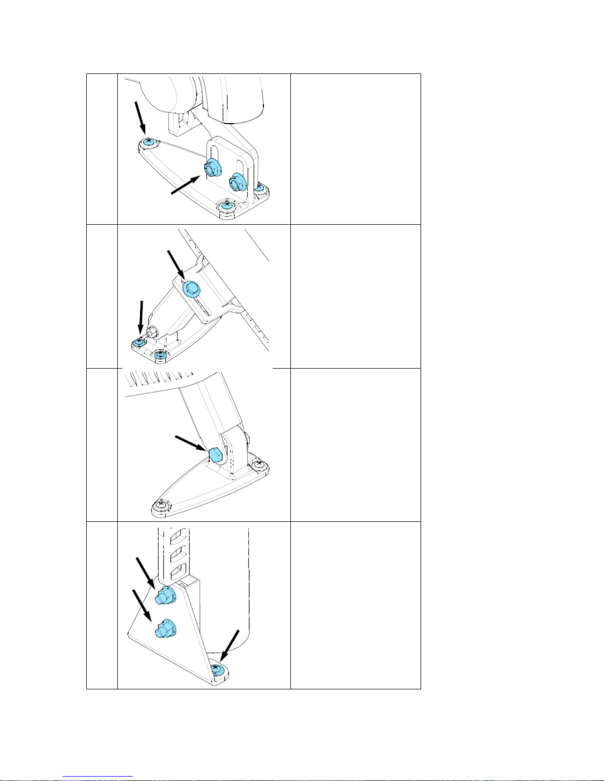
The floor bracket:
1. Insert two hammer-head bolts (1) in the
openings in the rail flange (2).
2. Fix the floor bracket (3) to the rail flange with
the two hammer-head bolts and two
Tensilock nuts (4).
The tread brackets:
1. Prepare the support if necessary.
2. Fit the leg (12) to the foot (10). Do this by
assembling the M10 bolt (13) and locknut
(9).
3. Screw the bolt (7) and washer (11) into the
wedge in the leg (12) with the rail bracket (6)
between them at the right height.
CAUTION
Always fit the nut out of sight on the side
facing the wall. Fit the bolt on the side facing
the stairs.
The landing brackets:
1. Fix the landing bracket (14) to the rail flange
(16) with two Tensilock bolts (15).
Page 7

7
2.2 Connecting the rail sections with a section bush
1. Tighten (loosely) the four socket-head screws
in the section bush so that the four nuts are
trapped in the slot on the inner surface.
2. Fit the section bush in the end of a rail
section and adjust it to the correct position.
3. Lock the section bush by tightening the first
socket-head bolt (do not over-tighten).
4. Slide the other rail section over the section
bush and make sure that the two sections
mate properly.
5. Position a locking pin in the uppermost hole
in the rail section.
6. Push the locking pin using a welding clamp
or adjustable wrench into the rack.
2.3 Installing the feeder cable
1. Pull the two-core feeder cable with a cable
puller through the rail section tube.
2. Pull the feeder cable through the opening in
the flange for the charging contacts. Ensure
that the length through the rail hole L is
approximately 20 cm.
NOTE
A rail section with a parking point will be
fitted with an extra bracket with a feedthrough opening. The two-conductor feeder
cable must also be fed to this.
Page 8
8
2.4 Fitting and installing the charging contacts
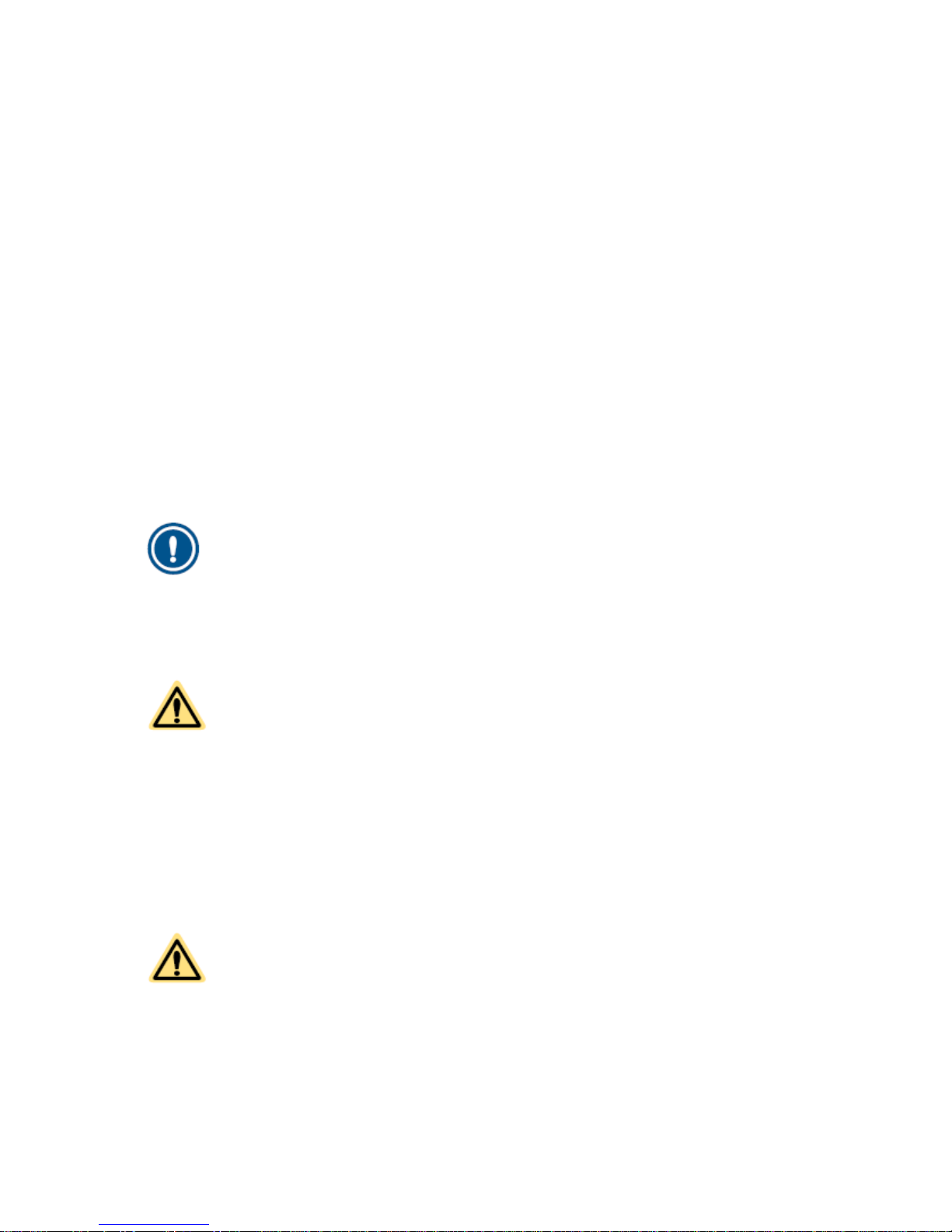
2.4.1 Fixed charging contacts
The positions of the fixed charging contacts are
prepared on the rail at the factory. The charging
contact is installed as follows:
1. Strip approximately 9 cm of the feeder cable.
2. Attach a Faston connector to the cable ends.
3. Feed the cables through the charging
contact.
4. Secure the Faston connector on the lips in
the charging contact.
5. Fit the charging contact to the rail with (2x)
M6x16.
6. Adjust the position of the charging contact so
that it is in line with the drive unit spring
contact. Adjustment is always necessary for
a vertical start.
7. For the polarity of the contacts, please see
section 2.4.3
Page 9
9
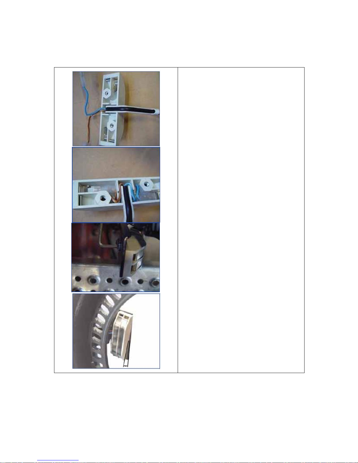
2.4.2 Add-on charging contacts
There are also charging contacts that can be
fitted afterwards by a technician. The bracket for
this charging contact is attached to the rail with
two screws.
Make sure that when you order this charging
contact you also specify the color of the rail.
Only mount the movable charging contact at the
following places:
straight sections of the rail.
vertical bends in the rail.
horizontal bends in the rail.
The bracket cannot be mounted on combined
bends (Spirals). The center of the bracket must
be a minimum of 130 mm from the beginning or
end of a Spiral.
Fit this charging contact as follows:
1. Select a hole in the tooth rack to which the
movable charging contact can be fitted.
2. Drill holes (5 mm) next to this hole in the
tooth rack (23.5 mm apart, 34 mm to
underside of rack) for attachment of the
bracket.
3. Tap these holes with M6 threads.
4. Drill a hole (16 mm) in the rail for the cable
feed-through (15 mm from the tooth rack).
5. Fit the supplied rubber grommet in the hole
through the rail.
6. Fit the bracket to the tooth rack using the two
screws and two spacers.
7. Connect the charging contact and fit the
charging contact on the bracket.
8. Feed the wiring through the grommet and
through the tube and connect the wiring to
the power supply.
9. Adjust the position of the charging contact so
that it is in line with the drive unit spring
contact.
Page 10
10
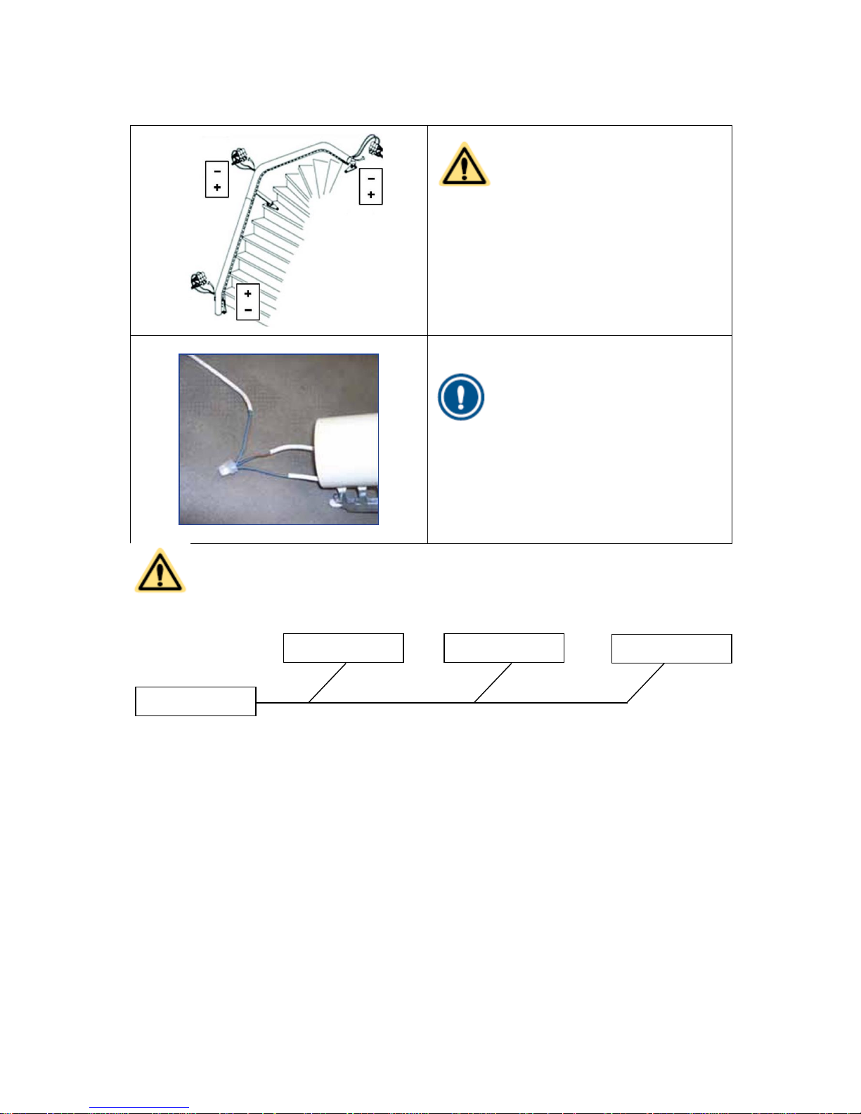
2.4.3 Connection of charging contacts
CAUTION
The connections to the + and - terminals
of the bottom charging contacts must be
reversed as compared to those of the
other charging contacts. This is
necessary to enable the drive unit to
detect that it has reached the bottom of
the stairs and must stop. This is the socalled reset point.
NOTE
For the parallel connection of multiple
charging contacts, the cables can be
connected with splice connector. When
there are several floors, the connection
can best be made at the junction.
CAUTION
Only use original supplied transformer.
Transformer
Charging contact
Charging contact
Charging contact
Page 11

11
2.5 Connecting and mounting the transformer
1. Connect the transformer to the charging contacts closest to a 230Vac wall socket. Use an
extension lead if necessary.
2. Put the transformer plug in the wall socket.
3. Check that the voltage is approximately 33 V and the connection is as indicated in the figures
above.
4. Connect the building wires from the charging contacts to the transformer.
5. Choose a suitable position for the transformer and secure it with four screws and washers.
NOTE
Instead of extending the mains cable you can also extend the building wire and then
fix it out of sight.
Remove the plug from the wall socket.
2.6 Positioning the rail
1. Check the adjustment positions 'X', 'Y' and 'Z'
using the installation drawing. The
adjustment dimensions are measured from
the wall or a tread to the center of the rail’s
pipe.
2. Check the angles and dimensions of the rail
against the installation drawing.
3. Locate the rail in the optimum position.
4. Adjust the legs and brackets such that the
rail is stable on the stairs. Insert one or more
spacers between the legs and the rail if so
required.
2.7 Greasing the rail
1. For greasing, use Super Lube grease and
spread it on the rail with a brush.
Grease the bearing surfaces in the holes.
Grease the support wheel running
surface.
Page 12

12
3 Assembly
CAUTION
Take ESD precautions, such as a mat, strap and shoes. Never touch a circuit board
without taking these precautions.
3.1 Prepare drive unit
1. Place the box with drive unit near the location
where it will be driven onto the rail.
2. Use the top protection cover to put the drive
on the floor.
3. Lift the drive out of the box using the handle
bar on top.
CAUTION
Before powering up the system, make sure it is at room temperature of the
environment where it will be installed.
Page 13

13
Before putting in the fuse, please check that all
connectors are properly connected to the
control board, service board and sensor board.
Remove the front (service) cover and put the 30A
fuse into the drive (right side next to battery) and
switch the drive on by slightly pulling out the red
tab on the back. (A spark is normal when
inserting the fuse)
Check that the blue led on the front is lit. Enter
service mode:
Press the middle (E - enter) button at least 5
seconds, until 0.00 appears in the display.
The number with the dot next to it can be
altered, left button -> “D” - decrement, right
button -> “I” - increment. The digit can be
selected by moving the dot with the Enter
button from left to right.
Enter the password: “245” with use of the
buttons (e.g. press “I”-increment twice for
number 2, repeat for 4 and 5).
Now enter the service mode by pressing the
middle button again for 5 seconds.
You should now be in service mode -2-.
The horizontal lines next to the number 2 are
blinking, indicating that you are in the main
menu.
By pressing the “D” and “I” buttons a menu
can be selected.
For installation, press the “I” button once, so
-3- is displayed.
Now press the “E” button to enter mode -3-.
The horizontal lines next to the number 3 are
now continuous lit.
The lift will go out of the service modes when no command has been given for 5 minutes, it will then
return to normal operation mode.
The password does not have to be re-entered when going through service modes and resetting the lift,
as long as the lift doesn’t go into sleep mode after 2 minutes of no operation (while in normal
operation mode) or has been driven for 5 minutes.
Page 14

14
3.2 Drive onto the rail
1. Position the drive next to the rail, facing front
as how it should be when it is on the rail.
Now lift up one of the bogie half (The one
opposite of the rail) and pull it to the top until
it will not go further.
2. Push the other bogie half onto the rail, (using
your leg if needed) and lifting the drive by its
handle. Now you can drive the main gear by
pressing the button on the front of the handle
in the direction you want to drive. Drive the
lift onto the rail, and make sure the forks on
the bottom of the lift, near the charging
contact are in line with the rack.
3. Once the main gear runs into the rack, check
the forks again, so they are still in line with
the rack. Slowly, one bit at the time drive the
unit further onto the rail, checking that
everything is aligned, until the second bogie
half set it fully onto the rail. Now disconnect
the handlebar from the mainboard and
connect an installation joystick to the 3 pin
connector.
4. Now disconnect the handlebar from the
controlboard and connect an installation
joystick to the 3 pin connector. Use the
adapter cable 1000217
Page 15

15
3.3 Calibration of level sensors
Before the lift can be used, the level sensors should be calibrated to ensure a level and steady ride
quality. This should be done for the main level sensor (CHr) and safety level sensor (SAF).
1. Exit mode -3- by pressing the “D” and “I” buttons at the same time.
2. Select mode -4- by pressing “I” and press “E”.
3. Press the “I” button, “CHr” will be displayed.
4. Press the “E” button, “0” will be shown. With “D” and “I” the chair level can be given an
offset.
5. Put a spirit level on the swivel pedestal, and set it horizontal if necessary.
6. Press and hold “E” to store the value.
7. Press the “E” button again, and press “I” twice, “SAF” will be displayed.
8. Press the “E” button, “0” will be displayed.
9. Press and hold the “E” button to store the safety sensor value. The safety sensor will be
aligned with the main level sensor.
10. Exit mode -4- by pressing the “D” and “I” buttons at the same time
In later releases after r71, the calibration has been simplified where both sensors can be
calibrated simultaneously. This will go as follows:
1. Select mode -4-
2. The display shows the main sensor offset
3. This can be changed by pressing “Ï”and “D”, setting the chair level
4. Press and hold the “E” button to confirm
3.4 Basic installation with rail data
The rail data is programmed onto the lift memory
at the factory. It is also provided on the micro SD
card that is located on the back corner on the
main board. The flashcard also contains the main
software (This may be removed in the future)
CAUTION
Always use: Micro SD minimum 1Gb or Micro SDHC minimum 4Gb class 2
Page 16

16
Use the installation joystick to drive the unit down
the track, use the adapter (1000217) to connect
the joystick to the controlboard. (if you have
installed it from the top side / when it has a
vertical start) until it reaches the charging
contact. (If the unit is installed from the bottom
side, drive the unit past the charging contact,
and drive it back onto the charging contact.)
When the drive contacts touch the reset contact
on the rail, “rSt” is shown in the drive display.
This resets the internal counter and the drive now
knows where it is on the rail.
3.5 Preparing the drive unit for use
1. Remove the four M8 nuts
2. Remove the handle
3. Remove the 3 pin connector from the controlboard
3.6 Fit the chair base
The height of the seat is set as standard in the factory to the middle position. This can be adjusted
according to the customers height. Adjust the chair base height according to section 3.8 if needed.
1. Remove the chair base from the box.
2. Remove the cover under the seat on the chair
base.
3. Lift the seat onto the seat flange.
4. Screw the M8 nuts onto the protruding
threaded ends. Use 20Nm to tighten them.
5. Connect the wire for the User interface.
6. Refit the cap under the chair base.
7. Estimate the size of the user.
8. Adjust the seat position as necessary
(section 3.8 and 3.9).
9. Check the length of the safety belt. Adjust
this if necessary (section 3.10).
Page 17

17
3.7 Installing the manual swivel seat fitting
1. Remove the four threaded ends from the
squeeze unit flange without damaging them.
Set the threaded ends aside; you will need
them later.
2. Remove the two screws. These are no longer
needed and can be discarded.
3. Screw the ball head to the squeeze unit on
the opposite side to the swivel side. Click the
linking rod on the ball head. Using the
locking pins. Grease the ball heads with a bit
of Superlube.
4. Secure the ball head using the spring clip.
5. Insert the link rod under the cover of the
chair base and attach it to the squeeze unit.
6. Secure the chair to the chair base with three
socket-head screws.
7. Grease the ball head with a bit of Superlube.
8. Place the free end of the link rod over the ball
head and lock the swivel.
9. Drive the drive unit back and forth on the rail
and check the adjustment of the anti-squeeze
unit.
10. Adjust the length of the link rod if necessary.
11. Press the (still loose) end of the link rod onto
the ball head.
12. Secure the ball head using the spring clip.
13. Fit the threaded ends into the cover.
14. Fit the chair base.
Page 18

18
3.8 Chair base height adjustment
The height of the chair base can be adjusted for the customer. This is done by choosing one of the
positions. Each position corresponds to a certain height.
The following rule of thumb applies for raising the chair base:
An increase of one position of the seat height is accompanied by setting the footrest one
position lower.
The lowest position of the swivel height is not allowed. It will damage the cables for the swivel
and sensors.
1. Remove the seat from the drive unit:
Remove the cover under the seat.
Remove the four m8 nuts.
Place the seat next to the drive unit.
2. Remove the service cover.
3. Remove the cover over the seat height
adjuster.
4. Adjust the height by moving the seat height
adjuster to a position higher or lower than 3.
Unscrew the four M8 nuts with 13 socket
spanner.
Move the height adjustment bracket frame
to the correct position.
For position 1: turn the height adjustment
180º by holding the sensor board with
cover at an angle in mode 3. This creates
an extra low position. Place the bracket
over these threaded ends and tighten the
nuts on them.
For position 2: unscrew all the nuts, place
the bracket on the right pins, fit the nuts
and tighten them.
For position 4: turn the bracket around
and tighten the nuts again.
CAUTION
The hole in the bracket frame must
align with the height adjuster frame.
5. Refit the height adjuster cover.
6. Refit the service cover.
CAUTION
Ensure that the cables are not
trapped.
Page 19

19
3.9 Height of the footrest
The position of the footrest depends on the height of the chair base. The following rule of thumb
applies for setting the height of the footrest:
An increase of one position of the seat height is accompanied by setting the footrest one
position lower. To move the footrest one position lower, the footrest shaft must also be moved
one position lower and the linkage one position higher.
1. Lay the chair and use a clamp, as necessary,
to stop the chair base from folding up.
2. Adjust the linkage following the rule of thumb
by unscrewing the m6xl6 bolt and sliding the
linkage out. The post is in position 3.
3. Remove the two brackets by unscrewing the
M6x16 bolt and sliding them out of the
frame.
4. Set the correct position of the footrest shaft
higher or lower than position 3, according to
the rule of thumb.
5. Secure the linkage and the brackets again
with an M6x16 bolt.
CAUTION
The
centre
position is marked on the linkage by a rectangle (□) and on the footrest by
an arrow (►).
Page 20

20
3.10 Adjusting the length of the safety belt
1. Remove the cover on the left armrest with a
flat screwdriver.
2. Move the pin to the right hole in the safety
belt.
3. Refit the cover.
3.11 Fixing the rail to the stairs
After making a test ride, the rail position is optimal. The supports can now be fixed definitively.
CAUTION
After
fixing
each bracket check the rail to verify that it has not shifted.
1. Fit the rail system landing brackets with the correct mounting materials to the stairs. Drill holes
if necessary.
2. Fit the rail system tread brackets with the correct mounting materials to the stairs. Drill holes if
necessary.
3. Fit the rail system floor brackets with the correct mounting materials to the stairs. Drill holes if
necessary.
CAUTION
After fixing the rail, check that the drive unit charging assembly does not touch the
rail supports. Loosen the bolt concerned and use a clamp that pushes the rail further
from the rail support. Then re-tighten the bolt.
Page 21

21
3.12 Registering controls
A repeater can extend the range of the call/park transmitters. This should be considered if there are 4
floors or more and the floors contain concrete and/or steel. For installing a repeater, please follow the
next steps:
Place the supplied batteries in the controls where needed and use the supplied adapter for the
repeater. In case of doubt, please check the condition of the batteries with a voltmeter.
Go to mode -9- and select rPt, set this to “rP1” and store the setting pushing and hold the “E”
button until the “PING”. This tells the lift that a repeater is present.
Now open the repeater housing for pairing.
Connect the repeater to the mains, using the adapter.
Select mode -7- and briefly press “E”, a question mark should appear on the display.
Press and hold the small button on the repeater board until the led starts flashing red/green.
‘rPt’ appears in the display of the stairlift.
Press and hold the “E” button until the “PING”, to register the repeater.
To install the User interface, Attendant control and Call & Park units please follow below steps:
Go to mode -7- and press and hold the “E” button, a question mark will now appear “?”.
Register the User interface and Call/Park units as described below.
Pull out the joystick 1 cm from the user interface and press the centre piece to the left (seen
as sitting on the chair). The red LED lights up, hold it until the LED turns green, now press the
joystick to the right side while the LED is still green. Release the joystick when the led starts
flashing red/green. The control unit is now in pairing mode.
When UI (Or C/P, Att) is displayed, press and hold “E” until the “PING”.
Repeat this for the call/park or Attendant controls. When the LED’s on them flash red/green,
“CP0” is displayed. This can be changed by pressing the “I” button to go up -> CP1,
CP2...CP8, Att and then this can be stored by pressing and holding the “E” button until the
“ping” sounds.
Please label the C/P units from 0 (on halt “0”) up, with each C/P.
Page 22

22
3.13 Setting mode -8-, Assign Call & Park
The Call & Park functions have to be assigned, this can be done in mode -8-.
Figure 3-1: Mode -8- display
The RF equipment is now registered and assigned.
The C/P units should have a “Chair” symbol at the left button (Call chair to you) and a park “P” letter
at the right button (Park chair away).
Enter mode -8- the display will give “000”
The middle number (‘000’) can be increased by pressing the “E” button. It is not possible to
decrease the number here. In this case you must keep repeatedly pressing the button until the
numbering starts at '0' again.
Check whether the call and park positions (Call ‘000’, Park ‘000’) are correct for the Call & Park
units just registered. If not, the positions can be changed with the [D] and [I] buttons. Press the [E]
button for at least 2 seconds until the “PING”, to save all the positions that have been entered.
So for example the stair lift in Figure 3-2 has CP0 downstairs and CP1 upstairs. Halfway the staircase
there is a park contact “P1”.
Figure 3-2: C&P assignment
When the CP0 calls the chair, it goes to “H0”. When the CP0 parks the chair, it goes to “P1”.
The first setting in mode 8 should now be 001. The C/P unit upstairs, CP1 wants to call the chair to H2,
and park it at P1, the setting in mode 8 will then be 211.
Page 23

23
3.14 Safe position
The lift is fitted with a maintenance timer. One of the timers tells the user that the joystick emergency
stop should be tested. After 180 hours of (driving) usage, the lift will give a warning to perform the
emergency stop test. This warning consists of:
1. An audible signal.
2. An error code in the display: C71.
3. A flashing red led on the armrest for 1 second.
After 200 hours of usage the lift will halt on the safe position, give F72 and will not travel until the test
is performed. This test consists of removing the joystick from the User interface and re-insert it after 5
seconds. With this, the two switches are tested if they still work correctly and are not stuck. With some
(to be determined in the future) errors, the lift will still travel until it reaches a preset safe halt point.
This is to ensure that the end user does not get stuck on the lift in the middle of the stairs. This safe
halt point can be set in mode -9- and should be a halt point where the user has access to a telephone
(to call service) and is safe for a while. To set this Safe halt point follow the below steps:
Figure 3-3: Safe position in display
Go to mode -9- and press the middle button until: "SP0" will appear (Safe Position).
Select the SP position you want to set by pressing increment and decrement, so this changes to
SP1..SP2…etc.
Press and hold the middle button until the “ping”, the safe point is now stored.
Page 24

24
3.15 Installation without raildata provided
First the parameters and some settings need to be performed before the rail data is build:
Select mode -9-.
Press “E” until “CLr” shows in the display.
Press and hold “E”, this will clear the rail data and parameters, to be sure these are empty
and default. The lift will reset after this, so enter menu -9- again.
In mode -9- set the rail side Left or Right and Automatic or manual swivel.
Exit mode -9- by pressing “I” and “D” simultaneously.
Perform a reset run before proceeding with programming raildata, as described in section 3.4.
Register the RF and user interface devices as described in section 3.12.
3.15.1 Programming rail data in mode -6-:
In mode -6- the following settings can be programmed at any point of the rail:
Speed – “S”
Angle – “A”
Halt – “H”
Park – “P”
Rotate – “r”
Go to mode -6-.
Press the “E” button once, S in now displayed.
Drive the lift with the installation joystick to the center of the reset contact.
Press the “E” button repeatedly until “H--” is displayed.
Halt setting:
Select “H00” with the “I” and “D” buttons.
Press and hold the “E” button until the “PING”.
Set the (S) speed with the “I” and “D” buttons, for this start point (typical 40). The value will
be stored when entering the next setting.
Set the Angle for this start point (A) and the rotation (r) in case of an auto swivel version.
Drive the lift up until another speed, angle, halt or park needs to be entered and do this the
same way as described above.
Do not set a halt and park at the same position.
Page 25

25
Speed settings:
The software will calculate the intermediate speed for each point between two speed settings, also
called interpolation. This means that we only program the speed at certain points on the rail, with a
minimum of the start (H0) and end point (H1).
Figure 3-4: Rail with speed settings
Typical speed settings are:
Vertical stop 40
Horizontal landing 40
Inside curve 60
Outside curve 40
Lower curve 60
Upper curve 40
Straight rail 90
If higher speed settings will be used, the user could experience a rough ride, so it is not recommended.
The speed settings need to done in such a way that the lift is able to accelerate / decelerate quick
enough to reach the speed setting on each entry point. For example; when a speed of 40 is
programmed at H0 and 5 cm later a speed of 80 is entered, this would cause an error. The lift is not
able to accelerate from speed 40 to speed 80 within 5 cm of rail. When the lift then does not reach
speed 80 on the set point, it detects an issue and stops with Error F06.
To calculate the minimum distance between the speed settings the following formula has to be used:
𝐷𝑖𝑠𝑡𝑎𝑛𝑐𝑒 =
S1 − S2
2
≫ =
90 − 40
2
= 25cm
Figure 3-5: Curved railpiece.
Distance in cm. S1, S2 = Speed setting 1,2 ->always highest speed as S1 (the distance is always
positive).
Page 26

26
Angle settings:
As for the speed, the software will calculate the angle at any point by interpolating the two angle
points programmed. For the angle changes there are also some rules in place. When the angle
changes too quickly, the swivel motor cannot keep up and this can cause warning C87.
Figure 3-6: Direction of rotation.
For the angle setting the following formula has to be used:
𝑑𝑖𝑠𝑡𝑎𝑛𝑐𝑒 =
A1 − A2
2
≫
90 − 0
2
= 45cm
Distance in cm.
A1, A2 = Angle A1, A2 -> highest value of the angle first, the angle outcome is always positive.
Halt & Park
There are halt positions, where the user can get on and off the lift and there are park positions, where
the lift can be send empty, to store it away from the walking path (and out of sight). The halt points
are always on a floor.
Here the user has access to: the living room, bedroom, toilet, exit etc.... The park positions can be at
any of these halts, but also on the middle of the stairs, under the stairs, upstairs behind the stairs and
so on. When the park position is the same as a halt position, only a halt position (H) will be
programmed. In case of a park position only, it needs to be programmed as a park (P). This park can
only be reached with the C/P units, not with the UI or attendant control units. The UI will pass these
positions, but will not stop there.
At each halt or park position there must be a charging contact, so the stair lift will charge its batteries
there.
The Halt and Park stations should be sequentially numbered from ‘0’ the lowest point on the rail, up to
the highest halt or park. For example H0, P1, H2 but also P0, H1, H2 is possible.
Figure 3-7: C&P assignment
Page 27

27
Rotation:
A rotation is only possible with an automatic swivel.
A rotation can only been programmed at a halt position. The rotation starts when the stair lift is at a
halt position. This to ensure that the user rotates away from the stairs and can get out of the chair
safely.
3.15.2 Test drive mode -2-:
When all the raildata has been entered, a test ride can be made in mode -2- using the installation
joystick. This should be done with an empty chair as some parts the safety system is still switched off.
When a control unit is controlled, the display shows which unit. Also the battery voltage is shown when
the “E” button is briefly pressed in mode -2-.
3.15.3 Setting the swivel offset in mode -5-:
Mode -5- can be used to set an offset to the swivel position. This is done in the factory and should not
have to alter in the field.
If needed:
Enter mode -5-
With “D” and “I” the swivel offset can be altered
Press and hold the “E” button until the “PING” will store the value.
3.15.4 Functions mode -9-:
For other settings and functions in mode 9, please refer to tab 6, systematic fault finding and tab 2,
system description.
Page 28

28
3.15.5 Create a backup of the programmed rail data and parameters:
Enter mode -9-
Press the “E” button repeatedly until “BU” is displayed.
Press and hold the “E” button for at least 3 seconds, now “L00” will be shown in display.
With the “I” and “D” buttons a memory location on the flashcard can be selected.
Select a memory position 0-99 to store the rail data on the flashcard. Press and hold the “E”
button to store, confirmed with a “ping”.
The factory data will be stored in position 99 on the flashcard
Switch the lift to user mode by executing only one of the 3 options below:
1. Press the “D” and ”I” button simultaneously, to go up one menu level, do this twice to go to
user mode.
2. Press the reset button on the main board.
3. Switch the lift off and on again.
Now make a full test ride on the stair lift in mode -0- (operating mode). Drive up and down while
sitting on the chair, during this ride, the lift will give an C70 in the display, indicating that the test drive
has not been finished yet.
During this test drive no other errors should be seen. If other errors occur, please refer to the
troubleshooting section of Tab 6, Systematic fault finding to find out what is wrong.
Place the top and service cover on the drive, fill out the log book if applicable and make sure the lift
looks in pristine condition.
Page 29

29
4 Releasing the chairlift
4.1 On-site installation test
The on-site installation test is certified by the Notified Body (Liftinstituut) and complies with the
European Harmonized Standard EN 81-40 and the Machinery Directive 2006/42/EC. In order to
comply with EN 81-40, you must test the installation on-site.
WARNING
Perform the on-site installation test after installation of the chairlift.
4.1.1 Static load test
Perform the test with a weight of 125% of the rated load at three points along the rail.
4.1.2 Torque wrench test
Use a torque wrench to check the torque of the load-carrying fasteners:
Screws Ø 6 Torque: 4.5 Nm
Bolts/Nuts M8 Torque: 10 Nm
Bolts/Nuts M10 Torque: 22 Nm
Check all items on the checklist and tick them off.
1
Chair
Nuts, 20 Nm
2
Rail joint
Socket-head screws, 22 Nm
Page 30
30
3
Rail support (floor bracket)
Bolts, 22 Nm
Screws, 4.5 Nm
4
Rail support (tread bracket)
Bolt and nut, 22 Nm
Screws, 4.5 Nm
5
Rail support (tread bracket)
Bolt and nut, 22 Nm
6
Rail support (landing
bracket)
Bolt and nut, 22 Nm
Screws, 4.5 Nm
Page 31

31
4.2 Inspecting the installation and the safety devices
Check all items on the checklist and tick them off.
Drive unit / chair
1
No damage to the paint, the upholstery or the plastic covers.
2
The wiring has been connected correctly and is not pinched.
3
The control buttons operate correctly.
4
The bolts and nuts are tight.
5
The footrest does not touch the steps.
6
The footrest does not touch the wall.
7
The clearance between the seat and the landing floor/ceiling is at least 900 mm from the
centre of the chair.
8
The clearance between the armrest and the wall top/bottom is at least 80 mm.
9
The backrest does not touch the wall.
10
Boarding and alighting heights (as measured from the seat):
Top: ….. / Bottom: …..
Foot rest height:
Top: ….. / Bottom: …..
11
The safety belt is present and adjusted to the correct length.
12
The rotation while the chair is moving works correctly.
13
The armrest control unit is installed on the down-facing side and operates correctly.
14
The blue LED on the service cover lights continuously.
15
The warning tones have been set correctly.
16
The installation number has been entered on the load label.
17
The torque wrench test has been performed (Refer to section 8.1.2).
Rail
1
No damage to the paint.
2
The wiring has been connected correctly and is not pinched.
3
The wiring of the charging contacts has been connected correctly.
4
The bolts and nuts are tight.
5
The end stops (top and/or bottom) have been fitted.
6
The chair moves smoothly over the joints in the rail.
7
The bogie rollers run clear of the rail legs.
8
The spring-loaded charging contact of the drive unit runs clear of the rail legs.
9
The rail has been greased.
10
The torque wrench test has been performed (Refer to section 8.1.2).
Page 32

32
Call-and-park stations
1
The call positions have been correctly set.
2
The park positions have been correctly set.
3
The control buttons operate correctly.
4
All bolts and nuts are tight.
Other
1
If the chairlift is not visible from where the call-and-park stations have been installed,
convex mirrors have been installed.
2
The chairlift is clean and looks tidy.
3
There are no packaging materials or tools in the area around the chairlift.
4
A test ride has been completed.
5
The user has received instructions about the use of the chairlift.
6
The user has read and understood the user manual.
7
The user knows how to switch on and off the chairlift.
8
The user knows how to operate the chairlift using the armrest unit and the call-and-park
stations.
9
The user knows how to use the safety belt.
10
The user knows how to use the safety devices.
11
The user knows how to charge the batteries.
12
The user knows how to maintain the chairlift.
13
The user knows how to rectify simple faults.
14
The user knows how to make a test ride.
15
A backup of the memory card has been made and the memory card has been placed in
the rail end cap.
After the test drive, the lift is fully installed and ready to be used by the customer. Explain the lift to
him/her, hand out the user manual, and relevant telephone numbers to call in case of questions or
issues.
In case of any issues, questions or remarks, please contact:
Ron v/d Munnik or Klaas van Everdingen
+31641598918 +31641533373
rvandenmunnik@tkacc.nl kvaneverdingen@tkacc.nl
Page 33

33
Manufacturer
ThyssenKrupp Accessibility BV
Van Utrechtweg 99, 2921 LN
P.O. Box 754, 2920 CB
Krimpen aan den IJssel
(The Netherlands)
Phone: +31 (0)180 530 900
Fax: +31 (0)180 530 901
E-mail: info@tkacc.nl
lnternet: www.tkacc.nl
 Loading...