

Page 1
I N S T A L L A T I O N I N S T R U C T I O N S
THX-ULTRA II IN-WALL SPEAKERS
PN. 33-3187 10.03
LEFT AND RIGHT SPEAKER PLACEMENT
The ideal mounting height for the LCR speakers is 38 to 42 inches
from the floor to the center of the speaker baffle . This height
corresponds to the height of your ear when you are sitting on a
couch or in a chair.
INTRODUCTION
Thank you for purchasing Sonance Cinema Ultra II speakers. When
properly installed, this product will provide you with years of
entertainment pleasure.
To obtain the full potential of this product, please read all instructions
before starting the installation.
PARTS LIST - Ultra II LCR
Each Sonance Cinema ULTRA II LCR speaker package includes the
following items:
(1) THX ULTRA II LCR in-wall speaker
(1) Paintable grille
(1) Plastic paint plug to protect speaker during painting
(1) Mounting cutout template ( in packaging )
(6) Rotolock towers ( 4 corner and 2 side )
PARTS LIST - Ultra II SUR
Each Sonance Cinema ULTRA II SUR speaker package includes the
following items:
(2) THX ULTRA II SUR in-wall speakers
(2) Paintable grilles
(2) Plastic paint plug to protect speaker during painting
(1) Mounting cutout template ( in packaging )
(12) Rotolock towers ( 8 corner and 4 side )
OPTIONAL ACCESSORIES
Cinema FlexBracket - part number 92023
Plastic template to reserve hole in new construction.
Designed to be used with the RotolockJ
mounting system.
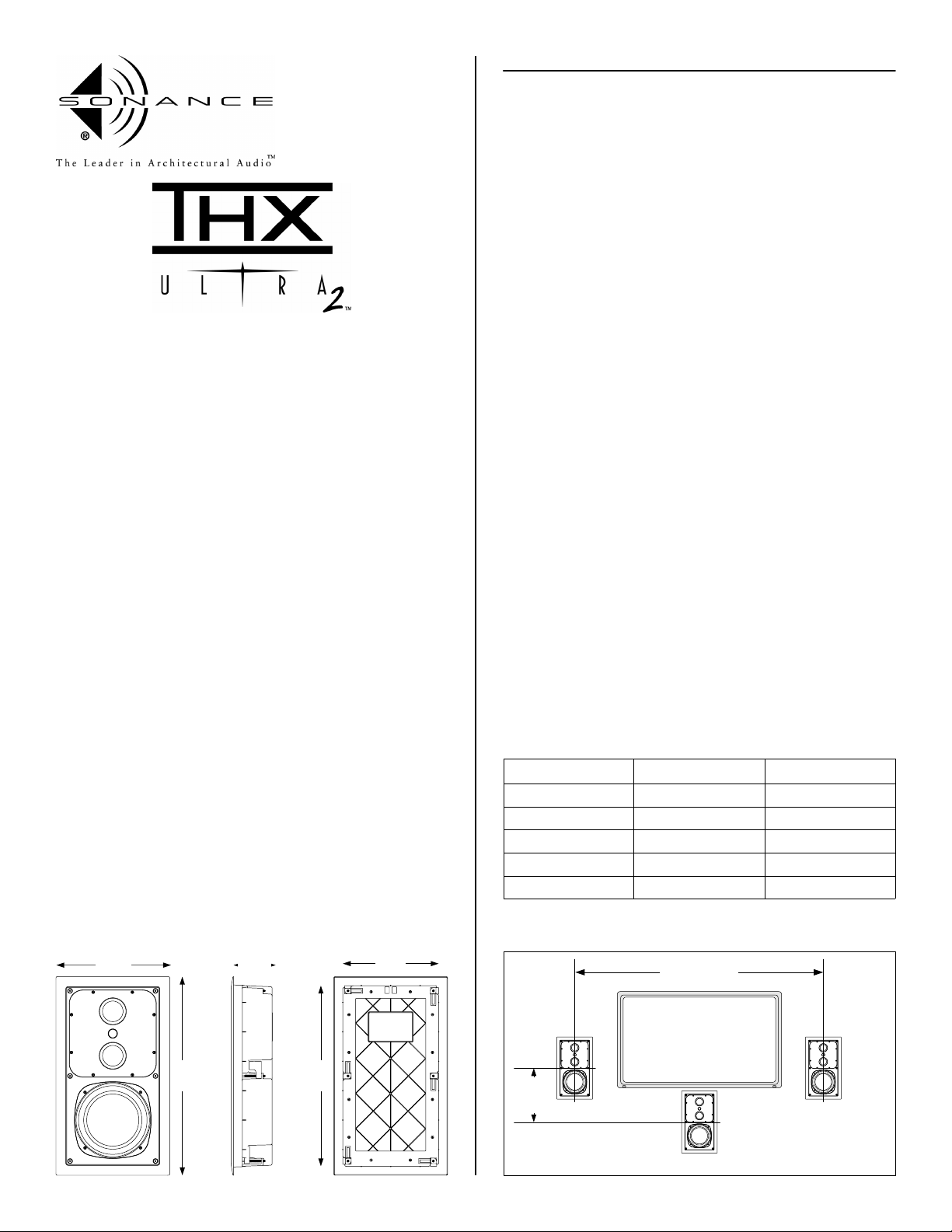
DIMENSIONS - LCR
Use the chart below to determine the placement height of the
speakers. As part of the THX Ultra II approval process the LCR
speakers have very broad vertical dispersion, approximately +/-10
degrees.
The left and right speakers should be separated from 6 to 10 feet
apart center to center. If the speakers are separated too far apart
the sound will seem to come from each front speaker. If the speakers
are placed too close together the sound will seem too congested
around the television.
Note: The Ultra II LCR can be placed horizontally. When
placing the speaker horizontal the midrange / tweeter
plate should be rotated 90 degrees to maintain proper
dispersion.
CENTER CHANNEL SPEAKER PLACEMENT
If possible, locate the center channel in you home theater system the
same height as your left and right speakers (38 to 42 inches from the
floor). If you must place the speaker above or below a television, we
recommend placing the speaker no more than 2 feet above or below
the center of the left and right speakers.
Note: The Sonance Cinema Ultra II LCR speakers are
magnetically shielded to eliminate interference with TV's,
or other electrical devices.
OPTIMAL LCR PLACEMENT HEIGHT
Distance from Speaker Minimum Height Maximum Height
6 feet 27" 53"
8 feet 23" 57"
10 feet 19" 61"
12 feet 15" 65"
14 feet 11" 69"
Height measured to center of speaker from floor
11-9/16"
3-15/16"
20-1/4"
18-3/4"
10-1/4"
2 feet
6 to 10 feet
max.
1
Page 2
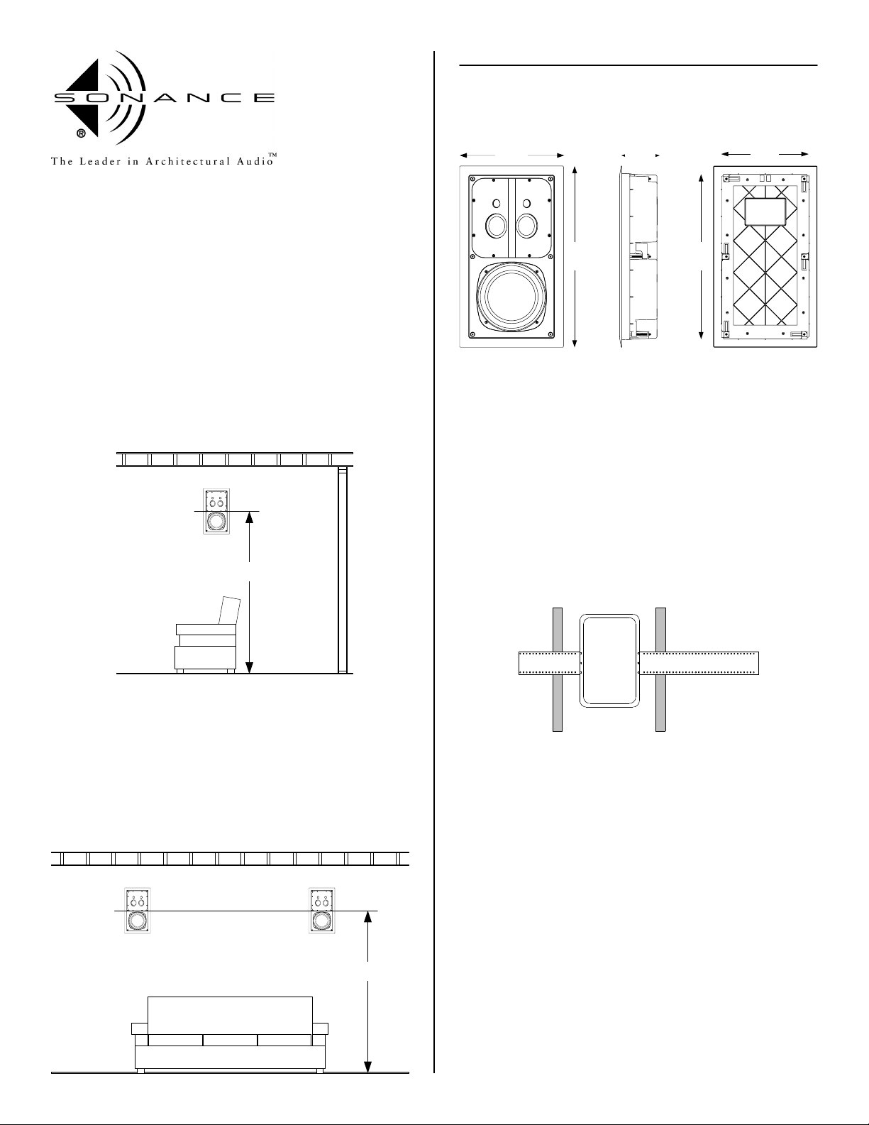
SURROUND SPEAKER PLACEMENT
The ideal mounting height for the Cinema Ultra II SUR speakers is 24
to 36 inches above the height of your ear when you are seated. This
would place the speaker from 60" - 80" from the floor to the center of
the speaker baffle .
The Cinema Ultra II SUR speakers should be placed directly to the left
and right of the listening area, as shown below.
Another option is to mount the surround speakers in the ceiling. When
the speakers are installed in the ceiling the speakers should be placed
to the left and right sides of the listening position and separated 8 to
10 feet apart.
Note: The Cinema Ultra II SUR can be placed horizontally.
When placing the speaker horizontal the midrange /
tweeter plate should be rotated 90 degrees to maintain
proper coverage.
I N S T A L L A T I O N I N S T R U C T I O N S
THX-ULTRA II IN-WALL SPEAKERS
DIMENSIONS - SUR
11-9/16"
20-1/4"
3-15/16"
18-3/4"
10-1/4"
MOUNTING OPTIONS
New Construction
The Cinema Ultra II series speakers feature an integral RotolockJ
mounting system for quick mounting into walls. The Cinema Ultra II
series FlexBracket is only necessary in new construction installations
when reserving a location for the speaker is desired.
60" - 80"
SURROUND BACK SPEAKER PLACEMENT
The back speakers in a 6.1 or 7.1 system should be installed on the
rear wall of the listening room at the same height as the left and right
surround speaker.
If your system will primarily be used for multi-channel music we
recommend the use of one or two additional LCR speakers for the
back surround channel. If you will be playing mostly movies the use of
one or two additional Cinema Ultra II SUR speakers is recommended.
The FlexBracket will serve as a guide for the dry wall installer when
cutting holes for in-wall speakers. The FlexBracket should be nailed or
screwed to the studs so that the hole is in the desired location once
the drywall is installed.
Cinema Ultra II series FlexBracket
Retrofit
With the Rotolock system, the speaker can be installed directly into
existing walls. Once the hole is cut and the cable is run, the speakers
can be installed in a matter of seconds.
Once you have determined the area you would like to locate your
speakers, you will need to do an obstruction survey. Before you cut
the hole for the speaker, be certain no studs, conduit, pipe, heating
duct or air return will interfere with the speaker.
The cutout for the Cinema Ultra II series is 10-1/4 (260mm) x 18-3/4"
(476mm). There must also be 3-15/16" of depth within the wall for the
speaker.
60" - 80"
A cut out template is provided in the packaging of the speaker.
Position the template where the speaker is to be located and pencil an
outline on the wall. If you are unsure about obstructions, drill a small
hole in the center of the cutout and insert a coat hanger into the hole
to feel for possible obstructions. If no obstructions are found,
proceed with cutting the hole using a drywall saw and run the speaker
wires.
2
Page 3

LCR AND SUR - INSTALLATION STEPS
Step 1
Remove the paint plug from the
speaker. Attach the wire from your
amplifier to the binding posts terminals
on the back of the speaker. Double
check the polarity of the speaker wires,
amplifier + to speaker + and amplifier to speaker -. Proper polarity is critical in
home theater installations.
Step 2
Make sure the Roto-Lock clamps are tucked within
the recessed area of the back box, and within the
cutout border. Insert the speaker into the hole in
the wall.
BACK BOX REMOVAL
In some installations the wall depth may not accommodate the
integrated back box. The following steps will allow you to install the
speaker into a non standard wall.
The following steps should also be followed if you are installing the
Cinema Ultra II LCR or SUR speakers into old Cinema 1 or 2 brackets
or acoustic enclosures.
Step 1
Remove the six Rotolock screws from
the speaker. Keep these screws, you
will use them for the Rotolock feet.
Step 2
Remove the six Rotolock clamps. Keep
the Rotolock clamps, you will use these
after the towers are installed.
Note: The maximum clamp thickness is 1-1/4"
(32mm). The minimum clamping thickness is 1/8"
(3.2mm)
Step 3
Tighten the six screws on the front of the baffle.
The Roto-Lock clamps will rotate into position
automatically and begin clamping. When you
notice resistance on the six screws, the speaker
has been clamped successfully. Do not over
tighten the screws.
Note: The flange is designed to flex and conform
to any small imperfections in the wall surface. The
screws should not be tightened so far that the
flange bows out.
Step 4
After the speaker is mounted, the grille
can be installed. Insert about half of
the grille into the groove at the edge of
the speaker. Gently fit the remaining
half of the grill into the speaker.
Note: The torque applied to the
mounting screws can be adjusted for
proper grille fit.
Step 3
Remove the twelve screws that hold
the back box to the frame. Keep the
twelve screws, you will use them to
attach the towers.
Step 4
Remove the back box. The wires
that connect the crossover to the
binding posts will need to be
removed at this point.
Note: If you are installing the
speaker into an old Cinema series
acoustic enclosure or fixed depth
bracket, the speaker is ready to
install at this point. Use the six
Rotolock screws to attach the
speaker to the acoustic enclosure or
fixed depth bracket.
Step 5
Using the twelve screws you
removed from the back box you can
now attach the six Rotolock towers.
Use two screws in each tower.
Note: Included with each speaker
are 4 corner towers and 2 side
towers.
Step 5
The final and most important step in the
installation is to calibrate your system.
Follow your surround processor
instructions for proper calibration
procedures.
Step 6
Install the six Rotolock screws into the toggle
clamps. The speaker is now ready to install.
3
Page 4

WIRE GAUGE AND QUALITY
The total wire resistance should be less than 10% of the speaker
impedance. If using an 4 ohm speaker, your total wire resistance
should be no more than 0.4 ohms.
In simple terms, the extra resistance from the wire will have a very
negative effect on the sound quality of the speaker. The sound can
be less dynamic, definition of bass frequencies can be reduced, and in
extreme cases, the high frequencies can be attenuated. Amplifier
power is also wasted in the wire, reducing the maximum output level
of the system.
Please refer to the following chart when deciding on the appropriate
wire gauge for your installation.
Wire resistance in Ohms vs. length of cable run
Distance in Feet
20 gauge
18 gauge
16 gauge
14 gauge
12 gauge
10 gauge
50' 100' 150' 200' 250' 300'
6.22
5.18
4.14
2.07
1.30
.82
.52
.32
.20
3.11
1.96
1.22
.77
.49
.31
2.61
1.63
1.03
.65
.41
3.26
2.04
1.29
.81
.51
3.91
2.45
1.55
.97
.61
1.04
.65
.41
.26
.16
.10
I N S T A L L A T I O N I N S T R U C T I O N S
THX-ULTRA II IN-WALL SPEAKERS
TECHNICAL ASSISTANCE AND SERVICE
The Technical Assistance Department at Sonance is available at (800)
582-0772 or (949) 492-7777 to answer any questions concerning the
operation and installation of your speakers between the hours of
7:00 AM and 5:00 PM Pacific time, Monday through Friday, except
holidays.
In the event your unit should need repair or service, you may return
the unit to your authorized dealer or use the following guidelines:
1. Be prepared to state the model number and / or serial number,
date of purchase and dealer's name and address when calling.
2. Contact Sonance directly at (800) 582-0772 or (949) 492-7777
or at www.sonance.com
3. If you are returning the product directly to Sonance, call us to
obtain a return authorization number before shipping. YOU MUST
HAVE PRIOR AUTHORIZATION TO RETURN YOUR UNIT.
4. The original packaging must be used. If the original packaging is
unavailable, replacements can be obtained from Sonance for a
small fee.
5. Ship the product via United Parcel Service, Federal Express, or
RPS. Please do not use the U.S. Mail service.
PAINTING THE SPEAKERS AND GRILLES
Speakers and grilles can be painted before installation, which will
eliminate the "paint scar" if the speaker needs to be removed for
service. Speakers may also be painted after installation, but before
the grilles are attached. All speakers come from the factory fitted
with a plastic "paint plug." Use the paint plug to protect the drivers
while the flange is being painted with the wall.
Sonance suggests always painting the grilles separate from the
speaker. The grilles may be lightly sprayed with thin paint (5 parts
thinning agent to 1 part paint), but be careful not to plug the holes.
Too much paint will adversely affect the sound of the speaker.
Once the grilles and flange are painted and dry, remove the paint
plug from the flange and install the grilles.
SPECIFICATIONS
Cinema Ultra II - LCR
Tweeter 1.0" (25mm) Silk dome, shielded magnet
Midr ange Two - 3.0" (76mm) One piece black Aluminum cones with rubber
Woofer 8" (203mm) One piece black Aluminum cone with a rubber surround,
Frequency Response 70Hz - 20kHz +/- 3dB
Impedance 6 ohms n ominal - 4 ohms minimum
Power Handling 5 - 200 Watts
SPL 90 dB
Grille Aluminum
Adjustments Rotating Midrange / tweeter array
Dimensions H x W x D 20-1/4" (514mm) x 11-9/16" (294mm) x 3-15/16" (100mm)
Cutout Dim H x W 18-3/4" (476mm) x 10-1/4 (260mm)
Shipping Weight 18 lbs (8.2 KG) each
surrounds, shielded magnets
shielded magnet
Cinema Ultra II - SUR
Tweeter Two - 1.0" (25mm) Silk domes
Midr ange Two - 3.0" (76m m) One piece black Aluminum cones with a rubber
Woofer 8" (203mm) On e piece black Aluminum cone with a rubber surround
Frequency Response 40Hz - 20kHz +/- 3dB
Impedance 6 ohms n ominal - 4 ohms minimum
Power Handling 5 - 200 Watts
SPL 90 dB
Grille Aluminum
Adjustments Rotating Midrange / tweeter array
Dimensions H x W x D 20-1/4" (514mm) x 11-9/16" (294mm) x 3-15/16" (100mm)
Cutout Dim H x W 18-3/4" (476mm) x 10-1/4 (260mm)
Shipping Weight 29 lbs (13.2 KG) per pair
surround
6. Write the return authorization number on the outside of the box.
7. Ship to:
Attn: Quality Assurance Department
Sonance
212 Avenida Fabricante
San Clemente, CA 92672-7531
8. FREIGHT COLLECT SHIPMENTS WILL BE REFUSED !
Limited Lifetime Warranty
Sonance warrants to the original retail purchaser only that this Sonance product will be free
from defects in materials and workmanship, provided the speaker was purchased from a
Sonance Authorized Dealer after September 1, 2003. Purchases made before that date carry a
limited 5 year warranty.
Defective products must be shipped, together with proof of purchase, prepaid insured to the
Sonance Authorized Dealer from whom they were purchased, or to the Sonance factory at the
address listed on this installation instruction manual. Freight colle ct shipments will be refused.
It is preferable to ship this product in the original shipping container to lesse n the chance of
transit damage. In any case, the risk or loss or damage in transit is to be borne by the
purchaser. If, upon examination at the Factory or Sonance Authorized Dealer, it is determined
that the unit was defective in materials or workmanship at any time during this warranty
period, Sonance or the Sonance Authorized Dealer will, at its option, repair or replace this
product at no additional charge, except as set forth below. If this model is no longer available
and can not be repaired effectively, Sonance, at its sole option may replace the unit with a
current model of equal or greater value. In some cases where a new model is substituted, a
modification to the mounting surface may be required. If mounting surface modification is
required, Sonance assumes no responsibility or liability for such modification. All replaced
parts and product become the property of Sonance. Products replaced or repaired under this
warranty will be returned to the original retail purchaser, within a reasonable time, freight
prepaid.
This Warranty does not include service or parts to repair damage caused by accide nt,
disaster, misuse, abuse, negligence, inadequate packing or shipping procedures, commercial
use, voltage inputs in excess of the rated maximum of the unit, or service , repair or
modification of the product which has not been authorized or approved by Sonance. This
Warranty also excludes normal cosmetic deterioration caused by environmental conditions.
This Warranty will be void if the Serial Number on the product has been removed, tampered
with or defaced. This Warranty is in lieu of all other expressed warranties. If the product is
defective in materials or workmanship as warranted above, the purchaser's sole remedy shall
be repair or replacement as provided above. In no event will Sonance be liable for any
incidental or consequential damages arising out of the use or inability to use the product, even
if Sonance or a Sonance. Authorized Dealer has been advised of the possibility of such
damages, or for any claim by any other party.
Some states do not allow the exclusion or limitation of consequential damages, so the above
limitation and exclusion may not apply. All implied warranties on the product are limited to
the duration of this expressed Warranty. Some states do not allow limitation on the length of
an implied warranty. If the original retail purchaser resides in such a state, this limitation
does not apply.
www.sonance.com
c
2003 Sonance 33-3187 Rotolock is a trademark of Sonance 10.03
THX is a trademark or registered trademark of THX Ltd. All rights reserved
 Loading...