

Page 1
AT2000 • AT2000 • AT2000 • AT20
00 • AT2000 • AT2000• AT2000 •
AT2000 • AT2000 • AT2000 • AT20
00 • AT2000 • AT2000• AT2000 •
AT2000 • AT2000 • AT2000 • AT20
00 • AT2000 • AT2000• AT2000 •
AT2000 • AT2000 • AT2000 • AT20
00 • AT2000 • AT2000• AT2000 •
AT2000 • AT2000 • AT2000 • AT20
00 • AT2000 • AT2000• AT2000 •
AT2000 • AT2000 • AT2000 • AT20
00 • AT2000 • AT2000• AT2000 •
AT2000 • AT2000 • AT2000 • AT20
00 • AT2000 • AT2000• AT2000 •
AT2000 • AT2000 • AT2000 • AT20
00 • AT2000 • AT2000• AT2000 •
AT2000 • AT2000 • AT2000 • AT20
00 • AT2000 • AT2000• AT2000 •
AT2000 • AT2000 • AT2000 • AT20
AT2000
TM
Assembly
and Operators
Manual
9 Row 30
00 • AT2000 • AT2000• AT2000 •
AT2000 • AT2000 • AT2000 • AT20
00 • AT2000 • AT2000• AT2000 •
AT2000 • AT2000 • AT2000 • AT20
00 • AT2000 • AT2000• AT2000 •
AT2000 • AT2000 • AT2000 • AT20
00 • AT2000 • AT2000• AT2000 •
AT2000 • AT2000 • AT2000 • AT20
00 • AT2000 • AT2000• AT2000 •
AT2000 • AT2000 • AT2000 • AT20
00 • AT2000 • AT2000• AT2000 •
AT2000 • AT2000 • AT2000 • AT20
00 • AT2000 • AT2000• AT2000 •
AT2000 • AT2000 • AT2000 • AT20
5 Row 30
Short Frame
00 • AT2000 • AT2000• AT2000 •
AT2000 • AT2000 • AT2000 • AT20
00 • AT2000 • AT2000• AT2000 •
AT2000 • AT2000 • AT2000 • AT20
Manual Number
0602001
Rev. 6-14-16
All Terrain
Liquid Fertilizer
Injection Toolbar
$20.00 Net.
Page 2

Thurston Manufacturing Company • 1708 H Ave • Box 218 • Thurston, Nebraska, 68062-0218
Phone: 402-385-3041 • Fax: 402-385-3043 • E-mail: box218@thurstonmfgco.com
Design specications and features as described are subject to change without notice. BLU-JET is a registered trademark of Thurston Manufacturing Company, Thurston NE.
/BLU-JET
@BLU-JET01
/SIronWorks
@SIronWorks
Page 3

AT2000
Introduction.................................................................................................................................................. 2
AT2000
Delivery......................................................................................................................................................... 4
To The Owner............................................................................................................................................... 5
Warranty....................................................................................................................................................... 6
Safety............................................................................................................................................................ 7
Operating Instructions................................................................................................................................ 11
Pump Setting................................................................................................................................................. 16
High Pressure Injection System Pump Calibrating Work Sheet.................................................................... 17
Orice Installation.......................................................................................................................................... 20
Rate Charts................................................................................................................................................... 22
Row Spacing................................................................................................................................................. 29
Parts
AT2000.......................................................................................................................................................... 36
Shipping Assembly (32000000)..................................................................................................................... 37
9R30 (76 CM) (32000930)............................................................................................................................. 38
Main Frame (32000001)................................................................................................................................ 42
Adjustable Wheel/Axle (32000002)............................................................................................................... 46
Hub and Spindle Assembly (AAM2891)......................................................................................................... 47
Standard Tool Bar (32000004)....................................................................................................................... 48
Hydraulic Package (PKG00246).................................................................................................................... 49
Gauge Wheel Set (33000112)....................................................................................................................... 50
Extension Brackets (AAM4873) & (AAM4876).............................................................................................. 52
Jack Parts (AM3705)..................................................................................................................................... 53
Flatback (AAM2821) and Flatback Extension (AAM4875)............................................................................ 54
Super 1200 Coulter and Shank Parts............................................................................................................ 55
Pump Drive (32000009)................................................................................................................................. 56
Single Piston Pump NGP-7055 (CP2568)..................................................................................................... 57
Bottom Fill Plumbing Kit (32000005)............................................................................................................. 58
Jet Stream Liquid Assembly (AAM3353)....................................................................................................... 60
Manifold Assembly 3/4” (1,9 cm) (32000010)................................................................................................ 62
Lighting Kit (41000044).................................................................................................................................. 66
Assembly
Shipping Assembly......................................................................................................................................... 68
Cylinder Depth Collars................................................................................................................................... 69
Transport Chain Kit AAM2422........................................................................................................................ 70
Hitch and Utility Plate..................................................................................................................................... 71
Manual Holder................................................................................................................................................ 72
Hose End Holder AAM2398........................................................................................................................... 73
Extension Wings............................................................................................................................................ 74
Gauge Wheels............................................................................................................................................... 75
Hose Holders................................................................................................................................................. 76
Coulter Assembly........................................................................................................................................... 77
Flatback and Flatback Extension................................................................................................................... 78
Coulter Mounting............................................................................................................................................ 79
Liquid Injection............................................................................................................................................... 80
Hose Support Clamps.................................................................................................................................... 84
Manifold Assembly.......................................................................................................................................... 85
Pump Drive..................................................................................................................................................... 88
Chain Tensioner............................................................................................................................................. 90
Pump Mounting.............................................................................................................................................. 91
Pump Drive Chain.......................................................................................................................................... 92
Pump Drive Wheel......................................................................................................................................... 93
Pump Fittings................................................................................................................................................. 94
Lighting Kit..................................................................................................................................................... 96
SMV (Slow Moving Vehicle).......................................................................................................................... 99
Safety Tank.................................................................................................................................................... 100
Decals............................................................................................................................................................ 101
Tie-rod Cylinder Disassembly - Assembly Procedure.................................................................................... 103
Hydraulic Cylinders And Parts....................................................................................................................... 104
Specications................................................................................................................................................. 105
Torque Specications..................................................................................................................................... 106
Storage........................................................................................................................................................... 107
Axle Adjustments............................................................................................................................................ 108
Row Spacing Short Toolbar............................................................................................................................ 113
Shipping Assembly Short Toolbar (32000006)............................................................................................... 115
Short Toolbar (32000003).............................................................................................................................. 116
Task Procedures Illustrations
Table of Contents
Manual Number 0602001
6-14-16
1
Page 4
Introduction
AT2000
Task Procedures Illustrations
Welcome to Thurston Manufacturing Company. Our goal is to provide
quality products and services to our customers. The company’s BLU-JET
products have a reputation for quality, excellence in design and proven
durability. Energetic, resourceful and continuous improvement goals in
Environmental, Safety, Quality, Production and Engineering keep our
rm at the cutting edge of technology.
We hope your BLU-JET equipment will give you years of service.
Read this manual carefully. It will instruct you on how to operate and
service your machine safely and correctly. Failure to do so could result
in personal injury and, or equipment damage.
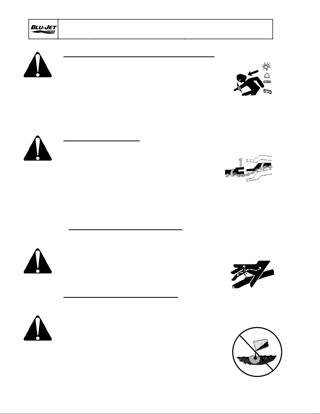
SAFETY INFORMATION
Indicates an imminently hazardous situation that, if
not avoided, will result in death or serious injury.
The sign will have the color combination of red and
Indicates a potentially hazardous situation that, if
not avoided, could result in death or serious injury.
The sign will have the color combination of
and
not avoided, may result in minor or moderate injury.
The sign will have the color combination of
and
DANGER
white.
WARNING
orange
black.
Indicates a potentially hazardous situation that, if
CAUTION
yellow
black.
NOTE: Indicates a special point of information.
Carefully read and follow all safety signs. Reinstall safety signs that
are damaged or missing.
Right-hand and left-hand sides of the implement are determined by
facing in the direction the implement will travel when going forward.
2
Page 5
Introduction
AT2000
Task Procedures Illustrations
General Information:
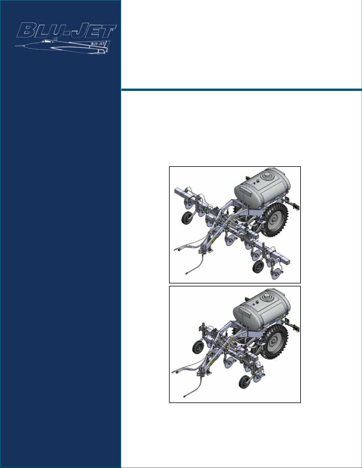
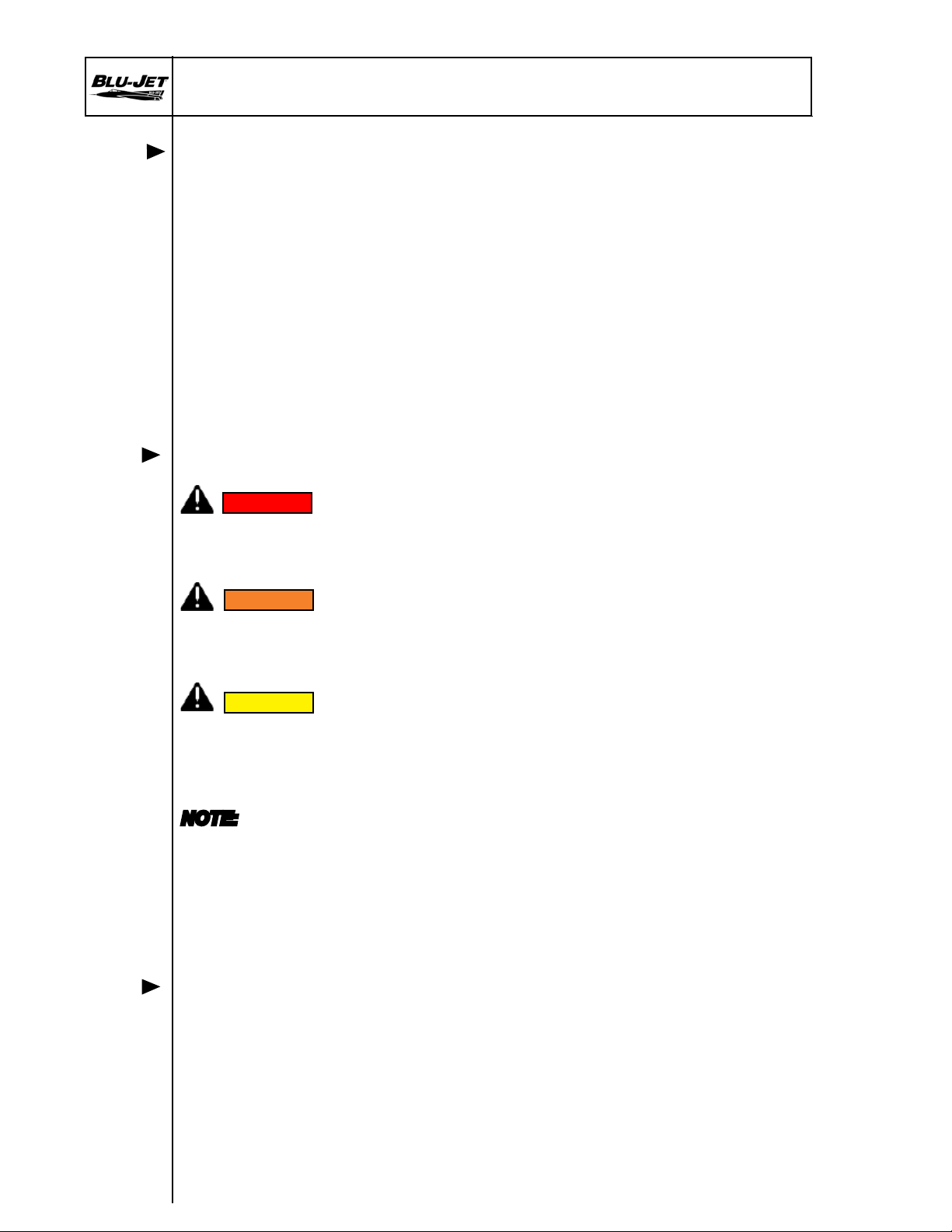
The BLU-JET AT2000 applicator features a 7” x 7” (17.8 cm x 17.8 cm), narrow
folding toolbar. High otation tires reduce the risk of deep compaction within
the soil prole. The 525 gallon (1987 liter) elliptical tank provides the capacity needed
to run longer between lls. The AT2000 is designed for BLU-JET’s JetStream
coulter injection or coulter knife injection.
Warranty is provided for customers who operate and maintain their equipment
as described in this manual. Warranty registration is accomplished by
the dealer completing and forwarding the WARRANTY REGISTRATION
FORM to Thurston Manufacturing Company. It is in your best interest to
insure that this has been done.
For your convenience we have three easy ways to register your warranty.
• Fax completed warranty registration form. Fax: 1.402.385.3043
• Register on-line in warranty page at www.BLU-JET.com.
• Complete and return registration form-by mail.
Thurston Manufacturing Company
1708 H Avenue. P.O. Box 218
Thurston, NE 68062, USA
Thurston Manufacturing Company Warranty does not cover the following:
1) Cleaning, transporting, mailing and service call charges.
2) Depreciation or damage caused by normal wear, accidents,
improper protection or improper use.
See complete Warranty for details.
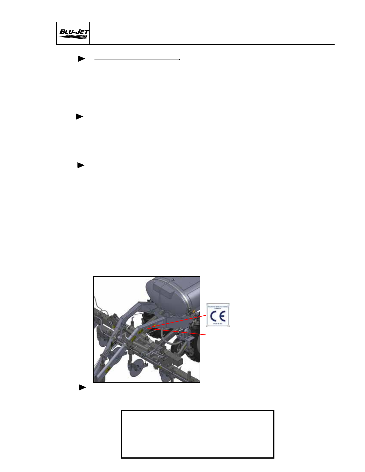
The Serial Number
is located from the
rear of the tool bar
on the left-hand
side of the tongue.
Record your implement model and serial number in the space provided be-
low. Your dealer needs this information to give you prompt, efcient service
when you order parts.
MODEL NO.__________________________
SERIAL NO.__________________________
DATE PURCHASED___________________
3
Page 6

Dealer Checklist
AT2000
Task Procedures Illustrations
To The Dealer:
Inspect the implement thoroughly after assembly to be certain it is
functioning properly before delivering it to the customer. The following
checklist is a reminder of points to cover. Check off each item as it is
found satisfactory or after proper adjustment is made.
PRE-DELIVERY CHECKLIST
1. All hardware properly tightened
2. Lubrication of grease ttings
3. All decals properly located and readable
4. Other adjustments for machine level height, etc.
5. Overall condition (touch up any scratches, clean and
polish)
6. Operator’s manual
DATE SET UP_______________________________
SIGNATURE________________________________
DELIVERY
Review the operator’s manual with the customer. Explain
the following:
1. Safe operation and service
2. Correct machine installation and operation
3. Daily and periodic lubrication and maintenance
4 Daily and periodic inspections
5. Troubleshooting
6. Storing machine
7. Thurston Manufacturing Company parts and service
8. Have the customer write the machine model and serial
number in space provided in manual introduction.
9. Give customer the operator’s manual and encourage
the customer to read the manual carefully.
10. Completion and mailing of warranty registration
form.
DATE DELIVERED__________________________
SIGNATURE_______________________________
MODEL NO.________________________________
SERIAL NO.________________________________
4
Page 7

To The Owner
AT2000
Task Procedures Illustrations
Thank you for your recent purchase of a new BLU-JET
implement. The primary objective of Thurston Manufacturing
Company is to build and provide you with a quality product.
However, in the event that a problem does occur, it is
imperative that your warranty registration is on le in order to
accurately respond to your specic service circumstances.
For your convenience we have four easy ways to register
your warranty:
• Fax completed warranty registration form.
Fax: 1.402.385.3043
• Register on-line in warranty page at:
www.BLU-JET.com
• Complete and return registration form-by mail.
Thurston Manufacturing Company
1708 H Avenue. P.O. Box 218
Thurston, NE 68062, USA
This manual has been prepared to assist you in the assembly
of your new machine and contains information pertaining to
safety, operation and all of its parts. Our personnel in sales
and service are always available to assist you when questions
arise concerning the assembly or operation of your tool bar.
When ordering parts, please refer to part numbers and
descriptions as listed throughout this book. All parts and
whole goods will be shipped FOB Thurston, Nebraska or FOB
your regional distributor. Always check merchandise
immediately upon receipt for damage or shortage. Note any
discrepancy on carrier’s bill of lading and notify Sender within
10 days. Returned goods will be subject to a 15% restocking
charge. Thurston Manufacturing Company reserves the right
to make improvements and modications on equipment
without obligation to change previously built equipment. All
prices are subject to change without notice.
5
Page 8

Limited Warranty
AT2000
Task Procedures Illustrations
Thurston Manufacturing Company warrants each new BLU-JET machine primary
framework to be free from defects in material and workmanship for a period of ve (5)
years, normal wear of wearing parts excepted. Thurston Manufacturing Company further
warrants each new BLU-JET product to be free from defects in material and workmanship,
normal wear of wearing parts excepted, for a period of one (1) year. All accessories purchased and resold by Thurston Manufacturing Company will be warranted according to
their respective manufacturer. Tires on BLU-JET equipment are warranted through their
respective tire manufacturers and their network of dealers in your local area.
Warranty begins from date of delivery to the original purchaser and applies to all
new BLU-JET products that have not been altered and are being used for the intended purpose.
Negligence, abuse or modication of equipment manufactured by or purchased and resold
by Thurston Manufacturing Company will void this warranty.
The obligation of Thurston Manufacturing Company to honor this warranty is limited
to the repair or replacement of defective merchandise, to the original purchaser, subject to
inspection of equipment in question by an authorized Thurston Manufacturing Company
sales or service technician. In the USA, freight of warranty replacement parts including
main frame centers and wings will be prepaid for a period of one (1) Year by Thurston Manufacturing
Company. Shipments of repaired or replaced parts including main frame centers and wings
after one year will be paid by the customer.
Return of defective goods must be made within thirty (30) days of failure to Thurston
Manufacturing Company, Thurston, Nebraska USA or to the nearest authorized BLU-JET
Distributor or Rep Sales and service outlet.
Thurston Manufacturing Company will not be held responsible for any repair charges
made by customers without prior written consent and prior equipment inspection by an
authorized Thurston Manufacturing Company sales or service technician.
This warranty shall not be interpreted to render liability for injury or damages of
any kind, direct, consequential or contingent to person or property. This warranty does not
extend to loss of crops, economic and/or commercial loss, loss because of delay in crop
production or any expense incurred for labor, supplies, substitute machinery, rental or for
any other reason. This warranty is subject to any existing condition of supply, which may
directly affect Thurston Manufacturing Company’s ability to obtain materials of manufacture
and delivery of replacement parts.
Thurston Manufacturing Company reserves the right to make improvements in
design and changes in specications at any time without incurring any obligation to owners
of units previously sold.
No one is authorized to alter, modify or enlarge this warranty nor its exclusions,
limitations and reservations. Thurston Manufacturing Company makes no representations or warranties, expressed or implied (including implied warranties of merchant-
ability and tness), except for those set forth in Thurston Manufacturing Company’s
current applicable published warranty policies and procedures.
Layton W. Jensen, President/CEO 022398\mgmt
6
Page 9
Safety
AT2000
Task Procedures Illustrations
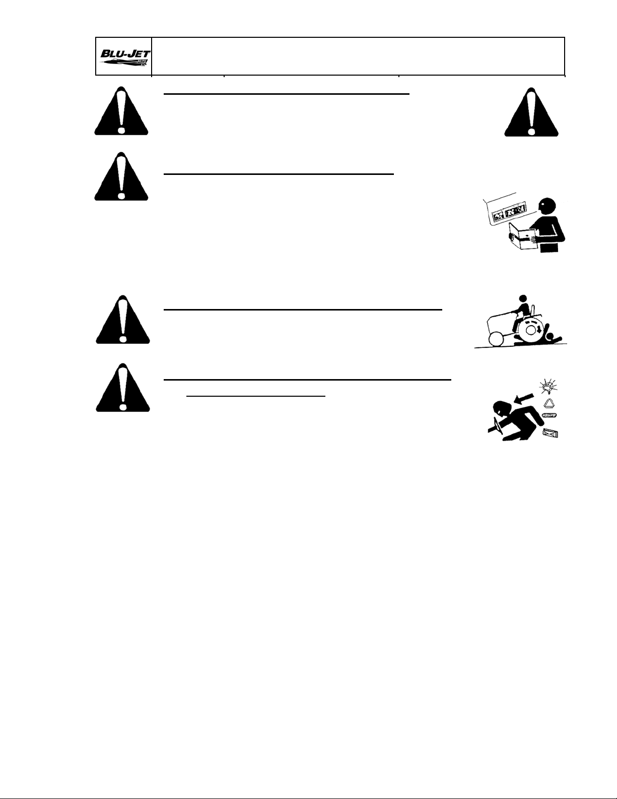
RECOGNIZE SAFETY INFORMATION
• This is the safety-alert symbol. When you see his symbol
on your machine or in this manual, be alert to the
potential for personal injury. Follow recommended
precautions and safe operating practices.
FOLLOW SAFETY INSTRUCTIONS
• Carefully read all safety messages in this manual and
on your machine safety signs. Keep safety signs in good
condition. Replace missing or damaged safety sign.
• Learn how to operate the machine and how to use
controls properly.
• Do not let anyone operate without instruction.
• Keep your machine in proper working condition.
• Unauthorized modication to the machine may
impair the function and, or safety and affect machine life.
PROTECT CHILDREN AND BYSTANDERS
• Before you back, LOOK CAREFULLY behind for
children.
• Clear area of children, pets and bystanders.
HIGHWAY AND TRANSPORT OPERATIONS
Adopt safe driving practices:
• Keep the brake pedals latched together at all times.
NEVER USE INDEPENDENT BRAKING WITH MACHINE
IN TOW AS LOSS OF CONTROL AND/OR UPSET OF
UNIT CAN RESULT.
• Always drive at a safe speed relative to local
conditions and ensure that your speed is low enough
for a emergency stop to be safe and secure. Keep
speed to a minimum.
• Reduce speed prior to turns to avoid the risk of
overturning.
• Avoid sudden uphill turns on steep slopes.
• Always keep the tractor or towing vehicle in
gear to provide engine braking when going downhill.
Do not coast.
• Do not drink and drive.
• Comply with state and local laws governing highway
safety and movement of farm machinery on public roads.
• Use approved accessory lighting and necessary
warning devices to protect operators of other vehicles
on the highway during daylight and nighttime transport.
• The use of ashing amber lights is acceptable in most
localities. However, some localities prohibit their use.
Local laws should be checked for all highway lighting
and marking requirements.
• When driving the tractor and equipment on the road
or highway under (20 m.p.h. max.) (40 k.p.h. max.) at night
or during the day, use ashing amber warning lights
and a Slow Moving Vehicle (SMV) identication emblem.
7
Page 10
Safety
AT2000
Task Procedures Illustrations
HIGHWAY AND TRANSPORT OPERATIONS
• Plan your route to avoid heavy trafc.
• Be a safe and courteous driver. Always yield to oncoming
trafc in all situations, including narrow bridges,
intersection, etc.
• Be observant of bridge loading ratings. Do not cross
bridges rated lower than the gross weight at which you
are operating.
• Always operate equipment in a position to provide
maximum visibility at all times. Makes allowances for
increased length and weight of the equipment when
making turns, stopping the unit, etc.
TRANSPORT SAFETY
• A safety chain will help control drawn equipment
should it accidentally separate from the drawbar.
• Attach the chain to the tractor drawbar support or
other anchor location. Provide only enough slack in
the chain to permit turning.
• Use hydraulic cylinder transport lockup during road
transportation.
• Maximum road speed is 20 m.p.h. (32 k.p.h) with an empty tank.
Tank Fill Maximum Maximum
525 Gallons Highway Application Speed
2,000 Liters 20 m.p.h. 10 m.p.h.
32 k.p.h. 16 k.p.h.
AVOID HIGH PRESSURE FLUIDS
• Escaping uid under pressure can penetrate the skin
causing serious injury.
• Avoid the hazard by relieving pressure before
disconnecting hydraulic or other lines. Tighten
all connections before applying pressure.
• Search for leaks with a piece of cardboard.
• Protect hands and body from high pressure uids.
• If an accident occurs, see a doctor immediately.
DISPOSE OF FLUIDS PROPERLY
• Improperly disposing of uids can harm the
environment and ecology. Before draining any
uids, contact your local environmental agency
for the proper waste disposal methods.
• Use proper container when draining uids. Do
not use food or beverage containers that may
mislead someone into drinking from them.
• DO NOT pour oil into the ground, down a drain, or
into a stream, pond, or lake. Observe relevant
environmental protection regulations when disposing
of oil and other harmful waste.
8
Page 11
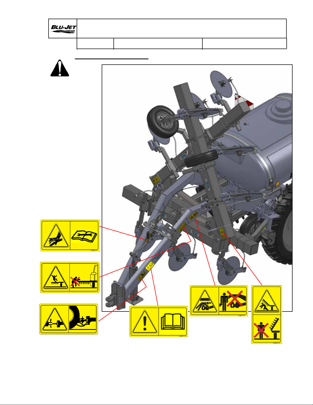
Safety Decals
Falling From Equipment Hazard Decal, AP2564 9-1-12
Actual Size 168 mm W x 88 mm H
Safety Sign Specied Color: Yellow 5.0Y8.0/12
Red 7.5R4.0/14
AP2568 10-12-12
Safety Chain Decal, AP2568 10-12-12
Actual Size 3.46 “ W x 6.61” H
Safety Sign Specied Color: Yellow 5.0Y8.0/12
AT2000
Task Procedures Illustrations
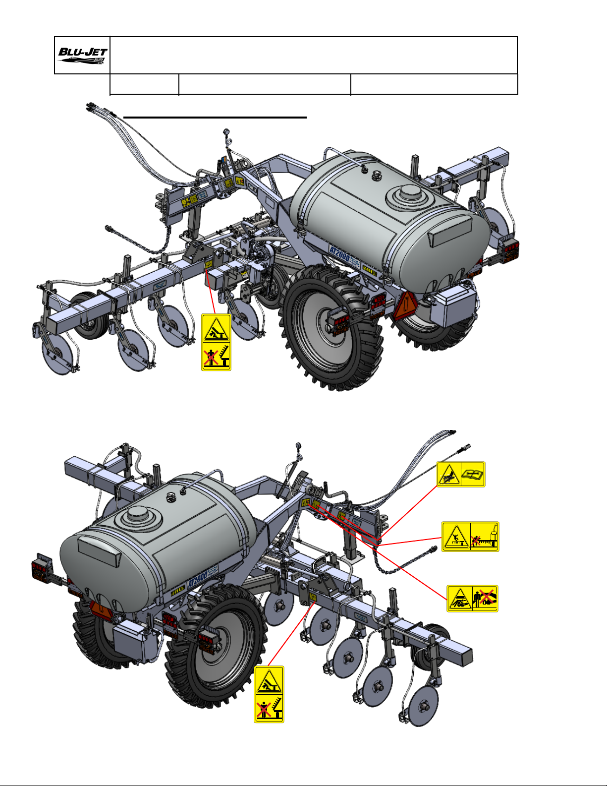
Observe Safety Signs
AP2564: FALLING HAZARD DO NOT CLIMB ON MACHINE
AP2565: HIGH PRESSURE FLUID HAZARD
AP2566: FALLING WING HAZARD
AP2567: READ OPERATORS MANUAL
AP2568: SAFETY CHAIN
AP2569: CRUSHING HAZARD
AP2565
AP2564
AP2568
AP2564 9-1-12
AP2569
AP2567
AP2566
9
Page 12
Safety Decals
AP2564 9-1-12
Crushing Hazard, AP2569 12-12-12
Actual Size 3.465 “ W x 6.614” H
Color: ANSI Yellow, Black. With Clear Coat
FB5000 White Vinyl Material
AP2569 12-12
AT2000
Task Procedures Illustrations
Observe Safety Signs
AP2566 9-1-12
AP2566
AP2564: FALLING HAZARD DO NOT CLIMB ON MACHINE
AP2565: HIGH PRESSURE FLUID HAZARD
AP2566: FALLING WING HAZARD
AP2567: READ OPERATORS MANUAL
AP2568: SAFETY CHAIN
AP2569: CRUSHING HAZARD
AP2565 9-1-12
AP2565
AP2564
AP2569
AP2566 9-1-12
AP2566
10
Page 13
Operating Instructions
AT2000
Task Procedures Illustrations
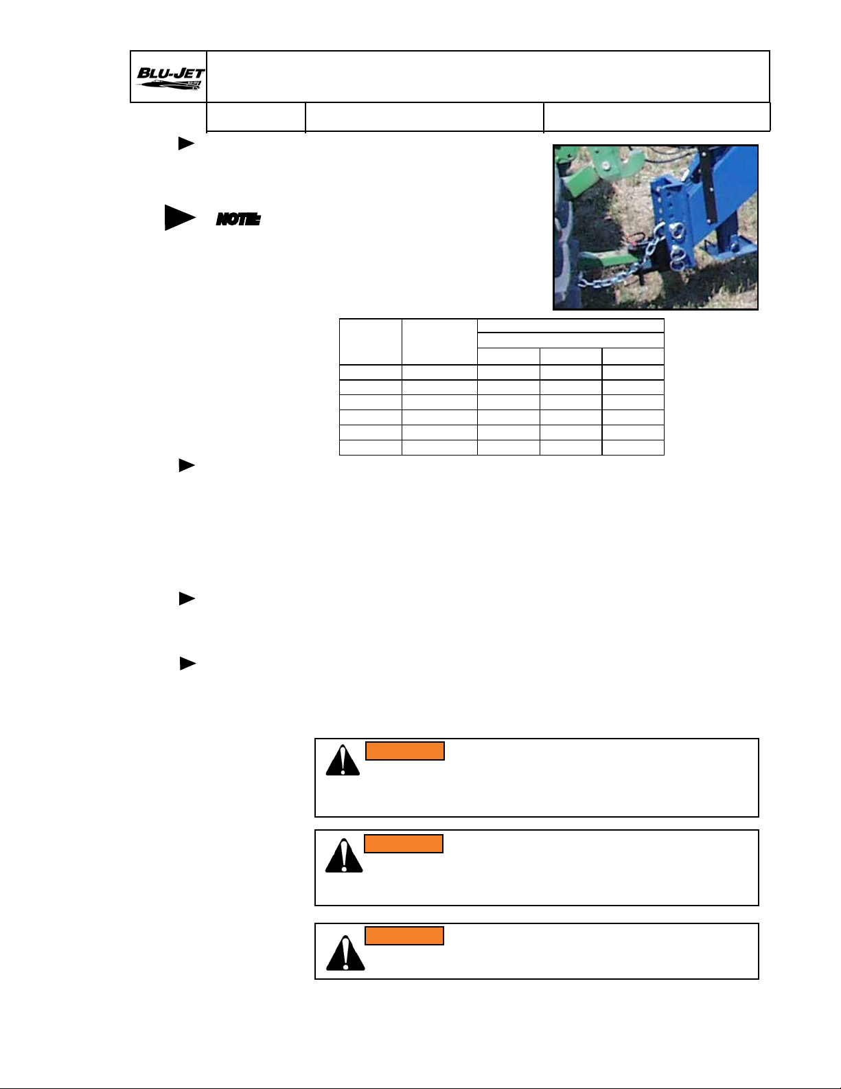
Hitch
NOTE:
Implement
hitch weights
are designed
to match
tractor size
ranges.
Check the
following
chart to
conrm your
particular
implement
specication.
Tractor to
tool bar
connection
1. The tractor must be equipped
with a drawbar and a drawbar
safety chain clevis. For
rigid frame tractors equipped
with swinging drawbar, the
drawbar must be located in a
xed position in the center of
the tractor. Refer to your
tractor operators manual for
drawbar adjustment and
drawbar operating instructions.
Maximum Vertical Static Load (lbs)
Drawbar Position
Category PTO Power (HP)
0 ≤ 38 1,574 1,124 787
1 ≤ 64 2,698 1,798 1,349
2 ≤ 154 4,946 3,372 2,473
3 ≤ 248 6,070 4,046 2,922
4 ≤ 402 7,418 4,946 3,597
5 ≤ 671 10,116 6,744 N/A
Short Regular Extended
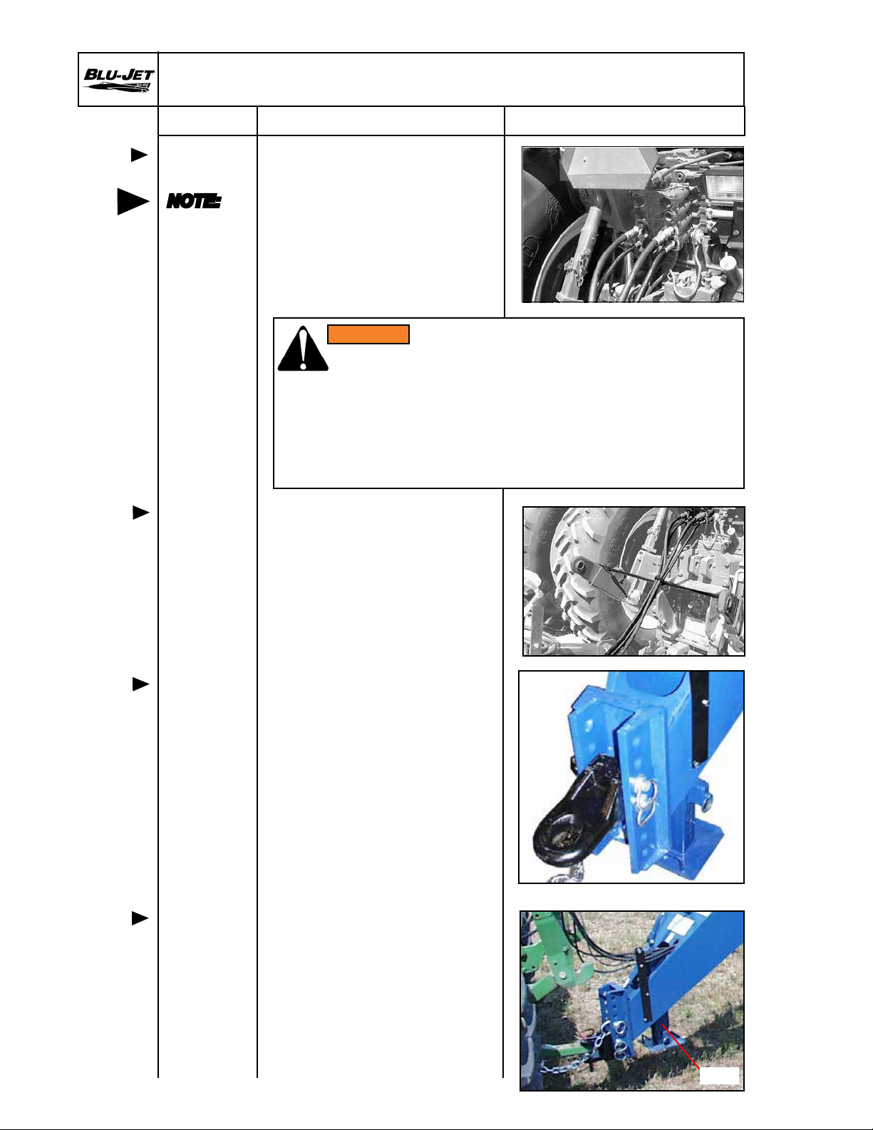
2. Before connecting the tool bar to the tractor drawbar, raise the
tractor three point hitch (if equipped) to prevent interference
between the implement and the tractor.
Connect the tool bar to tractor drawbar ONLY. DO NOT connect
the tool bar to any other part of the tractor. Connect the tool bar
clevis to the tractor drawbar with hitch pin. Install the safety
chain through the tractor drawbar support bracket.
Safety
hitch pin
Safety
chain
3. Always use a safety hitch pin of the correct diameter. Make sure
that the hitch pin is locked in place with a safety type lock pin or
other locking device.
4. Always use a safety chain between the toolbar and the tractor.
Install the chain to the tractor drawbar support bracket. Support
the center of the chain with a clevis installed to the tractor
drawbar.
WARNING: In case the tractor hitch pin is lost during transporting.
WARNING
The safety chain must be attached between the implement and
tractor to prevent separated implement from running freely and
causing damage or injury.
WARNING: Do not move articulated tractor steering wheel
WARNING
until everyone is clear of the equipment. Moving the steering
wheel can swing or move attached equipment which could
cause serious personal injury.
WARNING: Tractor drawbar must be in a xed position before
WARNING
transporting implement. Implement will sway or slam against
tractor resulting in equipment damage or injury to personnel.
11
Page 14
Operating Instructions
AT2000
Task Procedures Illustrations
Remote
hydraulic
NOTE:
Always
connect the
hoses so
the toolbar
raises when
the tractor
remote
control
lever is
moved
rearward
and lowers
when the
lever is
moved
forward.
Remote
hydraulic
5. Connect the tool bar hydraulic
hoses to the tractor remote
couplers. The 3/8” (9,5 cm)
hoses supply oil to the tool
bar lift cylinders. The 1/4”
(6 mm) hoses supply oil to
the wing fold cylinders.
6. It may be necessary to tie
the hydraulic hoses up to
keep them away from the
hitch area. A tarp strap
around the hoses and
between the two point arms
works well.
WARNING
WARNING: Hydraulic uid escaping under pressure can have
enough force to penetrate the skin. Hydraulic uid may also
infect a minor cut or opening in the skin. If injured by escaping
uid, see doctor at once. Serious infection or reaction can result
if medical treatment is not given immediately. Make sure all
connections are tight and that hoses and lines are in good
condition before applying pressure to the system. Relieve all
pressure before disconnecting the lines or performing other work
on the hydraulic systems.
12
Leveling
main frame
Jack stand
7. Before leveling the machine
tire pressure should be
checked.
Inate main frame tires to
56 P.S.I. (385 kPa) Max. Before
operating the machine the
main frame must be level.
Place toolbar on level surface.
Adjust the hitch up or down
in the tongue connector and
connect to tractor.
8. Pull ring on drop leg jack
plunger to lower or raise
sand pad.
Ring
Page 15

Operating Instructions
AT2000
Task Procedures Illustrations
Attaching
electrical
harness
Depth
collar
storage
Wing lock
down pin
9. Attach 7 pin electrical harness
before road transport.
10. Before road transport install
depth collars on lift
cylinder.
11. Place wing lock
down pin in storage
hole before folding.
NOTE:
Raise center
section
before
folding
wings
Pin Storage
hole
Wing lock
down
12. Raise center section
before folding wings.
1
3
2
AP2574 3-27-13
13
Page 16
Operating Instructions
AT2000
Task Procedures Illustrations
Primary
wing
lubrication
daily
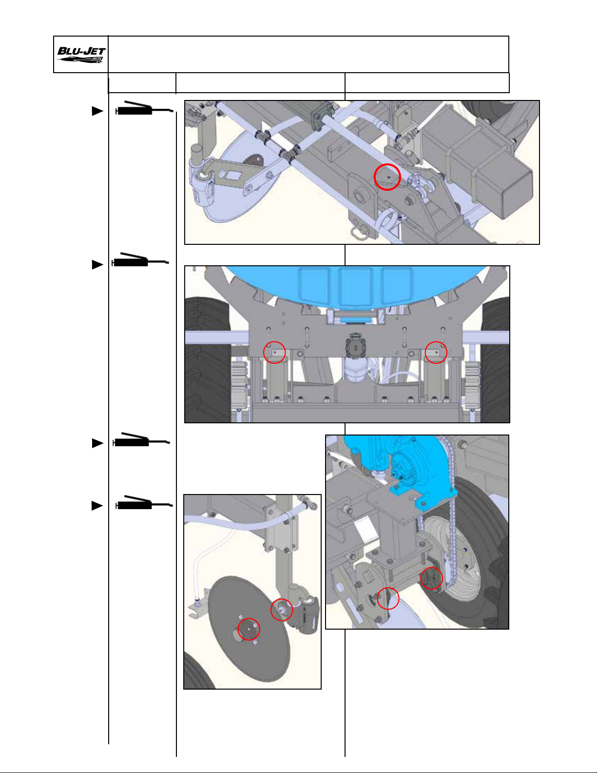
13. Grease wing hinges
14. Grease lift arm pivots daily.
Lift arm
pivot
lubrication
daily
Pump
bearings
lubrication
daily
Coulter
pivot shaft
and hub
lubrication
Rear View
15. Grease the zerks on the
pillow block bearing at
the bottom of the pump
assembly.
14
16. Grease all coulter arm pivots
daily
Hub and spindle assembly
should be greased twice
seasonally
Page 17
Operating Instructions
AT2000
Task Procedures Illustrations
Safety
water tank
operation
and
maintenance
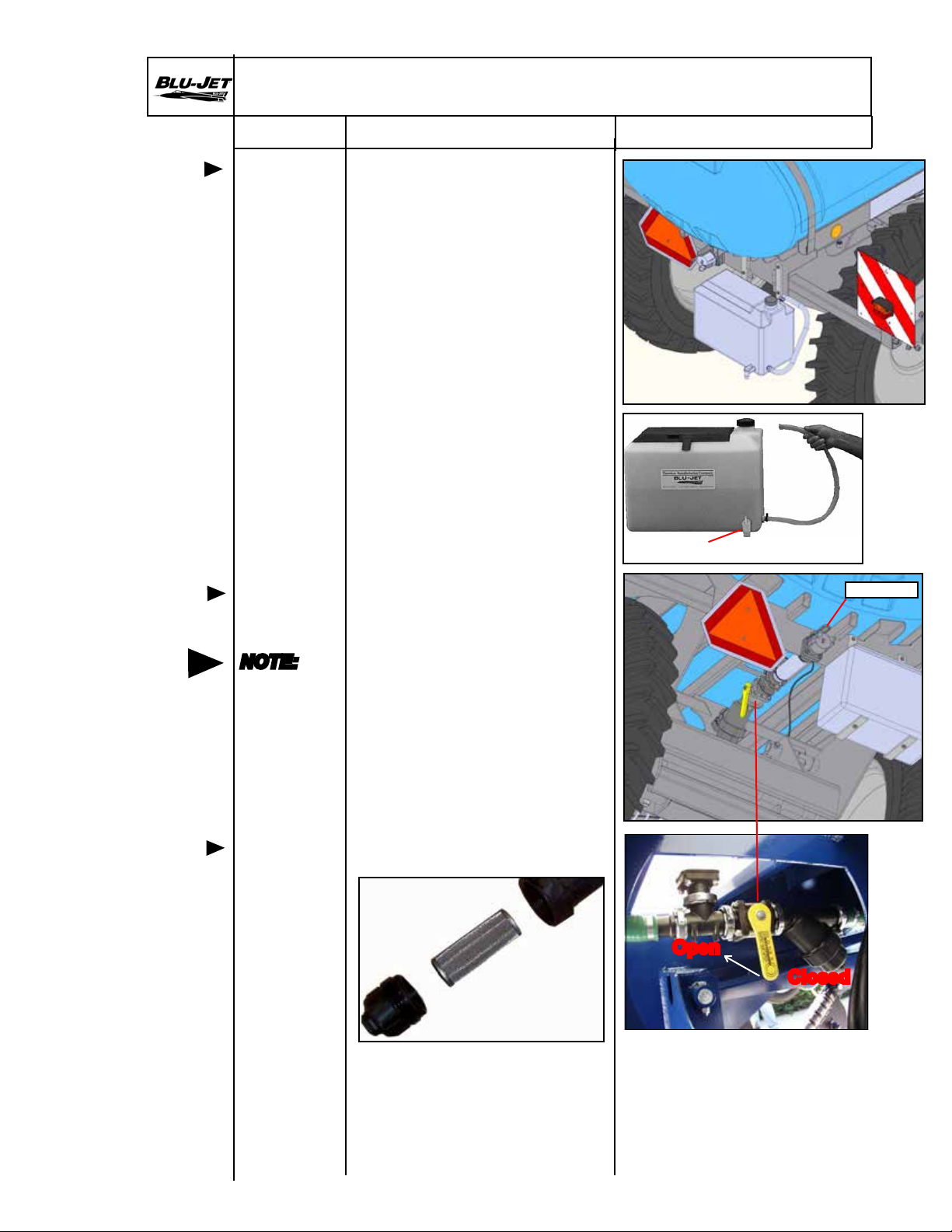
17. Location of Nine-gallon
safety water tank/toolbox.
Change water daily to provide
fresh clean water to ush
exposed skin or eyes.
Drain water daily in cold
temperatures to prevent
freezing and bursting tank.
18. In case of exposure to fertilizer,
open faucet or pull top
end of hose loose to ush
exposed part of body. Remove
contaminated clothes as soon
as possible.
Faucet
Bottom ll
valve
operation
NOTE:
Do not
engage
pump until
valve is
opened.
Bottom ll
plumbing
screen
19. Attach ll hose to ll port.
Close valve ahead of strainer.
Open ll valve. Fill tank.
Close ll valve.
20. Screen should be checked
and cleaned periodically.
Fill Valve
Open
Closed
15
Page 18

Operating Instructions
Pump Setting
AT2000
Task Procedures Illustrations
Pump
setting
NOTE:
Consult
pump manual
for setting
instructions
1. Read pump manual
for rate setting
instructions.
2. Loosen pump setting
hex nut.
3. Place pump wrench
on notched sprocket.
Dial in setting from
pump setting chart.
Hex nut
4. Tighten hex nut to
secure pump setting.
16
Page 19

High Pressure Coulter Injection System Nozzle Calibration
Work sheet
AT2000
Task Procedures Illustrations
Calibration of these systems involves two separate sets of calculations. The
rst being a procedure of setting rate and the second being a procedure of
obtaining system pressure.
FIRST: These systems utilize a positive-displacement, ground-driven,
piston pump to establish the GPA (gallon per acre) rate.
Because the pump is ground-driven, this rate will be very
consistent provided you do not exceed the pumps capacity or
pressure ratings (120 PSI Maximum).
SECOND: The injection system nozzles are what determine system
operation pressure at a particular ow rate and ground speed.
Because the system requires nozzle pressure in the 60 PSI to
120 PSI range to inject fertilizer into the soil properly, it
becomes necessary to size the nozzle correctly to maintain
this 60-120 PSI optimum operating pressure at various
speeds. In effect, the operating speed is limited by the range
of pressure necessary for proper injection system operation.
Remember that nozzle size has no affect on rate, only system operating
pressure.
High Pressure Injection System Pump Calibration Work sheet
Step 1: Rate Calculation (gallons per acre)
Actual pounds of nitrogen per acre desired percent
of nitrogen in solution equals pounds of solution per
acre
Actual N % of N = lbs. solution per acre
Examples:
100 lbs. of actual N desired .28 (% of N in solution) = 357 lbs. per acre
100 lbs. of actual N desired .32 (% of N in solution) = 312 lbs. per acre
Step 2: Pounds per acre of solution weight per gallon of solution equal GPA
(GPA= gallons per acre of solution)
lbs. solution per acre weight per gallon = GPA
Examples:
357 lbs. of 28% N solution 10.65 lbs. per gallon = 33.5 GPA
312 lbs. of 32% N solution 11.4 lbs. per gallon = 27.37 GPA
Step 3: Use the John Blue, pump setting, slide-rule chart. The standard
BLU-JET sprocket combination is 18 to 50.
.
-
.
.
-
.
.
-
.
.
-
.
.
-
.
.
-
.
.
-
.
-
.
.
Step 4: Loaded Radius:
We recommend using a loaded radius of 10” for the standard
BLU-JET tire drive wheel when used with the John Blue
LM 4450 pump.
Add 1/2” to the loaded radius if soil builds up on the small tire in wet
conditions.
17
Page 20

High Pressure Coulter Injection System Nozzle Calibration
Work Sheet
AT2000
Task Procedures Illustrations
Step 5: Swath width is the number of rows being applied (Example: A 15 row
30” machine will cover 16 rows.) times the spacing between the rows.
Rows x Spacing = Swath width
16 rows x 30” = 480” (swath width)
Step 6: Example:
1. Using the chart, align loaded radius (10”) with 18 to 50 sprocket
combination setting.
2. Using the chart, align swath width (480”) with arrow under
sprocket ratio.
3. Using the chart, GPA rate (LM 4450) pump) from step 2 above
will align with correct pump setting.
Once the correct pump setting has been obtained from the pump calibration
work sheet it becomes necessary to select a nozzle size that will result in a
system operating pressure that falls within the recommended range of 60 PSI
to 120 PSI. It is important to remember that GPA rate will not be affected by
changing nozzle sizes. The only way the GPA rate will change is if you
change pump settings. A gauge is provided to double check calculations
and monitor pressure during operation.
To simplify calibration we supplied a chart based on 28% nitrogen solution
in 30” row spacings.
Example: Using the 30” spacing chart, with 7 MPH as the target operating
speed and 115 lbs. N/acre as the target rate; you can see that nozzle size
4916-95 will produce 80 PSI @ 7 MPH. Also if you look under the 8 MPH
column you will see that this nozzle size will produce 100 PSI.
It is recommended that a mid-range pressure of 80 to 100 PSI is used to
allow for speed variances in eld operation, if possible.
It is recommended that the stream stabilizer nozzle inserts always be used
with these nozzles to improve the solid-stream characteristics of the spray
pattern and consequently the injection and over spray reduction charac-
teristics of nozzle. These stainless steel nozzle orices are commercially
available almost everywhere and there are several sizes available between
those on our chart if needed.
It is recommended that a ne line (80 mesh) stainer be used on extremely
low rate applications to prevent plugging nozzles.
18
Page 21

Blank Calibration
Work Sheet
AT2000
Task Procedures Illustrations
19
Page 22
Operating Instructions
Rate Orice Installation
AT2000
Task Procedures Illustrations
Pump
setting
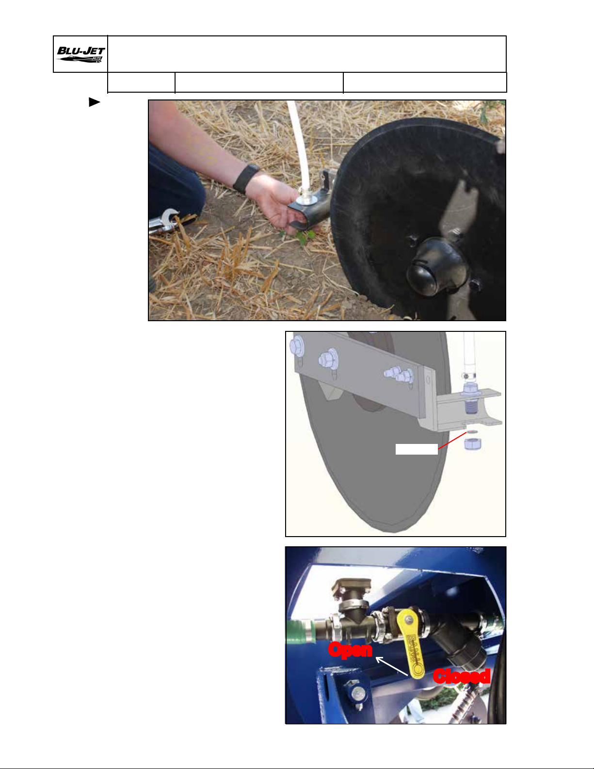
1. Consult row spacing
rate chart for orice
size.
2. Remove nozzle nut
and insert orice.
3. Open tank valve in the
eld.
Orice
Open
20
Closed
Page 23
Operating Instructions
AT2000
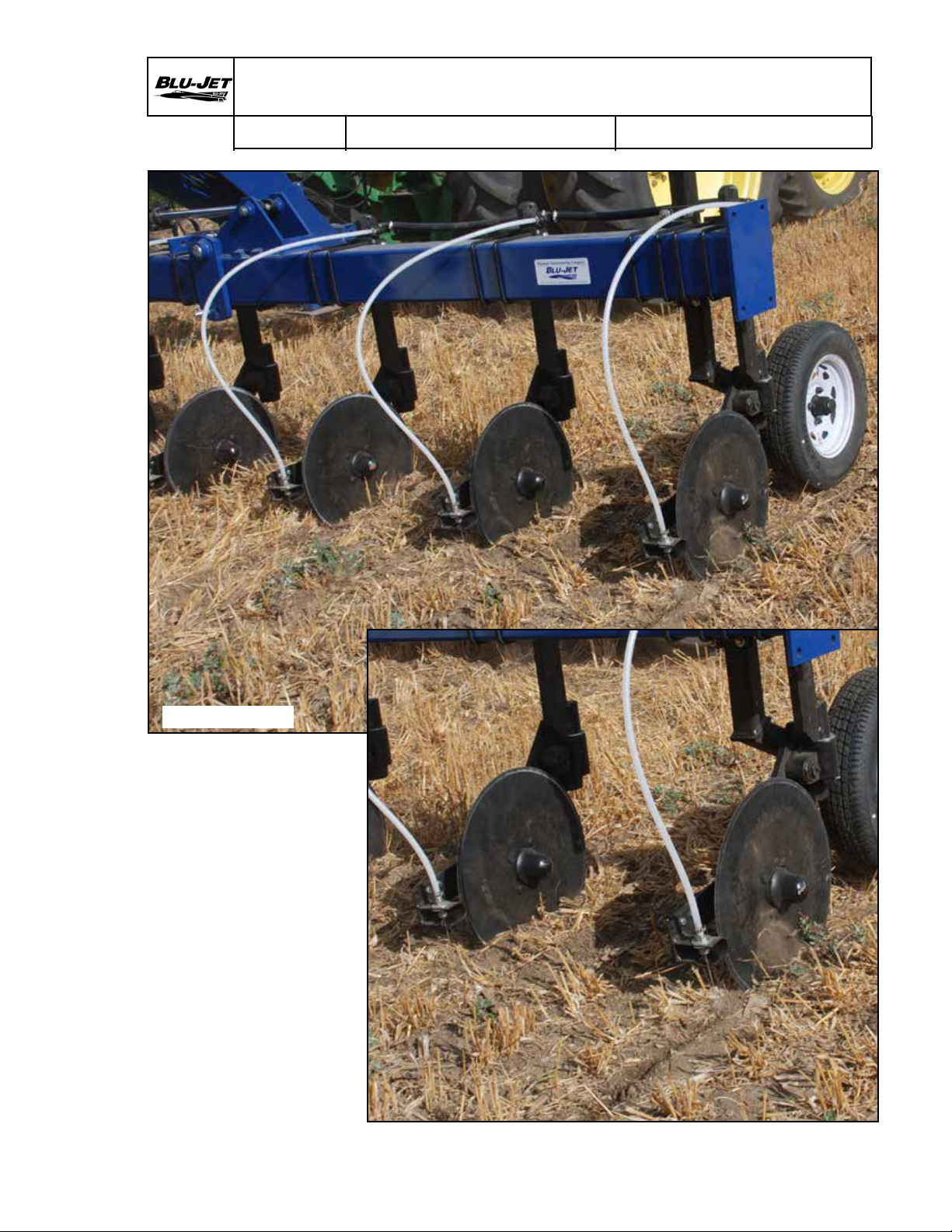
Task Procedures Illustrations
Generic Photo
1. Travel a few meters and
check blade depth.
4” (10 cm)
Adjust gauge wheels or
coulters to achieve the
4” (10 cm) depth.
2. Check all nozzles for
stream of liquid behind
blade.
3. Make adjustment to
nozzle assembly so
stream is in line with
the blade trench.
21
Page 24

22 Inch Spacing Rate Chart
Orice # PSI
4916 49
4916 57
*4916 63
*4916 70
*4916 78
*4916 86
*4916 95
4916 107
4916 120
AT2000
Task Procedures Illustrations
Gallons per Acre
60
80
100
120
60
80
100
120
60
80
100
120
60
80
100
120
60
80
100
120
60
80
100
120
60
80
100
120
60
80
100
120
60
80
100
120
GPM
10.65 lb./gal
28%
0.320
0.369
0.413
0.452
0.432
0.499
0.558
0.612
0.528
0.610
0.682
0.747
0.652
0.753
0.842
0.922
0.810
0.935
1.045
1.145
0.984
1.137
1.271
1.392
1.201
1.387
1.551
1.699
1.524
1.760
1.967
2.155
1.917
2.213
2.474
2.710
5
mph6mph7mph8mph9mph10mph11mph12mph
17.3 14.4 12.3 10.8 9.6 8.6 7.8 7.2
19.9 16.6 14.2 12.5 11.1 10.0 9.1 8.3
22.3 18.6 15.9 13.9 12.4 11.1 10.1 9.3
24.4 20.3 17.4 15.3 13.6 12.2 11.1 10.2
23.4 19.5 16.7 14.6 13.0 11.7 10.6 9.7
27.0 22.5 19.3 16.9 15.0 13.5 12.3 11.2
30.1 25.1 21.5 18.8 16.7 15.1 13.7 12.6
33.0 27.5 23.6 20.6 18.3 16.5 15.0 13.8
28.5 23.8 20.4 17.8 15.8 14.3 13.0 11.9
32.9 27.4 23.5 20.6 18.3 16.5 15.0 13.7
36.8 30.7 26.3 23.0 20.5 18.4 16.7 15.3
40.3 33.6 28.8 25.2 22.4 20.2 18.3 16.8
35.2 29.3 25.2 22.0 19.6 17.6 16.0 14.7
40.7 33.9 29.0 25.4 22.6 20.3 18.5 16.9
45.5 37.9 32.5 28.4 25.3 22.7 20.7 18.9
49.8 41.5 35.6 31.1 27.7 24.9 22.6 20.8
43.7 36.4 31.2 27.3 24.3 21.9 19.9 18.2
50.5 42.1 36.1 31.6 28.1 25.2 23.0 21.0
56.5 47.0 40.3 35.3 31.4 28.2 25.7 23.5
61.8 51.5 44.2 38.6 34.4 30.9 28.1 25.8
53.2 44.3 38.0 33.2 29.5 26.6 24.2 22.1
61.4 51.1 43.8 38.4 34.1 30.7 27.9 25.6
68.6 57.2 49.0 42.9 38.1 34.3 31.2 28.6
75.2 62.6 53.7 47.0 41.8 37.6 34.2 31.3
64.9 54.1 46.3 40.5 36.0 32.4 29.5 27.0
74.9 62.4 53.5 46.8 41.6 37.4 34.0 31.2
83.7 69.8 59.8 52.3 46.5 41.9 38.1 34.9
91.7 76.4 65.5 57.3 51.0 45.9 41.7 38.2
82.3 68.6 58.8 51.4 45.7 41.1 37.4 34.3
95.0 79.2 67.9 59.4 52.8 47.5 43.2 39.6
106.2 88.5 75.9 66.4 59.0 53.1 48.3 44.3
116.4 97.0 83.1 72.7 64.7 58.2 52.9 48.5
103.5 86.2 73.9 64.7 57.5 51.7 47.0 43.1
119.5 99.6 85.4 74.7 66.4
133.6 111. 3 95.4 83.5 74.2 66.8 60.7 55.7
146.4 122.0 104.5 91.5 81.3 73.2 66.5 61.0
22 Inch Spacing
59.8 54.3 49.8
e 4916 series of orices are available in many sizes falling between those listed on this chart.
* Standard equipment sizes.
22
Page 25

30 Inch Spacing Rate Chart
AT2000
Orice # PSI mph mph mph mph mph mph mph mph
4916 49
4916 57
*4916 63
*4916 70
*4916 78
*4916 86
*4916 95
4916 107
4916 120
Task Procedures Illustrations
Gallons per Acre 30 Inch Spacing
GPM
10.65 lb./gal
28%
60 0.320 12.7 10.5 9.0 7.9 7.0 6.3 5.8 5.3
80 0.369 14.6 12.2 10.4 9.1 8.1 7.3 6.6 6.1
100 0.413 16.3 13.6 11.7 10.2 9.1 8.2 7.4 6.8
120 0.452 17.9 14.9 12.8 11.2 9.9 8.9 8.1 7.5
60 0.432 17.1 14.3 12.2 10.7 9.5 8.6 7.8 7.1
80 0.499 19.8 16.5 14.1 12.4 11.0 9.9 9.0 8.2
100 0.558 22.1 18.4 15.8 13.8 12.3 11.1 10.0 9.2
120 0.612 24.2 20.2 17.3 15.1 13.5 12.1 11.0 10.1
60 0.528 20.9 17.4 14.9 13.1 11.6 10.5 9.5 8.7
80 0.610 24.2 20.1 17.3 15.1 13.4 12.1 11.0 10.1
100 0.682 27.0 22.5 19.3 16.9 15.0 13.5 12.3 11.3
120 0.747 29.6 24.7 21.1 18.5 16.4 14.8 13.4 12.3
60 0.652 25.8 21.5 18.4 16.1 14.3 12.9 11.7 10.8
80 0.753 29.8 24.9 21.3 18.6 16.6 14.9 13.6 12.4
100 0.842 33.3 27.8 23.8 20.8 18.5 16.7 15.2 13.9
120 0.922 36.5 30.4 26.1 22.8 20.3 18.3 16.6 15.2
60 0.810 32.1 26.7 22.9 20.0 17.8 16.0 14.6 13.4
80 0.935 37.0 30.9 26.4 23.1 20.6 18.5 16.8 15.4
100 1.045 41.4 34.5 29.6 25.9 23.0 20.7 18.8 17.2
120 1.145 45.3 37.8 32.4 28.3 25.2 22.7 20.6 18.9
60 0.984 39.0 32.5 27.8 24.4 21.7 19.5 17.7 16.2
80 1.137 45.0 37.5 32.2 28.1 25.0 22.5 20.5 18.8
100 1.271 50.3 41.9 35.9 31.5 28.0 25.2 22.9 21.0
120 1.392 55.1 45.9 39.4 34.5 30.6 27.6 25.1 23.0
60 1.201 47.6 39.6 34.0 29.7 26.4 23.8 21.6 19.8
80 1.387 54.9 45.8 39.2 34.3 30.5 27.5 25.0 22.9
100 1.551 61.4 51.2 43.9 38.4 34.1 30.7 27.9 25.6
120 1.699 67.3 56.1 48.1 42.0 37.4 33.6 30.6 28.0
60 1.524 60.3 50.3 43.1 37.7 33.5 30.2 27.4 25.1
80 1.760 69.7 58.1 49.8 43.5 38.7 34.8 31.7 29.0
100 1.967 77.9 64.9 55.6 48.7 43.3 39.0 35.4 32.5
120 2.155 85.3 71.1 61.0 53.3 47.4 42.7 38.8 35.6
60 1.917 75.9 63.2 54.2 47.4 42.2 37.9 34.5 31.6
80 2.213 87.6 73.0 62.6 54.8 48.7 43.8 39.8 36.5
100 2.474
120 2.710 107.3 89.4 76.7 67.1 59.6 53.7 48.8 44.7
5 6 7 8 9 10 11 12
98.0 81.7 70.0 61.2 54.4 49.0 44.5 40.8
e 4916 series of orices are available in many sizes falling between those listed on this chart.
* Standard equipment sizes.
23
Page 26

36 Inch Spacing Rate Chart
AT2000
Orice # PSI
4916 49
4916 57
*4916 63
*4916 70
*4916 78
*4916 86
*4916 95
4916 107
4916 120
Task Procedures Illustrations
GPM
10.65 lb./gal
28%
60 0.320 10.5 8.8 7.5 6.6 5.9 5.3 4.8 4.4
80 0.369 12.2 10.1 8.7 7.6 6.8 6.1 5.5 5.1
100 0.413 13.6 11.3 9.7 8.5 7.6 6.8 6.2 5.7
120 0.452 14.9 12.4 10.7 9.3 8.3 7.5 6.8 6.2
60 0.432 14.3 11.9 10.2 8.9 7.9 7.1 6.5 5.9
80 0.499 16.5 13.7 11.8 10.3 9.2 8.2 7.5 6.9
100 0.558 18.4 15.4 13.2 11.5 10.2 9.2 8.4 7.7
120 0.612 20.2 16.8 14.4 12.6 11.2 10.1 9.2 8.4
60 0.528 17.4 14.5 12.5 10.9 9.7 8.7 7.9 7.3
80 0.610 20.1 16.8 14.4 12.6 11.2 10.1 9.1 8.4
100 0.682 22.5 18.8 16.1 14.1 12.5 11.3 10.2 9.4
120 0.747 24.7 20.5 17.6 15.4 13.7 12.3 11.2 10.3
60 0.652 21.5 17.9 15.4 13.5 12.0 10.8 9.8 9.0
80 0.753 24.9 20.7 17.8 15.5 13.8 12.4 11.3 10.4
100 0.842 27.8 23.2 19.8 17.4 15.4 13.9 12.6 11.6
120 0.922 30.4 25.4 21.7 19.0 16.9 15.2 13.8 12.7
60 0.810 26.7 22.3 19.1 16.7 14.8 13.4 12.1 11.1
80 0.935 30.9 25.7 22.0 19.3 17.1 15.4 14.0 12.9
100 1.045 34.5 28.7 24.6 21.6 19.2 17.2 15.7 14.4
120 1.145 37.8 31.5 27.0 23.6 21.0 18.9 17.2 15.7
60 0.984 32.5 27.1 23.2 20.3 18.0 16.2 14.8 13.5
80 1.137 37.5 31.3 26.8 23.4 20.8 18.8 17.0 15.6
100 1.271 41.9 34.9 30.0 26.2 23.3 21.0 19.1 17.5
120 1.392 45.9 38.3 32.8 28.7 25.5 23.0 20.9 19.1
60 1.201 39.6 33.0 28.3 24.8 22.0 19.8 18.0 16.5
80 1.387 45.8 38.1 32.7 28.6 25.4 22.9 20.8 19.1
100 1.551 51.2 42.6 36.6 32.0 28.4 25.6 23.3 21.3
120 1.699 56.1 46.7 40.0 35.0 31.1 28.0 25.5 23.4
60 1.524 50.3 41.9 35.9 31.4 27.9 25.1 22.9 21.0
80 1.760 58.1 48.4 41.5 36.3 32.3 29.0 26.4 24.2
100 1.967 64.9 54.1 46.4 40.6 36.1 32.5 29.5 27.0
120 2.155 71.1 59.3 50.8 44.4 39.5 35.6 32.3 29.6
60 1.917 63.2 52.7 45.2 39.5 35.1 31.6 28.7 26.4
80 2.213 73.0 60.9 52.2 45.6 40.6 36.5 33.2 30.4
100
120 2.710 89.4 74.5 63.9 55.9 49.7 44.7 40.7 37.3
2.474 81.7 68.0 58.3 51.0 45.4 40.8 37.1 34.0
5 6 7 8 9 10 11 12
mph mph mph mph mph mph mph mph
Gallons per Acre
36 Inch Spacing
e 4916 series of orices are available in many sizes falling between those listed on this chart.
* Standard equipment sizes.
24
Page 27

38 Inch Spacing Rate Chart
AT2000
Orice # PSI
4916 49
4916 57
*4916 63
*4916 70
*4916 78
*4916 86
*4916 95
4916 107
4916 120
Task Procedures Illustrations
Gallons per Acre
GPM
10.65 lb./gal
28%
60 0.320 10.0 8.3 7.1 6.2 5.6 5.0 4.5 4.2
80 0.369 11.5 9.6 8.2 7.2 6.4 5.8 5.2 4.8
100 0.413 12.9 10.7 9.2 8.1 7.2 6.4 5.9 5.4
120 0.452 14.1 11.8 10.1 8.8 7.8 7.1 6.4 5.9
60 0.432 13.5 11.3 9.7 8.4 7.5 6.8 6.1 5.6
80 0.499 15.6 13.0 11.2 9.8 8.7 7.8 7.1 6.5
100 0.558 17.5 14.5 12.5 10.9 9.7 8.7 7.9 7.3
120 0.612 19.1 15.9 13.7 11.9 10.6 9.6 8.7 8.0
60 0.528 16.5 13.8 11.8 10.3 9.2 8.3 7.5 6.9
80 0.610 19.1 15.9 13.6 11.9 10.6 9.5 8.7 7.9
100 0.682 21.3 17.8 15.2 13.3 11.8 10.7 9.7 8.9
120 0.747 23.4 19.5 16.7 14.6 13.0 11.7 10.6 9.7
60 0.652 20.4 17.0 14.6 12.7 11.3 10.2 9.3 8.5
80 0.753 23.5 19.6 16.8 14.7 13.1 11.8 10.7 9.8
100 0.842 26.3 21.9 18.8 16.5 14.6 13.2 12.0 11.0
120 0.922 28.8 24.0 20.6 18.0 16.0 14.4 13.1 12.0
60 0.810 25.3 21.1 18.1 15.8 14.1 12.7 11.5 10.5
80 0.935 29.2 24.4 20.9 18.3 16.2 14.6 13.3 12.2
100 1.045 32.7 27.2 23.3 20.4 18.2 16.3 14.9 13.6
120 1.145 35.8 29.8 25.6 22.4 19.9 17.9 16.3 14.9
60 0.984 30.8 25.6 22.0 19.2 17.1 15.4 14.0 12.8
80 1.137 35.5 29.6 25.4 22.2 19.7 17.8 16.2 14.8
100 1.271 39.7 33.1 28.4 24.8 22.1 19.9 18.1 16.6
120 1.392 43.5 36.3 31.1 27.2 24.2 21.8 19.8 18.1
60 1.201 37.6 31.3 26.8 23.5 20.9 18.8 17.1 15.6
80 1.387 43.4 36.1 31.0 27.1 24.1 21.7 19.7 18.1
100 1.551 48.5 40.4 34.6 30.3 26.9 24.2 22.0 20.2
120 1.699 53.1 44.3 37.9 33.2 29.5 26.6 24.1 22.1
60 1.524 47.6 39.7 34.0 29.8 26.5 23.8 21.7 19.8
80 1.760 55.0 45.8 39.3 34.4 30.6 27.5 25.0 22.9
100 1.967 61.5 51.3 43.9 38.4 34.2 30.8 28.0 25.6
120 2.155 67.4 56.1 48.1 42.1 37.4 33.7 30.6 28.1
60 1.917 59.9 49.9 42.8 37.4 33.3 30.0 27.2 25.0
80 2.213 69.2 57.7 49.4 43.2 38.4 34.6 31.4 28.8
100
120 2.710 84.7 70.6 60.5 53.0 47.1 42.4 38.5 35.3
2.474 77.4 64.5 55.3 48.3 43.0 38.7 35.2 32.2
5 6 7 8 9 10 11 12
mph mph mph mph mph mph mph mph
38 Inch Spacing
e 4916 series of orices are available in many sizes falling between those listed on this chart.
* Standard equipment sizes.
25
Page 28

40 Inch Spacing Rate Chart
AT2000
Orice # PSI
4916 49
4916 57
*4916 63
*4916 70
*4916 78
*4916 86
*4916 95
4916 107
4916 120
Task Procedures Illustrations
GPM
10.65 lb./gal
28%
60 0.320 9.5 7.9 6.8 5.9 5.3 4.7 4.3 4.0
80 0.369 11.0 9.1 7.8 6.8 6.1 5.5 5.0 4.6
100 0.413 12.3 10.2 8.8 7.7 6.8 6.1 5.6 5.1
120 0.452 13.4 11.2 9.6 8.4 7.5 6.7 6.1 5.6
60 0.432 12.8 10.7 9.2 8.0 7.1 6.4 5.8 5.4
80 0.499 14.8 12.4 10.6 9.3 8.2 7.4 6.7 6.2
100 0.558 16.6 13.8 11.8 10.4 9.2 8.3 7.5 6.9
120 0.612 18.2 15.1 13.0 11.4 10.1 9.1 8.3 7.6
60 0.528 15.7 13.1 11.2 9.8 8.7 7.8 7.1 6.5
80 0.610 18.1 15.1 12.9 11.3 10.1 9.1 8.2 7.5
100 0.682 20.3 16.9 14.5 12.7 11.3 10.1 9.2 8.4
120 0.747 22.2 18.5 15.8 13.9 12.3 11.1 10.1 9.2
60 0.652 19.4 16.1 13.8 12.1 10.8 9.7 8.8 8.1
80 0.753 22.4 18.6 16.0 14.0 12.4 11.2 10.2 9.3
100 0.842 25.0 20.8 17.9 15.6 13.9 12.5 11.4 10.4
120 0.922 27.4 22.8 19.6 17.1 15.2 13.7 12.5 11.4
60 0.810 24.0 20.0 17.2 15.0 13.4 12.0 10.9 10.0
80 0.935 27.8 23.1 19.8 17.4 15.4 13.9 12.6 11.6
100 1.045 31.0 25.9 22.2 19.4 17.2 15.5 14.1 12.9
120 1.145 34.0 28.3 24.3 21.3 18.9 17.0 15.5 14.2
60 0.984 29.2 24.4 20.9 18.3 16.2 14.6 13.3 12.2
80 1.137 33.8 28.1 24.1 21.1 18.8 16.9 15.3 14.1
100 1.271 37.7 31.5 27.0 23.6 21.0 18.9 17.2 15.7
120 1.392 41.3 34.5 29.5 25.8 23.0 20.7 18.8 17.2
60 1.201 35.7 29.7 25.5 22.3 19.8 17.8 16.2 14.9
80 1.387 41.2 34.3 29.4 25.7 22.9 20.6 18.7 17.2
100 1.551 46.1 38.4 32.9 28.8 25.6 23.0 20.9 19.2
120 1.699 50.5 42.0 36.0 31.5 28.0 25.2 22.9 21.0
60 1.524 45.3 37.7 32.3 28.3 25.1 22.6 20.6 18.9
80 1.760 52.3 43.5 37.3 32.7 29.0 26.1 23.8 21.8
100 1.967 58.4 48.7 41.7 36.5 32.5 29.2 26.6 24.3
120 2.155 64.0 53.3 45.7 40.0 35.6 32.0 29.1 26.7
60 1.917 56.9 47.4 40.7 35.6 31.6 28.5 25.9 23.7
80 2.213 65.7 54.8 46.9 41.1 36.5 32.9 29.9 27.4
100
120 2.710 80.5 67.1 57.5 50.3 44.7 40.3 36.6 33.5
2.474 73.5 61.2 52.5 45.9 40.8 36.7 33.4 30.6
Gallons per Acre
40 Inch Spacing
5 6 7 8 9 10 11 12
mph mph mph mph mph mph mph mph
e 4916 series of orices are available in many sizes falling between those listed on this chart.
* Standard equipment sizes.
26
Page 29
22 Inch Row Spacing (9 Row 22”) (56 cm)
AT2000
Task Procedures Illustrations
88"
NOTE:
Coulter
shank to
the rear
this row
only
AAM2730
COULTER
BACK 1x
22"
36"
44"
66"
82-3/4"
88"
27
Page 30
22 Inch Row Spacing (11 Row 22”) (56 cm)
AT2000
Task Procedures Illustrations
88"
NOTE:
Coulter
shank to
the rear
this row
only
AAM2730
COULTER
BACK 1x
28
22"
36"
44"
66"
82-3/4"
88"
110"
Page 31

22 Inch Row Spacing (13 Row 22”) (56 cm)
AT2000
Task Procedures Illustrations
88"
NOTE:
Coulter
shank to
the rear
this row
only
AAM2730
COULTER
BACK 1x
22"
36"
44"
66"
82-1/2"
88"
110"
132"
29
Page 32

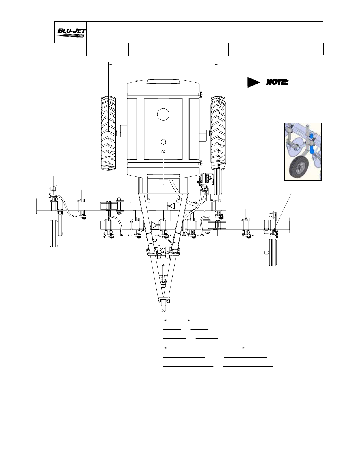
30 Inch Row Spacing (7 Row 30”) (76 cm)
AT2000
Task Procedures Illustrations
60"
NOTE:
Coulter
shank to
the rear
this row
only
AAM2730
COULTER
BACK 1x
30
30"
41-3/4"
60"
84-3/4"
90"
Page 33

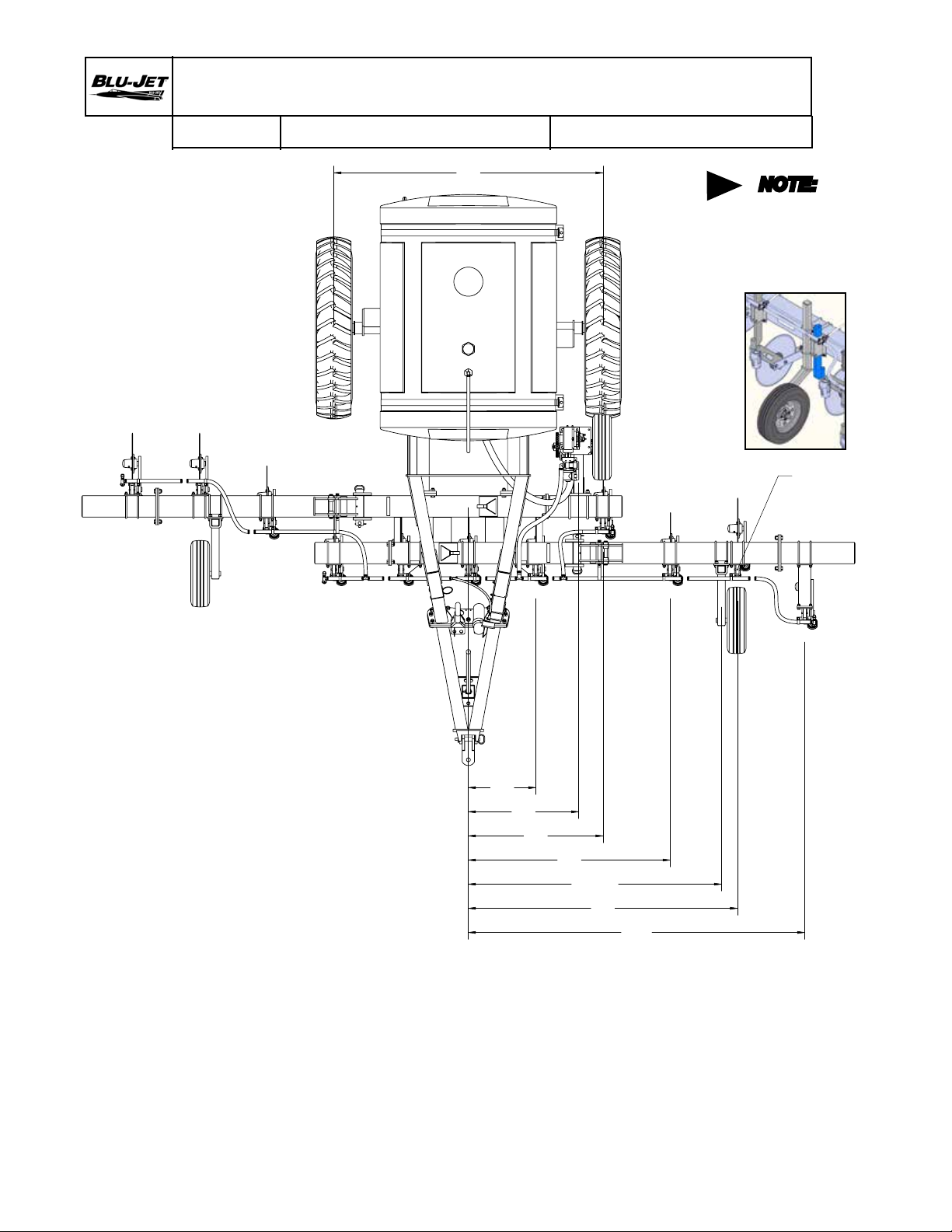
30 Inch Row Spacing (9 Row 30”) (76 cm)
AT2000
AT2000
Task Procedures Illustrations
60"
NOTE:
Coulter
shank to
the rear
this row
only
AAM2730
COULTER
BACK 1x
30"
41-1/2"
60"
84-3/4"
90"
120"
31
Page 34

30 Inch Row Spacing (11 Row 30”) (76 cm)
AT2000
Task Procedures Illustrations
NOTE:
Coulter
shank to
the rear
this row
only
AAM2730
COULTER
BACK 1x
150"
120"
90"
84-3/4"
60"
60"
AT2000
30"
41-3/4"
32
11 ROW 30"
Page 35

36 Inch Row Spacing (8 Row 36”) (91,4 cm)
AT2000
Task Procedures Illustrations
NOTE:
Coulter
shank to
the rear
each side
AAM2730
COULTER
BACK 2x
10"
134"
72"
66-3/4"
46"
31"
78"
AT2000
8 ROW 36"
LIQUID APPLICATOR
33
Page 36

38 Inch Row Spacing (7 Row 38”) (97,5 cm)
80"
AT2000
Task Procedures Illustrations
NOTE:
Coulter
shank to
the rear
AAM2730
COULTER
this row
only
BACK 1x
125"
87"
81-3/4"
49"
32"
11"
AT2000
LIQUID APPLICATOR
34
8 ROW 38"
Page 37

40 Inch Row Spacing (7 Row 40”) (101,6 cm)
AT2000
80"
Task Procedures Illustrations
NOTE:
Coulter
shank to
AAM2730
COULTER
the rear
this row
only
BACK 1x
132"
92"
86-3/4"
52"
32"
12"
AT2000
35
Page 38

AT2000
AT2000
Task Procedures Illustrations
BOM ID Qty Item No Metric Description
1 1 32220930 AT2000 9 ROW 30” LIQUID APPLICATOR
2 1 32000009 PUMP DRIVE KIT, 32 TOOTH SPROCKET
3 1 32000930 AT2000 9 ROW 30” STANDARD TOOLBAR
4 9 AAM3353 JETSTREAM LIQUID ASSEMBLY, TEE-JET CHECK, 1 ROW
5 1 CP2568 PUMP, SINGLE PISTON, NGP-7055
36
Page 39

AT2000 Shipping Assembly (32000000)
AT2000
Task Procedures Illustrations
BOM ID Qty Item No Description
1 1 32000000 AT2000, SHIPPING ASSEMBLY
2 1 32000001 AT2000 MAIN FRAME
3 1 AAM4872 ASSEMBLY, AT2000 CART WITH TANK
4 1 AM2144 HITCH, CLEVIS
5 1 AM2570 CRANK WITH GRIP, 80 DEGREE, THURSTON MANUFACTURING COMPANY BLUE
6 1 AM3705 JACK, AT2000, 9TWDL (TOP WIND DROP LEG)
7 1 AP2280 HOSE RETAINER, 6” X 4” (15,2 cm X 10,2 cm)
8 1 BP3003 NUT, HEX LOCK, 3/8”-16, GRADE 2, PLATED (9,5 mm)
9 2 BP3015 WASHER, FLAT, 3/8”, PLATED (9,5 mm)
10 2 BP3051 PIN, 1” X 6”, PLATED (2,5 cm X 15,2 cm)
11 1 BP3096 HEX CAP SCREW, 3/8”-16 X 2-1/2”, GRADE 5, PLATED (9,5 mm X 6,4 cm)
12 3 BP3097 HEX CAP SCREW, 5/8”-11 X 1-1/2”, GRADE 5, PLATED (15,9 mm X 3,8 cm)
13 8 BP3197 HEX CAP SCREW, 3/4”-10 X 2-1/2”, GRADE 8, PLATED (19,1 mm X 6,4 cm)
14 2 BP3205 MACHINERY BUSHING, 2-1/2” OD X 1-3/4” ID, 10 GAUGE, PLATED (6,4 cm X 4,4 cm X 3,4 mm)
15 3 BP3375 NUT, HEX LOCK, 5/8”-11, NYLOCK (15,9 mm)
16 8 BP3442 NUT, HEX LOCK, 3/4”-10, TOP LOCK, GRADE C, PLATED (19,1 mm)
17 2 BP3511 PIN, COTTER, 3/16” X 1-3/4” (4,8 mm X 4,4 cm)
18 1 32000002 WHEEL/AXLE, AT2000, ADJUSTABLE
19 1 32000004 AT2000 STANDARD TOOLBAR
20 1 32000005 BOTTOM FILL PLUMBING KIT, AT2000 TANK, 1 PUMP, 2’’ FILL (5,1 cm)
37
Page 40

AT2000 9 Row 30” (32220930)
AT2000
Task Procedures Illustrations
32220930
38
NOTE:
Close-up views
on the following
pages
38
Page 41

AT2000 9 Row 30” (32220930)
AT2000
BOM ID Qty Item No Description
1 1 32000930 AT2000, 9 Row 30” (76 cm) WITH STANDARD BUNDLES
2 1 32000000 AT2000, SHIPPING ASSEMBLY
3 1 32000010 MANIFOLD ASSEMBLY, AT2000, 3/4’’ EPDM HOSE, 9 ROW (1,9 cm)
4 2 33000112 single GAUGE WHEEL, 155/80R12 TIRE
5 1 AAM2398 HOSE END HOLDER, 2 HOSE, WITH U-BOLTS
5A 1 AM3425 BRACKET, HOSE HOLDER, 2 HOSE
5B 2 BP3045 U-BOLT, 3/8”-16 X 6”W X 5”L, PLATED (9,5 mm X 15,2 cm X 12,7 cm)
5C 4 CP2660 NUT, HEX LOCK, 3/8”-16, NYLOCK (9,5 mm)
6 1 AAM2422 TRANSPORT CHAIN KIT
6A 1 AP2150 TRANSPORT CHAIN
6B 1 BM3498 BUSHING, SAFETY CHAIN
6C 1 BP3051 PIN, 1” X 6”, PLATED (2,5 cm X 15,2 cm)
6D 1 BP3511 PIN, COTTER, 3/16” X 1-3/4” (4,8 mm X 4,4 cm)
7 9 AAM2730 COULTER, SUPER 1200, 23” SHANK, 1 ROW
8 9 AAM2821 COULTER, FLATBACK, CENTERED ASSEMBLY, 7” X 7” (17,8 cm X 17,8 cm)
9 2 AAM4873 WING EXTENSION KIT, 34” (86 cm)
10 1 AAM4875 FLATBACK EXTENSION WITH HARDWARE
11 2 AAM4876 WING EXTENSION KIT, 24” (70 cm)
12 1 AM3706 UTILITY PLATE
13 2 AM4015 HOSE RETAINER, CLOSED LOOP
14 2 AM4421 BRACKET, TANK MOUNT
15 1 AP2137 SAFETY TANK
16 9 AP2215 DECAL, BLU-JET, 3” X 8” (7,6 cm X 20,3 cm)
17 2 AP2564 DECAL, SAFETY PICTORIAL, FALLING FROM EQUIPMENT
18 2 AP2565 DECAL, SAFETY PICTORIAL, HIGH PRESSURE FLUID
19 4 AP2566 DECAL, SAFETY PICTORIAL, FALLING WING
20 1 AP2567 DECAL, SAFETY PICTORIAL, READ OPERATOR’S MANUAL
21 1 AP2568 DECAL, SAFETY PICTORIAL, SAFETY CHAIN
22 2 AP2569 DECAL, SAFETY PICTORIAL, CRUSHING HAZARD
23 2 AP2570 DECAL, AT2000
24 9 AP2840 COULTER BLADE 20”, SMOOTH (50,8 cm)
25 1 AP2850 PERFECT HITCH, CATEGORY III, BLACK
26 1 AP4254 MANUAL HOLDER, BLACK
27 4 BP3001 NUT, HEX, 3/8”-16, GRADE 2, PLATED (9,5 mm)
28 4 BP3002 WASHER, LOCK, 3/8”, PLATED (9,5 mm)
29 4 BP3005 HEX CAP SCREW, 3/8”-16 X 1-1/2”, GRADE 5, PLATED (9,5 mm X 3,8 cm)
30 2 BP3006 HEX CAP SCREW, 3/8”-16 X 1”, GRADE 5, PLATED (9,5 mm X 2,5 cm)
31 6 BP3108 HEX CAP SCREW, 5/16”-18 X 1”, GRADE 5, PLATED (7,9 mm X 2,5 cm)
32 6 BP3158 WASHER, LOCK, 5/16”, PLATED (7,9 mm)
33 6 BP3159 WASHER, FLAT, 5/16”, PLATED (7,9 mm)
34 2 BP3335 U-BOLT, 3/8”-16 X 7”W X 8”L, PLATED (9,5 mm X 17,8 cm X 20,3 cm)
35 1 BP3500 PIN, HAIR CLIP, 3/16” (4,8 mm)
36 6 CP2660 NUT, HEX LOCK, 3/8”-16, NYLOCK (9,5 mm)
37 1 AP2572 DECAL, HYDRAULIC CIRCUITS, AT2000
38 1 AP2574 DECAL, RAISE CENTER BEFORE FOLDING
Task Procedures Illustrations
NOTE:
Close-up views
on the following
pages
39
Page 42

AT2000 9 Row 30” (32220930)
AT2000
Task Procedures Illustrations
40
32220930
Page 43

AT2000 9 Row 30” (32220930)
AT2000
Task Procedures Illustrations
41
Page 44

AT2000 Main Frame (32000001)
AT2000
Task Procedures Illustrations
42
Page 45

AT2000 Main Frame (32000001)
AT2000
BOM ID Qty Item No Description
1 1 32000001 AT2000 MAIN FRAME
2 1 AAM4872 ASSEMBLY, AT2000 CART WITH TANK
3 1 AM3555 ARM, TOOLBAR LIFT, LEFT HAND
3A 1 BP3072 GREASE ZERK, 1/4”-28 (6,4 mm)
3B 1 BP3516 TENSION BUSHING, 1-1/4” X 1” X 1” OAL (3,2 cm X 2,5 cm X 2,5 cm)
4 1 AM3556 ARM, TOOLBAR LIFT, RIGHT HAND
4A 1 BP3072 GREASE ZERK, 1/4”-28 (6,4 mm)
4B 1 BP3516 TENSION BUSHING, 1-1/4” X 1” X 1” OAL (3,2 cm X 2,5 cm X 2,5 cm)
5 1 AM3701 FRAME, MAIN, AT2000
6 1 AM3702 TONGUE, AT2000
7 2 AM3703 TANK STRAP, 5 cm X 244 cm, POLYESTER WEBBING, BLUE
8 2 AM4432 BRACKET, TANK STRAP ADJUSTMENT, 5 cm STRAP
9 1 AP2573 LABEL, CE PRODUCT INFORMATION
10 1 AP4351 TANK, 2000 LITER ELLIPTICAL
11 2 BM3496 PIN, 1-3/4” X 10-3/4” OAL (4,4 cm X 27,3 cm)
12 4 BP3042 NUT, HEX, 1/2”-13, GRADE 2, PLATED (12,7 mm)
13 2 BP3135 HEX CAP SCREW, 5/8”-11 X 3-1/2”, GRADE 5, PLATED (15,9 mm X 8,9 cm)
14 11 BP3197 HEX CAP SCREW, 3/4”-10 X 2-1/2”, GRADE 8, PLATED (19,1 mm X 6,4 cm)
15 2 BP3217 HEX CAP SCREW, 1/2”-13 X 5”, FULL THREAD, GRADE 8, PLATED (12,7 mm X 12,7 cm)
16 2 BP3375 NUT, HEX LOCK, 5/8”-11, NYLOCK (15,9 mm)
17 11 BP3442 NUT, HEX LOCK, 3/4”-10, TOP LOCK, GRADE C, PLATED (19,1 mm)
18 1 AM2144 HITCH, CLEVIS
19 1 AM2570 CRANK WITH GRIP, 80 DEGREE
20 1 AM3705 JACK, AT2000, 9TWDL (TOP WIND DROP LEG)
21 1 AP2280 HOSE RETAINER, 6” X 4” (15,2 cm X 10,2 cm)
22 1 BP3003 NUT, HEX LOCK, 3/8”-16, GRADE 2, PLATED (9,5 mm)
23 2 BP3015 WASHER, FLAT, 3/8”, PLATED (9,5 mm)
24 2 BP3051 PIN, 1” X 6”, PLATED (2,5 cm X 15,2 cm)
25 1 BP3096 HEX CAP SCREW, 3/8”-16 X 2-1/2”, GRADE 5, PLATED (9,5 mm X 6,4 cm)
26 3 BP3097 HEX CAP SCREW, 5/8”-11 X 1-1/2”, GRADE 5, PLATED (15,9 mm X 3,8 cm)
27 8 BP3197 HEX CAP SCREW, 3/4”-10 X 2-1/2”, GRADE 8, PLATED (19,1 mm X 6,4 cm)
28 2 BP3205 MACHINERY BUSHING, 2-1/2” OD X 1-3/4” ID, 10 GAUGE, PLATED (6,4 cm X 4,4 cm X 3,4 mm)
29 3 BP3375 NUT, HEX LOCK, 5/8”-11, NYLOCK (15,9 mm)
30 8 BP3442 NUT, HEX LOCK, 3/4”-10, TOP LOCK, GRADE C, PLATED (19,1 mm)
31 2 BP3511 PIN, COTTER, 3/16” X 1-3/4” (4,8 mm X 4,4 cm)
Task Procedures Illustrations
43
Page 46

AT2000 Main Frame (32000001)
AT2000
Task Procedures Illustrations
44
Page 47

AT2000 Main Frame (32000001)
AT2000
Task Procedures Illustrations
45
Page 48

AT2000 Adjustable Wheel/Axle (32000002)
AT2000
Task Procedures Illustrations
BOM ID Qty Item No Metric Description
1 1 32000002 AT2000 ADJUSTABLE WHEEL/AXLE
2 1 AAM2771 WHEEL, 12.4 X 38, 14 PLY 38 X 10 X 8, LEFT-HAND ASSEMBLY
2A 1 AP2790 VALVE STEM, METAL
2B 1 AP2867 TIRE, 12.4 X 38, 14 PLY, TRACTION GRIP
2C 1 AP4238 RIM, 38” X 10” X 8”, WHITE (96,5 cm X 25,4 cm X 20,3 cm)
3 1 AAM2772 WHEEL, 12.4 X 38, 14 PLY 38 X 10 X 8, RIGHT-HAND ASSEMBLY
3A 1 AP2790 VALVE STEM, METAL
3B 1 AP2867 TIRE, 12.4 X 38, 14 PLY, TRACTION GRIP
3C 1 AP4238 RIM, 38” X 10” X 8”, WHITE (96,5 cm X 25,4 cm X 20,3 cm)
4 2 AAM2891 ASSEMBLY, HUB & SPINDLE, 608(B) HUB, 2-3/4” X 23” SPINDLE, WITH
FLANGE LOCK NUT (7,0 cm X 58,4 cm)
5 2 AM3718 AXLE, AT2000, BOLT-ON
6 2 AM4597 HUB CAP STRAP
7 1 BP3050 WASHER, FLAT, 1/2”, PLATED (12,7 mm)
8 1 BP3128 HEX CAP SCREW, 1/2”-13 X 2-1/2”, GRADE 5 PLATED (12,7 mm X 6,4 cm)
9 16 BP3140 HEX CAP SCREW, 3/4”-10 X 2-1/2”, GRADE 5 PLATED (19,1 mm X 6,4 cm)
10 2 BP3144 HEX CAP SCREW, 3/4”-10 X 5”, GRADE 5 PLATED (19,1 mm X 12,7 cm)
11 18 BP3296 NUT, HEX LOCK, 3/4”-10, NYLOCK (19,1 mm)
12 1 BP3704 NUT, LOCK, NYLON INSERT, 1/2”-13 (12,7 mm)
46
Page 49

Hub and Spindle Assembly (AAM2891)
AT2000
Task Procedures Illustrations
BOM ID Qty Item No Description
1 1 AAM2891 ASSEMBLY, HUB & SPINDLE, 608(B) HUB, 2-3/4” X 23” SPINDLE, FLANGE LOCK NUT (7,0 cm X 58,4 cm)
2 1 AP2082 BEARING CONE, LM 501349
3 1 AP2122 COTTER PIN, 7/32” X 1-3/4” (0,6 cm X 4,4 cm)
4 1 AP2597 SPINDLE, 2-3/4” X 23” (7 cm X 58,4 cm)
5 1 AP2598 HUB WITH CUPS, 8 BOLT, WITH STUDS, 608301-8
5A 1 AP2086 BEARING CUP, LM 501310
5B 1 AP2598-Hub HUB, 8 BOLT, 608(B)
5C 1 AP2804 BEARING CUP, JLM 506810
5D 8 AP2814 BOLT, WHEEL STUD, 5/8”-18 X 2-1/4” (1,6 cm X 5,7 cm)
5E 1 BP3268 GREASE ZERK
6 1 AP2805 BEARING CONE, JLM 506849
7 1 AP2808 GREASE SEAL, CR 27394
8 1 AP2809 HUB CAP, 1609
9 1 AP2811 NUT, SPINDLE, 1”-14 (2,5 cm)
10 1 AP2812 WASHER, SPINDLE, 2-1/8” X 1-1/16” X .250” (5,4 cm X 2,7 cm X 0,6 cm)
11 8 BP3287 NUT, HEX LOCK, 5/8”-18 FLANGE, SPIRALOCK THREAD (1,6 cm)
47
Page 50

AT2000 Standard Toolbar (32000004)
AT2000
Task Procedures Illustrations
BOM ID Qty Item No Description
1 1 32000004 AT2000 STANDARD TOOLBAR
2 1 AM3707 TOOLBAR CENTER SECTION, AT2000
2A 2 BP3516 TENSION BUSHING, 1-1/4” X 1” X 1” OAL (3,2 cm X 2,5 cm X 2,5 cm)
3 2 AM3709 WING, STANDARD TOOLBAR, AT2000
4 4 AP2407 SNAP RING, 1” EXTERNAL, HEAVY DUTY (2,5 cm)
5 2 BM3485 PIN, 1-3/4” X 12-1/8” OAL, PLATED (4,4 cm X 30,8 cm)
6 2 BM3725 PIN, 1” X 7-1/2”, DOUBLE GROOVED (2,5 cm X 19,1 cm)
7 2 BP3135 HEX CAP SCREW, 5/8”-11 X 3-1/2”, GRADE 5, PLATED (15,9 mm X 8,9 cm)
8 4 BP3205 MACHINERY BUSHING, 2-1/2” OD X 1-3/4” ID, 10 GAUGE, PLATED (6,4 cm X 4,4 cm X 3,4 mm)
9 4 BP3215 MACHINERY BUSHING, 1-1/2” OD X 1” ID, 14 GAUGE, PLATED (3,8 cm X 2,5 cm 1,9 mm)
10 2 BP3375 NUT, HEX LOCK, 5/8”-11, NYLOCK (15,9 mm)
11 2 BP3500 PIN, HAIR CLIP, 3/16” (4,8 mm)
12 2 BP3510 PIN, 1” X 10”, HITCH, PLATED (2,5 cm X 25,4 cm)
13 1 PKG00246 HYDRAULIC KIT, AT2000
48
Page 51

AT2000 Standard Toolbar (PKG00246)
AT2000
Task Procedures Illustrations
BOM ID Qty Item No Description
1 1 PKG00246 HYDRAULIC KIT, AT2000
2 1 AM3713 HOSE HOLDER STRAP
3 2 AM4817 BRACKET, DEPTH COLLAR STORAGE
4 1 AM7518 HOSE HOLDER RETAINER
5 1 AP2871 HOSE RETAINER
6 6 BP3001 NUT, HEX, 3/8”-16, GRADE 2, PLATED (9,5 mm)
7 6 BP3002 WASHER, LOCK, 3/8”, PLATED (9,5 mm)
8 2 BP3003 NUT, HEX LOCK, 3/8”-16, GRADE 2, PLATED (9,5 mm)
9 1 BP3045 U-BOLT, 3/8”-16 X 6”W X 5”L, PLATED (9,5 mm X 15,2 cm X 12,7 cm)
10 2 BP3076 DEPTH COLLAR SET
11 2 BP3116 HEX CAP SCREW, 3/8”-16 X 3”, GRADE 5, PLATED (9,5 mm X 7,6 cm)
12 2 BP3335 U-BOLT, 3/8”-16 X 7”W X 8”L, PLATED (9,5 mm X 17,8 cm X 20,3 cm)
13 4 DP4004 TEE, 6MJ-6MJ-6MJ
14 15 DP4086 CABLE TIE 11-3/8” (28,9 cm)
15 8 DP4301 ADAPTER, 6MJ-8MSAE, 90 DEGREE
16 4 DP4383 COUPLER, PIONEER, 8MQBA-8FSAE
17 4 DP4394 ADAPTER, 8MSAE-6MJIC, 6400-6-8
18 2 DP4492 CYLINDER, HYDRAULIC, 3” X 20” (7,6 cm X 50,8 cm)
19 2 DP4516 CYLINDER, HYDRAULIC, 3” X 6” (7,6 cm X 15,2 cm)
20 2 DP5048 HOSE, HYDRAULIC, 1/4” X 22” (6,4 mm X 55,9 cm), 6FJX-6FJX
21 5 DP5054 HOSE, HYDRAULIC, 1/4” X 20” (6,4 mm X 50,8 cm), 6FJX-6FJX
22 2 DP5200 HOSE, HYDRAULIC, 3/8” X 202” (9,5 mm X 5,1M), 6FJX-8MSAE
23 1 DP5267 HOSE, HYDRAULIC, 1/4” X 32” (6,4 mm X 81,3 cm), 6FJX-6FJX
24 2 DP5268 HOSE, HYDRAULIC, 1/4” X 144” (6,4 mm X 3,66 m), 6FJX-6FJX
49
Page 52

Gauge Wheel Set (33000112)
AT2000
Task Procedures Illustrations
33000112 GAUGE WHEELS, AT GULL TOOLBAR, 155/80R12 TIRES
BOM ID Qty Item No Description
1 2 33000112 single GAUGE WHEEL, 155/80R12 TIRE
2 1 AM3546 ASSEMBLY, GAUGE WHEEL, LEFT HAND
3 1 AM3548 ASSEMBLY, GAUGE WHEEL, RIGHT HAND
4 2 AM3626 GAUGE WHEEL MOUNT
5 2 AP4240 WHEEL, 155/80R12, 4” BOLT CIRCLE (10,2 cm BOLT CIRCLE)
5A 2 AP2374 RIM, 12” X 4” X 4”, WHITE, 12440 (30,5 cm X 10,2 cm X 10,2 cm)
5B 2 AP2790 VALVE STEM, METAL
5C 2 AP4241 TIRE, P155/80R12
6 8 BP3038 NUT, HEX, 5/8”-11, GRADE 2 (15,9 mm)
7 8 BP3039 WASHER, LOCK, 5/8”, PLATED (15,9 mm)
8 8 BP3042 NUT, HEX, 1/2”-13, GRADE 2, PLATED (12,7 mm)
9 8 BP3043 WASHER, LOCK, 1/2”, PLATED (12,7 mm)
10 4 BP3300 U-BOLT, 5/8”-11 X 2-1/2” X 4”, PLATED (15,9 mm X 6,4 cm X 10,2 cm)
11 4 BP3356 U-BOLT, 1/2”-13 X 7”W X 8-1/4”L, BLACK (12,7 mm X 17,8 cm X 21 cm)
50
Page 53

Gauge Wheel Hub and Spindle Assemblies
AT2000
Task Procedures Illustrations
BOM ID Qty Item No Description
1 1 AM3546 ASSEMBLY, GAUGE WHEEL, LEFT HAND
2 1 AP2375 HUB, 4 BOLT, 4” BOLT CIRCLE, (10,2 cm BOLT CIRCLE)
2A 2 AP2376 BEARING CUP, L44610
3 2 AP2377 BEARING CONE, L44649
4 1 AP2378 GREASE SEAL, 15191VB
5 4 AP2379 WHEEL NUT, 1/2”-20 (12,7 mm)
6 1 AP2380 HUB CAP
7 1 AP2381 WASHER, SPINDLE, 1-3/4” X 1” X .125” (4,4 cm X 2,5 cm X 0,3 cm)
8 1 AP2387 NUT, SPINDLE, 1”-14 (2,5 cm)
9 1 AP2426 PIN, COTTER, 5/32” X 1-3/4” (4,0 mm X 4,4 cm)
AM3546 Left-hand
AM3548
Right-hand
51
Page 54

Extension Brackets (AAM4873) & (AAM4876)
AT2000
Task Procedures Illustrations
52
BOM ID Qty Item No Description
1 2 AAM4873 WING EXTENSION KIT, 35” (89 cm)
2 2 AM3710 WING, EXTENSION, 35” (89 cm)
3 8 BP3139 HEX CAP SCREW, 3/4”-10 X 2”, GRADE 5, PLATED (19,1 mm X 5,1 cm)
4 8 BP3296 NUT, HEX LOCK, 3/4”-10, NYLOCK (19,1 mm)
BOM ID Qty Item No Description
1 2 AAM4876 WING EXTENSION KIT, 24” (61 cm)
2 2 AM3714 WING, EXTENSION, 24” (61 cm)
3 8 BP3139 HEX CAP SCREW, 3/4”-10 X 2”, GRADE 5, PLATED (19,1 mm X 5,1 cm)
4 8 BP3296 NUT, HEX LOCK, 3/4”-10, NYLOCK (19,1 mm)
Page 55

Jack Parts (AM3705)
AT2000
Task Procedures Illustrations
BOM ID Qty Item No Description
1 1 AM3705 JACK, AT2000, 9TWDL (TOP WIND DROP LEG)
2 1 AM2524 INTERMEDIATE TUBE WITH PLUNGER ASSEMBLY
3 1 AM2525 DROP LEG WITH PAD & HANDLE
4 1 AM2534 SCREW ASSEMBLY
5 1 AM3704 JACK, TOP TUBE, BOLT ON MOUNTING
6 1 AP2407 SNAP RING, 1” EXTERNAL, HEAVY DUTY (2,5 cm)
7 1 AP2410 THRUST BEARING, NICE 609
8 1 EM1736 BEARING SEAT
9 2 EM1739 ROD
10 1 EM3016 9000# LABEL
53
Page 56

(AAM2821) Flatback and (AAM4875) Flatback Extension
AT2000
Task Procedures Illustrations
BOM ID Qty Item No Description
1 1 AAM2821 COULTER, FLATBACK CENTERED ASSEMBLY, 7” X 7” (17,8 cm X 17,8 cm)
2 1 AM4425 BRACKET, FLATBACK, 7”X 7”, CENTERED (17,8 cm X 17,8 cm)
3 6 BP3042 NUT, HEX, 1/2”-13, GRADE 2, PLATED (12,7 mm)
4 6 BP3043 WASHER, LOCK, 1/2”, PLATED (12,7 mm)
5 2 BP3229 BOLT, CARRIAGE, 1/2”-13 X 2-1/2”, GRADE 5, PLATED (12,7 mm X 6,4 cm)
6 2 BP3356 U-BOLT, 1/2”-13 X 7”W X 8-1/4”L, GLOSS BLACK (12,7 mm X 17,8 cm X 21 cm)
BOM ID Qty Item No Description
1 1 AAM4875 FLATBACK EXTENSION WITH HARDWARE
2 1 AM3712 FLATBACK EXTENSION
3 4 BP3126 HEX CAP SCREW, 1/2”-13 X 1-1/2”, GRADE 5, PLATED (12,7 mm X 3,8 cm)
4 4 BP3704 NUT, LOCK, NYLON INSERT, 1/2”-13 (12,7 mm)
54
Page 57

Super 1200 Coulter and Shank Parts
AT2000
Task Procedures Illustrations
AP2707, HUB ASSEMBLY, 4 BOLT
BOM ID Qty Item No Description
1 1 AP2707 HUB ASSEMBLY, 4 BOLT
2 1 AP2703 HUB CAP, 1610
3 1 AP2706-1 HUB W/ CUPS, 4 BOLT, 5” BC, 3.62” PILOT, W/ZERK HOLE
3A 1 AP2075 BEARING CUP, LM 11910
3B 1 AP2524 BEARING CUP, LM 67010
4 1 AP2747 GREASE SEAL, 15235TB
5 1 AP2023 BEARING CONE, LM 67048
6 1 AP2024 BEARING CONE, LM 11949
7 4 AP2702 HEX CAP SCREW, 1/2”-20 X 1”, GRADE 5, PLATED
8 1 BP3072 GREASE ZERK, 1/4”-28
AM2799, ASSEMBLY, COULTER ARM WITH HUB & KNEE CASTING, HD
BOM ID Qty Item No Description
1 1 AM2799 ASSEMBLY, COULTER ARM WITH HUB & KNEE CASTING, HD
2 1 AM2743 CASTING, COULTER KNEE, HD, MACHINED WITH BUSHINGS
2A 2 AP2274 BUSHING, 1-17/32” OD X 1-3/8” ID” X 1” OAL
2B 1 AP2477-1 CASTING, COULTER KNEE, MACHINED
3 1 AM2796 SPRING CAP & GUIDE, HD COULTER
4 1 AM2797 COULTER ARM, HD
4A 1 AP2216 DECAL, BLU-JET, SMALL, 1-1/2” X 4”
5 1 AP2029 PIN, COTTER, 5/32” X 1-1/2”
6 1 AP2704 NUT, SPINDLE, 3/4”-16
7 1 AP2705 WASHER, SPINDLE, 1-1/2” X 13/16” X .134”
8 1 AP2881D SPRING, 2.472” OD X 5.875” OAL, .468 WIRE DIAMETER
9 1 BP3072 GREASE ZERK, 1/4”-28
10 1 BP3404 MACHINERY BUSHING, 2-1/8” OD X 1-3/8” ID X 10 GAUGE, PLATED
11 1 BP3405 SNAP RING, 1-3/8” EXTERNAL, 5160-137
AAM2730 COULTER, SUPER 1200, 23, 1 ROW
BOM ID Qty Item No Description
1 1 AAM2730 COULTER, SUPER 1200, 23” SHANK, 1 ROW
2 1 AM2799 COULTER ARM WITH HUB & KNEE CASTING, HEAVY DUTY
3 1 AM4424 COULTER SHANK, 23”
4 1 BP3162 PIN, ROLL, 3/8” X 2”, PLATED
5 1 BP3466 MACHINERY BUSHING, 2-1/2” X 1-3/4”X 10 GAUGE, STAINLESS STEEL
6 1 BP3519 PIN, ROLL, 3/8” X 2-1/2”
7 1 BP3534 PIN, ROLL, 7/32” X 2-1/2”
55
Page 58

Pump Drive (32000009)
AT2000
Task Procedures Illustrations
56
BOM ID Qty Item No Description
1 1 32000009 PUMP DRIVE KIT, 32 TOOTH SPROCKET
2 1 AP2112 #50 STAINLESS CONNECTOR LINK
3 1 AP2442 SPROCKET, 5032 X, WITH HUB
4 1 AP2783 CHAIN, ROLLER, STAINLESS STEEL, #50, 94 PITCHES
5 1 BM3526 KEY, 3/8” X 3/8” X 1” (9,5 mm X 9,5 mm X 2,5 cm)
6 1 PKG00137 PACKAGE, PUMP DRIVE
6A 1 AM3513 BACKING PLATE, PUMP DRIVE
6B 1 AM3514 PUMP MOUNT
6C 1 AM3515 AXLE MOUNT, PUMP DRIVE
6D 1 AM3516 PUMP DRIVE WHEEL MOUNT
6D1 4 AP2049 WHEEL BOLT, 1/2”-20 X 1” (1,3 cm X 2,5 cm)
6E 1 AP2382 SPROCKET, IDLER, 15 TOOTH #50 CHAIN, WITH CLEVIS ADAPTER
6F 1 AP2472 DECAL, CAUTION, AVOID PUMP DAMAGE
6G 2 AP2697 BEARING, 1-1/2” WITH 4 BOLT FLANGE & LOCK COLLAR
6H 1 AP4240 WHEEL, 155/80R12, 4” BOLT CIRCLE (10,2 cm BOLT CIRCLE)
6H1 1 AP2374 RIM, 12” X 4” X 4”, WHITE, 12440 (30,5 cm X 10,2 cm X 10,2 cm)
6H2 1 AP2790 VALVE STEM, METAL
6H3 1 AP4241 TIRE, P155/80R12
6I 1 BP3001 NUT, HEX, 3/8”-16, GRADE 2, PLATED (9,5 mm)
6J 2 BP3002 WASHER, LOCK, 3/8”, PLATED (9,5 mm)
6K 1 BP3006 HEX CAP SCREW, 3/8”-16 X 1”, GRADE 5, PLATED (9,5 mm X 2,5 cm)
6L 4 BP3015 WASHER, FLAT, 3/8”, PLATED (9,5 mm)
6M 4 BP3034 NUT, HEX, 3/4”-10, GRADE 2, PLATED (19,1 mm)
6N 4 BP3035 WASHER, LOCK, 3/4”, PLATED (19,1 mm)
6O 8 BP3041 HEX CAP SCREW, 1/2”-13 X 2”, GRADE 5, PLATED (12,7 mm X 5,1 cm)
6P 12 BP3042 NUT, HEX, 1/2”-13, GRADE 2, PLATED (12,7 mm)
6Q 12 BP3043 WASHER, LOCK, 1/2”, PLATED (12,7 mm)
6R 2 BP3058 U-BOLT, 3/4”-10 X 7”W X 9”L (1,9 cm X 17,8 cm X 22,9 cm)
6S 1 BP3116 HEX CAP SCREW, 3/8”-16 X 3”, GRADE 5, PLATED (9,5 mm X 7,6 cm)
6T 1 BP3239 TENSIONER, RT1002
6U 4 BP3693 HEX CAP SCREW, 1/2”-13 X 4-1/2”, GRADE 5, PLATED (1,3 cm X 11,4 cm)
Page 59

Single Piston Pump, NGP-7055 (CP2568)
AT2000
Task Procedures Illustrations
BOM ID Qty Item No Description
1 1 CP2568 PUMP, SINGLE PISTON, NGP-7055
2 4 BP3001 NUT, HEX, 3/8”-16, GRADE 2, PLATED (9,5 mm)
3 4 BP3002 WASHER, LOCK, 3/8”, PLATED (9,5 mm)
4 4 BP3005 HEX CAP SCREW, 3/8”-16 X 1-1/2”, GRADE 5, PLATED (9,5 mm X 3,8 cm)
5 1 CP2568 PUMP, SINGLE PISTON
57
Page 60

Bottom Fill Plumbing Kit (32000005)
AT2000
Task Procedures Illustrations
58
Page 61

Bottom Fill Plumbing Kit (32000005)
AT2000
BOM ID Qty Item No Description
1 1 32000005 BOTTOM FILL PLUMBING KIT, AT2000, 2’’ FILL (5,1 cm)
2 2 CP2040 TANK OUTLET FITTING 1/2” FPT (1,3 cm)
3 1 CP4042 HOODED VENT, 2” MPT POLY WITH SCREEN (5,1 cm)
4 1 CP4043 HOODED VENT, 2” MPT POLY WITH OUT SCREEN (5,1 cm)
5 6 CP2044 CLAMP, 2” WORM SCREW, FLANGE (5,1 cm)
6 6 CP2045 GASKET, EPDM, 2” FLANGE, (5,1 cm)
7 1 CP2046 TANK OUTLET FITTING, 2’’ FLANGED (5,1 cm)
8 1 CP2047 TEE, 2” FLANGE (5,1 cm)
9 1 CP2048 VALVE, BALL, 2”- 1-1/2’’ PORT- 2’’ MALE ADAPTER (5,1 cm - 3,8 cm 5,1 cm)
10 1 CP2049 VALVE, BALL, 2” - 1-1/2” PORT (5,1 cm - 3,8 cm)
11 1 CP2050 STRAINER, 2” FLANGE, LINE (5,1 cm)
12 1 CP2051 HOSE BARB, 2” FLANGE X 1-1/2” HOSE (5,1 cm X 3,8 cm)
13 1 CP2055 STRAINER SCREEN, 30 MESH, LS230
14 2 CP2056 HOSE BARB, 2” FLANGE X 2” HOSE (5,1 cm X 5,1 cm)
15 1 CP2069 HOSE, SITE GAUGE, 3/4” (1,9 cm)
16 1 CP2070 ELBOW, 90 DEGREE, 1/2” MP X 3/4” HOSE BARB, POLY (1,3 cm X 1,9 cm)
17 1 CP2071 HOSE BARB, 1/2” MP X 3/4” HOSE BARB, POLY (1,3 cm X 1,9 cm)
18 1 CP2235 CAP, 2” (5,1 cm)
19 2 CP2314 HOSE CLAMP, 1/2” - 1” TUBING, STAINLESS STEEL (1,3 cm - 2,5 cm)
20 2 CP2316 HOSE CLAMP, 1-1/4” - 2” TUBING, STAINLESS STEEL (3,2 cm - 5,1 cm)
21 2 CP2408 HOSE CLAMP, 2” - 2-1/2” TUBING, STAINLESS STEEL (5,1 cm - 6,4 cm)
22 1 CP2490 ELBOW, 90 DEGREE, 1-1/2”MP X 1-1/2”HOSE BARB, POLY (3,8 cm X 3,8 cm)
23 1 CP2532 HOSE, EPDM RUBBER, 1-1/2” (3,8 cm)
24 1 CP2550 TANK OUTLET FITTING, 2” (5,1 cm)
25 1 CP2590 HOSE, EPDM RUBBER, 2”, REINFORCED, 100# (5,1 cm)
26 2 BP3096
Task Procedures Illustrations
HEX CAP SCREW, 3/8”-16 X 2-1/2”, GRADE 5, PLATED (9,5 mm x 6,4 cm)
59
Page 62

Jet Stream Liquid Assembly (AAM3353)
AT2000
Task Procedures Illustrations
AAM3353 JetStream Liquid Assembly, Tee-Jet Check, 1 Row
AAM3353, JETSTREAM LIQUID ASSEMBLY
TEE-JET CHECK, 1 ROW
60
Orice Plate
15
Location
Washer part of
nozzle cap (j)
25
14
13
Page 63

Jet Stream Liquid Assembly (AAM3353)
AT2000
Task Procedures Illustrations
AAM3353 JETSTREAM LIQUID ASSEMBLY, TEE-JET CHECK, 1 ROW
BOM ID Qty Item No Description
1 1 AAM3353 JETSTREAM LIQUID ASSEMBLY TEE-JET CHECK, 1 ROW
2 1 AM3627 NOZZLE MOUNT, JETSTREAM, AT3000/ AT4000/ AT4600
3 1 BP3015 WASHER, FLAT, 3/8” (9,5 mm), PLATED
4 2 BP3050 WASHER, FLAT, 1/2” (12,7 mm), PLATED
5 2 BP3450 NUT, HEX, 3/8”-16, (9,5 mm) F594 GRADE 1
6 2 BP3451 WASHER, LOCK, 3/8” (9,5 mm), 18-8 STAINLESS STEEL
7 2 BP3454 HEX CAP SCREW, 3/8”-16 X 1-1/2” (9,5 mm x 10,2 mm), F593 GRADE 1
8 2 BP3455 NUT, HEX, 1/2”-13 (12,7 mm), F594 GRADE 1
9 2 BP3456 WASHER, LOCK, 1/2” (12,7 mm), 18-8 STAINLESS STEEL
10 2 BP3459 HEX CAP SCREW, 1/2”-13 (12,7 mm) X 2” (5,1 cm), F593 GRADE 1
11 2 BP3461 WASHER, FLAT, 5/8” (15,9 mm), 1-1/2” (10,2 cm) OD, 0.078” (2 mm), 18-8 STAINLESS STEEL
12 1 CM2305 JET STREAM MOUNTING ARM
13 2 CP2313 HOSE CLAMP, WORM GEAR, 1/4” (6,4 mm) - 5/8” (15,9 mm) TUBING, STAINLESS STEEL
14 1 CP2467 NOZZLE CAP, 25608-1-NYR
15 1 CP2488 DIAPHRAGM CHECK VALVE, DOUBLE SHANK, 3/4” (19 mm) HOSE
16 1 CP2534 HOSE, EVA, 3/8” (9,5 mm) BRAID JET STREAM
17 1 CP2537 STREAM STABILIZER-STAINLESS STEEL JET STREAM
18 1 CP2541 ORIFICE PLATE #4916-63 JET STREAM
19 1 CP2542 ORIFICE PLATE #4916-70 JET STREAM
20 1 CP2543 ORIFICE PLATE #4916-78 JET STREAM
21 1 CP2544 ORIFICE PLATE #4916-86 JET STREAM
22 1 CP2545 ORIFICE PLATE #4916-95 JET STREAM
23 1 CP2578 NOZZLE BODY, STRAIGHT WITH NUT, 3/8” (9,5 mm) HOSE, STAINLESS STEEL
24 1 CP2589 NOZZLE CAP, STAINLESS STEEL
25 1 CP5046 HOSE BARB INSERT, 3/8” (9,5 mm), STAINLESS STEEL
26 3 DP4086 CABLE TIE 11-3/8” (28,9 cm) STANDARD
61
Page 64

Manifold Assembly 3/4” (1,9 cm) (32000010)
AT2000
Task Procedures Illustrations
CP2519, HOSE,
EPDM RUBBER
1”, 200# (2,5 cm)
22
22
CP2472, HOSE,
EPDM RUBBER
3/4”, 200# (1,9 cm)
62
Page 65

Manifold Assembly 3/4” (1,9 cm) (32000010)
AT2000
Task Procedures Illustrations
BOM ID Qty Item No Description
1 1 32000010 MANIFOLD ASSEMBLY, AT2000, 3/4’’ HOSE, 9 ROW (1,9 cm)
2 9 AM3628 BRACKET, MOUNTING, LIQUID TRUNK LINE
3 1 AP3709 ELBOW, 90 DEGREE, STREET, BRASS, 1/4” (6,4 mm)
4 9 AP3809 1-1/4” HOSE SUPPORT CLAMP, 3/8” BOLT (3,2 cm 9,5 mm)
5 9 BP3001 NUT, HEX, 3/8”-16, GRADE 2, PLATED (9,5 mm)
6 9 BP3002 WASHER, LOCK, 3/8”, PLATED (9,5 mm)
7 9 BP3006 HEX CAP SCREW, 3/8”-16 X 1”, GRADE 5, PLATED (9,5 mm X 2,5 cm)
8 1 BP3045 U-BOLT, 3/8”-16 X 6”W X 5”L, PLATED (9,5 mm X 15,2 cm X 12,7 cm)
9 1 CM2221 NH3 GAUGE HOLDER, TONGUE MOUNT
10 1 CP1999 GAUGE PROTECTOR, PIGTAIL
11 1 CP2190 ELBOW, 90 DEGREE, 1”MP X 1”HB, POLY (2,5 cm 2,5 cm)
12 1 CP2249 NIPPLE, 1”MP, POLY (2,5 cm)
13 1 CP2252 TEE, 1” FP, POLY (2,5 cm)
14 1 CP2296 PLUG, 1” MP, POLY (2,5 cm)
15 1 CP2308 HOSE BARB
16 2 CP2313 HOSE CLAMP, 1/4” - 5/8” TUBING, STAINLESS STEEL (0,6 cm - 1,6 cm)
17 24 CP2314 HOSE CLAMP, 1/2” - 1” TUBING, STAINLESS STEEL (1,3 cm - 2,5 cm)
18 1 CP2461 TEE, 3/4”HB X 3/4”HB X 3/4”HB, POLY (1,9 cm)
19 1 CP2468 TEE, 3/4”FP X 3/4”HB X 3/4”HB, POLY (1,9 cm)
20 1 CP2469 HOSE BARB, 3/4”MP X 1”HB, POLY (1,9 cm X 2,5 cm)
21 1 CP2470 TEE, 3/8”HB X 3/4”HB X 3/4”HB, POLY (1,9 cm)
22 1 CP2472 HOSE, RUBBER, 3/4”, 200# (1,9 cm)
23 3 CP2487 DIAPHRAGM CHECK VALVE, SINGLE SHANK, 3/4” HOSE (1,9 cm)
24 1 CP2489 REDUCER BUSHING 1-1/2’’MP X 1’’FP, POLY (3,8 cm X 2,5 cm)
25 1 CP2519 HOSE, RUBBER, 1”, 200# (2,5 cm)
26 1 CP2524 GAUGE, GLYCERIN FILLED
27 1 CP2534 HOSE, EVA, 3/8” BRAID JET STREAM (9,5 mm)
28 2 CP2660 NUT, HEX LOCK, 3/8”-16, NYLOCK (9,5 mm)
ABBREVIATIONS
NH3- ANHYDROUS AMMONIA
MP- MALE PIPE THREAD
FP- FEMALE PIPE THREAD
HB- HOSE BARB
SS- STAINLESS STEEL
POLY- NONMETALLIC
EVA- ETHYL VINYL ACETATE
EPDM- ETHYLENE PROPYLENE DIENE MONOMER
63
Page 66

Manifold Assembly 3/4” (1,9 cm) (32000010)
AT2000
Task Procedures Illustrations
64
Page 67

Manifold Assembly 3/4” (1,9 cm) (32000010)
AT2000
Task Procedures Illustrations
CP2308
65
Page 68

Lighting Kit (41000044)
AT2000
Task Procedures Illustrations
66
Page 69

Lighting Kit (41000044)
AT2000
BOM ID Qty Item No Metric Description
1 1 41000044 LIGHTING KIT, AT2000, US
2 2 AM3409 TUBE, LIGHT BRACKET, 3’5-7/8” (1,1 M)
3 1 AM3415 LIGHT BRACKET, FRONT, LEFT-HAND
4 1 AM3417 EM5977 (3/16” A1011 CS TYPE B) (5 MM)
5 2 AM3418 SHIELD, LIGHT BRACKET
6 2 AM3421 LIGHT BRACKET, SIDE MOUNT
7 2 AM3422 LIGHT BRACKET, SIDE MOUNT BAR
8 2 AM3429 LIGHT MOUNT
9 1 AM3715 BACKING PLATE, LIGHT KIT
10 1 AP2542 SMV SIGN (SLOW MOVING VEHICLE)
11 1 AP2544 SMV MOUNTING SPADE
12 4 AP2547 DECAL, REFLECTOR, YELLOW, 2” X 9” (5,1 CM X 22,9 CM)
13 4 AP2548 DECAL, REFLECTOR, RED, 2” X 9” (5,1 CM x 22,9 CM)
14 4 AP2551 DECAL, FLUORESCENT, RED-ORANGE, 2” X 9” (5,1 CM x 22,9 CM), NON-REFLECTIVE
15 1 AP2829 DUST CAP
16 1 AP3142 ELECTRICAL HARNESS, 10’ (3M) MAIN 5-WIRE, 7 PIN & DUST CAP
17 1 AP3155 ELECTRICAL HARNESS, 17’ (5.2M), 2 POST, 5-WIRE
18 6 AP3551 GROMMET, OVAL, MODEL 60
19 2 AP4312 LAMP, LED, OVAL, STOP TURN & TAIL, RED
20 4 AP4415 LAMP, LED, OVAL, TURN SIGNAL, AMBER, LED
21 4 BP3005 HEX CAP SCREW, 3/8”-16 X 1-1/2”, GRADE 5, PLATED (9,5 MM X 3,8 CM)
22 8 BP3006 HEX CAP SCREW, 3/8”-16 X 1”, GRADE 5, PLATED (9,5 MM X 2,5 CM)
23 2 BP3053 NUT, HEX, 1/4”-20, GRADE 2 (6,4 MM)
24 2 BP3055 WASHER, FLAT, 1/4”, PLATED (6,4 MM)
25 2 BP3118 HEX CAP SCREW, 3/8”-16 X 5”, GRADE 5, PLATED (9,5 MM X 12,7 CM)
26 2 BP3233 HEX CAP SCREW, 1/4”-20 X 3/4”, GRADE 5, PLATED (6,4 MM X 1,9 CM)
27 4 BP3300 U-BOLT, 5/8”-11 X 2-1/2” X 4”, PLATED (15,9 MM X 6,4 CM X 10,2 CM)
28 8 BP3375 NUT, HEX LOCK, 5/8”-11, NYLOCK (15,9 MM)
29 2 BP3644 NUT, HEX LOCK, 5/16”-18, TOP LOCK (8 MM)
30 2 BP3691 HEX CAP SCREW, 5/16”-18 X 3/4”, GRADE 5, PLATED (7,9MM X 1,9 CM)
31 8 BP3736 U-BOLT, 3/8”-16 X 2”W X 3”L, PLATED (9,5MM X 5,1CM X 7,6 CM)
32 30 CP2660 NUT, HEX LOCK, 3/8”-16, NYLOCK (9,5 MM)
Task Procedures Illustrations
67
Page 70

Assembly (Shipping Assembly)
AT2000
Task Procedures Illustrations
1. Remove all shipping restraints
from assembly.
2. Connect toolbar to tractor
before unfolding wings.
3. Connect hydraulic hoses to
tractor and unfold wings.
4. Raise center section and
wings.
68
Page 71

Assembly (Cylinder Depth Collars)
AT2000
1. Raise main frame and install
all the depth collars except
the 4” (10 cm) on the lift cylinders.
Task Procedures Illustrations
2. Insert (a) (BP3510) 1” x 10”
(2,5 cm x 25,4 cm) hitch pin
in main frame and wing
assembly to lock the wing
down during assembly.
3. Secure pin with (b) (BP3500)
3/16” (4,8 mm) hair pin clip.
BP3510
a
BP3500
b
69
Page 72

Assembly (Transport Chain Kit AAM2422)
AT2000
Task Procedures Illustrations
BP3511
d
c
AP2150
a
b
BM3498
BP3051
70
1. Insert (b) (BM3498) safety chain
bushing into (a) (AP2150) transport
chain.
2. Raise assembly to bottom hole of
hitch and insert (c) (BP3051) 1” x 6”
(2,5 cm x 15,2 cm) hitch pin through
bushing. Secure pin with (d) (BP3511)
3/16” x 1-3/4” (4,8 mm x 4,4 cm)
cotter pin.
Page 73

Assembly (Hitch And Utility Plate)
AT2000
Task Procedures Illustrations
1. Remove hydraulic hoses from
hose holder and place above
wire hose holder.
2. Remove 3/4” (19,1 mm) hex
lock nuts from tongue connector.
Place (a) (AM3706) utility plate
on two 3/4” (19,1 mm) hex cap
screws. Secure plate with 3/4”
(19,1 mm) hex nuts.
3. Place (b) (AP2850) Black
perfect hitch CAT. lll on forks
of utility plate. Insert (c) (BP3500)
3/16” (4,8 mm) hair pin clip to
secure hitch.
4. Insert hydraulic hoses through
utility plate and hose holder.
AP2850
b
NOTE:
AM3706
shipping
positions.
BP3500
c
AM3706
a
3/4” (19,1 mm) hex
lock nuts
71
Page 74

Assembly (Manual Holder)
AT2000
Task Procedures Illustrations
1. Mount (a) (AP4254) Black
manual holder to tongue with
(b) (BP3006) 3/8” x 1” (9,5 mm
x 2,5 cm) hex cap screws and
(c) (CP2660) 3/8” (9,5 mm) hex
lock nuts, Nylock.
CP2660
c
BP3006
b
BP3006
b
AP4254
a
CP2660
c
72
Page 75

Assembly (Hose End Holder AAM2398)
AT2000
Task Procedures Illustrations
a
AAM2398
1. Mount (b) (AM3425) 2 hose
holder bracket to left-hand
tongue with (c) (BP3045)
3/8” x 6”W x 5”L (9,5 mm x
15 ,2 cm x 12,7 cm) u-bolts and
(d) (CP2660) 3/8” (9,5 mm) hex
lock nuts, Nylock.
BP3045
c
b
AM3425
d
CP2660
73
Page 76

Assembly (Extension Wings)
AT2000
Task Procedures Illustrations
AAM4873
a
AAM4876
d
AAM4876
d
AAM4873
1. Attach (a) (AM4873) 34” (86 cm)
wing extension kits to primary
wings with (b) (BP3139) 3/4” x
2” (19,1 mm x 5,1 cm) hex cap
screws and (c) (BP3296) 3/4”
(19,1 mm) hex lock nuts, Nylock.
2. Attach (d) (AM4876) 24” (70 cm)
wing extension kits to main
frame with (b) (BP3139) 3/4” x
2” (19,1 mm x 5,1 cm) hex cap
screws and (c) (BP3296) 3/4”
(19,1 mm) hex lock nuts, Nylock.
c
BP3296
b
BP3139
a
AAM4876
d
AAM4873
a
c
BP3296
74
b
BP3139
Page 77

Assembly (Mounting Gauge Wheels 33000112)
AT2000
NOTE:
Consult
row spacing
pages for
measurements
NOTE:
Left-hand
and right-hand
as viewed
from the
rear
NOTE:
Adjust
gauge
wheel
tire after
rows are
mounted.
Tire should
be centered
with the
blade.
Task Procedures Illustrations
1. Place (a) (AM3626) gauge
wheel mounting on tractor
side of primary wing.
2. Attach mounting with (b)
(BP3356) 1/2” x 7”W x
8-1/4”L (12,7 mm x 17,8 cm x
21 cm) u-bolts, (c) (BP3043)
1/2” (12,7 mm) lock washers
and (d) (BP3042) 1/2” 12,7 mm)
hex nuts.
3. Insert (e) (BP3300) 5/8” x
2-1/2” x 4” (15,9 mm x 6,4 cm
x 10,2 cm) u-bolts into mounting
plate and place (f) (BP3039)
5/8” (15,9 mm) lock washers
and (g) (BP3038) 5/8” (15,9 mm)
hex nuts on u-bolts. Insert (h)
(AM3546) left-hand or (i) (AM3548)
right-hand gauge wheel assembly
through u-bolts. Extend
assembly up 8” (20,3 cm) and
tighten 5/8” (15,9 mm) hex nuts.
Gauge wheels will require
adjustment in the eld.
4. Mount gauge wheel tire.
BP3038
g
BP3300
e
BP3039
f
BP3043
BP3356
a
AM3626
c
AM3546
h
i
b
BP3042
d
Right-hand
Gauge wheel
(AM3548)
75
Page 78

Assembly (Hose Holders)
AT2000
Task Procedures Illustrations
1. Attach (a) (AM4015) closed loop
hose retainers to frame with (b)
(BP3335) 3/8” x 7”W x 8”L (9,5 mm
x 17,8 cm x 20,3 cm) u-bolts.
Secure with (c) (BP3002) 3/8”
(9,5 mm) lock washers and (d)
(BP3001) 3/8” (9,5 mm) hex nuts.
76
BP3335
b
AM4015
a
BP3001
d
BP3002
c
Page 79

Coulter Assembly
AT2000
Task Procedures Illustrations
Preparing
coulters
for
mounting
BP3534
f
e
BP3519
1. Remove hex cap screws from
hub (a) (AM2799) coulter arm
with hub and knee casting
assembly.
2. Place (AP2840) 20” (51 cm)
smooth coulter blade on
coulter assembly and replace
hex cap screws.
3. Install (c) (BP3466) 2-1/2” OD x
1-3/4” ID, (6,4 cm x 4,5 cm)
10 GA, 18-8 SS machinery
bushing over (d) (AM4424)
23” (58 cm) coulter shank
weldment.
4. Insert the 23” (58 cm) coulter
shank into coulter assembly.
Start (e) (BP3519) 3/8” x 2-1/2”
(9,5 mm x 6,4 cm) roll pin in
base of coulter shank. Insert
the (f) (BP3534) 7/32” x 2-1/2”
(5,6 mm x 6,4 cm) roll pin in
the end of the 3/8” (9,5 mm) roll
pin and drive both pins
together. Leave an equal
amount of pin on each sides
of the shank.
5. Install the (g) (BP3162) 3/8”
x 2” (9,5 mm x 5,1 cm) roll
pin through the shank weldment
top hole.
Installing
roll pin in
shank
AP2799
BP3466
a
AP2840
b
c
d
AM4424
BP3534
f
e
BP3519
BP3162
g
AAM2728
Super 1200 coulter 1 row
(Blade not part of bundle.)
77
Page 80

Assembly (Flatbacks)
AT2000
Task Procedures Illustrations
NOTE:
Consult
row spacing
pages for
measurements
78
1. Level wings with center
section and mark out row
spacings from center.
2. Install (a) (AM4425) 7” x 7”
(17,8 cm X 17,8 cm) centered
atback brackets on toolbar
with (b) (BP3356) 1/2” x 7”
x 8/1/4” (12,7 mm x 17,8 cm
x 21 cm) u-bolts.
Secure with (c) (BP3043) 1/2”
(12,7 mm) lock washers and
(d) (BP3042) 1/2” (12,7 mm)
hex nuts.
3. Install (e) (BP3229) 1/2” x
2-1/2” (12,7 mm x 6,4 cm)
carriage bolts. Place (d)
and (c) on bolts. Do not
tighten.
4. Attach (f) (AM3712) atback
extension with (b) (BP3356)
1/2” x 7” x 8/1/4” (12,7 mm x
17,8 cm x 21 cm) u-bolts.
Secure with (c) (BP3043) 1/2”
(12,7 mm) lock washers and
(d) (BP3042) 1/2” (12,7 mm)
hex nuts.
BP3043
c
d
BP3042
a
AM4425
BP3043
c
d
BP3042
d
BP3042
e
BP3229
BP3043
c
g
BP3126
5. Mount atback with (g)
(BP3126) 1/2” x 1-1/2”
(12,7 mm x 3,8 cm) hex
cap screws and (h) (BP3704)
1/2” (12,7 mm) nylon,
lock nuts.
BP3042
e
BP3229
BP3356
b
BP3356
BP3043
b
c
d
f
h
AM3712
BP3704
6. Install (e) (BP3229) 1/2” x
2-1/2” (12,7 mm x 6,4 cm)
carriage bolts. Place (d)
and (c) on bolts. Do not
tighten.
Page 81

Assembly (Coulter Mounting)
AT2000
Task Procedures Illustrations
1. Insert coulter shank into
the mounting and allow
assembly to rest on shank
roll pin.
2. Insert (a) (BP3229) 1/2”-13 x
2-1/2” (12,7 mm x 6,4 cm)
carriage bolt into top hole
of bracket. Push coulter
shank assembly back into
the bracket and insert the
bottom carriage bolt.
Place (b) (BP3043) 1/2”
(12,7 mm) lock washer and
(c) (BP3042) 1/2”-13 (12,7 mm)
hex nut on each carriage
bolt. Do not tighten at this
point.
3. Raise coulter shank assembly
in bracket and place a 3”
(8,9 cm) spacer between the
roll pin and the top of the
bracket. Tighten the 1/2”
(12,7 mm) hex nuts.
This height is a starting
point.
BP3042
c
b
BP3043
BP3229
a
79
Page 82

Assembly (Liquid Injection)
AT2000
Task Procedures Illustrations
80
JetStream Assembly
Page 83

Assembly (Liquid Injection)
AT2000
Task Procedures Illustrations
Clear liquid
injection
parts
1. JetStream Clear Liquid
injection (AAM3353)
BM3455
b
c
BP3456
e
CM2305
BP3459
a
d
BP3050
CP2488
j
a
BP3459
BP3456
c
b
BP3455
CP5046
i
3/8” PVC hose
not pictured
CP2467
h
CP2534
g
CP2313
f
a. BP3459 2 Hex cap screw, 1/2”-13, x 2”, F593 GR 1 CW (12,7 mm x 5,1 cm)
b. BP3455 2 Nut, hex, 1/2”-13, F594 GR 1 CW (12,7 mm)
c. BP3456 2 Washer, Lock, 1/2”, 18-8 SS (12,7 mm)
d. BP3050 2 Washer, at, 1/2”, Plated (12,7 mm)
e. CM2305 1 Jet Stream mounting arm
f. CP2313 2 Stainless steel hose clamp 5/8”-1” (0,6 cm - 1,6 cm)
g. CP2467 1 Nozzle cap, 25608-1-NYR
h. CP5046 1 Hose barb insert, 3/8” (9,5 mm) hose Stainless Steel
i. CP2534 5 3/8” (9,5 mm) PVC 250# PSI hose Jet Stream
j. CP2488 1 Diaphragm check valve, double shank 3/4” (1,9 cm) hose
k. DP4086 3 Cable Tie 11-3/8” (28,9 cm) standard (Not pictured)
Attaching
injection
mounting
brackets
Washer part of
nozzle cap (j)
2. Place (e) (CM2305) Jet Stream
mounting arm on coulter arm.
Place (d) (BP3050) 1/2”
plated (12,7 mm) at washer
on (a) (BP3459) 1/ 2” x 2” (12,7
mm x 5,1 cm) hex c ap scr ew
into coulter arm
slotted hole through mounting
arm. Place (c) (BP3456) 1/2”
(12,7 mm) lock washer and
(b) (BP3455) 1/2” (12,7 mm)
hex nut on hex cap screw
next to blade.
BP3455
b
c
BP3456
e
d
BP3457
a
BP3459
81
Page 84

Assembly (Liquid Injection)
AT2000
82
Task Procedures Illustrations
Attaching
injection
mounting
brackets
Nozzle
assembly
parts
Nozzle
body
assembly
NOTE:
Consult
rate chart
for orice
size
1. Raise mounting arm and insert
(a) (BP3459) 1/2” x 2” (12,7 mm
x 5,1 cm) hex cap screw blade
side into coulter arm slotted
hole through mounting arm.
Place (d) (BP3050) 1/2” (12,7 mm)
at washer, (c) (BP3456) 1/2”
(12,7 mm) lock washer on hex
cap screw. Raise mounting
arm and secure with (b)
(BP3455) 1/2” (12,7 mm) hex nut.
2. Nozzle Assembly
a. CP2313 1 Stainless steel
hose clamp
5/8”-1”
(0,6 cm -1,6 cm)
b. CP2578 1 Straight nozzle
body with/nut,
3/8” (9,5 mm)
hose, SS
c. CP2537 1 Stream
stabilizer -SS
d. Orice plate:
CP2541 1 #4916-63
CP2542 1 #4916-70
CP2543 1 #4916-78
CP2544 1 #4916-86
CP2545 1 #4916-95
f. CP2589 1 Nozzle cap, SS
3. Place JetStream nozzle
mount in vise. Insert (b)
(CP2578) straight nozzle
body into (e) (BP3461) 5/8”,
1-1/2” OD, 0.78, (15,9 mm;
3,8 cm) 18-8 SS, at washer.
Insert into nozzle mount.
Place second (e) (BP3461)
5/8”, 1-1/2” OD, 0.78 (15,9 mm;
3,8 cm) 18-8 SS, at washer
over threads of nozzle
assembly, center assembly
on sl ott ed hole and secure with
nozzle nut.
Nozzle assembly should be
aligned with blade after
coulter assembly is complete.
4. Place orice plate (d) into
(f) (CP2589) nozzle cap.
Insert (c) (CP2537) stream
stabilizer-SS into nozzle
cap. Install assembly
into nozzle body.
BP3050
BP3456 BP3455
JetStream
nozzle
mount
e
BP3461
Machinery
bushing
Nozzle
nut
BP3459
a
d
b
c
CP2313
a
CP2578
b
c
CP2537
d
Orice plate
CP2589
f
Page 85

Assembly (Liquid Injection)
AT2000
NOTE:
Rotate
rear of
nozzle
mount
down
before
securing
Task Procedures Illustrations
Jet Stream
mounting
bracket
parts
a
AM3627
1. a. AM3627 1 Nozzle mount, JetStream
b. BP3450 2 Nut, Hex, 3/8”-16, F594 GR 1 (9,5 mm)
c. BP3451 2 Washer, Lock, 3/8”, 18-8 SS (9,5 mm)
d. BP3454 2 3/8”-16 x 1-1/2” (9,5 mm x 3,8 cm) hex cap screw, F593 GR 1
e. BP3015 1 Washer, at, 3/8”, Plated (9,5 mm)
2. Mount (a) (AM3627)
JetStream nozzle mount to
JetStream mounting arm
with two (d) (BP3454) 3/8” x
1-1/2” (9,5 mm x 3,8 cm) hex
cap screws, F594 GR 1.
Secure each hex cap screws
with (e) (BP3015) 3/8” (9,5 mm)
at washers, (c) (BP3451) 3/8”
(9,5 mm) lock washers, 18-8 SS
and (b) (BP3450) 3/8” (9,5 mm)
hex nuts, F594 GR 1.
3. Push assembly down. Secure
Attaching
PVC hose
to assembly
with (e) (BP3015) 3/8” (9,5 mm)
at washers, (c) (BP3451) 3/8”
(9,5 mm) lock washers 18-8 SS
and (b) (BP3450) 3/8”-16 (9,5 mm)
hex nuts F594 GR 1.
d
BP3454
BP3451
BP3015
e
c
b
BP3450
CP2534
CP2313
4. Cut lengths from bulk
(CP2534) 3/8” (9,5 mm) PVC
250# psi hose as needed.
Push hose over hose barb
and secure with (CP2313)
stainless steel hose clamp
5/8”-1” (0,6 cm - 1,6 cm).
83
Page 86

Assembly (Hose Support Clamps)
AT2000
NOTE:
Do not
tighten
hose
support
clamps
until
hoses are
inserted
and
adjusted
Task Procedures Illustrations
1. Remove 1/2” (1,3 cm) hex nut
and lock washer from top
carriage bolt of each atback.
Install (a) (AM3628) liquid
trunk line mounting bracket
over carriage bolt.
Replace 1/2” (1,3 cm) lock
washer and hex nut.
2. Attach (b) (AP3809) 1-1/4”
(3,2 cm) hose support clamp
to (a) with (c) (BP3006) 3/8” x
1” (9,5 mm x 2,5 cm) hex cap
screw, (d) (BP3002) 3/8” (9,5 mm)
lock washer, and (e) (BP3001)
3/8” (9,5 mm) hex nut,
AP3809
AM3628
a
BP3006
c
b
AP3809
d
BP3002
e
BP3001
b
c
BP3006
a
AM3628
BP3001 BP3002
e
d
84
b
AP3809
Page 87

Manifold Assembly 3/4” (1,9 cm) (32000010)
AT2000
Task Procedures Illustrations
CP2519, HOSE,
EPDM RUBBER
1”, 200# (2,5 cm)
NOTE:
Allow
extra hose
in hinge
areas
to avoid
kinking of
hose
CP2472, HOSE,
EPDM RUBBER
3/4”, 200# (1,9 cm)
NOTE:
Allow
extra hose
in hinge
areas
to avoid
kinking of
hose
85
Page 88

Assembly (Manifold Liquid Injection)
AT2000
CP2314
CP2488
CP2313
Task Procedures Illustrations
NOTE:
Allow
extra hose
in hinge
areas
to avoid
kinking of
hose
NOTE:
Start with
the end row.
Complete
end row
assembly.
Secure end
row with
cable ties.
Pull hose
to next row
and cut hose.
a
b
c
1. Work hose down toolbar frame
through hose retainers and
hose support clamps.
2. Cut and complete each row
assembly before cutting the next
row.
Cut 3/4” (1,9 cm) hose at each
row. Place (a) (CP2314) 1/2” -
1” (1,3 cm - 2,5 cm) worm
gear hose clamp over
each end of the 3/4” (1,9 cm)
hose. Insert (b) (CP2488)
diaphragm check valve, double
shank 3/4” (1,9 cm) hose into
each end of the 3/4” (1,9 cm)
hose. Secure with worm gear
hose clamps.
3. Secure 3/4” (1,9 cm) hose to
row (AP3809) 1-1/4” (3,2 cm)
hose support clamp with (d)
(DP4086) 11-3/8” (28,9 cm)
cable ties.
4. Trim hose on last rows and
place (a) (CP2314) 1/2” - 1”
(1,3 cm - 2,5 cm) worm gear
hose clamp over end of the
3/4” (1,9 cm) hose. Install
(e) (CP2487) diaphragm check
valve single shank, 3/4”
(1,9 cm) hose. Secure with
worm gear clamp.
CP2314
Hose support clamp
a
d
d
DP4086
DP4086
Hose supports
AP3809
86
5. Attach (CP2534) 3/8” (9,5 mm)
PVC 250# psi hose to check
valve assembly with (c)
(CP2313) stainless steel hose
clamp 1/4”-5/8” (6,4 mm - 1,6 cm).
Cable ties
e
c
a
CP2314
CP2487
CP2313
CP2487
e
c
CP2313
CP2534
CP2534
c
CP2313
Page 89

Assembly (Manifold Liquid Injection)
AT2000
Task Procedures Illustrations
NOTE:
Allow
enough EVA
hose for
lowering
and raising
frame
g
CP2524
f
CP1999
a
AP3709
CP2308
b
c
j
CP2470
CP2313
h
CP2314
i
CP2534
h
CP2313
k
e
CP2660
d
BP3045
1. Tape pipe threads on (a) (AP3709)
1/4” (6,4 mm) 90 degree street
elbow and install in (b) ( cm2221)
NH3 tongue mount gauge holder.
2. Tape pipe threads on (c) (CP2308)
hose barb and install in (b)
(CM2221) NH3 tongue mount
gauge holder.
3. Attach (b) to left-hand tongue
tube with (d) (BP3045) 3/8” x 6”W
x 5”L (9,5 mm x 15,2 cm x 12,7 cm)
u-bolt and (e) (CP2660) 3/8” (9,5
mm) hex lock nuts.
4. Tape threads of (f) (CP1999) pigtail
gauge protector and install in (a).
5. Place two drops of any clear oil
in top opening of (f).
6. Tape threads of (g) (CP2524)
glycerin lled gauge and install
in top port of pigtail gauge protector.
7. Cut 3/4” (1,9 cm) hose between
center rows and place (i) (CP2314)
worm gear hose clamps 1/2”-1”
(1,3 cm - 2,5 cm) on each hose end.
8. Insert (j) (CP2470) 3/8HB - 3/4HB -
- 3/4HB (9,5 mm - 1,9 cm - 1,9 cm)
tee into 3/4” (1,9 cm) hose. Point
3/8HB end up. Tighten worm gear
clamps.
9. Place (h) (CP2313) worm gear
hose clamp 1/4” - 5/8” (0,6 cm 1,6 cm) on (k) (CP2534) 3/8”
(9,5 mm) EVA hose. Install hose
on tee. Tighten worm gear clamp.
Extend EVA hose to (c).
10. Place (h) (CP2313) worm gear
hose clamp 1/4” - 5/8” (0,6 cm 1,6 cm) on (k) (CP2534) 3/8”
(9,5 mm) EVA hose. Install on
(c). Tighten worm gear clamp.
NOTE:
Left-hand
and right-hand
as viewed
from the
rear
87
Page 90

Assembly (Pump Drive)
AT2000
Task Procedures Illustrations
1. Attach (a) (AP2697) 1-1/2” (3,8 cm)
Sq. 4 bolt ange & lock collar
bearings to (b) (AM3515) axle
pump drive mount with
(c) (BP3041) 1/2” x 2” (1,3 cm
x 5,1 cm) hex cap screws, (d)
(BP3043) 1/2” (1,3 cm) lock
washers and (e) (B3042) 1/2”
(1,3 cm) hex nuts.
2. Pre-assembly the pump drive
on the oor or bench.
Attach (b) (AM3515) axle
pump mount to (f) (AM3514)
pump mount with (g) (AM3513)
pump backing plate, (h) (BP3693)
1/2” x 4-1/2” (1,3 cm x 11,4 cm)
hex cap screws, (d) (BP3043)
1/2” (1,3 cm) lock washers and
(e) (BP3042) 1/2” (1,3 cm) hex nuts.
e
BP3042
BP3043
d
BP3043
d
AM3513
g
AM3515
b
BP3693
h
a
AP2697
e
c
BP3041
BP3042
AM3515
b
f
AM3514
88
3. Apply anti-seize inside bearings
and on end of wheel mount
shaft. Install (j) (AP2442) 5032 x
sprocket on shaft. Insert (i)
(AM3516) pump drive wheel
mount into pillow bearings.
Place lock collars on shaft
while inserting.
Do not secure lock collars
until wheel is centered on
drive tire.
4. Position the sprocket 3.5”
(8.89 cm) from wheel plate.
Insert (k) (BM2526) 3/8” x
3/8” (9,5 mm x 9,5 mm) key.
3.5”
(8.89 cm)
AP2442
j
i
AM3516
This is a starting point.
Adjust sprocket when chain
is installed.
k
BM2526
Page 91

Assembly (Pump Drive)
AT2000
BP3035
b
BP3034
c
Task Procedures Illustrations
BP3052
a
5”
(12,7 cm)
1. Attach chain or lifting strap to
pump assembly.
2. Raise assembly and mount to
rear frame extension 5” (12,7 cm)
from end of extension to mounting
plate. Insert (a) (BP3052) 3/4” x
7”W x 9”L (1,9 cm x 17,8 cm x
22,9 cm) u-bolts.
Secure with (b) (BP3035) 3/4”
(1,9 cm) lock washers and (c)
(BP3034) 3/4” (1,9 cm) hex nuts.
89
Page 92

Assembly (Chain Tensioner)
AT2000
a
BP3001
Task Procedures Illustrations
BP3002
b
BP3015
AP2382
f
d
BP3239
g
BP3002
b
BP3006
c
e
BP3116
NOTE:
Flat washers
are used to
align the
sprocket
with the
chain.
1. Place (b) (BP3002) 3/8” (9,5 mm)
lock washer and (c) (BP3006) 3/8”-
16 x 1” (9,5 cm x 2,5 cm) hex
cap screw into tension arm
mounting bracket.
Flat washers
2. Install (g) (BP3239) tensioner
RT 1002 on 3/8” (9,5 mm) hex
cap screw and tighten.
3. Insert (e) (BP3116) 3/8”-16 x 3”
(9,5 mm x 7,6 cm) hex cap screw
through (f) (AP2382) sprocket,
idler 15T # 50 chain, w/clevis
adapter, (d) (BP3015) 3/8” (9,5 mm)
at washers and tensioner.
Secure with (b) (BP3002) 3/8”
(9,5 mm) lock washer and (a)
(BP3001) 3/8” (9,5 mm) hex nut.
BP3002
b
c
BP3006
90
Page 93

Assembly (Pump Mounting)
AT2000
1. Place the pump on the pump
mounting and secure with
bolts included with pump.
• 3/8” x 1-1/2” (9,5 cm x 3,8 cm)
hex cap screws,
• 3/8” (9,5 cm) lock washers
• 3/8” (9,5 cm) hex nuts)
Task Procedures Illustrations
2. Remove plug and replace
with vented plug included
with pump.
Vented Plug
91
Page 94

Assembly (Pump Drive Chain)
AT2000
1. Place (a) ( AP2783) roller chain,
SS, #50, 94 pitch over pump
sprocket, tensioner and
around wheel drive sprocket.
2. Connect chain together
with (AP2112) connector
link #50.
3. Align chain on sprockets.
Spin wheel to assure
alignment and tighten
tension arm mounting.
Task Procedures Illustrations
15/16” (2,38 cm)
Hex Nut
3/8” (9,5 cm)
Hex Cap Screw
4. Secure lock collars and
set screw on large
sprocket.
5. Loosen 3/8” (9,5 cm) hex cap
screw at the rear of the
tensioner.
Place a 15/16” (2,38 cm)
wrench on the hex nut on the
tensioner.
Adjust the arm up until the
center mark aligns with center
mark on the arm. This is a
starting point further
adjustment may be needed
later.
Lock collars
Set screw
Center mark arm
Center Mark
6. Tighten 3/8” (9,5 cm) hex
nut at the rear of the tensioner
bracket to lock adjustment
in position.
92
Page 95

Assembly (Pump Drive Wheel)
AT2000
Task Procedures Illustrations
AP4240
a
3/4” (1,9 cm)
hex nuts
1. Raise toolbar if wheel will not
clear tractor tire.
2. Remove wheel bolts 1/2” x 1”
(1,3 cm x 2,5 cm) from pump
drive wheel mounting.
3. Attach (a) (AP4240) 155/80R12,
4” (10,2 cm) wheel to pump drive
mounting.
4. Align assembly with drive tire
and secure 3/4” (1,9 cm) hex nuts
on mounting bracket.
93
Page 96

Assembly (Top Port Pump Fittings)
AT2000
1. Apply sealant to (a) (CP2489)
threads, 1-1/2” MP x 1” FP
(3,8 cm x 2,5 cm) poly reducer
bushing. Install in pump top port.
Apply sealant to (b) (CP2249)
1” (2,5 cm) poly close nipple
install in (a).
Apply sealant to (c) (CP2252)
1” (2,5 cm) poly FP tee install on (b).
Apply sealant to (d) (CP2296)
1” (2,5 cm) poly pipe plug,
install in end of (c).
Apply sealant to (e) (CP2190) 1”
MPTx 1” HB (2,5 cm X 2,5 cm) 90
degree tting, install in (c).
Place (f) (CP2314) 3/4” -1-1/2”
(1,3 cm - 2,5 cm) worm gear
hose clamp over (g) (CP2519)
1” (2,5 cm) suction hose and
install on (e). Tighten worm
gear clamp.
2. Extend (g) suction hose to
(h) (CP2469) 3/4” MP-1” HP
(1,9 cm x 2,5 cm) poly coupler
and place (f) (CP2314) 3/4” -1-1/2”
(1,3 cm - 2,5 cm) worm gear
hose clamp over hose. Push
hose on (h) and secure with
worm gear clamp.
Task Procedures Illustrations
CP2190
e
CP2249
CP2489
CP2252
c
CP2296
d
b
a
CP2314
CP2519
f
g
CP2314
f
CP2469
h
94
Page 97

Assembly (Pump Fitting)
AT2000
Task Procedures Illustrations
CP2490
CP2532
c
CP2316
b
a
1. Place sealant on (a) (CP2490)
1-1/2” MP x 1-1/2” (3,8 cm x 3,8 cm)
HB 90 degree elbow. Install in
bottom port of pump. Rotate elbow
toward frame. Place (b) (CP2316)
1-1/2” - 2” (3,2 cm-5,1 cm) worm gear
hose clamp over (c) (CP2532) 1-1/2”
(3,8 cm) rubber 150# hose. Install
on hose barb elbow. Secure hose
with worm gear clamp.
95
Page 98

Assembly (Lighting Kit)
AT2000
Light Kit
Assembly
NOTE:
Left-hand
and right-hand
as viewed
from the
rear
1. Position (a) (AM3715) backing
plate over bottom ll plumbing
hose.
Task Procedures Illustrations
AM3409
b
AM3715
BP3375
d
AM3409
a
BP3300
b
c
2. Insert (b) (AM3409) light brackets
into frame in front of the backing
plate.
3. Insert (c) (BP3300) 5/8” x
2-1/2” x 4” (15,9 mm x 6,4 cm x
10,2 cm), u-bolts through
frame, over tubes and into
backing plate.
4. Install (d) (BP3375) 5/8” (15,9 mm)
hex lock nuts, Nylock on each
u-bolt. Do not tighten until tubes
are in position.
5. Position light brackets 28-3/4”
(73 cm) from the frame to the
end of the tubes.
6. Tighten all hex cap screws.
7. Extend a wire from the end
of the light tube to the center
of frame. Tape the Amber
light ends to the wire and
pull through the tube.
8. Pull the Red wire end through
the hole in the center of tube.
28-3/4”
9. Repeat on the opposite side.
96
Page 99

Assembly (Lighting Kit)
AT2000
Light Kit
Assembly
NOTE:
Left-hand
and right-hand
as viewed
from the
rear
AM3415
h
Task Procedures Illustrations
1. Install (a) (AM3422) side mount
bar light bracket to end of
tube with (b) (BP3736) 3/8”
x 2” W x 3” L (9,5 mm x 5,1 cm
x 7,6 cm), u-bolts and
(c) (CP2660) 3/8” (9,5 mm)
hex lock nuts, Nylock.
2. Attach (d) (AM3421) side
mount light bracket to (a)
with (e) (BP3006) 3/8” x
1” (9,5 mm x 2,5 cm) hex
cap screws in the bottom
holes of (a).
Secure with (c) (CP2660)
3/8” (9,5 mm) hex lock nuts,
Nylock.
3. Insert (f) (BP3005) 3/8”
x 1-1/2” (9,5 mm x 3,8 cm),
grade 5, hex cap screws in
top two holes of (a). Place
(g) (AM3417) front right-
hand light bracket and (h)
(AM3415) left-hand light
bracket over hex nuts.
Secure with (c) (CP2660)
3/8” (9,5 mm) hex lock nuts,
Nylock.
4. Attach (i) (AM3429) light
mount to tube with (b)
(BP3736) 3/8” x 2”W x 3”L
(9,5 mm x 5,1 cm x 7,6 cm)
u-bolts and (c) (CP2660)
3/8” (9,5 mm) hex lock nuts,
Nylock.
Position light mount 10-3/4”
(27,33 cm) from the side of
the frame to light mount.
AM3421
AM3417
BP3736
b
a
AM3422
d
c
CP2660
BP3005
g
c
CP2660
c
CP2660
e
BP3006
f
10-3/4”
BP3736
b
AM3429
i
c
CP2660
97
Page 100

Assembly (Lighting Kit)
AT2000
Task Procedures Illustrations
Light Kit
Assembly
1. Insert (a) (AP3551) oval
grommets into mountings.
2. Insert (b) (AP4312) Red lamp
into inside grommets.
Attach wiring harness
connector.
3. Insert (c) (AP4415) Amber
lamps into outside brackets.
Attach wiring harness
connectors.
4. Attach (d) (AM3418) light shield
bracket to light assembly with
(e) (BP3006) 3/8” x 1” (9,5 mm
2,5 cm) hex cap screws and (f)
(CP2660) 3/8” (9,5 mm) hex
lock nuts, Nylock.
5. Insert (g) (BP3118) 3/8” x
5” (9,5 mm x 12,7 cm) hex
cap screw through tractor
side hole and secure with
(f) (CP2660) 3/8” (9,5 mm)
hex lock nuts, Nylock.
6. Attach (h) (AP2548) 2” x 9”
(5,1 cm x 22,9 cm)
Red reector below the Red
lamp and above the Amber
AP4415
c
c
AP4415
AM3418
d
BP3118
g
CP2660
b
a
AP3551
BP3006
AP4312
e
f
7. Attach (i) (AP2551) 2” x 9”
(5,1 cm x 22,9 cm)
Red-Orange reector below
the Red reector and below
the Amber lamp.
8. Install (j) (AP2547) 2” x 9”
(5,1 cm x 22,9 cm)
Yellow reector above the
tractor side Amber lamps
and on the side of the main
98
AP2547
j
h
AP2548
i
AP2551
 Loading...