

Page 1

FDU-XT PLUS
USER GUIDE
Page 2

Page 3

Table of Contents
1. Introduction 2
2. Package Contents 2
3. Installation Instructions for Land 3
3.1. Antenna Installation 3
3.2. Installing the Satellite Antenna 3
3.3. Installing the GPS Antenna 5
3.4. External Accessories 5
4. Installation Instructions for Marine 6
4.1. Antenna Installation 6
5. Getting Started 8
5.1. External Connections 8
5.2. Connection Interface 9
5.3. Using FDU-XT PLUS as a wall
mounted unit 10
5.4. Start using the FDU-XT PLUS 11
5.5. Connecting an extension phone
to the FDU-XT PLUS 11
5.6. Connecting a Group 3 fax
machine to the FDU-XT PLUS 11
5.7. Connecting a PC or Laptop to
the FDU-XT PLUS 12
5.8. Connecting an external speaker
to the FDU-XT PLUS 12
5.9. Connecting a Bluetooth headset
to the FDU-XT PLUS 13
5.10. Docking the XT-PRO or XT 14
5.11. Docking the XT-PRO DUAL 14
5.12. Undocking the handset from
the FDU-XT PLUS 15
6. Receiving / Making Voice Calls 16
6.1. Receiving Voice Calls 16
6.2. Making Calls 17
6.3. Ending Calls 18
6.4. Auxiliary handset 18
6.5. Volume Control 19
6.6. Muting the microphone in
speakerphone mode 20
7. Sending / Receiving Fax Messages 21
7.1. Sending fax messages with a
fax machine 21
7.2. Receiving fax messages with a
fax machine 21
7.3. Sending fax messages with a
PC/Laptop 22
7.4. Receiving fax messages with
a PC/Laptop 22
8. Receiving / Sending Data 23
8.1. Sending data from a PC/Laptop 23
8.2. Receiving data 23
9. GmPRS Connection 24
10. Extension Phone Locking 26
10.1. Enable extension phone
locking 26
10.2. Disable extension phone
locking 26
10.3. How to change the PIN code 27
11. SOS Calling 27
12. Troubleshooting 28
Common Problems 29
13. LED Indications 30
14. Warranty 31
15. Specications 32
Page 4
02 I
1. Introduction
The FDU-XT PLUS (Fixed Docking Unit) is a home/oce/marine docking
adapter that allows you to use Thuraya satellite services in indoor
and marine environments. It provides additional exibility and
convenience when using the Thuraya XT-PRO DUAL, XT-PRO and XT.
In addition, FDU-XT PLUS and its accessories are designed to meet
Thuraya’s specications and quality standards.
This indoor and marine docking unit enhances the capabilities of
your Thuraya handset to meet your communication requirements,
both in the home/oce and on a vessel. When a Thuraya handset
is used with FDU-XT PLUS, the handset becomes a communication
center providing voice, fax and data communication.
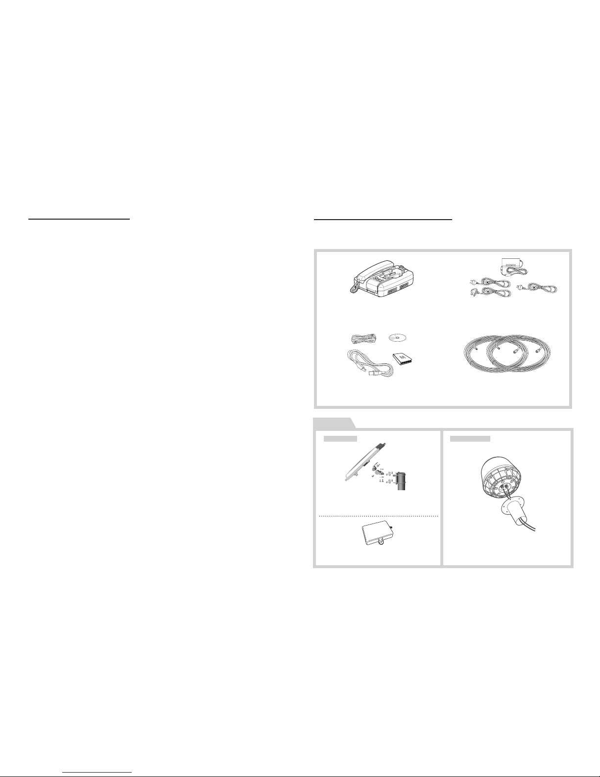
2. Package Contents
The FDU-XT PLUS package consists of the following items:
FDU-XT PLUS with an Auxiliary
Handset
Support CD, USB Cable, RJ-11 Cable,
FDU-XT PLUS User Guide
Satellite Antenna and
Mounting Adapter
GPS Antenna
Marine Antenna and
Mounting Adapter
AC/DC Power Adapter
Satellite Antenna Cable (Silver, 25m)
/ GPS Antenna Cable (Gold, 25m)
OPTION
For LAND For Marine
Page 5
FDU-XT PLUS User Guide I 03
3. Installation Instructions for Land
After unpacking, please make sure that your FDU-XT PLUS and all its
accessories are fully ready for installation. Please read the instructions
carefully. If you encounter any diculty in installation, contact your
Service Provider for assistance.
3.1. Antenna Installation
The FDU-XT PLUS antenna set consists of the following components:
1
Satellite antenna with mounting adapter.
2
Satellite antenna cable to connect the satellite antenna to
the FDU-XT PLUS (25m).
3
GPS antenna
4
GPS antenna cable to connect the GPS antenna to the
FDU-XT PLUS (25m).
3.2. Installing the Satellite Antenna
The satellite antenna is a rectangular patch antenna and is supplied
with mounting brackets.
3.2.1 How to Install the Satellite Antenna
1
Mount the antenna onto any suitable xture (mounting
pole or wall) using the provided mounting brackets and
bolts. The antenna should face the Thuraya satellite (see
3.2.2 for antenna orientation).
2
When installing the antenna, make sure the connectors are
accessible when mounted.
3
Connect the coaxial cable to the antenna connector
located at the base of the satellite antenna and tighten it
properly by turning it clockwise. Leave enough length for a
small loop and secure the rest of the cable using the cable
ties.
4
Connect the other end of the satellite antenna cable on the
reverse side of the FDU-XT PLUS to the port marked “SAT”.
Page 6

04 I
3.2.2 How to align the Satellite Antenna
Satellite based communication requires a direct line of sight to
the satellite to achieve optimal signal strength. Therefore, the
antenna must rst be mounted in a location facing the satellite
where it can then be nely adjusted for maximum reception.
The locations of the Thuraya satellites are on a geostationary
orbit (at the equator) at a more or less constant position:
Thuraya-2 satellite at 44 degrees east of the zero meridian
(approximately over Somalia)
Thuraya-3 satellite at 98.5 degrees east of the zero meridian
(approximately over Sumatra).
Antenna orientation:
Align your antenna towards the Thuraya-2 satellite if your
location is within the Thuraya-2 coverage area (Europe,
Africa, Middle East).
Align your antenna towards the Thuraya-3 satellite if your
location is within the Thuraya-3 coverage area (Asia,
Australia).
In the overlapping areas, you can approach either of the
two satellites and choose the satellite with the stronger
signal.
If you require an accurate antenna alignment, you can retrieve
precise directions from your current location to the satellite (azimuth
and elevation angle) by either of the following methods:
1
Acquire your current GPS position data with your Thuraya
satellite phone (function ‘Current position’), press Options
and send this data by SMS to the short code 1300. You will
then receive the directional data from your location to the
respective Thuraya satellite.
2
There are several independent websites where you can
retrieve directional data to a specic satellite by entering
your current location (www.dishpointer.com, www.satsig.
net or others).
Page 7

FDU-XT PLUS User Guide I 05
3.3. Installing the GPS Antenna
The GPS antenna is a smaller rectangular patch antenna.
Connect the coaxial cable to the antenna connector located at
the side of the GPS antenna and tighten it properly by turning
it clockwise.
1
Find an appropriate location to mount the antenna. Make
sure the antenna has a clear view of the sky.
2
Mark locations of the “screw holders” on the surface/rooftop
for xing the antenna.
3
Drill holes of adequate depth on the surface.
4
Keep the antenna in place so that the drilled holes and the
screw holders line up.
5
Fix the antenna securely using the screws provided.
6
Connect the other end of the GPS antenna cable on the
reverse side of the FDU-XT PLUS to the port marked "GPS".
Maintain a distance of 0.5 to 1 meter between the GPS and SAT
antenna.
Note
3.4. External Accessories
In order to use the FDU-XT PLUS, a compatible Thuraya handset
with an active SIM card is required. In addition, the following
external devices (not included) can be used with the FDU-XT
PLUS:
1
Analogue extension phone
2
Group3 fax machines
3
PC or laptop for data transfer and fax
4
External speaker or earphones
5
Bluetooth headset
The RJ-11 cable should be 2-wire inner at both ends.
Note
Page 8
06 I
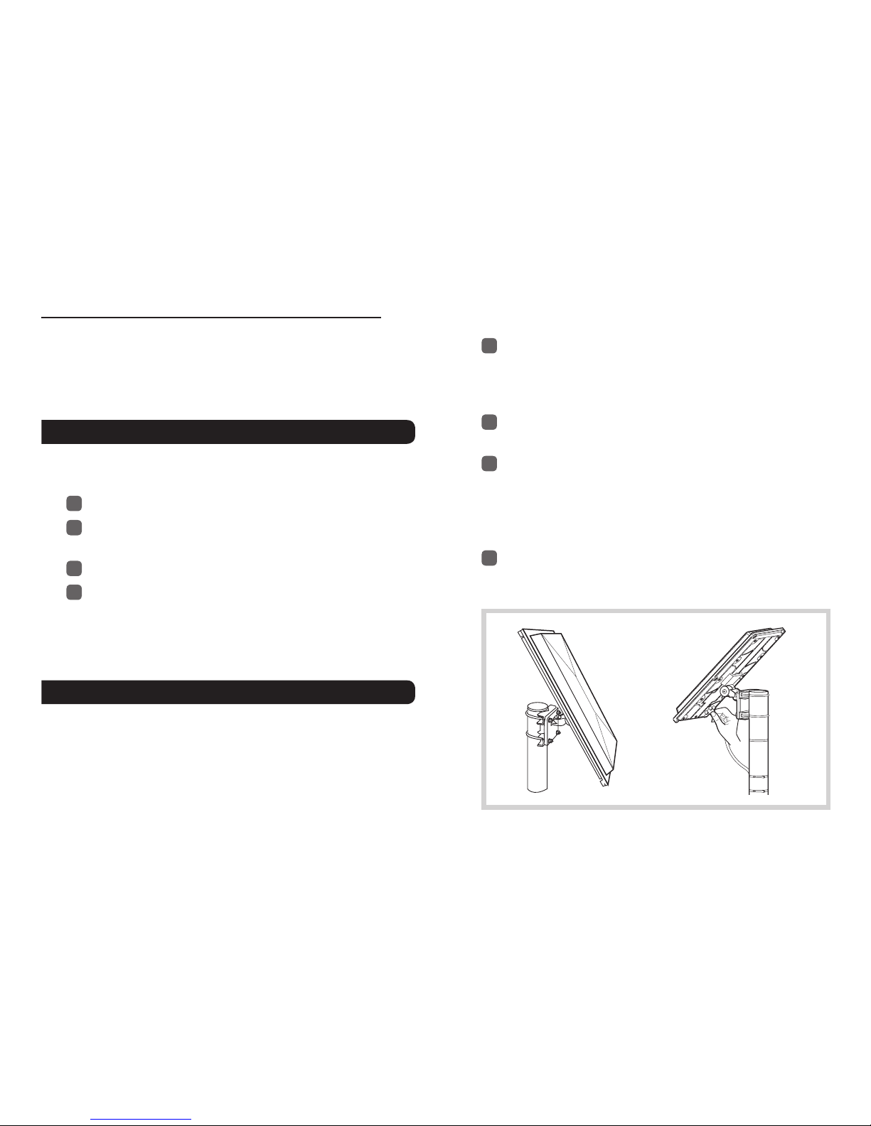
4.1. Antenna Installation
The FDU-XT Plus antenna set consists of the following components:
1
Marine antenna with mounting adapter
2
Satellite antenna cable to connect to the FDU-XT PLUS (25m)
3
GPS antenna cable to connect to the FDU-XT PLUS (25m)
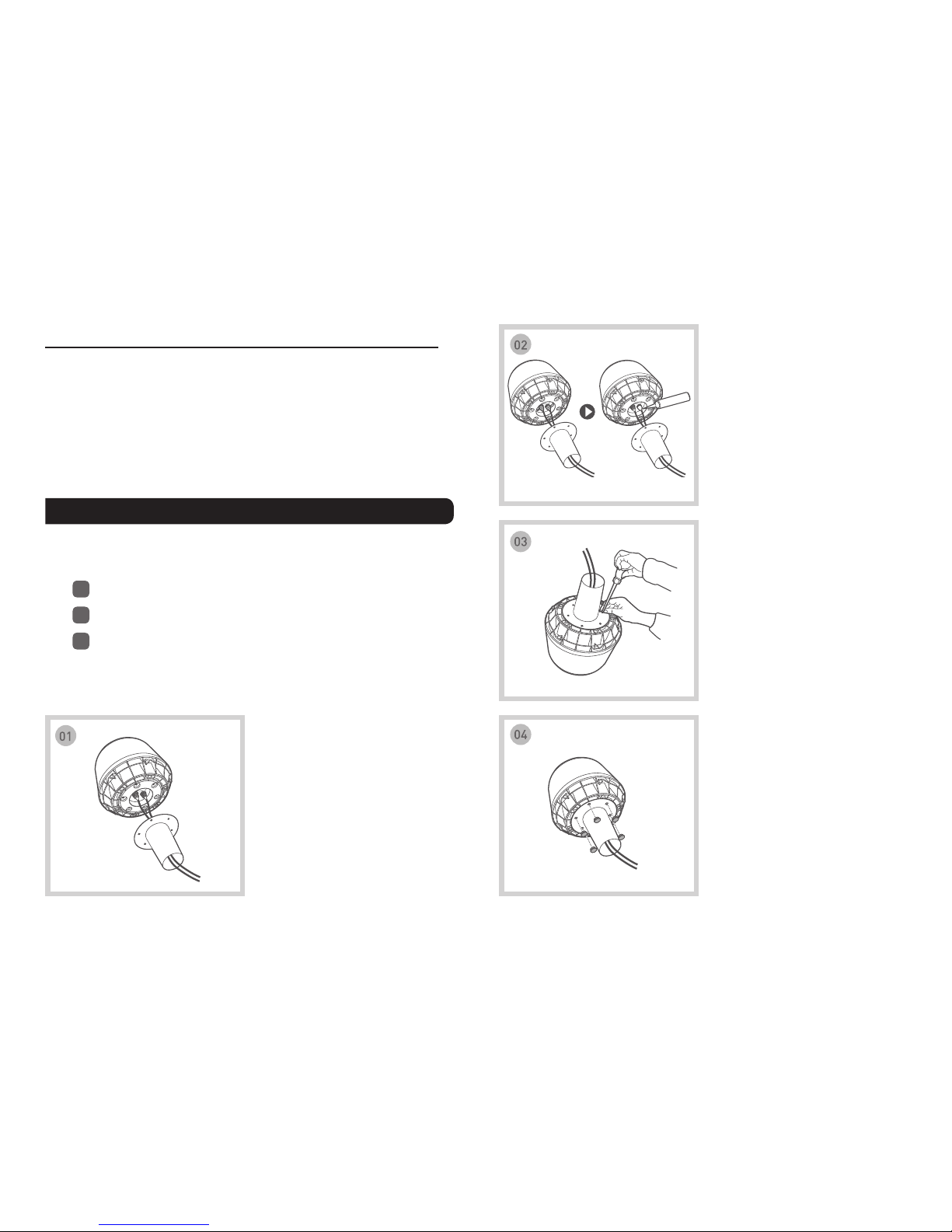
Pass the RF cable (SAT & GPS)
through the pipe and connect
the connector to the RF cable
(make sure to match the colors,
gold-to-gold and silver-to-silver).
Tighten the connector and
wrap the connected part using
magnetic coupling vinyl tape or
sealant to protect from water.
Mount the pipe to the underside
of the antenna and x securely
using bolts (M5x6).
Insert the waterproof cap into the
bolted parts.
4. Installation Instructions for Marine
After unpacking, please make sure that your FDU-XT PLUS and all its
accessories are fully ready for installation. Please read the instructions
carefully. If you encounter any diculty in installation, contact your
Service Provider for assistance.
Page 9

FDU-XT PLUS User Guide I 07
Mount the assembled antenna to
the mounting pole of your vessel
(2-inch diameter is recommended)
using the band to keep them
together. Make sure that it is tight
enough to keep it in place.
Secure the cables to the mast
using cable ties (provided at the
site).
Connect the SAT RF connector
to the port on the FDU-XT PLUS
(silver cable connector to the SAT
port).
Secure the earth wire inside the hole located on the underside
of the antenna and the other side of the wire to the mounting
pole using bolts.
Seal the heads of the bolts using sealant.
Connect the silver extension cable to the SAT port and gold extension cable to the GPS port and then connect it to the external antenna cable
connector by matching the colors.
Using extension cable
Connect the GPS RF connector
to the port on the FDU-XT PLUS
(gold cable connector to the GPS
port).
USB DTE FAX EXT SAT GPS POWER
12V
/
36V
d.c
USB DTE FAX EXT SAT GPS POWER
12V
/
36V
d.c
Page 10
08 I
USB DTE FAX EXT SAT GPS POWER
12V
/
36V
d.c
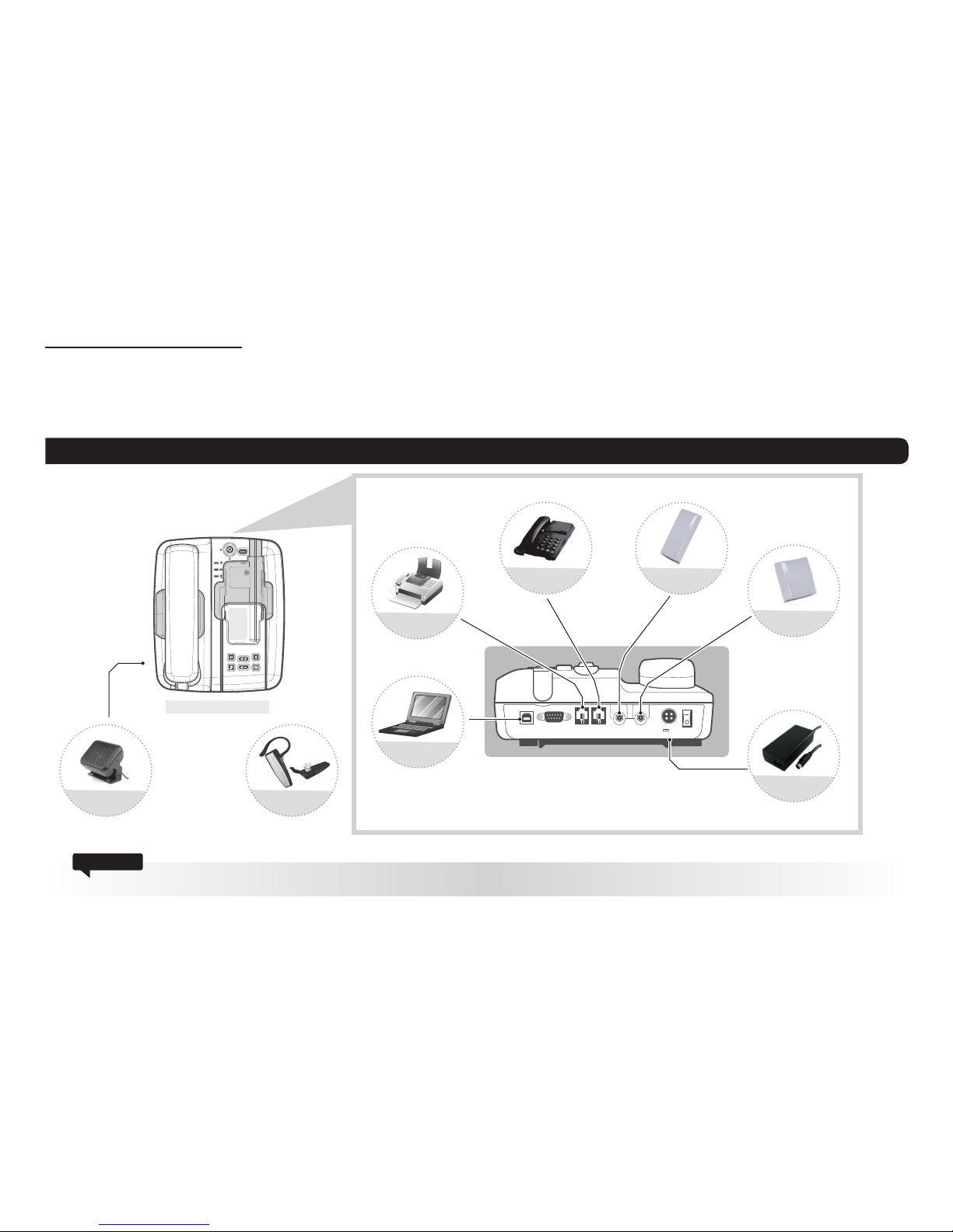
5.1. External Connections
5. Getting Started
The FDU-XT PLUS is intended to be used as a desktop or wall-mounted phone while the Thuraya handset is docked. Slots are provided at the
base of the unit to allow the FDU-XT PLUS to be hooked securely to a wall. Interfaces for connecting external equipments such as Group 3 fax
machines and PCs are provided at the reverse side of the unit.
FDU-XT PLUS
Do not connect FDU-XT PLUS with other products such as PSTN or a general telephone line.
Attention
Satellite Antenna
External Speaker
FAX
Analogue Extension
Phone
GPS Antenna
Power Adapter
(12VDC/5A)
Bluetooth Headset
PC
Page 11
FDU-XT PLUS User Guide I 09
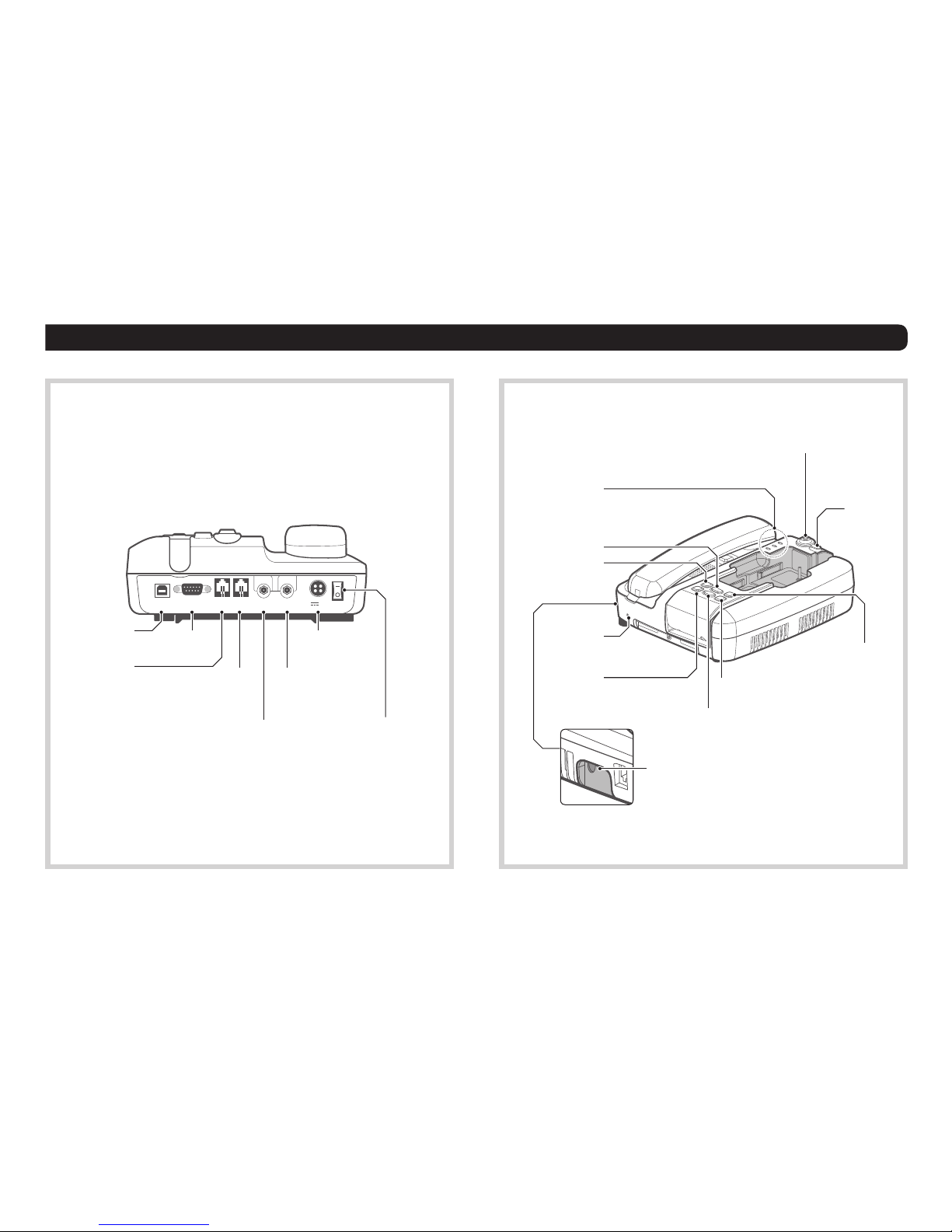
5.2. Connection Interface
USB DTE FAX EXT SAT GPS POWER
12V
/
36V
d.c
USB Port
FAX Port
DTE Port
GPS Antenna PhoneEXT Port
(for connection to
external line phones)
Satellite Antenna Port Power Switch
DC Jack
USB DTE FAX EXT SAT GPS POWER
12V
/
36V
d.c
AUX OUT
Speakerphone
Volume Up
Power LED
Charge LED
Bluetooth LED
Volume Down
Mic.
Mute
Lock handset
Eject
handset
Bluetooth scanning
Bluetooth On/O
Page 12

10 I
5.3. Using FDU-XT PLUS as a wall mounted unit
The FDU-XT PLUS can be xed on the wall by using the included
brackets. Slots for brackets are provided on the back of the FDU-XT
PLUS.
1
Find an appropriate location on the wall to mount the
FDU-XT PLUS.
2
Place the bracket on the xing location and mark the
location of the screw holes.
3
Place a suitable-length screw on the wall for mounting
FDU-XT PLUS.
4
Hook the FDU-XT PLUS to the bracket on the wall.
Page 13

FDU-XT PLUS User Guide I 11
5.4. Start using the FDU-XT PLUS
Plug in the attached power supply to an external power source and
connect the power cable to the DC IN connector on the reverse side
of the FDU-XT PLUS. Then ip the Power Switch on the reverse side
of the unit to On. The green LED will be activated to indicate that the
FDU-XT PLUS is powered on.
5.5. Connecting an extension phone to the FDU-XT
PLUS
An analogue extension phone can be connected to the FDU-XT
PLUS at the RJ-11 interface using the included RJ-11 cable.
1
Plug one end of the RJ-11 cable to the RJ-11 interface
marked “EXT” on the FDU-XT PLUS.
2
Connect the other end of the RJ-11 cable to the RJ-11
interface of the phone.
5.6. Connecting a Group 3 fax machine to the
FDU-XT PLUS
The FDU-XT PLUS can be used for sending and receiving fax messages
when connected to selected Group 3 fax machines via the RJ-11
interface.
1
Plug one end of the RJ-11 cable to the RJ-11 interface
marked “FAX” on the FDU-XT PLUS.
2
Connect the other end of the RJ-11 cable to the Group 3
Fax machine.
Contact your Service Provider to register fax services on your
SIM card.
Note
Page 14

12 I
5.7. Connecting a PC or Laptop to the FDU-XT PLUS
You can connect your FDU-XT PLUS to a PC or Laptop through the
USB or DTE interface on the reverse side of the FDU-XT PLUS.
1
Plug in one end of the USB cable (or serial cable) to the USB
port (or COM port) of your PC.
2
Connect the other end of the USB cable (or serial cable) to
the USB interface (or DTE interface) of the FDU-XT PLUS.
- To use the USB interface, please install the USB drivers for the
FDU-XT PLUS rst on your PC.
The drivers can be found on the Support CD provided with
the product.
- Contact your Service Provider to register data services on your
SIM card.
Note
5.8. Connecting an external speaker to the FDU-XT
PLUS
You can connect your FDU-XT PLUS to an external speaker via AUX
OUT port on the left side of the FDU-XT PLUS.
1
Connect a 3.5mm audio jack to the AUX OUT port on the
FDU-XT PLUS.
2
Connect the other end of the audio cable to the external
speaker.
Page 15

FDU-XT PLUS User Guide I 13
5.9. Connecting a Bluetooth headset to the FDU-XT PLUS
You can connect your Bluetooth hands-free device to the FDU-XT PLUS.
1
Hold the Bluetooth On/O ( ) button on the FDU-XT PLUS for 2 seconds to turn on the Bluetooth function.
The Bluetooth LED will blink every 2 seconds.
2
Hold the Bluetooth Scanning button on the FDU-XT PLUS for 2 seconds. The Bluetooth LED will blink every half a second and attempt
to pair with a Bluetooth device.
3
Once the device is paired with the FDU-XT PLUS, the Bluetooth LED will stay on.
4
If not connected, try again from Step 2.
Press the Bluetooth Scanning button to pair with the previously paired
device (up to 3 last paired devices).
How to clear the Bluetooth connection history
(initialize FDU-XT PLUS Bluetooth).
- Hold both Volume Down and Bluetooth Scanning buttons for 2 seconds.
- The Bluetooth HOOK and Bluetooth Scanning LED turn on for a moment and start initializing.
When paired to a Bluetooth device, incoming and outgoing calls are made
via the Bluetooth device. If not, calls are made in speakerphone mode or
using the auxiliary handset. .
To disable Bluetooth on the FDU-XT PLUS after it is turned on, hold down the
Bluetooth On/O button for 2 seconds.
(How to clear the Bluetooth connection history)
+
Useful tips:
Page 16

14 I
5.10. Docking the XT-PRO or XT
1
Before inserting the phone into the FDU-XT PLUS cradle
please remove the rubber plug of the antenna connector
on the reverse side of the phone. Then fold back the bottom
cover of the phone and attach it to the two small plastic
pins.
2
Place the Thuraya handset into the cradle with the display
facing up while attaching it to the connectors.
3
If the handset has been docked successfully, the display of
the phone will show "Fixed Adapter".
4
Ensure you have full signal strength on the display
(otherwise try to adjust the direction of the antennas).
Ensure that the dust caps on the reverse side and on the bottom
side of the Thuraya handset are removed before docking.
Note
5.11. Docking the XT-PRO DUAL
1
To dock the XT-PRO DUAL remove the 4 guide plates from
the FDU-XT PLUS as indicated in the image.
2
Pull the cup where the handset is mounted all the way down.
3
Dock the XT-PRO DUAL as explained in section 5.10.
4
Tighten the nuts located on the underside of the FDU-XT
PLUS by turning them clockwise.
Page 17

FDU-XT PLUS User Guide I 15
5.12. Undocking the handset from the FDU-XT PLUS
Your FDU-XT PLUS has a locking function to prevent unwanted
removal of the handset from the FDU-XT PLUS. The handset can only
be removed if the lock is opened. To remove the phone:
1
Allow the handset to complete all ongoing functions.
2
Unlock the handset.
3
Press the Eject button to release the handset.
LOCK
OPEN
Eject
Page 18

16 I
6. Receiving / Making Voice Calls
Before you can make and receive voice calls, please make sure the
following steps have been checked:
1
The FDU-XT PLUS is switched on.
2
The Thuraya handset is switched on.
3
The SIM card is valid and working.
4
The connections are properly set up as described in the
previous pages.
5
The Thuraya handset is properly docked in the FDU-XT
PLUS as described in the previous pages.
6
Adequate satellite and GPS signal strength is available (see
display of the handset).
6.1. Receiving Voice Calls
Incoming calls are indicated by:
1
Ringing tone from the speakerphone (optionally from the
extension phone if attached or from the Bluetooth headset
if connected)
2
Flashing of the speakerphone LED (and optionally ashing
of the Bluetooth LED if Bluetooth headset is connected).
You can accept incoming calls trough the speakerphone,
auxiliary handset, extension phone or Bluetooth headset.
Accepting Calls from the Auxiliary Handset
Pick up the Auxiliary handset.
Accepting Calls from the Speakerphone
Press the Speakerphone button.
Accepting Calls from Extension Phone
Pick up the handset of the Extension phone.
Accepting Calls from Bluetooth headset
Press the Bluetooth On/O button or the call button of the
Bluetooth headset.
Page 19

FDU-XT PLUS User Guide I 17
6.2. Making Calls
Calling from the Speakerphone :
1. Dial the destination number using the keypad of the
Thuraya handset.
2. Press the Call button ( ) on the Thuraya handset.
Calling from the Auxiliary Handset
Method 1
1. Pick up the auxiliary handset.
2. Wait for the dial tone.
3. Dial the destination number using the Thuraya handset
keypad.
4. Press call button on Thuraya handset.
Method 2
1. Dial the destination number using Thuraya handset keypad
while the auxiliary handset is on the cradle.
2. Pick up the auxiliary handset.
Calling from the Extension Phone
1. Pick up the handset of the Extension phone.
2. Wait for the dial tone.
3. Dial the destination number on the Extension phone
keypad.
4. Press (*or #) on the Extension phone keypad after entering
the numbers.
Calling from the Bluetooth headset
1. Check if the Bluetooth headset is connected to the FDU-XT
PLUS
2. Dial the destination number using the Thuraya handset
keypad.
3. Press call button on Thuraya handset.
Page 20

18 I
Ending a Speakerphone Call
Press the Speakerphone button.
Ending calls with the auxiliary handset
Hang up the auxiliary handset
Ending calls with an extension phone
Hang up the extension phone
Ending a Bluetooth Call
Press the Bluetooth On/O button or the call button of the
Bluetooth headset
6.3. Ending Calls 6.4. Auxiliary handset
Speakerphone to Auxiliary Handset
1. Pick up the auxiliary handset during the call. The call will
be routed to the auxiliary handset.
Auxiliary Handset to Speakerphone
1. Press the speakerphone button on the FDU-XT PLUS
during a call.
2. Ensure the speakerphone LED is blinking, afterwards hang
up the auxiliary handset.
Speakerphone to Extension Phone
1. Pick up the Extension phone handset.
Extension Phone to Speakerphone
1. Press the speakerphone button on the FDU-XT PLUS
during a call.
2. Ensure the speakerphone LED is blinking, afterwards hang
up the extension phone.
Page 21

FDU-XT PLUS User Guide I 19
Bluetooth to Auxiliary Handset
1. Pick up the Auxiliary handset during the call. The call will
be routed to the auxiliary handset.
Auxiliary Handset to Bluetooth
1. Press the Bluetooth On/O button on the FDU-XT PLUS
during a call.
2. Ensure the Bluetooth On/O button LED is blinking,
afterwards hand up the auxiliary handset.
Speakerphone to Bluetooth
1. Press the Bluetooth On/O button on the FDU-XT PLUS
during a call.
Bluetooth to Speakerphone
1. Press the Speakerphone button on the FDU-XT PLUS
during a call.
6.5. Volume Control
You can adjust the volume of the speakerphone, auxiliary handset
and ringtone using the Volume Up and Volume Down button on the
FDU-XT PLUS.
Adjusting auxiliary handset volume
1. Pick up the auxiliary handset.
2. Press the Volume Up/Volume Down button to increase/
decrease the auxiliary handset volume as required.
Adjusting speakerphone volume
1. Switch the speakerphone on.
2. Press the Volume Up/Volume Down button to increase/
decrease the speakerphone volume as required.
Adjusting ringtone volume
1. Select the ringtone of your Thuraya handset from the
handset menu.
2. Switch the speakerphone on.
3. Press the Volume Up/Volume Down buttons to increase/
decrease the ringtone volume.
Page 22

20 I
To Un-mute the call
Press the Mute button again.
6.6. Muting the microphone in speakerphone mode
You can mute the microphone while in speakerphone mode by
pressing the mute button. You will then be able to hear the caller at
the other end but the other party will not be able to hear you.
If you pick up the auxiliary handset now, the call will be automat-
ically unmuted and routed to the auxiliary handset.
Note
Page 23

FDU-XT PLUS User Guide I 21
7.
Sending / Receiving Fax Messages
Your FDU-XT PLUS supports sending and receiving fax messages
either via a connected Group3 fax machine or a connected
PC/Laptop with fax software.
7.1. Sending fax messages with a fax machine
1
Dock your Thuraya handset into the FDU-XT PLUS.
2
Switch on the Group3 fax machine connected via the RJ-11
interface.
3
Switch on the FDU-XT PLUS.
4
Place the fax sheet in the fax machine and dial the
destination number followed by * or #.
5
Press the start button on the fax machine.
1
Dock your Thuraya handset into the FDU-XT PLUS.
2
Switch on the FDU-XT PLUS.
3
Switch on the Group3 fax machine that is connected via the
RJ-11 interface.
7.2. Receiving fax messages with a fax machine
A ringtone in the fax machine indicates an incoming fax call.
Note
Page 24

22 I
1
Dock your Thuraya handset into the FDU-XT PLUS.
2
Connect the PC to the USB or DTE serial interface of the
FDU-XT PLUS.
3
Switch on the FDU-XT PLUS.
4
Start the PC fax software.
5
While conguring the fax software, select 'ne' as resolution.
6
Enter the destination number.
7
Select the document to be sent.
8
Use the respective start function of the fax software to start
transmitting the fax.
7.3. Sending fax messages with a PC/Laptop
While sending a fax through PC connected through the USB or
DTE interface, the fax software should be congured in the class
2.0 mode. When sending a fax through Venta Fax or Hot Fax, select
“Thuraya Mobile Phone” or “Standard 56000 Modem” as a modem.
Note
1
Dock your Thuraya handset into the FDU-XT PLUS.
2
Connect the PC to the USB or DTE serial interface of the
FDU-XT PLUS.
3
Switch on the FDU-XT PLUS.
4
Start the PC fax software.
5
If there is no Group3 fax machine connected to the FDU-XT
PLUS, all incoming fax messages will be received by the
connected PC/Laptop.
7.4. Receiving fax messages with a PC/Laptop
Page 25

FDU-XT PLUS User Guide I 23
8. Receiving / Sending Data
You can use your FDU-XT PLUS to receive and make
circuit-switched data calls through a PC connected through the
USB or DTE interface. To receive/make data calls via a PC,
appropriate data communication software needs to be installed
on the PC.
The baud rate of the PC data communication software should be
set at 115200bps.
Note
1
Dock your Thuraya handset into the FDU-XT PLUS.
2
Connect the PC to the USB or DTE serial interface of the
FDU-XT PLUS.
3
Switch on the FDU-XT PLUS.
4
Start the data communication software of your PC.
5
Enter the destination number.
6
Select the data le to be sent.
7
Use the respective start function of the data communication
software to start transmitting the le.
8.1. Sending data from a PC/Laptop
1
Dock your Thuraya handset into the FDU-XT PLUS.
2
Connect the PC to the USB or DTE serial interface of the
FDU-XT PLUS.
3
Switch on the FDU-XT PLUS.
4
Start the data communication software on the PC/Laptop.
5
You will hear a special signal on the docked Thuraya handset
when a data call is arriving.
8.2. Receiving data
Page 26

24 I
9. GmPRS Connection
By connecting your FDU-XT PLUS to a computer you can use
satellite data services via the FDU-XT PLUS.
Equipment & software requirements:
FDU-XT PLUS
FDU-XT PLUS drivers installation le (included in provided CD)
USB data cable (included in your FDU-XT PLUS packaging)
PC with Windows 10, Windows 8/8.1, Windows 7 or Windows Vista
Run the drivers installation le – the drivers will be installed.
Use data services by setting up your phone docked in FDU-XT
PLUS as a data modem. For satellite data, choose either GmPRS
(up to 60/15 kbps download/upload) or Circuit Switched Data (9.6
kbps):
Step 1
Connect your FDU-XT PLUS with the PC/laptop and set the phone
up as a data modem. Connect via the included USB data cable for
satellite data:
Select Start > Settings > Control Panel > System > Device
Manager.
Check the USB serial port number for FDU-XT PLUS (e.g. COM40)
with the newly created USB serial port when the USB cable is
connected.
Select Start > Settings > Control Panel > Phone and Modem.
Select the Modems tab and press Add.
Check the box of “Don’t detect my modem; I will select it from a
list.” and press Next.
Select and press Standard 56000 bps Modem and press Next.
Select the USB serial port that you previously checked above
and press Next.
When the modem installation is completed, press Finish.
Right click on “Standard 56000bps Modem” which is newrly
created in the Modems window.
Select “Properties” and make sure that “Modem tap >
Maximum Port Speed” is set to “115200”.
Step 2
Create a dial-up connection and in the dial-up phone number
eld, enter the access number *99# for GmPRS or 1722 for Circuit
Switched Data:
Drivers Installation
Data Services via the FDU-XT PLUS
Page 27

FDU-XT PLUS User Guide I 25
For Windows Vista & Windows 7:
Select Start > Settings > Control Panel > Network and Sharing
Center.
Select and press Set up a new connection or network.
Select and press Set up dial-up connection and then Next.
Enter *99# or 1722 on the Dial-up phone number eld.
(Optionally you can enter user name and password).
Enter connection name and press Connect.
Use the Internet via the newly created dial-up connection.
Select and press Set up a new connection or network.
Select and press Connect to the Internet and then Next.
Select and press Set up a new connection anyway.
Select and press No, create a new connection then Next.
Select and press Dial-up (Connect using a dial-up modem or ISDN)
Enter *99# or 1722 on the Dial-up phone number eld.
(Optionally you can enter user name and password)
Enter connection name and press Connect.
Use the Internet via the newly created dial-up connection
For Windows 10:
Select Start > Control Panel > Network and Internet >
Network and Sharing Center.
Access Point Name (APN)
GmPRS settings
There are 3 Thuraya APNs available to use data in satellite mode, to
change the default setting:
- On the Thuraya XT-PRO DUAL, go to Menu > Settings > Data
settings > GmPRS settings
- On the Thuraya XT and XT-PRO, go to Menu > Settings > GmPRS
> APN
GET (default, no compression)
GETLC (low compression, images will be compressed)
GETHC (high compression, images will not be downloaded)
GETLC and GETHC are designed to compress all http trac that is
routed through them. Any emails and apps that do not use http
will be delivered uncompressed.
For Windows 8/8.1:
Select Start > Settings > Control Panel > Network and Sharing
Center.
Select and press Set up a new connection or network.
Select and press Set up dial-up connection and then Next.
Select and press Connect to the network and then Next.
Select and press No, create a new connection and then Next.
Select and press Dial-up connection and then Next.
Enter *99# or 1722 on the Dial-up phone number eld.
(Optionally you can enter user name and password).
Enter connection name and press Connect.
Use the Internet via the newly created dial-up connection.
Page 28

26 I
10. Extension Phone Locking
If you use an external extension phone in combination with the
FDU-XT PLUS, you can protect the usage of the extension phone with
a PIN code. After activating the PIN locking function, a user will have
to enter the correct PIN in order to make a phone call from the extension
phone.
The PIN code of the FDU-XT PLUS is per default set to "0000".
If the extension phone locking is enabled use the following procedure
to make a call: on the extension phone enter the PIN code
telephone number or # (e.g.: 0000123456789)
1
Connect the extension phone to the RJ-11 interface marked
"EXT" on the reverse side of the FDU-XT PLUS.
2
Press PIN (e.g.: 0000)
3
Hang up the phone after hearing the beep which indicates
the activation of the PIN code.
1
Connect the extension phone to the RJ-11 interface marked
"EXT" on the reverse side of the FDU-XT PLUS.
2
Press # PIN (e.g.: #0000)
3
Hang up the phone after hearing the beep which indicates
the deactivation of the PIN code.
10.1. Enable extension phone locking:
10.2. Disable extension phone locking:
Page 29

FDU-XT PLUS User Guide I 27
1
Connect the extension phone to the RJ-11 interface marked
"EXT" on the reverse side of the FDU-XT PLUS.
2
Press # Old PIN (4 digits) New PIN (4 digits)
(e.g.: #00001234)
3
Hang up the phone after hearing the beep which indicates
the conrmation of the PIN change.
10.3. How to change the PIN code
Please make sure you do not forget the new PIN code, otherwise
you need to bring the FDU-XT PLUS to the Service Center in order to
reset the unit.
11. SOS Calling
How to make an SOS call:
1
This feature is only compatible with the XT-PRO DUAL and
XT-PRO.
2
Simultaneously hold the Mute and Bluetooth Scanning
buttons for 3 seconds.
3
Mute and Bluetooth Scanning button will blink and SOS
call is enabled.
+
Page 30

28 I
12. Troubleshooting
Your FDU-XT PLUS does not contain consumer serviceable components.
You are advised not to carry out any kind of troubleshooting. In
case you face any problems, contact the nearest service center. Only
authorized service personnel can repair the equipment.
Use only the antennas and cables that have been provided with the
unit or that have been specically designed for your FDU-XT PLUS.
Unauthorized antennas, cables and cable length modication or
attachments could damage the FDU-XT PLUS and may violate the
relevant regulations, causing loss of performance and radio frequency
(RF) energy above the recommended limits. If your FDU-XT PLUS’s
antenna gets damaged, please take it to an authorized service center.
Do not place the FDU-XT PLUS in a wet area.
Do not expose the FDU-XT PLUS to temperatures higher
than +55°C Celsius or less than 0°C Celsius.
Do not expose the FDU-XT PLUS to moisture, dust etc.
Do not expose the FDU-XT PLUS to direct sunlight.
Do not disassemble the FDU-XT PLUS; this will void your
warranty.
Do not store it in hot areas. High temperatures can shorten
the life of electronic devices, damage batteries, and warp
or melt certain plastics.
Do not drop, apply pressure or shake it. Rough handling
can break internal circuit boards.
Do not use chemicals, cleaning solvents, or strong
detergents to clean it. Wipe it smoothly with a soft cloth.
Do not paint it. Paint can clog the device’s moving parts
and prevent proper operation.
If the FDU-XT PLUS, the phone, battery, charger or any accessory
does not function properly, take it to your nearest authorized service
center. The personnel there will assist you, and if necessary, arrange
for service.
Page 31

FDU-XT PLUS User Guide I 29
There is not enough satellite signal strength
(minimum of two bars should be shown on the handset display, otherwise adjust the antenna).
Thuraya handset is not properly docked.
Thuraya handset is switched o.
FDU-XT PLUS is not switched on.
Connections are not proper and rm.
Common Problems
Problem Solution
Unable to make/receive calls
Check if PIN locking is enabled and if PIN code is correct.
Check if the RJ-11 cable is properly connected (when using an extension phone).
If the extension phone is not working, try to use the auxiliary handset. If you are able to make/receive calls with the
auxiliary handset, please check the functioning of the extension phone.
The auxiliary handset
is not working
Check whether the auxiliary handset is connected properly.
Speakerphone not
working
Make sure that the speakerphone is on.
Select appropriate volume level.
Unable to
send/receive fax
through RJ-11
Check if PIN locking is enabled and if PIN code is correct.
Check if the RJ-11 cable is properly connected.
Check if the fax machine is switched on and is functional.
Make sure that the Group3 fax machine is in auto response mode.
Check if the SAT signal level on the Thuraya handset is adequate.
Please note that not all Group3 fax machines are able to handle mobile transmission.
Unable to send/receive fax
through PC
Make sure that you have appropriate PC Fax software installed in your system for sending/receiving fax through PC.
Check parameters on the fax software that you are using.
Unable to pair a device
Check if Bluetooth of the FDU-XT PLUS is powered on.
Initialize FDU-XT PLUS Bluetooth.
Page 32

30 I
LED Status Indication
The green Power LED ( ) is on. FDU-XT PLUS is switched on
The green Battery LED ( ) is on. Handset battery is fully charged
The red Battery LED ( ) is on. Handset battery is charging
The white Speakerphone LED is ashing.
(The white Bluetooth LED is also ashing if Bluetooth connected)
Incoming call
The white LED on the Speakerphone button ( ) is on. Speakerphone is on
The white LED on the Bluetooth On/O button ( ) is on. Bluetooth call is on
The white LED on the Mute button ( ) is on. Microphone is muted
The blue Bluetooth LED ( ) is ashing (2 seconds intervals) Bluetooth standby
The blue Bluetooth LED ( ) is ashing (0.5 seconds intervals) Bluetooth is scanning
The blue Bluetooth LED ( ) is on. Bluetooth is connected
13. LED Indications
Page 33

FDU-XT PLUS User Guide I 31
14. Warranty
Limited Warranty
FDU-XT PLUS
This Limited Warranty is provided to the original purchaser of FDU-XT PLUS. This Limited Warranty is non-transferable in nature.
Warranty Coverage and Service
APSI warrants all new FDU-XT PLUS handsets to be free from defects in
material and workmanship under normal use and wear for a period of
one year (1 year) from the date of purchase. If under normal use the product becomes defective in materials or workmanship and is returned to a
APSI Authorized Service Center during the warranty period, the product
will be repaired or replaced at no charge to the purchaser. The purchaser
shall be required to provide reasonable proof of the date of purchase of
the product.
Repair or replacement of the Product is subject to APSI System Design’s
sole and exclusive option. Reconditioned replacement components,
parts, units, or materials may be used if the Product is repaired or
replaced. Cost incurred in the removal, de-installation or reinstallation of
the Product are not covered.
This Limited Warranty will be void in its entirety if the Product is serviced
by anyone other than APSI or a APSI Authorized Service Center.
The User’s sole and exclusive solution will be repair or replacement of
the product. APSI neither assumes nor authorizes any Authorized Service
Center or any other person or entity to assume any other obligation or
liability beyond that which has been specied in this Limited Warranty.
Limitation of Liability
All liability and obligations of APSI under this Limited Warranty shall
terminate on the completion of the warranty period of one year, calculated
from the date of purchase of the product by the original purchaser. The
purchaser shall ll in the warranty card attached in the User’s manual and
get it duly stamped and signed by the Dealer as proof of purchase.
This limited warranty sets forth the entire responsibility of APSI with
respect to the product. There are no other liabilities of APSI arising from
the sale of the Product whether based on warranty, contract, negligence
or any other theories of liability.
This Warranty does not cover the following
APSI will not be responsible for products or accessories not manufactured
or provided by APSI. APSI will not take responsibility for the failures caused
by misuse, accident, alteration or neglect, removal or repair, neglect or
failure to follow instructions as to installation and maintenance, re, ood
or other natural calamities. APSI will not guarantee the performance of the
product when used in combination with other non authorized products
or equipment.
Page 34

32 I
Item Standard
Dimensions 198(W) x 235(H) x 86(H)
Interfaces
3 x RJ-11:
- External telephone connection (voice call)
- External G3 fax connection (fax call)
- Auxiliary handset connection (voice call)
1 x RS-232 serial connection
1 x USB PC connection
2 x SMA connections:
- Satellite antenna connection
- GPS antenna connection
1 x SPK (AUX OUT) connection
Power
- Universal AC/DC power supply: 110 - 240V
- Input power DC 12V ~ 36V
15. Specications
Page 35

Page 36

www.thuraya.com
Thuraya Telecommunications Company
Emall: customer.care@thuraya.com
 Loading...