

Page 1

Page 2

ㅣ
32
ㅣ
5.3. Ending Calls 15
5.4. Transferring 51sllaC
5.5. Volume 61lortnoC
5.6. Muting the microphone in speakerphone mode 16
6. Sending and receving fax 71segassem
6.1. Sending fax messages with a fax 71enihcam
6.2. Receiving fax messages with a fax 71enihcam
6.3. Sending fax messages with a 81potpaL/CP
6.4. Receiving fax messages with a 81potpaL/CP
7. Receiving/Sending Data 18
7.1. Sending data from a 91potpaL/CP
7.2. Receiving 91atad
8. GmPRS 91noitcennoC
9. Extension phone 32gnikcol
9.1. Enable extension phone 32gnikcol
9.2. Disable extension phone 32gnikcol
9.3. How to change the PIN 32edoc
10. 42gnitoohselbuorT
11. LED Indications 26
12. 62ytnarraW
13. Specifications
28
1. Introduction 4
2.
Package Contents 4
3. Installation Instructions 5
3.1. Antenna Installation 5
3.2. Installing theSatellite 5annetnA
3.2.1. How to install the Satellite 5annetnA
3.2.2. How to align the Satellite 6annetnA
3.3. Installing the GPS 8annetnA
3.4. External Accessories 8
4. Getting Started 8
4.1. External 9snoitcennoC
4.2. Connection Interface 10
4.3. Using FDU-XT as a wall mounted 11tinu
4.4. Start using the 11TX-UDF
4.5. Connecting an extension phone the FDU-XT 11
4.6. Connecting a Group 3 fax machine to the FDU-XT 12
4.7. Connecting a PC to Laptop to the FDU-XT 12
4.8. Docking a Thuraya satellite 21enohp
4.9. Undocking the handset from the FDU-XT 13
5. Receiving/Making Voice Calls 14
5.1. Receiving Voice Calls 14
5.2. Making Calls 15
Table of Contents
Table of Contents
Page 3
4
ㅣ ㅣ
5
1. Introduction
The FDU-XT (Fixed Docking Unit) is a home/office docking adapter that allows you
to use Thuraya satellite services in indoor environments. It provides additional
flexibility and convenience when using Thuraya XT-series handsets.
In addition, FDU-XT and its accessories are designed to meet Thuraya’s
specifications and quality standards.
This indoor enabler enhances the capabilities of your Thuraya handset to meet
your communication requirements, both in the home and in the office.
When a Thuraya handset is used with FDU-XT, the handset becomes an indoor
communication center providing voice, fax and data communication.
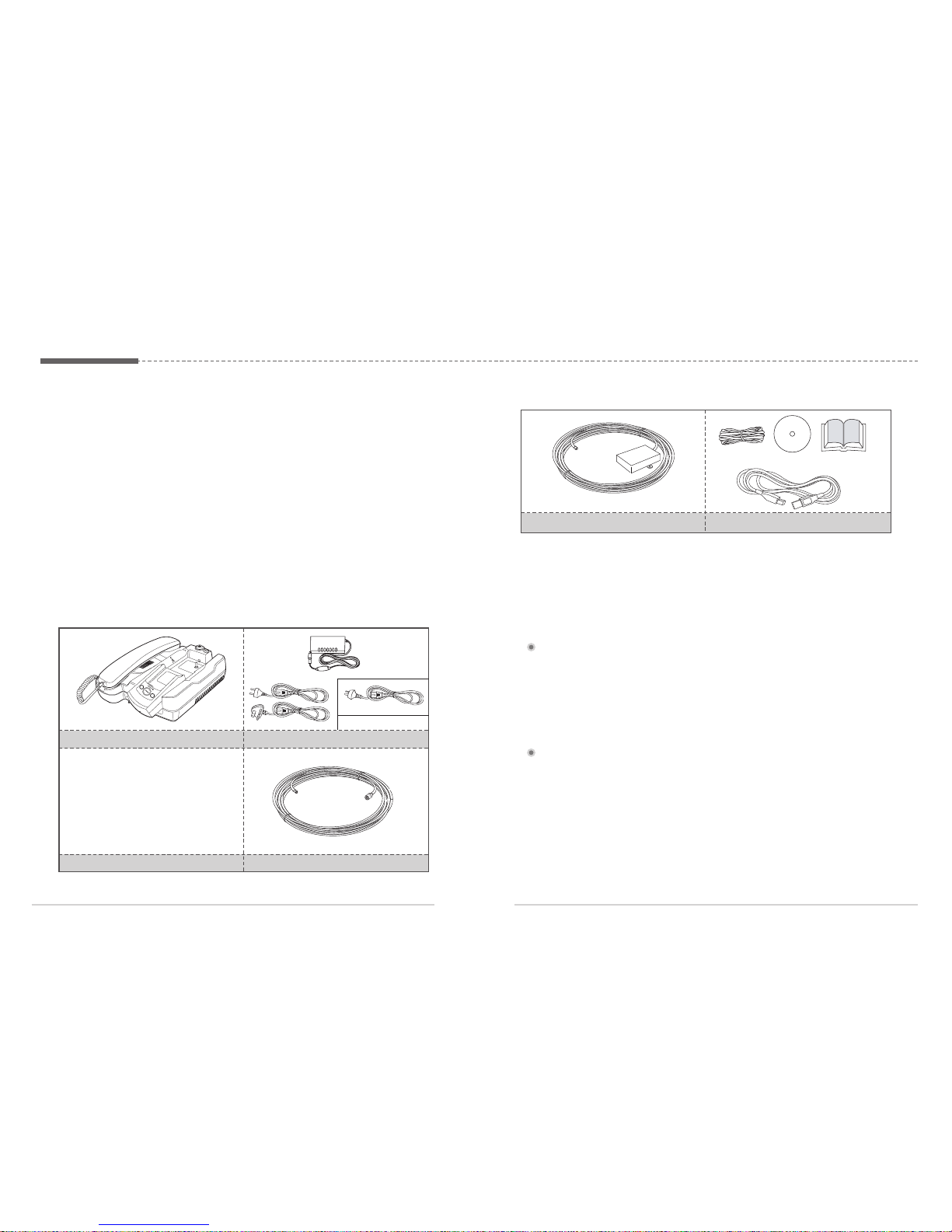
2. Package Contents
The FDU-XT package consists of the following items:
FDU-XT with an Auxiliary Handset AC/DC Power Adapter
AUS (Optional)
GPS Antenna with Cable (25m)
Support CD, USB Cable, RJ-11 Cable,
FDU-XT User’s Manual
3. Installation Instructions
After unpacking, please make sure that your FDU-XT and all its accessories are
fully ready for installation. Please read the instructions carefully. If you encounter
any difficulty in installation, contact your Service Provider for assistance.
3.1. Antenna Installation
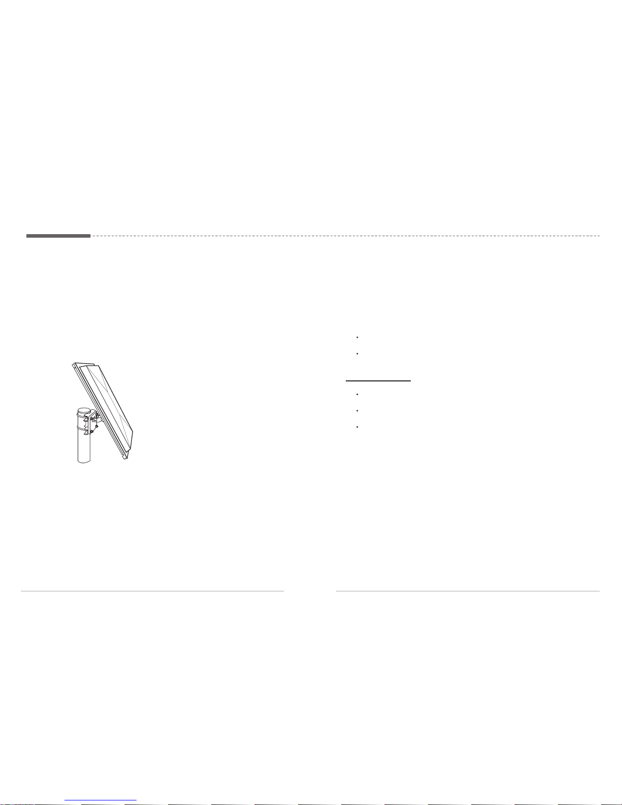
The FDU-XT antenna set consists of the following components:
1. Satellite antenna with mounting adapter.
2. Satellite antenna cable to connect the satellite antenna to the FDU-XT (25m).
3. GPS antenna with attached coaxial cable to connect to the FDU-XT (25m).
Satellite Antenna and Mounting Adapter Satellite Antenna Cable (25m)
3.2. Installing the Satellite Antenna
The satellite antenna is a rectangular patch antenna and is supplied with mounting
brackets.
3.2.1. How to install the Satellite Antenna
1. Mount the antenna onto any suitable fixture (mounting pole or wall) using
the provided mounting brackets and bolts. The antenna should face the
Thuraya satellite (see 3.2.2 for antenna orientation).
Page 4
ㅣ
76
ㅣ
2. When installing the antenna, make sure the connectors are accessible
when mounted.
3. Connect the coaxial cable to the antenna connector located at the base of
the satellite antenna and tighten it properly by turning it clockwise. Leave
enough length for a small loop and secure the rest of the cable using the
cable ties.
4. Connect the other end of the satellite antenna cable to the reverse side of
the FDU-XT marked “SAT”.
3.2.2. How to align the Satellite Antenna
Satellite based communication requires a direct line of sight to the satellite to
achieve optimal signal strength. Therefore, the antenna must first be mounted in
a location facing the satellite where it can then be finely adjusted for maximum
reception.
The locations of the Thuraya satellites are on a geostationary orbit (at the
equator) at a more or less constant position:
Thuraya-2 satellite at 44 degrees east of the zero meridian (approximately
over Somalia)
Thuraya-3 satellite at 98.5 degrees east of the zero meridian(approximately
over Sumatra)cable ties.
Antenna orientation:
Align your antenna towards the Thuraya-2 satellite if your location is within
the Thuraya-2 coverage area (Europe, Africa, Middle East).
Align your antenna towards the Thuraya-3 satellite if your location is within
the Thuraya-3 coverage area (Asia, Australia).
In the overlapping areas, you can approach either of the two satellites and
choose the satellite with the stronger signal.
If you require an accurate antenna alignment, you can retrieve precise directions
from your current location to the satellite (azimuth and elevation angle) by either
of the following methods:
1. Acquire your current GPS position data with your Thuraya satellite phone
(function ‘Current position’), press Option and send this data by SMS to the
short code 1300. You will then receive the directional data from your
location to the respective Thuraya satellite.
2. There are several independent websites where you can retrieve directional
data to a specific satellite by entering your current location
(www.dishpointer.com, www.satsig.net or others).
Page 5
ㅣ
98
ㅣ
3.3. Installing the GPS Antenna
The GPS antenna comes with an attached coaxial cable to connect to the
FDU-XT unit.
1. Find an appropriate location to mount the antenna.
Make sure the antenna has a clear view of the sky.
2. Mark locations of the “screw holders” on the surface/rooftop for fixing the
antenna.
3. Drill holes of adequate depth on the surface.
4. Keep the antenna in place so that the drilled holes and the screw holders
line up.
5. Fix the antenna securely using the screws provided.
6. Connect the free end of the attached cable to the GPS antenna connector
marked “GPS” on the reverse side of the FDU-XT.
Maintain a distance of 0.5 to 1 meter between the GPS and SAT antenna.
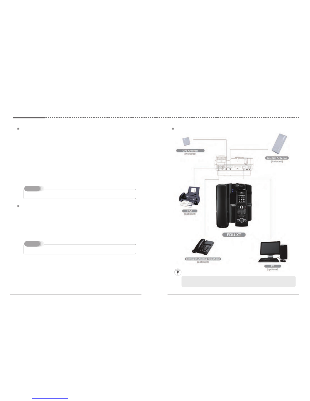
3.4. External Accessories
In order to use the FDU-XT, a Thuraya XT-series satellite phone with an active
SIM-card is required. In addition the following external devices can be used with
the FDU-XT:
1. Analogue extension phone
2. Selected Group3 fax machines with fax software for PC-fax
3. PC or laptop for data transfer and PC-fax
Note
The RJ-11 cable should be 2-wire inner at both ends.
Note
4. Getting Started
The FDU-XT is intended to be used as a desktop or wall-mounted phone while
the Thuraya handset is docked. Slots are provided at the base of the unit to allow
The FDU-XT to be hooked securely to a wall. Interfaces for connecting external
equipments such as Group 3 fax machines and PCs are provided at the back
side of the unit.
1. Do not connect FDU-XT with other products such as PSTN or a general telephone line.
Attention
4.1. External Connections
Page 6

ㅣ
1110
ㅣ
4.2. Connection Interface
4.3. Using FDU-XT as a wall mounted unit
The FDU-XT can be fixed on the wall by using the included brackets. Slots for
brackets are provided on the back of the FDU-XT.
1. Find an appropriate location on the wall to mount the FDU-XT.
2. Place the bracket on the fixing location and mark the location of the screw
holes.
3. Place a suitable-length screw on the wall for mounting FDU-XT.
4. Change the direction of Handset holder to a wall-mounted unit.
5. Hook theFDU-XT to the bracket on the wall.
This product contains an air ventilation fan. To ensure the fan’s normal operation, do not
install the unit in a dusty area.
Note
4.4. Start using the FDU-XT
Plug in the attached power supply to an external power source and connect the
power cable to the DC IN connector on the reverse side of the FDU-XT. Afterwards
you are ready to switch on the FDU-XT on the reverse side of the unit. The blue
power LED will be activated to indicate the power status of the FDU-XT.
4.5. Connecting an extension phone to the FDU-XT
An alogue extension phone can be connected to the FDU-XT at the RJ-11
interface using the included RJ-11 cable.
Page 7

ㅣ
1312
ㅣ
To use the USB interface, please install the USB drivers for the FDU-XT first on your PC. The
drivers can be found on the Support CD provided with the product.
Contact your Service Provider to register data services on your SIM card.
Note
4.6. Connecting a Group 3 fax machine to the FDU-XT
The FDU-XT can be used for sending and receiving fax messages when
connected to selected Group 3 fax machines via RJ-11 interface.
1. Plug one end of the RJ-11 cable to the RJ-11 interface marked “FAX” on
the FDU-XT.
2. Connect the other end of the RJ-11 cable to the Group 3 Fax machine.
4.7. Connecting a PC or Laptop to the FDU-XT
You can connect your FDU-XT to a PC or Laptop through the USB or DTE interface
on the reverse side of the FDU-XT.
1. Plug in one end of the USB cable (or Serial cable) to the USB port
(or COM port) of your PC.
2. Connect the other end of the USB cable (or Serial cable) to the USB interface
(or DTE interface) of the FDU-XT.
1. Plug one end of the RJ-11 cable to the RJ-11 interface marked “EXT” on
the FDU-XT.
2. Connect the other end of the RJ-11 cable to the RJ-11 interface of the phone.
Contact your Service Provider to register fax services on your SIM card.
Note
Ensure that the dust caps on the reverse side and on the bottom side of the Thuraya handset
are removed before docking.
Note
4.8. Docking a Thuraya satellite phone
1. Before inserting the phone into the FDU-XT cradle please remove the rubber
plugs of the antenna connector on the reverse side of the phone. After that
fold back the bottom cover of the phone and attach it to the two small plastic
pins.
2. Place the Thuraya satellite phone into the cradle with the display facing up
while attaching it to the connectors.
3. If the handset has been docked successfully, the display of the phone will
show "Fixed Adapter".
4. Ensure you have full signal strength on the display (otherwise try to adjust the
direction of the antennas).
4.9. Undocking the handset from the FDU-XT
Your FDU-XT has a locking function to prevent unwanted removing of the handset
from the FDU-XT. The handset can only be removed if the lock is opened. To
remove the phone after unlocking:
1. Allow the handset to complete all ongoing functions.
2. Press the Eject button to release the handset
4.5. Connecting an extension phone to the FDU-XT
An alogue extension phone can be connected to the FDU-XT at the RJ-11
interface using the included RJ-11 cable.
Page 8

ㅣ
1514
ㅣ
5.1. Receiving Voice Calls
Incoming calls are indicated by:
1. Ringing tone from the speakerphone (and optionally from the extension
phone if attached)
2. Flashing of the speakerphone LED.
You can accept incoming calls trough the speakerphone, auxiliary handset, or
extension phone.
The speakerphone LED will remain ON if the call was not answered.
Note
5. Receiving / Making Voice Calls
Before you can make and receive voice calls, please make sure the following steps
have been checked:
1. The FDU-XT is switched on
2. The Thuraya handset is switched on
3. The SIM card is valid and working.
4. The connections are properly set-up as described in the previous steps.
5. The Thuraya handset is properly docked in the FDU-XT as described in the
previous steps.
6. Adequate satellite and GPS signal strength is available (see display of the
handset).
5.2. Making Calls
Calling from the Speakerphone
1. Dial the destination number using the keypad of the Thuraya handset.
2. Press the Call button ( ) on the Thuraya handset.
Calling from the Auxiliary Handset
Method 1
1. Pick up the auxiliary handset.
2. Wait for the dial tone.
3. Dial the destination number using the Thuraya handset keypad.
4. Press call button on Thuraya handset.
Method 2
1. Dial the destination number using Thuraya handset keypad while the auxiliary
handset is on the cradle.
2. Pick up the auxiliary handset.
Calling from the Extension Phone
1. Pick up the handset of the Extension phone.
2. Wait for the dial tone.
3. Dial the destination number on the Extension phone keypad.
4. Press (*or #) on the Extension phone keypad after entering the numbers.
5.3. Ending Calls
Ending a Speakerphone Call
Press the Speakerphone button.
Ending calls with the auxiliary handset
Hang up the auxiliary handset
Ending calls with an extension phone
Hang up the extension phone
Accepting Calls from the Auxiliary Handset
Pick up the Auxiliary handset.
Accepting Calls from the Speakerphone
Press the Speakerphone button.
Accepting Calls from Extension Phone
Pick up the handset of the Extension phone.
5.4. Transferring Calls
Speakerphone to Auxiliary Handset
1. Pick up the Auxiliary handset during the call. The call will be routed to the auxiliary handset.
Page 9

ㅣ
1716
ㅣ
Auxiliary Handset to Speakerphone
1. Press the speakerphone button on the FDU-XT during a call.
2. Ensure the speakerphone LED is blinking, afterwards hang up the auxiliary handset.
Speakerphone to Extension Phone
1. Pick up the Extension phone handset.
Extension Phone to Speakerphone
1. Press the speakerphone button on the FDU-XT during a call.
2. Ensure the speakerphone LED is blinking, afterwards hang up the extension phone.
5.5. Volume Control
You can adjust the volume of the speakerphone, auxiliary handset and ringtone using
the Volume Up and Volume Down button on the FDU-XT.
Adjusting auxiliary handset volume
1. Pick up the auxiliary handset.
2. Press the Volume ‘Up’/Volume ‘Down’ button repeatedly to increase/decrease the
auxiliary handset volume as required.
Adjusting speakerphone volume
1. Switch ‘ON’ the speakerphone.
2. Press the Volume ‘Up’/Volume ’Down’ button repeatedly to increase/decrease
the speakerphone volume as required.
Adjusting ringtone volume
1. Select the ringtone of your Thuraya handset from the handset menu.
2. Switch the speakerphone on.
3. Press the 'Volume Up'/'Volume Down' buttons repeatedly to increase/decrease the
rintone volume.
6. Sending and receving fax messages
Your FDU-XT supports sending and receiving fax messages either by a connected
Group3 fax machine or a connected PC/Laptop with fax software.
6.1. Sending fax messages with a fax machine
1. Dock your Thuraya handset into the FDU-XT
2. Switch on the Group3 fax machine connected via the RJ-11 interface.
3. Switch on the FDU-XT.
4. Place the fax sheet in the fax machine and dial the destination number
followed by * or #.
5. Press the start button on the fax machine.
6.2. Receiving fax messages with a fax machine
1. Dock your Thuraya handset into the FDU-XT
2. Switch on the FDU-XT
3. Switch on the Group3 fax machine that is connected via the RJ-11 interface.
A ringtone in the fax machine indicates an incoming fax call.
Note
To Un-mute the call
Press the Mute button again.
If you pick up the auxiliary handset now, the call will be automatically unmuted and routed to
the auxiliary handset.
Note
5.6. Muting the microphone in speakerphone mode
You can mute the microphone while in speakerphone mode by pressing the
mute button. You will then be able to hear the caller at the other end but the
other party will not be able to hear you.
Page 10

ㅣ
1918
ㅣ
6.4. Receiving fax messages with a PC/Laptop
1. Dock your Thuraya handset into the FDU-XT.
2. Connect the PC to the USB or DTE serial interface of the FDU-XT.
3. Switch on the FDU-XT.
4. Activate the fax software on the PC/Laptop.
5. If there is no Group3 fax machine connected to the FDU-XT, all incoming fax
messages will be received by the connected PC/Laptop.
While sending a fax through PC connected at the USB or DTE interface, the fax software
should be configured in the class 2.0 mode. When sending a fax through Quick Link or Hot
Fax, select “Thuraya Mobile Phone” or “Standard 19200 Modem” as a modem.
Note
7.1. Sending data from a PC/Laptop
1. Dock your Thuraya handset into the FDU-XT.
2. Connect the PC to the USB or DTE serial interface of the FDU-XT.
3. Switch on the FDU-XT.
4. Start the data communication software of your PC.
5. Enter the destination number.
6. Select the data file to be sent.
8. Use the respective start function of the data communication software to start
transmitting the file.
7.2. Receiving data
1. Dock your Thuraya handset into the FDU-XT.
2. Connect the PC to the USB or DTE serial interface of the FDU-XT.
3. Switch on the FDU-XT.
4. Start the data communication software on the PC/Laptop.
5. You will hear a special signal on the docked Thuraya handset when a data
call is arriving.
7. Receiving/Sending Data
You can use your FDU-XT to receive and make data calls through a PC connected
at the USB or DTE interface. To receive/make data calls by a PC, appropriate data
communication software needs to be installed on the PC.
The baud rate of the PC data communication software should be set at 19200bps.
Note
8. GmPRS Connection
With your FDU-XT you can access Thuraya’s GmPRS network. Use the USB or
serial DTE port to connect the FDU-XT to your PC or laptop.
Setting a phone connection modem to access Thuraya’s GmPRS network
1.Select “Control Panel Phone and Modem Option Modems” and then set
a port by adding the “Standard 33600bps Modem” according to the
following procedures.
6.3. Sending fax messages with a PC/Laptop
1. Dock your Thuraya handset into the FDU-XT.
2. Connect the PC to the USB or DTE serial interface of the FDU-XT.
3. Switch on the FDU-XT.
4. Start the PC fax software
5. While configuring the fax software, select 'fine' as resolution.
6. Enter the destination number.
7. Select the document to be sent.
8. Use the respective start function of the fax software to start transmitting the fax.
Page 11

ㅣ
2120
ㅣ
2.Right-click the mouse on the “Standard 33600bps Modem” which is newly
created in the Modems window. Right-click the mouse to select “Properties”
and then select “38400” for “Maximum Port Speed”.
3. Select “ Control Panel Network Connections Create a new connection”
to automatically execute the “New Connection Wizard”. Follow the procedures
below to create a phone connection. (Make sure to enter “*99#” for “Phone
Number to Dial”)
Control panel network connections create a new connection
4.Once all the settings are complete, a new phone connection icon will be
generated on the main screen.
5.Double-click the newly generated phone connection icon to execute phone
connection.
Select “Properties
General Configure” and then set “38400” for
“Maximum Modem Speed”.
Page 12

ㅣ
2322
ㅣ
6. Select “Internet Protocol Properties” again and then select “Obtain an IP
address automatically”.
Procedure to access Thuraya’s GmPRS network
1. Click the phone connection icon on the main screen or from the program.
2. See if the dial number is set to “*99#” and then click “Dial”.
Procedure to disconnect from Thuraya’s GmPRS network
1. Click on the icon "Phone Connection Network" on the Windows task bar and
then select "End".
3.Afterwards the icon "Phone Connection Network" will be shown on the
Windows task bar and on the Thuraya handset you will see the "G" symbol.
9. Extension phone locking
If you use an external extension phone in combination with the FDU-XT, you can
protect the usage of the extension phone with a PIN code. After activating the PIN
locking function, a user will have to enter the correct PIN in order to make a phone
call from the extension phone.
The PIN code of the FDU-XT is per default set to "0000".
If the extension phone locking is enabled use the following procedure to make a call:
On the extension phone enter the PIN code
telephone number -> or #
(e.g.: 0000
123456789 )
1.Connect the extension phone to the RJ-11 interface marked "EXT" on the reverse
side of the FDU-XT.
2. Press
PIN (e.g.: 0000 )
3. Hang up the phone after hearing the beep which indicates the activation of the PIN
code.
9.1. Enable extension phone locking:
1.Connect the extension phone to the RJ-11 interface marked "EXT" on the reverse
side of the FDU-XT.
2. Press
#
PIN (e.g.: #0000 )
3. Hang up the phone after hearing the beep which indicates the deactivation of the PIN
code.
9.2. Disable extension phone locking:
1.Connect the extension phone to the RJ-11 interface marked "EXT" on the reverse
side of the FDU-XT.
2. Press #
Old PIN (4 digits) New PIN (4 digits) (e.g.: # 0000 1234 )
3. Hang up the phone after hearing the beep which indicates the confirmation of the PIN
change.
Please make sure you do not forget the new PIN code, otherwise you need to bring the FDUXT to the Service Center in order to reset the unit.
9.3. How to change the PIN code
Page 13

ㅣ
2524
ㅣ
10. Troubleshooting
Your FDU-XT does not contain consumer serviceable components. You are
advised not to carry out any kind of troubleshooting. In case you face any
problems, contact the nearest service center. Only authorized service personnel
can repair the equipment.
Use only the antennas and cables that have been provided with the unit or that
have been specifically designed for your FDU-XT.
Unauthorized antennas, cables and cable length modification or attachments
could damage the FDU-XT and may violate the relevant regulations, causing loss
of performance and radio frequency (RF) energy above the recommended limits. If
your FDU-XT’s antenna gets damaged, please take it to an authorized Service
Provider.
If the FDU-XT, the phone, battery, charger or any accessory does not function
properly, take it to your nearest authorized service center. The personnel there will
assist you, and if necessary, arrang
e for service.
Do not place the FDU-XT in a wet area.
Do not expose the FDU-XT to temperatures higher than +55°C Celsius or
less than 0°C Celsius.
Do not expose the FDU-XT to moisture, dust etc.
Do not expose the FDU-XT to direct sunlight.
Do not disassemble the FDU-XT; this will void your warranty.
Do not store it in hot areas. High temperatures can shorten the life of
electronic devices, damage batteries, and warp or melt certain plastics.
Do not drop, apply pressure or shake it. Rough handling can break internal
circuit boards.
Do not use chemicals, cleaning solvents, or strong detergents to clean it.
Wipe it smoothly with a soft cloth.
Do not paint it. Paint can clog the device’s moving parts and prevent proper
operation.
Thuraya handset is not properly docked.
Thuraya handset is switched OFF.
There is not enough satellite signal strength (minimum of two bars should be
shown on the handset display, otherwise adjust the antenna).
FDU-XT is not switched ON.
Connections are not proper and firm.
Common Problems
Check if PIN locking is enabled and if PIN code is correct.
Check if the RJ-11 cable is properly connected (when using an
extension phone).
If the extension phone is not working, try to use the auxiliary
handset. If you are able to make/receive calls with the auxiliary
handset, please check the functioning of the extension phone.
Check whether the auxiliary handset is connected properly.
Make sure that the speakerphone is “ON”.
Select appropriate volume level.
Check if PIN locking is enabled and if PIN code is correct.
Check if the RJ-11 cable is properly connected.
Check if the fax machine is switched on and is functional.
Make sure that the Group3 fax machine is in auto response mode.
Check if the SAT signal level on the Thuraya handset is adequate.
Please note that not all Group3 fax machines are able to handle
mobile transmission.
Make sure that you have appropriate PC Fax software installed
in your system for sending/receiving fax through PC.
Check parameters on the fax software that you are using.
Unable to
make/receive
calls
The auxiliary handset
is not working
Unable to
send/receive fax
through RJ-11
Unable to
send/receive fax
through PC
Speakerphone not
working
Problem
Solution
Page 14

ㅣ
2726
ㅣ
11. LED Indications
FDU-XT is switched on
Handset battery is fully charged
Handset battery is charging
Incoming call
Speakerphone is on
Microphone is off
The blue Power LED ( ) is on.
The blue battery LED ( ) is on.
The blue battery LED
( ) is blinking.
The white speakerphone LED is flashing.
The white LED on the speaker button ( ) is on.
The white LED on the mute button ( ) is on.
LED noitacidnIsutatS
12
. W
arran
t
y
Limited Warranty
FDU-X
T
This Limited Warranty is provided to the original purchaser of FDU-XT. This Limited Warranty is nontransferable in nature.
Warranty Coverage and Service
APSI warrants all new FDU-XT handsets to be free from defects in material and
Workmanship under normal use and wear for a period of one year (1 year) from the date of
purchase.
If under normal use the product becomes defective in materials or workmanship and is returned to APSI
Authorized Service Center during the warranty period, the product will be
repaired or replaced at no
charge to the purchaser. The purchaser shall be required to provide reasonable proof of the date of
purchase of the product.
Repair or replacement of the Product is subject to APSI System Design’s sole and exclusive option.
Reconditioned replacement components, parts, units, or materials may be used if the Product is repaired
or replaced. Cost incurred in the removal, de-installati
on or reinstallation of the Product are not covered.
This Limited Warranty will be void in its entirety if the Product is serviced by anyone other than
APSI or an APSI Authorized Service Center.
The User’s sole and exclusive solution will be repair or replacement of the product. APSI neither
assumes nor authorizes any Authorized Service Center or any other person or entity to assume any
other obligat
ion or liability beyond that which has been specified in this Limited Warranty.
Limitation of Liability
All liability and obligations of APSI under this Limited Warranty shall terminate on the completion of the
warranty period of one year, calculated from the date of purchase of the product by the original
purchaser. The purchaser shall fi
ll in the warranty card attached in the User’s manual and get it duly
stamped and signed by the Dealer as proof of purchase.
This limited warranty sets forth the entire responsibility of APSI with respect to the product.
There are no other liabilities of APSI arising from the sale of the Product whether based on warranty,
contract, negligence or any other theories
of liability.
This
W
arrant
y does not cove
r
the
followi
n
g
APSI will not be responsible for products or accessories not manufactured or provided by APSI or
Thuraya. APSI will not take responsibility for the failures caused by misuse, accident, alteration or
neglect, removal or repair, neglect or failure to follow instructions as to installation and maintenance,
fire, flood or other natural calamities. APSI will not guarantee the performance of the product when use
d
in combination with other non authorized products or equipment.
Page 15

28
ㅣ
13. Specifications
 Loading...