

Page 1

RCU Review: Thunder Tiger Mini Titan E325
More On This Product
Show user ratings
Check for Retailers
Contributed by:
Andrew Griffith
| Published: November 2007 | Views: 141566 |
Email this Article
|
PDF
Review by: Andrew Griffith
Specifications
Assembly
Flight Report
Summary
Manufacturer & Distributor
Info
Thunder Tiger has had the nitro powered helicopter market well
covered for some time now. They have offerings in the 30, 50,
and 90 size categories but until recently Thunder Tiger has been
absent from the electric helicopter market.
Thunder Tiger fans rest easy, they have introduced three
helicopters to cover nearly every practical size range from the
Page 2

Thunder Tiger
E325 Mini Titan ARF
Sold in the US by:
AMainHobby.com
349 Huss Drive
Chico, CA 95928
Phone:(800) 705-2215
Website:
www.amainhobbies.com
Thunder Tiger Mini Titan
CLICK HERE to Watch
Quality
Performance
Ease of Assembly
Aerobatic ability
Looks
Price
Manual
50 size E620, the smaller and more affordable 30 size E550,
and the 450 size E325 Mini Titan.
This review will cover the E325 Mini Titan ARF available with a
speed controller and motor from AMainHobbies for a very
affordable price. All that's required is some basic assembly,
radio installation, and final setup. These steps can easily be
completed in just a few hours if you have everything you need
on hand when you start.
When you are done you will have a good looking park flyer sized
helicopter that fly's very well and is a great value for the money.
Kit Name: Thunder Tiger E325 Mini Titan
Price: $199.99
Main Rotor Span: 728mm (28.6")
Flying Weight as tested: 1lb 10oz
Blades: 325mm Thunder Tiger Wood Blades (included)
Motor Used: Ace 3500kva (included)
Gyro used: Futaba GY-401 w/ 9650 digital tail servo
Radio equipment: Futaba 9CSuper, 148DP receiver, Hitec HS56HB
Servos, Flight Power Lithium Polymer 2170 and 2500 3S batteries.
3 Swashplate Servos
Gyro and Tailrotor Servo
11.1V 3S LiPo Battery (2100 to 2500mah)
Small Phillips screwdriver
Doubled sided tape or sticky back velcro
Small ball link tool
Thin CA glue
Page 3

Very stable!
Most of work complete
Great flight performance
Instruction Manual
Blades were warped
Hardware bags not labeled
Fresh from the brown truck Contents Instruction manal
The Thunder Tiger Mini Titan arrived from AMainHobbies well packaged and free of any shipping
trauma. First I unpacked the instruction manual and sat down to read it cover to cover. The
instructions included with the ARF are the same manual included with the full kit. I was disappointed
to see that the steps required to assemble (build really isn't an appropriate description) the ARF were
not broken out from the main assembly manual.
I realize that this is a reality of mass production but I think the ARF would benefit from an addendum
outlining the required assembly steps. This would save going page by page through the instruction
manual trying to figure out what needs to be done vice what is already done from the factory.
On the other hand, the detailed instruction manual will be invaluable when the inevitable repairs are
needed and I'm glad to see it included.
The main frame comes with the attached rotor head and is fully assembled. The tail boom is
separated during shipping but the tail drive system including the belt is fully assembled. I found the
tail drive system a bit intriguing. The drive system is attached to the boom; you can tension and
lubricate the belt then install the complete assembly into the helicopter. When bolted to the rear of
the main frame the gear lash between the main and tail drive gear is automatically set. I think this
will make adjustments and changing the tail boom a simple affair.
The Mini Titan includes a small list of helpful extras. The kit comes with two small bottles of thread
locker, a foam blade holder, a small assortment of Allen wrenches, and even four neon green skid
stops. The skids and struts come as a single piece. The skids themselves are hollow channels that can
be easily repaired by gluing a small diameter dowel or piece of carbon fiber in the channel.
Page 4
Decals sheet and parts bags Value added items Pre-soldered motor and esc
I found that the motor and speed controller wires come pre-soldered. In my case the speed controller
wires on the battery side will have to be de-soldered and setup with Deans connectors for my
installation, otherwise a battery connector is provided. I would prefer to see a Deans or Astro
connector for the battery since that is what most people are running these days but if you're just
starting your electric collection, the provided connector will work fine. I also noticed later that the
ESC line to the receiver already had a ferrite ring installed which I thought was a nice touch.
I am very familiar with the various offerings from Thunder Tiger and an examination of the main rotor
had a few differences jump out at me immediately. The first thing I noticed is that the Mini Titan uses
an under slung fly bar. Another difference that I found was the delta arms are on the leading edge of
the blade grips. This means that the swash plate will move down for positive pitch and up for
negative pitch unlike some other designs. Both of the larger electrics offered by Thunder Tiger use
the same rotor head design as the popular 30 and 50 nitro powered Raptor series helicopters.
Yet another difference showed up during setup when I put a pitch gauge on the main blades. Gone
was the 1:1 flybar mixing ratio of the fuel powered Raptor series. If you teeter the flybar while taking
a pitch reading the pitch reading changes on the Mini Titan, on the Raptor 30/50 it will stay the same.
One of the ways to tune the performance of a rotor head is to use different flybar mixing ratios. Why
is this important' Because if a helicopter has something other than a 1:1 mixing ratio then you need
to level the flybar to get accurate pitch readings. I use a small string level from Home Depot and
hang it on the flybar. Some pitch gauges include a flybar lock but most of the ones small enough to
use on the Mini Titan don't have this feature so you will either have to either eye ball it or use a small
bubble level like I did.
Of similar design to the larger models are the adjustable mixing levers. The review flight was done
with the balls installed on the outer holes of the mixing arms but the helicopter fly's well either way
though cyclic response is clearly limited on the inner holes. If this is your first helicopter leave them
where they are, it's more stable and less sensitive. If stick thrashing aerobatics are what you crave
go ahead and move them to the outer holes now.
Ready to get started First step complete Pre-assembled tail case
After reading through the manual and flipping through the pages, I thought that it isn't until page 24
you actually have to do anything. This step consists only of taking the pre-built tail boom assembly
and tensioning the bolts and thread locking the screws. The manual also says to put a drop of thin
CA on the top of the boom.
This is where I encountered my first problem with the manual. On page 5 it says the parts are
packaged in bags according to assembly steps. 'Open only the bag that is needed for the current
assembly step.' First, the bags aren't labeled. Page 26 calls for bag J. But only the screws are in that
bag, the nuts are in a separate and also unlabeled bag. At the end of this step there are 4 washers,
two screws, 3 balls and 2 ball link ends floating loose.
Make sure you get the orientation of the motor mount and motor correct. Even when everything was
assembled according to the manual, I found that the head of the motor mount to frame bolt was
interfering with the wires from the motor. I took everything apart and could find no other combination
of holes in the mount and the motor that lined up correctly so I was stuck with it the way it was.
Electric helicopters don't suffer from the vibration associated with their larger, nitro powered brothers
so chaffing the wire may not be an issue but I'll be keeping a close eye on it. ( This made me nervous
so I ended up slipping a piece of heavy duty heat shrink tubing as an additional layer of protection)
On the other side of the coin, this motor mount makes motor removal for tinkering with different
pinions a snap. Other than the possible wire interference issue I really like this design. The motor
mount bolts are easily accessible and the nyloc nuts sit snuggly in the frame so you don't need
anything but one Allen wrench to remove the motor and mount.
The instructions indicate that a 3s pack (three cells in series) uses the 13 tooth pinion. A 15 tooth
Page 5

pinion is also provided if you plan on using a 2s battery. The instructions don't mention it but I used
a drop of the green locktite on the shaft and then installed the pinion. I also appreciated the motor
mount to pinion measurement, this allows you to install and tighten the pinion prior to installing the
motor in the frames. When you bolt the motor mount in place, all you have to do is set the gear lash.
This ensures that he pinion to main gear height alignment will be correct.
Motor and motor mount Pinion puller is useful to have
Possible wire interference
Setting the proper gear lash is important so take a few minutes and do it correctly. The best way I
have found is to turn the main gear slowly until you find the tightest spot, which is where you want to
set the backlash. Set the mesh so that the main gear turns easily but so that you can't feel a lot of
slop between the gears. Take a strip of standard printer or notebook paper and cut a ¼ inch strip
about three inches long. Feed the paper between the pinion and the main gear and examine it when
it comes out the other side. If the paper is mangled it's too tight. If the paper is wavy the mesh
needs to be closer. The paper should come out looking like an accordion with sharp edges. Tighten
the screws fully and recheck with another strip of paper.
If the gear lash is too loose you run the risk of stripping the teeth from the main gear. If the gear
lash is too tight then you are robbing power from the rotor system and making your battery, ESC,
and motor work harder than they need to. This will result in over heating and possibly damaging
expensive components.
Install the servos as shown. I looked in the remaining hardware and couldn't find 6 identical self
tapping screws and the step in the manual didn't indicate any so I figured I was on my own for
mounting screws. The screws that come with the HS56HB servos I was using were too small to
capture the holes in the frame. Looking in my parts bin I found a set of hex head 8mm long self
tapping screws that were thicker than the Hitec screws. These turned out to be from a Trex 450 and
are available from AmainHobbies http://www.amainhobbies.com/product_info.php/cPath/2_375_376/products_id/9266
http://www.amainhobbies.com/product_info.php/cPath/2_375_376/products_id/9266 or you can find
something else suitable. The Trex screws fit perfectly though.
You are also on your own to find mounting screws for the tail rotor servo. The kit includes counter
sunk screws for the servo balls but no nuts. The 9650 servo horn holes are too big for the provided
screws to thread into. The balls are smaller than other kits as are the screws so I didn't have any
nuts small enough to fit the screws. Making matters worse there was only a thread or two sticking
out to thread something on to. I thought about replacing the ball and ball end with something larger
but the diameter of the tail rotor push rod was too small for any of the ball links in my parts bin.
After a bit of head scratching I made a nut plate out of a cut off Hitec servo arm. Then I used a
Dremel and a flat grinding bit and milled down the thickness of the servo wheel to about half its
original thickness. This finally worked but greatly increased the total time for what otherwise would
have been a fairly quick assembly. If I had elected to use a smaller servo this probably would not
have been a problem.
Unique motor mount Cyclic servo installation
Solution to servo arm
quandry
Page 6

The manual made no mention of where to mount the speed controller. To counter act the weight of
the rear mounted receiver and gyro/servo combo I wanted the ESC as far forward as I could get it.
With the motor and battery so close to the front it was an easy decision to put the speed controller
on the flat shelf in the front below the battery tray. This worked out perfectly for balance, wire
routing, and cooling.
As mentioned earlier, I had to remove the supplied connector and solder a Deans Ultra connector on
the speed controller. If this is your only helicopter you could easily use the supplied battery to ESC
connectors. The fact that I have seven LiPo battery packs, two other electric helicopters, a glider,
and a sport plane all wired with Deans connectors forced my hand.
It is time to take a few minutes to set up your transmitter before installing the servos. The first thing
to do is to set the correct swash plate type. I'm using a Futaba 9CHP Super so for me the correct
swash plate is SR-3 or three servo 120 degree CCPM. The next thing I do is setup my normal pitch
curve so that the three middle pitch points are 50. This way the transmitter stick doesn't have to be
perfectly centered when you level your servo arms. If you have your stick anywhere close to the
middle the servos will be perfectly centered.
You also want to inhibit or disable any pitch sliders or knobs. On a Futaba radio this means setting
the HOV-PIT and HOV-THR (hover pitch and hover throttle) to INH (inhibit). These are useless if you
plan on a 3D symmetrical pitch curve setup and a nuisance during CCPM set up. Also the 9C allows
you to alter the top and bottom pitch points with the VR sliders on the sides, these can be effectively
disabled in the High/Low Pitch menu. Set them to MAN (manual) and set the slider to NULL.
While we are in the radio set the Throttle Hold from Inhibit to OFF and check that the status changes
to ON when the switch is activated. Since we aren't concerned with setting an idle, you can leave this
at 0 percent and it will hold your motor off. It's a good practice to get into the habit of turning on the
transmitter and setting throttle hold to on. That way if you bump the throttle stick after the
helicopter is powered on it won't come alive in your hand or on the bench or while you are carrying it
out to the flight line. Trust me you will feel bad if you crash but you will feel worse if you tear up a
helicopter before you even make it out to the flight line.
I also like to rough in the gyro gain setting. Go to the GYRO SENS menu and set the mix to ACT,
switch to COND and the mode to GY (this is the appropriate setting for any heading hold style gyro).
Setting the switch to COND allows you to set a gain for each flight mode. For initial setup I set
Normal flight mode to AVC 50 and Idle 1 to NOR 50. This allows me to quickly flip to normal mode to
get my servo centered and gyro limit set correctly. Make sure you change this back to AVC for flight
testing. Also be sure you set a gain for throttle hold, I use AVC since the Mini Titan has a driven tail
rotor.
In every case I have seen when installing a speed controller with a Futaba radio I have had to
reverse the direction of the throttle channel in the transmitter. Go ahead and do this now, it will save
some puzzled looks later when the speed controller won't go into programming mode at full stick.
Main rotor head Initial radio setup ESC with ferrite ring
I like to use a regular receiver battery for setting up my servos, gyro, and programming the speed
controller. So if you have one, plug in a standard receiver battery and get ready to install your CCPM
servos. The single servo in the rear plugs into the elevator slot. The two opposing servos in the front
plug into the aileron and pitch channels. It's non critical which one you plug into pitch and which one
you plug into aileron.
Power up your servos and find the servo arm that is closest to a perfect 90 degree angle, mark it and
cut off the remaining arm or arms so they don't hit anything. Install a ball 12.5mm from center. If
you are using the same servos I am the holes in the arm are small enough for the ball mounting
screws to thread in to. If the holes in your servo arm are too large to grasp the screws firmly you will
have to figure something out along the same lines as I did for the tail servo.
The manual goes into great detail about setting up the servos and eCCPM including eliminating
interaction. Without any tinkering with the pre-built pushrods I found the swashplate perfectly level,
the washout arms level, and the upper mixing arms level with the collective stick at half. The only
problem I found with the pre-built rods was with the rods going from the mixing arms to the main
blade grips. With everything level the main grips were showing about -4 degrees so I knew during
final setup that I would have to lengthen these rods a bit.
Page 7

While I had things powered up I went about setting up the gyro. I used the closest hole on the servo
wheel which gave me just under 100 on the limit pot on the GY401. Then I moved the servo on the
boom until the tail pitch slider was centered with the gyro in rate mode and the servo arm at 90
degrees to the servo. This put the servo a little farther back than I would have liked but the Mini
Titan has a longer nose than some similar sized helicopters so I hoped the balance would work out.
(It did)
The receiver mounts on the shelf on the left side of the helicopter towards the rear. I used double
sided foam tape on both the small shelf and the side frame and backed up the tape with a wire tie. I
used a 148DP receiver because it's fairly small and light and I had one on hand. A Futaba 146iP
would be perfect in this application.
Receiver mounting Final component installation Main blade construction
With the airframe assembly out of the way I turned my attention to the main blades. Thunder Tiger
includes weighted wood blades with the Mini Titan kits. The blade roots need to be glued to the blades
and you can use either epoxy or thick CA. Please don't skip this step as shedding a blade in flight is
not a pretty sight.
The top and bottom blade roots are different so separate them into a pair for each blade. Cut the
covering over the bolt hole and press the root in place. Trace the outline of the root onto the covering
then use a sharp hobby knife to cut the covering about 1/16th of an inch inside the line. If you use
dry erase ink to mark the outlines you can wipe them off for a nice clean installation. When you cut
the covering make sure you don't cut into the wood and weaken the blade. After everything is fitted
properly scuff the gluing area of the blades and roots with sandpaper. I glued the roots and clamped
them down to dry.
When I was done I inspected the blades and found one was warped. I also found that the covering
wasn't very tight. I waved a heat gun over the covering to shrink it down a little bit and see if I could
get the warp out. I got it as tight as I could manage without melting the covering. I put the blades on
my Kyosho blade balancer and they balanced with one piece of tracking tape.
After the receiver and servos are installed and the blades are ready you can go ahead and set up
your pitch curves. The manual gives several suggestions. I set all my pitch curves up with 0 at mid
which lets my helicopters hover around ¾ stick. For the review flights and all of my subsequent flying
I was running -4 to +10 in normal flight mode and +- 12 degrees at full stick in idle up 1. My cyclic
pitch was set to 8 degrees for aileron and elevator.
The last step is to cut the canopy out and install the simulated carbon windshield and the decals. I
prepared the canopy by cutting out the outline and several ventilation holes so that the battery,
motor, and speed controller got plenty of airflow.
Canopy ready for decals Ready for a test hop Flight Power Lipo Batteries
For applying the decals I wash the canopy and my hands using dishwashing liquid soap. Then prepare
a bowl with several drops of the dish soap and warm water. Cut out the decals and fully immerse the
decal in the water. Take your finger and spread some water over where the decal will go and slide
the decal in place. This will give you some time to get it positioned where you want it. Then use a
paper towel wrapped around your finger and push the water out from under the decal from the center
working your way to the edges. If you take your time you will end up with a perfectly smooth decal
with no air bubbles.
After this is done I like to use a heat gun to dry everything and set the adhesive but I didn't think the
Page 8

thin Mini Titan canopy would hold up to that so I sat it in the sun for a couple of hours. I have since
flown the Mini Titan quite a bit and haven't had any of the decals peel up.
When I was done I had a small pile of parts left over. After examining the manual I found that step 5
shows where to mount the small horizontal fin and battery tray extension. I also found some screws
and nuts that I never did find a purpose for. I suppose these are spares thoughtfully provided by
Thunder Tiger. If anything fly's off during my trim flights I'll know where the screws were supposed
to go.
When I felt I was ready to start test flying I went over the helicopter from nose to tail. I was looking
for anything that might be loose or installed incorrectly. I like to go over all the self tapping screws to
make sure everything is tight and as slop free as you can get with plastic parts. I also check all
critical bolts for locktite such as the spindle bolts and randomly loosen a few screws checking for
thread locker. I found everything tight and thread locker applied where it should be.
I also took a few minutes to double check that all the controls were moving in the correct direction
and not binding. When I was done I went ahead and programmed the speed controller. The included
instructions are more than adequate and I had no problems. (Note that earlier I had reversed the
throttle channel, this seems to be the case for most speed controllers on the market) When
programming the ESC I used the following settings: standard battery protection, standard timing, no
brake, quick throttle response, non governor helicopter mode.
The last thing I did was to attach a battery, install the canopy, and check the balance point. This is
pretty simple, pick up the helicopter with two fingers on the flybar, close to the rotor head, and with
the blades straight out front and back. Proper balance is the key to consistent trim when transitioning
between upright and inverted flight. Balance, when combined with careful flybar paddle alignment,
can help you prevent pitchyness in fast forward flight even with a sensitive control setup.
Battery Information
I've heard lots of good things about Flight Power batteries so I contacted Flight Power USA to see
about getting a few packs for this review. I spoke with Clint Aiken, the helicopter team manager for
Flight Power USA, and told him what I was working on. Flight Power kindly provided 2 packs. An EVO
25 2170mah 25C 3S LiPo, and an EVO LITE 18C 2500mah 3S LiPo battery pack. Great Planes is
distributing these great batteries in the United States. They are backed by Flight Power USA for
technical support and warranty coverage and even 50 percent crash coverage.
During flight testing with the Flight Power packs and two other brands, the Flight Power packs
consistently ran 20 to 30 degrees cooler and the 2500 pack lasted several minutes longer than any of
the 2100 mah packs I tried. RCU Author Chuck Dowd did a complete review on the Flight Power
batteries.
The 2500 EVO LITE pack weighs within a few grams of the 2170 battery but at 18C vice the 25C of
the smaller battery we predicted a little less punch in flight. This was not the case at all! The 18C
EVO LITE pack produced the same in flight performance but with longer flight times. If you are
looking for new batteries don't hesitate to give either of these a try.
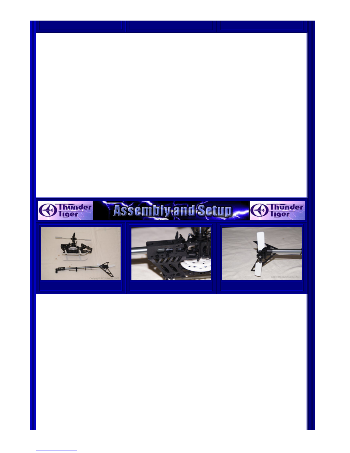
A proper bench setup and a careful pre-flight inspection
minimize surprises during your trim flights. The Mini Titan was
no different and there were no surprises as the helicopter lifted
smoothly into its first hover. Well there was one surprise. The
warped blades that I wasn't happy with seemed to track very
well.
I spent my first three battery packs making sure the helicopter
was properly trimmed, that the gyro was properly set up, and
just getting the feel for the helicopter. My first impression was
that even without flybar weights the Mini Titan was extremely
stable in the hover. I found out pretty quickly that the cyclic
was too sluggish so I knew my first tweak would be to move the
washout arms to the outer most setting. (see photo at right)
The second day out it was time for a little thrashing about. The
Mini Titan handled everything that I could throw at it. Tight flips,
Smile for the camera!
Page 9

large loops, smooth rolls, funnels, tail slides (this is how I test
the gyro); even piro flips were no problem. At this point I tried
some fast circuits and found the Mini Titan tracked very well
both upright and inverted. It maintained this behavior even
after I increased the cyclic response by moving the washout arm
balls outward.
Good pilots at our field are easier to find than a camera man so
at this point I turned over my transmitter to a very
accomplished pilot. Team Flight Power pilot Bobby Smith was on
hand the day I was working on the Mini Titan and he agreed to
do the honors for the video review flight.
If the Mini Titan can stand up to Bobby it shouldn't give a mortal
pilot any troubles. After seeing him fly your helicopter you will
appreciate that in most cases it isn't our equipment holding back
our flying, it's our thumbs. Bobby flew the Mini Titan exactly as I
built it, with the stock motor and speed controller and a Flight
Power 2500mah 3s 18C battery.
See Bobby Smith putting the Mini Titan through its paces.
(Large file)
Click HERE for small file.
The Thunder Tiger Mini Titan is a great little helicopter. For a beginner, setup with conservative
throws, it would make an excellent primary trainer. It didn't exhibit any of the twitchy control
response often observed in smaller helicopters. Extensive flying over several weekends didn't turn up
any weak points or bad habits.
The Mini Titan also makes a great little practice machine for intermediate and advanced pilots. With a
family, a busy work schedule, school, and working on reviews, I find very little time for general flying.
As a result I felt that my flying progress was becoming stagnant. One of the primary advantages of
the small and quiet electric helicopters is that they can be flown in any reasonably sized park and
there just happens to be a soccer field just a short drive from my house. Flying just two or three
battery packs a couple times a week after work I found that my flying improved significantly.
The stock motor and speed controller combination lets you try any maneuver the bigger helicopters
are capable of. Great parts support and low cost give you the confidence that the occasional
inadvertent upgrade opportunity won't put you in the dog house with the Chief of Domestic Relations.
Speaking of upgrade opportunities. I had the opportunity to fly Bobby Smiths Mini Titan equipped with
a Hacker motor and a full Gforce metal rotor head. The Hacker motor is a little power house and
there was nothing that I could do that the Mini Titan couldn't do with ease, it felt like I was flying a
90. Look for an upcoming article as Gforce has agreed to supply a rotor head for RCUniverse to
review and I plan on keeping the Mini Titan and upgrading the motor.
Page 10

Thunder Tiger Mini Titan ARF
Sold by:
AMainHobbies.com
349 Huss Drive
Chico, CA 95928
Phone:(800) 705-2215
International: (530) 894-0797
Website: www.amainhobbies.com
Flight Power Batteries
Flight Power USA Inc.
171A Weaverville Hwy
Asheville, NC 28804
Phone: (919) 741-6310
Web Site: www.flightpowerusa.com
Product used: Flight Power EVO Lite 3S 2500Mah, Flight Power EVO 25 3S 2170Mah
Hitec
Hitec RCD USA, Inc.
12115 Paine St.
Poway CA, 92064
Phone: 858.748.6948
Web Site: http://www.hitecrcd.com
Product used: HS-56HB Micro Servos
Futaba Radio Equipment
Distributed in North America by Great Planes Model Distributors 3002 N. Apollo Drive
Champaign, IL 61822
Phone: (217) 398-8970
Web Site: www.futabarc.com
Product used: Futaba 9C Super, GY-401, S9650, R148DP
Comments on RCU Review: Thunder Tiger Mini Titan E325
Profile
Page: 1
Posted by: julways on 02/09/2008
The comments, observations and conclusions made in this review are solely with respect to the particular item the editor reviewed and may not apply
generally to similar products by the manufacturer. We cannot be responsible for any manufacturer defects in workmanship or other deficiencies in
products like the one featured in the review.
EMAIL THIS ARTICLE OR CHECK OUT THESE OTHER GREAT REVIEWS!
Photo Manufacturer Product Summary Reviewed
Page 11

Weak Signals
Toledo Show
2015 -
Stepcraft
Some of you may remember Erick Royer from
his days at RCUniverse. Well, these days,
Erick is working on a new business called...
04/19/2015
GearBest
SYMA X11C
Quadcopter
Recently, gearbest.com gave me the
opportunity to review two of these
inexpensive quads. In addition to reviewing
them, I wil...
03/21/2015
Tactic
TTX850 2.4gHz
SLT Transmitter
They've got a lengthy list of features as well between the quad-bearing gimbals and
high-resolution backlit LCD display, it...
02/22/2015
Heli-Max
200FP V-CAM RTF
Fixed-Pitch Heli
Recently, Heli-Max has been releasing
quadcopters to keep up with the demands for
these stable aircraft. They haven't forgott...
02/15/2015
Ares
Optim 80 CP
Helicopter RTF
Ares and Firelands products are distributed in
the US by Hobbytown.com, who recently
asked if I'd review their new entry in t...
01/24/2015
Graupner
Polaron EX
Charger Combo
When you have a rechargeable battery,
you're going to need a way to recharge it this can be as simple as a 'wall wart' or b...
12/27/2014
Dromida Kodo Micro Quad
"You can pay two — even three — times more
for a camera-equipped quad if you want to.
But why would you do that when you can ...
11/23/2014
RCGF
60cc Twin
Cylinder Gasoline
Engine
While RC gas engines have been around for
quite a while, the demand for high quality
twin cylinder variants is fairly recent....
11/15/2014
Ares Ethos HD and FPV
Meet the Ethos HD and FPV - as their names
indicate, one carries an HD camera while the
other has FPV equipment. The HD versi...
11/15/2014
Dromida Ominus Quad
When I opened the shipping box, one of the
first things I read on the container was 'nearly
indestructible'. This piqued my i...
11/02/2014
The World
Models
Ultimate Biplane
27% (50cc) ARF
A little extra power never hurt anything, so I
figured the plane and engine would go well
together. The 27% Ultimate has been...
10/25/2014
RCGF
30cc Twin
Cylinder Gasoline
Engine
RCGF, a Chinese manufacturer of gasoline
engines, designs and manufactures engines
specifically for the RC aircraft market. T...
08/26/2014
LHS Electronics
Lektron Compact
Charger
The Lektron 35 Watt charger, made by LHS
Electronics and distributed by Hobby People,
claims to do just that! Simply plug in ...
08/24/2014
Page 12

The World
Models
P-47D
Thunderbolt
While not a new release from the World
Models, I felt that their 1/7th scale P-47
deserved a proper product review. It's been...
08/11/2014
Ares Exera 130CX
It seems that everywhere I look, I see 'toy'
helicopters. All the stores are carrying the
latest models of the little coaxial...
06/21/2014
Return to Magazine Homepage
RCUniverse is a service of Internet Brands, Inc. Copyright © 2001-2015.
Terms of Service
|
Privacy Policy
GET FREE RC CONTENT FOR YOUR WEBSITE
Search
|
Marketplace
|
Event Central
|
Local Clubs
|
Magazine
|
Product Ratings
|
New Products
|
Discussion Forums
Photo Gallery
|
Instructor Search
|
Field|Track|Marina Search
|
RCU Youtube Channel
| |
RCU Twitter!
Member Locator
|
Advertisers
|
Hobby Vendor Resources
|
Rate Manufacturers
|
Sign In/Sign Up
Products Videos WattFlyer.com RC Classifieds
RCU4 | 10.19.111.254 | 0 | 1 | 03:37:33 AM EST | NC
 Loading...