

Page 1
WARRANTY
Thunder Tiger Model Company guarantees this model kit to be free from defects in both material and
workmanship at date of manufacture.This warranty does not cov er any components damaged by use or
modification and in no case shall Thunder Tiger’s liability exceed the original purchase price of the kit.
Thunder Tiger also reserves the right to change or modify this warranty without notice.
Since Thunder Tiger Model Co. has no control over possible shipping damages or construction techniques and materials used for construction by the modeler, no liability can be assumed nor accepted for
damage resulting from the use by the user of the final user-assembled product.By the act of using this
user-assembled product, the user accepts all resulting liability.If the buyer is not prepared to accept this
liability, he should return this kit in new and unused condition to the place of purchase for a full refund.
Assembly Instructions
Item No. 4574
JE6640
Specifications:
Wing Span: 44"(1116mm)
Length: 35 1/4" (896mm)
Weight: 37~40 oz.(1050~1150g)
Engine: .10~.15 req'd
Radio: 3~4 channel req'd
Page 2
2
INTRODUCTION
INTRODUCTION
All of us at Thunder Tiger want to thank you for choosing the best looking, easiest building and best
flying ARF trainer availab le the ...Dragonfly 15.This kit features state-of-the-art engineering that provides
quick and easy assembly of a strong, yet lightweight airplane that will give you an enjoyable and
educational experience.
To gain the most from this air plane kit, it is important that you read the instructions thoroughly and then
follow them e xactly.This instruction manual has been written with a novice modeler in mind, but includes
many hints and modeling tips that even experienced modelers can benefit from. We strongly suggest
that you read through the instructions completely before beginning construction.This will give you a good
idea of the construction sequence and eliminate many questions you might have if you did not read the
manual prior to starting the actual construction.
The first thing you should do before beginning assembly is to check the contents of your kit against the
parts list on page 4. If any parts are missing, contact your dealer immediately for replacement.
Customers in the United States and Canada may contact Ace Hobby Distrib utors at 2055 Main Street,
Irvine, CA 92614 1-949-833-7498 for replacement parts. Under no circumstances can a kit be retur
ned
if assemb
ly has already been started.
Introduction
.............................2
Other Items Required
................... 2
Items Need Check List ................. 3
Parts List
.............................. 4
Pre-Assembly Notes
.................... 5
Wing
................................... 5-6
Tail Feathers
............................ 6
Fuselage ............................... 7
Install the Engine........................8-9
Control Horn............................ 9-10
Servo Installation........................10-12
Radio Adjustment........................13
Balance
.................................14
Pre-Flight Check
........................15
Post-Flight check list.....................16
A checklist is also provided on the next page
which willmake shopping for these items easier.
TABLE OF CONTENTS
OTHER ITEMS REQUIRED
FOR ASSEMBLY
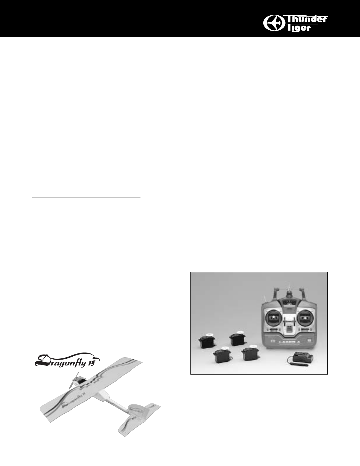
Radio - A 4-channel radio with four standard
servos is required. Most lower priced 4-channel
radios only come with three standard servos
so you may need to purchase the four th servo
separately.
Page 3
3
ITEMS NEEDED
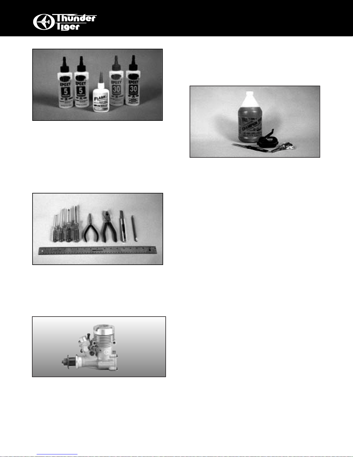
Adhesives - You will need two types of adhe-
sives for the Dragonfly - Epoxy and Instant
(cyanoacrylate) adhesives.We recommend that
you purchase both 5-minute and 30-minute
epoxy to cut down on assembly time, but you
can get by with only 30-minute epoxy if time is
not important. You will also need a small bottle
of both “Thick” and “Thin” instant adhesive.
Tools - Model assembly can be much easier if
the proper tools are used. Therefore, we have
included in our checklist to the right, a complete
listing of all the tools we used to assemble
our prototype models. As you will notice, many
household tools can be utilized during construction.
Engine - The Thunder Tiger GP-15 is the ideal
engine for this airplane. This quiet running
engine is easy to start, requires no special
break-in periods, is very easy to maintain and
will last for years.
Flight Equipment - There are several “support”
items that you will need to purchase in order to
get your engine running and your plane in the
air.These are listed at the bottom of the page.
Comprehensive Items Needed
Check List
❏ 4-Channel Radio with 4 Standard Ser vos
❏ 5-Minute Epoxy (4 ounces or so)
❏ 30-Minute Epoxy (4 ounces or so)
❏ “Thin” Instant Adhesive (1/2 ounce)
❏
“
Thick” Instant Adhesive (1/2 ounce)
❏ Hobby Knife and Blades
❏ Epoxy Mixing Sticks and/or Brushes
❏ Sandpaper (80, 150 grit)
❏ Masking Tape
❏ Rubbing Alcohol
❏ Paper Towels
❏ Ruler
❏ 90 Degree Triangle
❏ Waxed Paper
❏ Fine-Point, Felt-Tip Pen
❏ Misc. Household Tools
❏ Drill and Bits (1/16", 5/64", 1/8")
Flight Equipment
❏ Foam Rubber Padding for the radio
❏ Stick on Lead Strip for balancing the plane
❏ 3 or 4 Props (see engine instructions)
❏ 10%-15% Glow Fuel
❏ Fuel Pump or Bulb
❏ Electric Starter or “Chicken Stick”
❏ Glow Plug Clip and Battery
❏ Extra Glow Plug(s)
Page 4

4
PARTS SKETCHES
No. 3268 Tank
ORDER BY BAG NUMBER ONLY
INDIVIDUAL PARTS NOT AVAILABLE
AS6271 Main Wing
Joiner(2)
Nylon T orque Horn(2)
Wing Protector(1)
Left Wing(1) Right Wing(1)
AS6272 Horizontal Tail
CA Hinge(4)
AS6270 Fuselage
Rubber Band(6)
No.3280W Spinner
2.8x8mm
Self T apping Screw(2)
Horizontall T ail(1)
Dowel(2)
AS6273 Vertical Tail
CA Hinge(2)
No. 3268 Tank
Silicone Tube(1) Straight Nipple (1)
Crank Weight (1)
Fuel Cap (1)
Vertical Tail(1)
Fuel Stopper (1)
120cc (4oz.)
Fuselage(1)
Aileron Servo Stand(2)
No.3254 Wheel
Wheel(2)
M3 Spring Washer(4)3x14mm Machine Screw(4)M3 Washer(4)M3 Nut(4)
AS6275 Linkage Set
Guide Tube(1)
Piano Wire(1)
CA Hinge(6)
Back Plate(1)
Spinner(1)
90-degree Nipple (1)
PE0009 Hardware Set
Hex Wrench(1)
EZ Connector(1)
3x3mm Set Screw(1)
M2 Nut(1)
M2 Washer(2)
AS6274 Nylon Pushrod
Inner Rod(2)
AS6276 Main Landing Gear
Main Gear(1)
Retainer(3)
Collar(2)
Wood Screw(6)
Outer Rod(2)
3x12mm
Brass Tube(2)
Clevis(2)Z bent Threaded End(2) Straight Threaded End(2)
Tank (1)
2.6x5mm
Machine Screw(2)
AS6278 Decal
Aileron Pushrod(2)
Clevis(2)
AS6243 Control Horn
Backplate(2)
Control Horn Base(2)
Nylon T orque Horn(2)
2x22mm Screw(2)
Decal(1)
Page 5
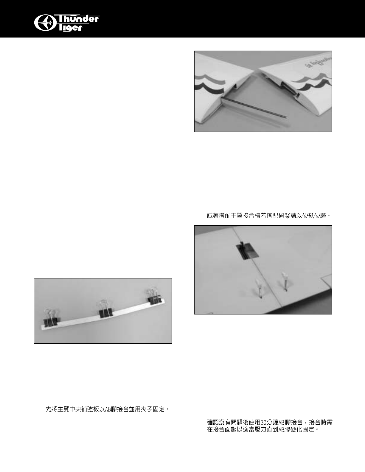
❏ 2.Tr ial fit the wing joiner into one of the wing pan-
els, sand it until it fits smoothly. Next, slide the
other wing half onto the joiner until the wing
panels meet. Mix approximately three ounces of
30-Minute Epoxy. Note: When joining the wing
halves it is extremely important to use plenty of
epoxy. Use a mixing stick or scrap piece of wood
to apply a generous amount of epoxy into the
wing joiner slot of one wing half. Ensure that the
epoxy is applied to all sides of the slot.
❏ 3.Coat one half of the joiner with epoxy up to the
centerline. Install the epoxy-coated side of the
joiner into the wing joiner slot, making sure that
the joiner is positioned correctly. Lightly coat the
epoxy on all sides of the exposed area of joiner
and wing roots as well as the slot of the other
wing half.Carefully slide the wing halves together, ensuring that they are accurately aligned.
Firmly press the two halves together and wipe
off the excess epoxy. There should not be any
gap between the wing halves.You might wisely
use mask tape to hold the wing together. Allow
the wing joint to cure.
5
PRE-ASSEMBLY
PRE-ASSEMBLY NOTE
❏
1.If you are not an experienced R/C pilot, plan to
have a fully competent pilot check your completed model and help you with your first flights.
Even though we have tried to provide you with a
very thorough instruction manual, R/C models
are rather complicated and an experienced
modeler can quickly check over your model to
make sure your first flights are successful.
❏
2.Please assemble your model according to these
instructions. Do not attempt to modify or change
in any way as doing so ma y adv ersely change its
flying characteristics.
❏
3.Before you begin, please check the entire contents of this kit against the parts list and photo to
make sure that no parts are missing or damaged. This will also help you to become familiar
with each component of your plane. If you find
that any of the parts are either missing or damaged, please contact your dealer immediately
for replacement.
Note:Your dealer cannot accept kits for return if
construction has begun.
WING ASSEMBLY
❏ 1.Locate two wing joiners and sand gently to
remove any rough edges. Apply 5-Minute epoxy
or thick CA to glue two joiners together. Clamp
the two joiners together using clothespins, or
other small clamps and wipe off the excess
epoxy before it cures. Allow the epoxy to cure
before removing the clamps.
Page 6

TAIL FEATHERS
❏ 7.Use the same way as you did on aileron to glue
the rudder and elevator on the tails. Using a
hobby knife , carefully cut out the co v ering at the
center of horizontal tail slot .The vertical tail will
later be inserted into this slot. Install the tail on
the fuselage. Use a felt tip pen or marker to
draw lines along the fuselage sides as well as
the bottom side of horizontal tail.
❏ 8.Remove the tails from the fuselage and use a
hobby knife to carefully score the covering
material where marked.Make the score approximately 1/16" (1.5mm) inside the lines you drew.
It is very important that you do not press hard
enough to cut into the wood itself or it may fail
in flight. Just score the covering and it will peel
away nicely.
❏ 4.Locate the plastic wing protector plate and light-
ly sand the edges on one side of the plate by
80-grit sandpaper. Center the plate across the
wing joint and flush with the trailing edge then
glue with thick CA.
❏ 5.To hinge the ailerons, remove the clear tape that
holds one of the ailerons in place. Pull the
aileron off the wing, revealing three hinges.
Position the hinge in the center by a ball pin or
T pin.
❏ 6.Attach the aileron to the trailing edge, remo v e all
pins then drop thin CA to the hinges at both
sides.
6
TAIL FEATHERS
Page 7

LANDING GEAR
❏ 11.Locate the main landing gear and the three
retainers. Place the landing gear and retainer
on the fuselage bottom as shown.Make marks
on the retainer holes. ( About 5” away from the
nose).
❏ 12.Drill 1/16"(1.5mm) holes on the marks you
made.
❏ 13.Screw the landing gear with the furnished six
3x12 wood screws. Insert the brass tube to the
wheel first then secure the collar with 2.6x5mm
set screw. Make sure the wheels rotates freely.
❏ 9.Apply 5-Minute Epoxy or thick CA onto the hor-
izontal tail and vertical tail along the area where
the covering were removed. Attach the hor izontal tail and vertical tail onto the fuselage.Note, it
is important to ensure that the horizontal tail is
level in regards to the fuselage and the ver tical
tail is perpendicular to the horizontal tail as
shown. Wipe off any excess epoxy and secure
by masking tape. Allow the epoxy to cure completely.
❏ 10.Trail fit the tail assembly to the fuselage.
Remove the covering at the contact area then
apply enough 5-Minute Epoxy to the contact
area inside the fuselage and do not move it
until it cured.
7
FUSELAGE
90˚
Page 8

does, simply cut a small portion of the fuel tubing until the clunk no longer reaches the rear
of the tank.
❏ 16.Cut two 5” (12cm) long of standard size sili-
cone fuel tubing (not furnished) and slip one
end onto the nipple extending out of the cap
and the other onto the top vent of the fuel tank.
Slide the fuel tank (cap end first) into the fuselage from the wing saddle area, threading the
fuel lines through the oblong hole in the firewall. The tank should fit tightly in the forward
formers.
ENGINE
❏ 17.Position the engine on the engine mount
beams so the distance from the prop hub to
the firewall is exactly 3 1/2"( 89mm). Using a
pencil or felt tipped pen, mark the engine
mounting plate where the four holes are to be
drilled. Note:Mark the mounting plate through
the engine mounting flanges. Remove the
engine and drill a 1/8"(3mm) hole through the
beam at each of the four marks.
❏ 14.Locate the four pre-drilled wing dowel holes,
two on either side of the fuselage. Using a
sharp hobby knife, carefully cut the covering
away from each of the holes Insert one of the
wooden dowels into each of the wing dowel
holes. Ensure that an equal amount of dowel
extends from each side of the fuselage. You
might apply a thin coat of epoxy to the wing
dowels to prevent the dowels from becoming
fuel-soaked during flight.
FUEL T ANK
❏ 15.Locate the fuel tank and the fuel tank acces-
sories. Assemble the fuel tank by first cutting
the silicone tube to 2"(53mm) in length. Press
the straight plastic nipple (the 90-degree nipple is not used in this plane) into the rubber
stopper until the molded-in ring is against the
stopper. Rubbing alcohol applied to the nipple
will make it slip into the stopper easier. Now
slip the silicone tubing onto the nipple and
insert the metal clunk into the other end of the
tubing. Insert this assembly into the tank
(clunk first) and securely tighten the threaded
cap on to hold everything together. Note: It is
important to ensure that the fuel tank clunk
does not touch the rear of the fuel tank. If it
8
INST ALL THE ENGINE
Page 9

❏ 20.Locate the plastic pushrod tube through the
pre-drilled hole in the firewall of the fuselage
until approximately 1/2"(1.5mm) of the tube
protrudes from the firewall. Secure the tube
with 5-Minute Epoxy. Locate a Z bent throttle
pushrod, Slide the wire, straight end first, into
the pushrod tube. Insert the Z bent into the
hole on the throttle lever of your engine. Note:
It may be easier to temporarily remove the
throttle lever from the engine to insert the Z
bent end.
CONTROL HORNS
❏ 21.Locate the linkage rods include straight thread-
ed end, Z bent threaded end , nylon inner rod.
Thread the nylon rod onto the straight thread
end first as shown. At least 3/8"(9mm) in
length.
❏ 18.Using a Philips screwdriver, firmly secure the
engine by four 3x14mm machine screw, M3
spring washers, M3 washer and M3 nuts.
Install the muffler as per the instructions
included with the engine. Connect the vent
tube from the fuel tank to the nipple, or pressure fitting, on the muffler.The remaining fuel
tube should be attached to the carburetor inlet
nipple.
❏ 19.Remove the propeller nut and prop washer
from the engine. Install the spinner back plate
on the crankshaft, followed by the propeller,
the prop nut and finally the spinner nose cone.
Securely attach the spinner nose cone to the
spinner back plate using the two screws provided in the hardware bag and a Philips
screwdriver.
9
CONTROL HORNS
Page 10

❏ 24.Attach the control horn using the hardware pro-
vided ( 2x22mm screws, back plate, control
horn base and nylon horn) and fasten in place
using a Philips screwdriver. Make sure the
back plate and control horn base are both in
line at two sides on the elevator. Thread the
nylon horn on to the screw then snap the clevis onto the horn.
SERVO INSTALLATION
❏ 25.Thread the Z bent threaded end to the nylon
inner rods as shown. Before you thread, it
might need to cut the nylon rod as it is too
long. Note the servo orientation in the next
step.Refer to the photo, mak e sure y ou thread
the Z bent threaded end to the nylon rod for
3/8"(9mm) in length and the Z bent end is
about at the position of servo horn where is
going to link.
❏ 22.Insert the pushrod to the holes on former, the
lower one is elevator pushrod and the other is
rudder pushrod. Attach the plastic clevises at
least 1/4"( 6mm) in length.
❏ 23.Turn the fuselage over and place one of the
control horns on the bottom of the elevator.
Hold the control horn against the bottom of
the elevator so it is approximately 1/8" (3mm)
behind the hinge line and in line with the
pushrod exit hole.Using a felt tipped pen or a
pencil mark the mounting hole positions.
Remove the control horn and drill two 5/64"
(2mm) holes through the elevator as shown.
10
CONTROL HORNS
Page 11

❏ 26.Refer to manual of radio then install the rubber
grommets and eyelets which come with your
servos. Secure the servo with the servo screw
as shown. Attach the Z bent end to the ser vo
horn . With radio is on and centered, adjust
the pushrod length either by threading the clevis or Z bent threaded end so the elevator is
level when servo is in neutral position with
servo horn installed.
❏ 27.Same procedure on r udder servo. We recom-
mend you use the servo arm instead of round
servo horn on rudder ser vo.
❏ 28.When everything is set, slip a short piece of
fuel line over all clevises to prevent them from
snapping open in flight.
❏ 29.Locate the EZ connector set which includes
3x3mm set screw, two M2 washers, m2 nut
and an EZ connector. Install the connector on
the servo arm as shown. It might need to
enlarge the hole on servo arm to make sure it
rotates freely. It is wisely to apply little CA to
the M2 nut from loosing.
❏ 30.Align the pushrod tube with the throttle servo.
To prevent any possible binding, the pushrod
tube should be shortened so it does not interfere with the servo arm travel. Using a sharp
hobby knife, cut the pushrod tube accordingly.
Insert the pushrod wire through the pushrod
connector. Secure the pushrod in place using
a 3x3mm set screw.
11
SERVO INSTALLATION
Page 12

❏ 31.The switch should be mounted on the left side
of the fuselage, using a sharp hobby knife
carefully cut the opening for the switch.Detach
the switch plate from the receiver switch harness. Using the switch plate as a template,
Drill the two mounting holes using a 5/64" drill
bit.Secure the switch in place as shown.Route
the antenna back through the fuselage or
route it outside the fuselage back to the vertical tail.
❏ 32.Locate two aileron servo stands. Remove the
covering where is going to glue the stand as
shown. Apply 5-Minute Epoxy to the aileron
servo stand. Remove any excess epoxy and
allow epoxy to cure.
12
SERVO INSTALLATION
❏ 33.Install the r ubber servo grommets and eyelets
in the aileron servo. Next, secure the aileron
servo in place as illustrated.
❏ 34.Locate two aileron torque rod horns, two long
Z bent threaded aileron pushrod and two clevises. Thread the horns on aileron torque rod
until the threaded portion is flush with aileron
torque rod horn. Next, thread the clevises on
pushrod.With the aileron servo horn in its neutral position, insert the Z bent end of two
pushrods to servo arm. Snap clevises onto
aileron torque rod horns. Adjust the clevis to
make sure two ailerons are level with trailing
edge.Thread a small piece of fuel tube to hold
clevis.
Congratulations
You are ready to fly. Don't forget to balance your
plane and fine tune the all control surfaces.
Page 13

13
RADIO ADJUSTMENT
❏ Adjust the linkages so you get the proper amount and direction of control throws as illustrated. To
INCREASE the amount of movement, move the linkage outward on the servo arm OR inward on the
control horn. To DECREASE the amount of movement, move the linkage inward on the servo arm OR
outward on the control horn.
UP
UP ELEVATOR
DOWN ELEVATOR
RIGHT AILERON: Aileron on the right moves
upward; aileron on the left moves downward.
HIGH THROTTLE
LOW THROTTLE
LEFT AILERON: Aileron on the left moves
upward; aileron on the right moves downward.
1/2” UP
1/2” DOWN
1/4”
UP
5/16”
DOWN
DOWN
ELEVATOR AILERONS
THROTTLE
LEFT RUDDER RIGHT RUDDER
1/2” LEFT
1/2” RIGHT
RUDDER/NOSE WHEEL
Page 14

14
BALANCE
BALANCING Y OUR PLANE
IMPORTANT- Do not attempt to fly your model
before completing this very important section.
A model that is not properly balanced will be unstable and could cause serious damage and/or injury.
The balance point for this model is 3"(75mm)
behind the leading edge of the wing. Measure this
distance and mark it on both sides of the fuselage
right under the wing. With your model fully assembled but without fuel, pick it up with your index fingers at each of the two balance marks you made
earlier.If balanced proper ly, the plane will hang horizontally. If the plane hangs with the tail down, then
you need to add (or redistribute) some weight in the
nose. Usually the plane will either balance or hang
slightly tail heavy. The easiest cure for a tail heavy
plane is to move the receiver and battery forward as
far as possible. If the plane hangs nose down, then
you need to add some weight to the tail. Stick-on
lead weights are available from your hobby dealer
that will make adding weight a simple task. Once
you have everything positioned as necessary, wrap
your receiver and battery pack in 1/4" or 1/2" thick
foam for protection.
PRE-FLIGHT
If you are an experienced pilot, some of the
following text will not apply to you. Simply
disregard references to “your first flights.”
LOCATE A GOOD FLYING SITE
Generally, the best place to fly your model is
at an AMA (Academy of Model Aeronautics)
chartered club field.Your local hobby dealer can
tell you if there is such a club in your area or
write the AMA for information. It is also a good
idea to join this organization before flying your
model since they offer liability insurance that
can protect you if your model causes damage or
injury to others.
Academy of Model Aeronautics
5151 East Memorial Dr.
Muncie, IN 47302-9252
If there is not a chartered club field in your community, you will need to find a large area free of
obstructions, that has a smooth grass or asphalt surface to be used as a runway. For safety’s sake, it
should be located well away from houses, building,
schools, power lines and airports. If you will be flying
within 6 mile of an airpor t, you should check with the
airpor t manager before flying your model.
ANOTEONBATTERIES
The batteries are the heart of your radio system.
Make sure you have fully charged batteries! With
rechargeable batteries, follow the manufacturers
instructions to make sure the batteries are fully
charged, especially the first time the radio is used.
3" (75mm)
Page 15

15
PRE-FLIGHT CHECKS
If your radio uses dry cells, make sure your batteries are in new condition.You have a lot of money
invested in this project so it is not worth the risk of
using old batteries.
PRE-FLIGHT CHECKS
You should perform these checks before each flying session.
❏ 1. Check all control surfaces for possible loose-
ness or deterioration.
❏ 2. Check all screws, rubber band, clevises, nuts
and all other connectors to make sure they are
securely fastened.
❏ 3. Check which radio frequencies are being
used. Do not turn on your radio until absolutely sure you are the only one operating on that
frequency.
❏ 4. Check for proper operation of all control sur-
faces.
❏ 5. Check the level of charge in both the transmit-
ter and receiver batteries before flying.
❏ 6. Range check the radio both with and with-out
the engine running! Follow the radio manufacturers instructions for this.
FLYING
Learning to fly a radio control aircraft can be very
exciting, but it is important that you thoroughly
understand the basics of flight and controls before
you attempt your first flights. Therefore, we highly
recommend that you seek the expertise of an experienced instructor pilot for the first few flights.He (or
she) can get you in the air much more smoothly than
trying everything yourself for the first time. Specially
this plane is not good for taking off from the ground.
It is better have experienced modeller to launch the
plane and test the plane for you.
GETTING ORIENTED
The first and most important thing to remember
when controlling model aircraft is:the model controls
are set up to operate as if you were sitting in the
cockpit of the model.This means that when you pull
back (down) on the elevator stick the nose of the
plane will go up. Moving the rudder stick to the right
will “yaw” the plane to the right and moving the
aileron stick to the right will “roll” the plane to the
right. Pretty simple right? Well, not quite. Since you
are really standing on the ground and not sitting in
the plane, this is how the controls work when you are
facing the same direction the plane is flying. The
problem is that when the plane is flying towards y ou,
the rudder and aileron controls seem reversed to the
inexperienced pilot. This is the reason we recommend that you practice taxing around in a large open
area to try and get used to the control reversal.
During your first few flights, tr y to face the direction that the plane is flying and looking over your
shoulder as needed. This makes it a little easier to
pretend that your sitting in the cockpit.
FIRST FLIGHT
When you are comfortable with the controls, you
should be ready for your first flight.Go over the PreFlight Check List one more time for good measure.
Point the model directly into the wind at full throttle.
Launch the plane against the wind by another experienced modeller.As the model starts rolling forward
it may try to turn to the left due to the engine torque.
Apply enough right rudder to keep the plane rolling
relatively straight into the wind.If you built the model
with right thrust, this tendency may not be noticeable. As the plane picks up speed, the right r udder
input can be reduced.
Once the plane reaches flying speed and height,
it will probably try to fly by itself. It is always important that you do not apply too much up elevator too
early or the plane will stall and roll over into the
ground.
As the plane becomes airborne, reduce the “up”
elevator and allow the plane to pick up flying speed
while gently gaining altitude. Once a safe flying
speed and altitude has been obtained, feel free to
turn the airplane back toward the flying field. Make
all control inputs smoothly and gradually so you can
see the effect they have on the plane. A small
amount of “up” elevator will need to be applied to
keep the plane lev el during turns.You should be able
to reduce the throttle to about 1/2 throttle for normal
cruising flight which will reduce the flying speed and
give you more time to think about what is going on.
You will find that once airborne, you can fly the plane
with only the aileron and elevator sticks. This is perfectly fine and will make it much easier for you to
learn.
If the plane has a tendency to turn, roll, climb, or
dive, you can adjust the transmitter trims to correct
this. On your first flights, it might be a good idea to
Page 16

16
POST-FLIGHT CHECK LIST
have an experienced pilot make the adjustments for
you while you fly the plane.
If you get disoriented or the plane gets out of control, simply take your hands off all the controls and
allow the plane to stabilize. Clear your head and try
to picture yourself sitting in the cockpit. Then input
the required control movements to get the plane
back on the correct flight path. If you run out of time
or flying space and realize the plane is going to hit
something (ground, tree, etc), pull the throttle back to
idle and pull the elevator stick back about half way.
This will reduce the speed of the plane and minimize
the damage sustained.
When you are ready to land, do a couple of slow
fly-bys at a safe altitude to get familiar with the
plane’s slow-flying characteristics. An important factor to remember here is that you should regulate
your altitude with the throttle not the elevator as you
might expect. Practice raising the nose of plane
slightly with a touch of “up” elevator and then using
the throttle to regulate the plane’s altitude.When you
are ready to land, fly downwind past the runway.
When the plane is a hundred yards or so downwind,
reduce the throttle to almost an idle and turn 90
degrees towards the runway. Fly straight for a second or two until the plane is almost even with the
runway.T urn 90 degrees again and fly directly tow ard
the runway using the throttle to govern how quickly
the plane is descending. Keep the nose of plane up
slightly with the elevator and allow the plane to fly
gently onto the runway. Do not try to stretch the glide
path without increasing the throttle or the plane may
stall.
POST-FLIGHT CHECK LIST
❏1. Be sure that both the transmitter and
receiver switches are turned off.
❏ 2.Drain all excess fuel from the tank.Fuel left
in the tank for extended periods can “gunk
up” the tank, fittings and carburetor.
❏ 3. Clean the plane with paper towels and a
light-duty spray cleanser. Keeping your
plane clean will make it last longer and
keep it looking nice.
❏ 4.Put a few drops of after-run or light oil in the
carburetor and turn the prop over a few
times (without the glow plug ignited) to distribute the oil throughout the engine.
❏ 5. Inspect the prop and replace it if any chips
or cracks are found.
❏ 6. Inspect the entire plane for covering tears,
new dings and dents, loose screws and
connectors and any other wear and tear.
❏ 7. Use a voltmeter to check the receiver bat-
tery voltage. If it is low, you now know not
to fly so long next time.If it is still high, you
should be able to fly a little longer next
session.
SAFETY PRECAUTIONS
1. Wear safety glasses when star ting and run-ning
all model engines.
2. Model engine fuel is very flammable and the
flame is very dangerous because it is almost
invisible! Do not smoke or allow sparks, high heat
or other flames near the fuel.
3. Do not run model engines inside a garage or
other closed room as they give off large amounts
of deadly carbon monoxide gas.
4. Do not run model engines around gravel, sand or
other loose debris.These materials will be ingested through the carburetor and can also be kicked
up by the prop.
5. Always stay behind the propeller when the engine
is running. Make all engine adjust-ments from
behind the engine. Under no circumstances
should you allow your face or body near the plane
on rotation of the propeller when the engine is
running.
6. Do not allow loose clothing or other loose objects
close to the prop.
7. To stop an engine, cut off the fuel or air supply to
the engine.Do not throw rags or other objects into
the prop to stop the engine.
8. Do not touch the engine or muffler during or right
after it has been running–It gets very hot!
9. If you hear any unusual noises while your plane is
flying, land at once and determine the problem
before returning to the air. Control surface flutter,
which often emits a low-pitched “buzz”, can
quickly destroy an airplane and should not be
ignored. Flutter is usually caused by sloppy control surfaces and is generally relatively easy to
cure.
 Loading...