

Page 1
1
Thunder Tiger Cloud Dancer 40 ARF (TTR4542)
Distributed in North America by Ace Hobby Distributors,Inc.• 116 W 19th ST,Higginsville,MO 64037
660-584-7121 • www.acehobby.com • ser vice@acehobby.com
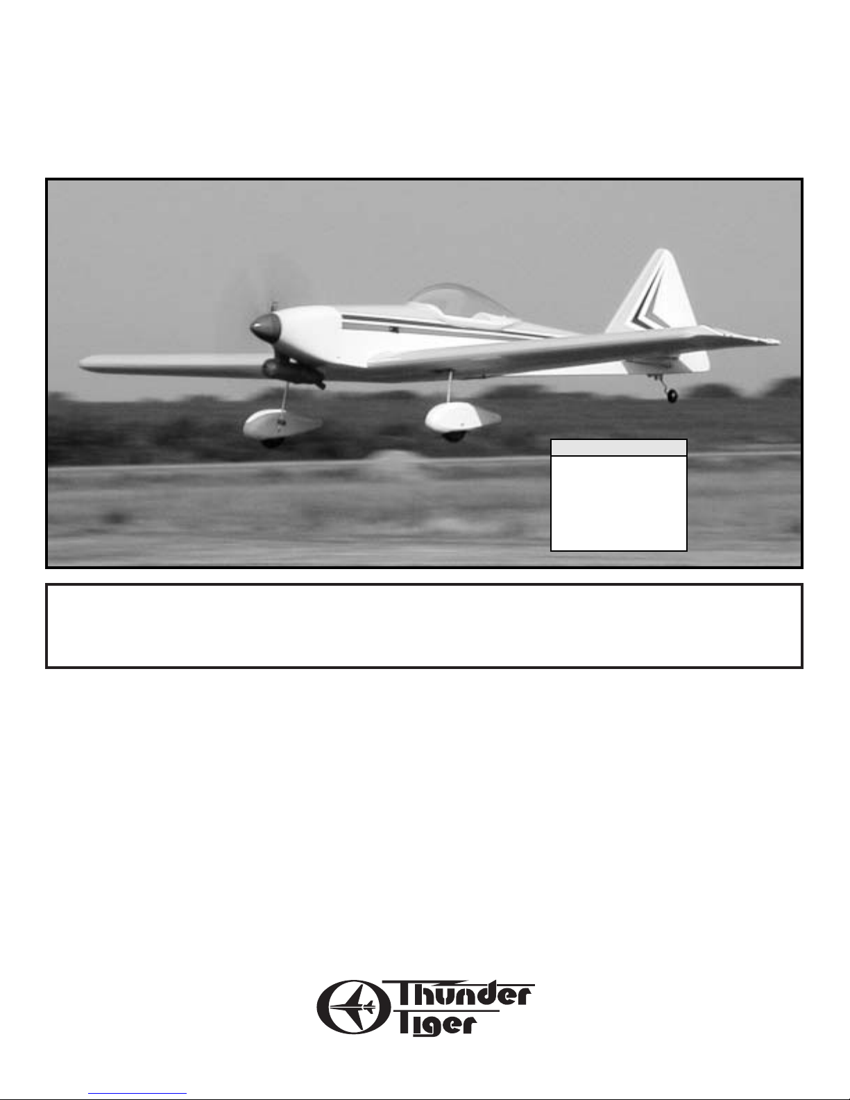
Cloud Dancer 40 ARF
Assembly Manual
Wingspan: 60”
Length: 46.75”
Wing area: 625 in
2
Weight: 4lbs
Engine: .40-.46 2 Cycle
.40-.53 4 Cycle
Radio: 4 Channel
Specifications:
Warranty
This kit is guaranteed to be free from defects in material and workmanship at the date of purchase.
It does not cover any damage caused by use or modification. The warranty does not extend beyond the
product itself and is limited only to the original cost of the kit. By the act of building this user-assembled
kit,the user accepts all resulting liability for damage caused by the final product. If the buyer is not
prepared to accept this liability,it can be returned new and unused to the place of purchase for a refund.
21041/JE6439
Notice: Adult Supervision Required
This is not a toy. Assembly and f lying of this product requires adult supervision.
Read through this book completely and become familiar with the assembly and f light of this airplane.
Inspect all parts for completeness and damage. If you encounter any problems,call 660-584-6724 for help.
Page 2
2
INTRODUCTION
All of us at Thunder Tiger want to thank you for choosing one of the finest 40 sized sport planes available,the Cloud Dancer 40. Designed by the
late Fred Reese, this airplane offers a unique appearance and sprightly, yet predictable performance. This model features state-of-the-art
engineering that provides quick and easy assembly of a strong,yet lightweight airplane that will give you an enjoyable and thrilling experience.
To gain the most from this airplane kit, it is important that you read the instructions thoroughly and then follow them exactly. We strongly
suggest that you read through the instructions completely before beginning construction. This will give you a good idea of the construction
sequence and eliminate many questions you might have if you did not read the manual prior to starting the actual construction. Due to the nature
of this design,this airplane is not intended for a beginner’s first model and the instructions are written with this in mind. We assume you have a
working knowledge of airplane and radio terminology.
The first thing you should do before beginning assembly is to check the contents of your kit against the parts list on pages 4 and 5. If any parts
are missing,contact your dealer immediately for replacement.Customers in the United States and Canada may contact Ace Hobby Distributors at
116 W. 19th Street,Higginsville,MO 64037 (660) 584-6704 for replacement parts.Under no circumstances can a kit be returned if assem-
bly has already been started.
P.S. Fred Reese was a dear friend. The Cloud Dancer is the first in a line of re-releases of his designs since his untimely death.We are proud to be
able to continue to offer his fine airplanes so we can keep his name alive in our small way.
Tom Runge,Ace Hobby Distributor s, Inc.
Experienced pilots who want to maximize their enjoyment of the
Cloud Dancer 40 should consider installation of the optional retracts.
The instructions have complete details.
See your hobby dealer for addition information on these 40 sized
retracts,Thunder Tiger part number 3007.
You will also need a 180º retract servo that is compatible with your 5
or more channel radio system.
OPTIONAL RETRACTS
TTR3007
A checklist is also provided on the next page which will
make shopping for these items easier.
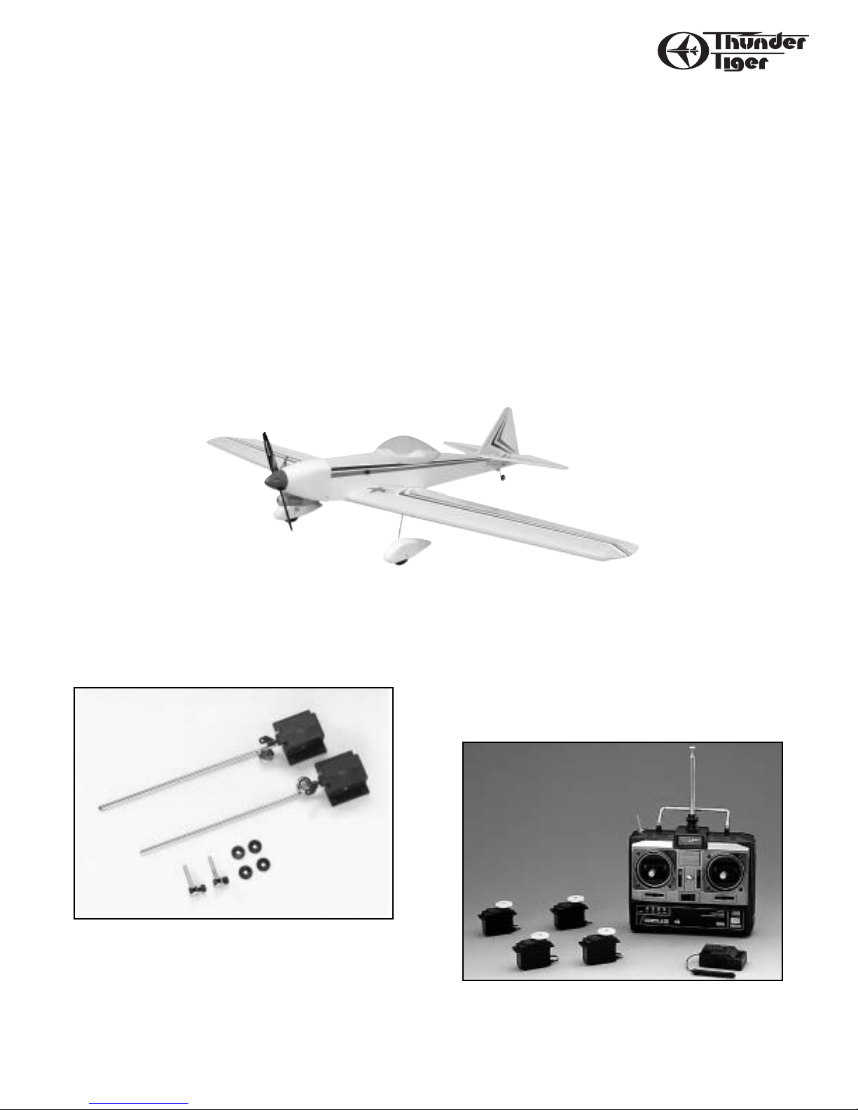
OTHER ITEMS REQUIRED
FOR ASSEMBLY
Radio - A 4-channel radio with four standard servos is required.
(If you are installing retracts, you need a radio that has at least 5
channels and a 180º Retract Servo that is compatible.)
Page 3
3
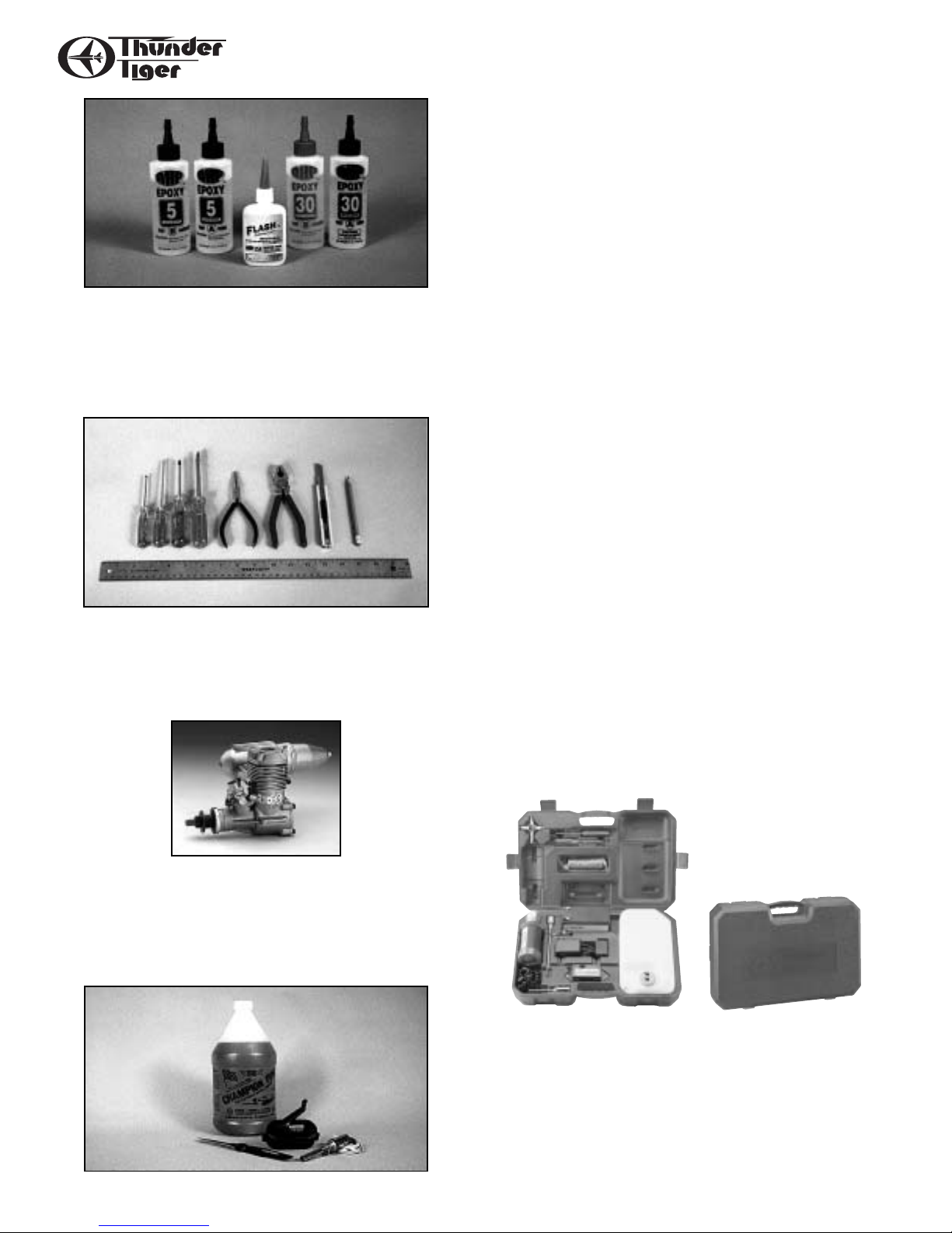
RECOMMENDED TOOLS & MATERIALS
Adhesives - You will need two types of adhesives for this ARF Epoxy and Instant (cyanoacrylate) adhesives. We recommend that you
purchase both 5-minute and 30-minute epoxy to cut down on
assembly time,but you can get by with only 30-minute epoxy if time
is not important. You will also need a small bottle of both “Thick”and
“Thin”instant adhesive.
Tools - Model assembly can be much easier if the proper tools are
used. Therefore, we have included in our checklist to the right,
a complete listing of all the tools we used to assemble our prototype
models. As you will notice, many household tools can be utilized
during construction.
Engine - The Thunder Tiger PRO-46 is the ideal engine for this airplane.It is a quiet running engine that is easy to start and require no
special break- in period,is very easy to maintain,and will last for years.
Flight Equipment - There are several “support”items that you will
need to purchase in order to get your engine running and your plane
in the air.These are listed at the bottom of the page.
Comprehensive Items Needed Check List
❏ 4-Channel Radio with 4 Standard Servos
❏ 5-Minute Epoxy (4 ounces or so)
❏ 30-Minute Epoxy (4 ounces or so)
❏ “Thin”Instant Adhesive (1/2 ounce)
❏ “Thick”Instant Adhesive (1/2 ounce)
❏ Hobby Knife and Blades
❏ Epoxy Mixing Sticks and/or Brushes
❏ Sandpaper (150 grit)
❏ Masking T ape
❏ Rubbing Alcohol
❏ Paper T owels
❏ Ruler
❏ 90 Degree Triangle
❏ Waxed Paper
❏ Fine-Point,Felt-Tip Pen
❏ Misc.Household T ools
❏ Drill and Bits (
1
⁄16",5⁄64",3⁄32",5⁄32",3⁄16")
Flight Equipment
❏ Foam Rubber Padding for the radio
❏ Stick on Lead Strip for balancing the plane
❏ 3 or 4 Props (see engine instructions)
❏ 10%-15% Glow Fuel
❏ Fuel Pump or Bulb
❏ Electric Starter or “Chicken Stick”
❏ Glow Plug Clip and Battery
❏ Extra Glow Plug(s)
CARR
Y
A Breakthrough in Field Equipment!
The CarryMaster’s “Organization Plus”allows you to transport all your
field essentials in a rugged and compact case that will fit about anywhere in about any vehicle. A complete “turn-key” combo is available
as well as the case by itself.
Combo contents include:
•3 liter fuel cell
• 12v starting battery/charger
• glow starter/charger
•12v HD starter
• 4-way wrench
Page 4
4
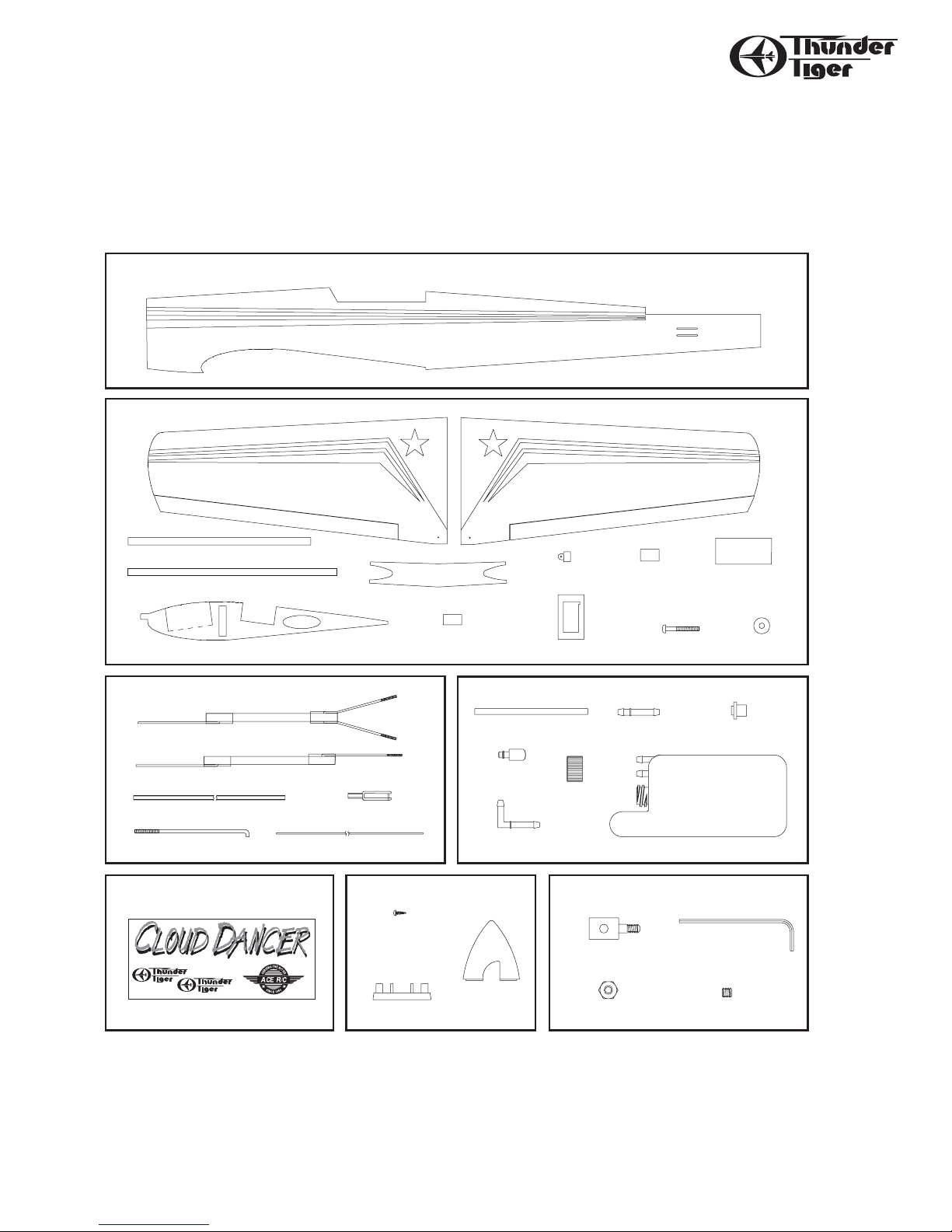
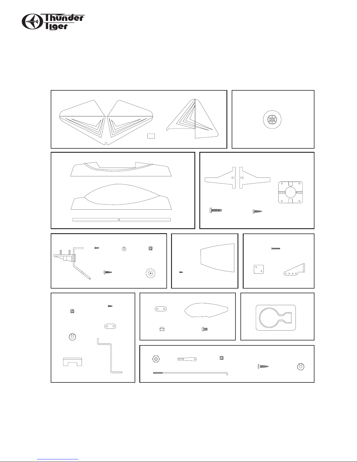
PARTS DRAWINGS
AS6128 Fuselage
AS6134 Pushrods
3282W Spinner Set
AS6136 Decal
AS6129 Wing Set
3262 Fuel Tank
PE0009 Hardware Set
Left Wing(1) Right Wing(1)
Center Rib(2)
Trim T ape L(1)
Trim T ape S(1)
Wing Joiner(3)
Torque Horn(2) CA Hinge(6) Wing Protector(1)
Aileron Servo Tray(1) Wing Bolt(2) Washer(2)
Stab Pushrod(1)
Rudder Pushrod(1)
Plastic Guide Tube(1)
Aileron Pushrod(2) 0.05" Metal Piano Wire(1)
Clevis(5)
Decal
Self-Tapping Screw(2)
Spinner Back Plate(1)
Spinner(1)
Pushrod Connector(1) Allen Wrench(1)
2mm Hex Nut(2) 3mm x8mm Set Screw(1)
IMPORTANT
Please check the contents of your kit box with these part sketches before beginning
construction. This will not only familiarize you with the parts and their names, but it
will also give you a head start in the unlikely event that you are missing a part.
Parts are not necessarily drawn actual size!
Retract Servo
Mount(2)
Fuselage(1)
Rubber Stopper(1)
Straight Nipple(1)
Silicone Tube(1)
Cap(1)
Clunk(1)
90-degree Nipple(1)
180cc (6oz)
180cc Fuel Tank(1)
Page 5
5
PARTS DRAWINGS
AS6130 T ail Feathers
AS6133 Wheel W ell
3296 Wheel
PE0585 Wheel Pant Set
3102 Adjustable Engine Mount
AS6131 Cockpit/Canopy
AS6137 Retract Hardware Set
AS6135 Landing Gear Set
AS6132 Cowl
AS6007 Tail Gear Set
AS6100 Control Horn
57mm 2 1/4" Wheel(2)
6/32 x18mm
screw(4)
3mm x 15mm
Self-Tapping Screw(4)
Beam(2, left/right)
Engine Mount Plate(1)
Wheel Well(2)
Tail Gear(1)
3mm x 8mm
Self-Tapping
Screw(1)
Collar(1) 3mm x 3mm
Set Screw(1)
Tail Wheel(1)
3mm x 15mm
Self-Tapping Screw(1)
2mm x 8mm
Self-Tapping Screw(8)
Cowl(1)
Back Plate(3)
Control Horn(3)
2mm x 15mm Screw(6)
3mm x 3mm
Set Screw(4)
3mm x 8mm
Self-Tapping Screw(8)
Mounting Strap(4)
Collar(4)
Strut(2)
Landing Gear Mount(2)
Mounting Strap(2)
3mm Locknut(4)
3mm x 5mm Screw(4)
Wheel Pant(2, L & R)
2mm Nut(2)
Steel Clevis(2)
3mm x 3mm
Set Screw(2)
3mm x 10mm
Retract Mounting Screw(8)
Collar(2)
Linkage Rod(2)
Parts are not necessarily drawn actual size!
Replacement parts must be ordered by Set Number
H. Stab/Elevator(1) V. Fin/Rudder(1)CA Hinge(7)
Cockpit(1)
Canopy(1)
Trim T ape(1)
Page 6

6
WING ASSEMBLY
I. Pre-Assembly Notes
1. Please assemble your model according to these instructions.
Do not attempt to modify or change in any way as doing so may
adversely change its flying characteristics.
2. Before you begin, please check the entire contents of this kit
against the parts list and photo to make sure that no parts are
missing or damaged. This will also help you to become familiar
with each component of your plane.
3. Each step of these instructions is preceded by a box which can
be checked off as you complete the step.This will allow you to
follow your progress and quic kly find y our starting place after any
interruptions or breaks.
Note: Your dealer cannot accept kits for return if
construction has begun.
II. Decide On Retracts
❏ Before assembling the wing,you must decide whether or not you
are going to install the optional retracts. If you fly off a grass field,we
recommend you stay with the stock fixed gear. Instructions are
provided for either event.
III. Wing Assembly (Fixed Gear)
❏ To hinge the aileron to the wing,begin by removing it from one of
the wing panels. Install the “CA”hinges into the aileron and use T-pins
to hold them in place while inserting the hinges in the wing (or simply us thin CA and permanently glue them in place in the aileron.)
❏ Install the aileron onto the wing,making sure the arm of the torque
rod goes into the hole in the aileron.Keeping the gap to a minimum,
wick thin CA onto the hinges,making sure you get glue on all surfaces.
After the glue “fires”,firmly tug on the aileron to make sure it is secure.
Repeat for the other wing panel.
❏ With a wing panel upside down on your work surface,cut away the
material that covers the landing gear block area. With the landing gear
block centered over the hole,mark around the block. Next,cut away
the balsa sheeting from this area.
❏ Note that each landing gear block has a hole pre-drilled. This hole
goes to the center of the wing. With this in mind, securely glue the
landing gear blocks in place with 30 minute epoxy. Wipe away any excess.
Page 7

7
WING ASSEMBLY
❏ Locate the three plywood dihedral braces. Using epoxy or thick
CA,glue and clamp these pairs of pieces together. Keep the edges of
the pieces lined up and wipe off any excess glue. Also laminate the
two center ribs together.
❏ Before gluing the two wing halves together, tr ial-fit the wing joiner
into both wing panels. If it is not easy to slide into the wing, sand it
until it will. To fit properly,note that the wing has an upward “bend”
in it, called dihedral. While fitting, also have the double center rib
temporarily in place.
❏ With 30 minute epoxy,liberally coat all sides and edges of the wing
joiner and slip it into one wing half. Now coat the both sides of the
double center rib where it will join to the wing halves.
❏ Join the two wing halves and firmly press wing panels together.
Wipe off any excess epoxy with a paper towel and rubbing alcohol.
Make sure the two panels are accurately aligned with each other and
hold together with several strips of masking tape.
❏ Place the servo tray on the top surface of the wing. Line it up with
the removed area in the center rib. Mark around the outside of the
servo tray with a felt tip pen.
❏ Use a sharp knife to score the covering material where marked
around the OUTSIDE of the tray. Remove the covering material to
expose the wood underneath. Use thick CA or epoxy to glue the servo
tray securely in place.
❏ Use a sharp knife to cut through and remove the covering material and balsa on the INSIDE of the servo tray.
❏ Install your aileron servo.
❏ Install the linkage between the servo and the aileron torque rods.
It consists of a nylon horn that is threaded onto the torque rod so a
few of the threads are exposed at the top,a threaded rod with a nylon
clevis screwed on one end. (Screw it on so 1/2 the threads still
remain.) To hook to the servo arm,put a “Z”bend on the other end at
the proper distance so the aileron remains in neutral.
❏ Strips of covering film are provided to trim out the center joint.You
will need to use a covering iron or a household iron to secure the film.
Page 8

8
RETRACT INSTALLATION
❏ Epoxy the wing halves together,making sure you coat all sides of
the dihedral brace plus where the ribs join. Use some masking tape to
hold the wing together as the glue sets.
❏ Cut away the balsa sheeting to expose the retract servo location.
Also cut away for the aileron servo opening. Glue the aileron servo
tray in place,removing the covering film first..
❏ Remove the covering material that covers the landing gear hole in
the bottom of the wing. Next cut away the sheeting to accommodate
the plastic wheel well. It is indicated in this photo by dotted lines.
❏Trim the plastic wheel wells as shown.
IV. Retract Installation (Optional)
❏ See page 2 for a discussion on the retracts we recommend.
Begin by hinging the ailerons to the wing panels as shown in the
section on fixed gear.
❏ Remove the forward area that houses the retract servo from the
root rib and the plywood center rib;do so for both left and right.
❏ Glue the ply center rib onto the root ribs for both left and right
wing panels.
❏ Laminate the three ply dihedral braces together.
❏Test fit the dihedral brace into both wing halves and sand as needed
for a good fit.
Page 9

9
RETRACT INSTALLATION
❏ Glue the wheel wells into the wing using a compatible glue such as
“Zap-a-dap-a-goo”,RC 56, or “Shoe-Goo”.
❏ Drill pilot holes for the retract assemblies.
❏ With a pushrod attached to the retract assembly,move it into
position and mount to the hardwood blocks. Pushrods not provided.
❏ Glue mounting blocks for the retract servo in the opening.
❏ Mount the retract servo and bend the pushrods as shown for
proper clearance.
❏ Connect the pushrods to the retract servo arm with “Z”bends or
“EZ”Connects.
❏ Install the wheels and check for proper operation.
Page 10

10
FUSELAGE
V. Wing Bolts
❏ The wing is attached to the fuselage using two bolts and blind nuts.
Begin by installing the blind nuts in the wing mounting plate which is
to the rear of the wing opening in the fuselage.
❏ Glue the furnished plastic plate on the bottom of the wing.
Center it on the wing and line it up with the trailing edge.
❏ Dr ill two
3
⁄16” holes through this plate in the wing at the locations
indicated (1” from center,
5
⁄8”from rear). Now the wing can be
mounted to the fuselage using the bolts furnished.
VI. Fuselage
❏ Locate the pushrods for elevator and rudder. At the aft end of the
fuselage,find the pushrod exit holes and remove the covering for the
elevator on both sides of the fuselage. Next locate the hole for the
rudder pushrod on the left side of the fuselage and remove the covering. Ne xt install the elevator pushrod first and the rudder pushrod last.
❏ Locate three metal clevises, two for elevator pushrod and one for
rudder. Next cut three pieces of fuel tubing,make each piece of fuel
tubing about 1⁄4" in length. This will keep the clevis from coming
detached in flight.
❏ Temporarily mount the wing to fuselage,so that stabilizer can be
properly aligned. Measure from stab tip to wing tip on both sides. This
will ensure that the stab is square in the saddle. Also check the
alignment of the stab horizontally. Once satisfied with the position of
stab, mark it so the covering can be removed on the bottom side of
the stab. When removing the covering from the bottom of the stab,
be very careful not to cut too deep with your exacto knife,as this will
weaken the stab.
❏ Cut away the covering from notched area on top of the stab and
prepare to mark the covering that will be removed for the vertical fin
to be glued into place. Align vertical fin and draw a line on both sides
of the fin. Now remove the covering between the lines as shown in
the picture. Mix up a small amount of 30 minute epoxy to install the
stabilizer and fin to the fuselage. Recheck the alignment to ensur e that
the stab and fin will be in the correct place when the epoxy cures.
1”
5/8”
a
a=b
b
Page 11

11
FUSELAGE/RUDDER
❏ Locate the two elevator halves and four of the C.A. hinges. Also
locate two control horns for the elevators. You will also need four
2mm x 16mm bolts to attach the control horns to the elevators. Mark
and drill the holes for the control horn screws on each right and left
elevators. Install the control horns and two C.A.hinges for eac h elevator.
❏ With the C.A.hinges in place on the elevators use a a small T-pin to
hold the hinge in place when installing onto the stabilizer. Apply a
small amount of thin C.A. to all 4 hinges, remember to apply glue to
the top and bottom of the hinges.
VII. Rudder and Tailwheel
❏ Locate the rudder and three CA hinges and the control horn and
two 2mm x 16mm screws. Also locate the tailwheel assembly.
First mark and drill the holes in the bottom of the fuselage for the tailwheel bracket. With the tailwheel bracket installed, make a mark on
the rudder so the tailwheel wire can recess on the rudder.
Install the hinges on the rudder, again use T-pins to hold in place.
Apply CA to both sides of the hinges.
❏ Install the tailwheel by using the 3mm x 3mm set screw and the
small wheel collar.
❏ Locate the main landing gear and install them into the slots/holes
in the landing gear blocks. Secure with metal landing gear straps and
screws. Pre-drill the screw holes with a
1
⁄16”bit.
Page 12

12
CANOPY/FUELTANK/MOTOR MOUNT
❏ Cut away the excess plastic from each wheel pant half. Trial fit the
halves together and trim as needed. Use thick CA to join the halves at
the overlap and let cure.
❏ Drill two
5
⁄16
”holes on either side of the pants where marked.
❏ Slip the wheel pant onto the landing gear and at the same time
install the wheel and and wheel collar on either side. The landing gear
strut will extend beyond the outside of the wheel pant.
❏ Secure the pants with a metal landing gear strap and 2mm X 8mm
bolts and nuts. Pre-dr ill
3
⁄32”holes.
VIII. Canopy
❏ Install the instrument panel,and if desired,a pilot figure in the cockpit.
Trim the canopy to fit on top of the cockpit. Glue into place using RC56 canopy glue or equivalent. Locate the canopy trim tape to give the
canopy a finished look and a good seal.
IX. Fuel T ank
❏ Assemble the fuel tank by first cutting the silicone tube to 2-1⁄2" in
length. Press the straight plastic nipple (the 90˚ nipple is not used in
this plane) into the rubber stopper (saliva will ease insertion.) Now
slip the silicone tubing onto the nipple and insert the metal clunk into
the other end of the tubing. Insert this assembly into the tank clunkfirst and securely tighten the threaded cap on to hold everything
together.
❏ Attach a 6” piece of standard fuel line (not furnished) to both the
fuel outlet nipple and the vent nipple on the tank. The vent nipple is
the top one with the hole.
❏ Slide the fuel tank cap end-first) into the front of the fuselage,
threading the fuel lines through the oblong hole in the firewall.
The tubing coming from the tank’s fuel outlet (center) goes to the carb
and the tubing from the vent (upper) goes to the muffler’s pressure fitting. Trim the length as needed. Wedge some pieces of foam rubber
or “bubble wrap” (not furnished) beside and on top of the tank to
gently hold it in place.
X. Motor Mount
❏ Install the motor mount using the four 3mm x 18mm screws.
❏ Set your engine on the motor mount. We have chosen the Thunder
Tiger Pro-46, which will provide plenty of power for aerobatics and
general flying.
❏ With your engine on the mount,you will need to measure 4
1
⁄2”from
the firewall to the front of the drive of the engine.
❏ Mark the engine mounting lug holes. Use a
7
⁄64 drill bit to drill the
holes for the engine. Now install the engine using the four 3mm x
15mm self-tapping screws.
❏ With the engine mounted in place,find the throttle push rod wire
and make a Z-bend at one end. Install and attach the Z-bend end to the
engine as shown in the picture.
Page 13

13
RADIO/CG/FLIGHT
XI. Cowl
❏ Make a template for your cowl cut out,making sure to leave enough
room for the muffler and engine so the cowl does not rub anywhere.
Now install the spinner and propeller.
XII. Radio
❏ Install the three ser vos as shown in the picture. Make a mark on
the elevator push rod for a Z-bend to be made. You can use a Z-bend
or an E-Z connector for the rudder. For the throttle we used an E-Z
connector for ease of set up.
XIII. Center of Gravity and Control Throws
IMPORTANT- Do not attempt to fly your model before completing
this very important section. A model that is not properly balanced will
be unstable and could cause serious damage and/or injury. Balance the
airplane right side up with your index finger tips in the center of the
main spar. Adjust the battery location or add weight as needed to
achieve level balance. Once you have everything positioned as
necessary,wrap your receiver and battery pack in
1
⁄4" or 1⁄2" thick foam
for protection.
Center of Gravity (Balance Point) = Center of Wing Main Spar
❏ Using the switch cover as a template,cut an opening in the side of
the fuselage to mount the switch in. It should be on the left side of the
fuselage. Drill two
1
⁄16" holes for the switch mounting screws and install
the switch.Drill a
1
⁄16" hole through the fuselage side, about one inch
behind the switch mount. From the inside out, thread the receiver
antenna through this hole. You may want to tie a knot in the antenna
3" or 4" from the receiver to act as a strain relief. Attach the end of the
antenna to the top of the vertical fin with a small #10 rubber band and
a T-pin. Maintain only a slight amount of tension on the antenna wire.
❏ Set-up your radio so the airplane has the following throws.
Make sure the directions of the surfaces corresponds with the
commands from the transmitter;i.e., r ight is right and up is up.
Rudder = 2” Right and Left
Elevator = 3/4” Up and Down
Ailerons = 3/8” Up and Down
(Throws are measured at the rearmost edge of the surface.)
XIV. Locate A Good Flying Site
Generally,the best place to fly your model is at an AMA (Academy of
Model Aeronautics) chartered club field. Your local hobby dealer can
tell you if there is such a club in your area or write the AMA for
information. It is also a good idea to join this organization before
flying your model since they offer liability insurance that can protect
you if your model causes damage or injury to others.
Academy of Model Aeronautics
5151 East Memorial Dr.
Muncie, IN 47302-9252
If there is not a chartered club field in your community,you will need
to find a large area free of obstructions, that has a smooth grass or
asphalt surface to be used as a runway. For safety’s sake,it should be
located well away from houses,building,schools,power lines and airports.
If you will be flying within 6 miles of an airport,you should check with
the airport manager before flying your model.
XV. A Note On Batteries
The batteries are the heart of your radio system. Make sure you have
fully charged batteries! With rechargeable batteries, follow the
manufacturers instructions to make sure the batteries are fully
charged,especially the first time the radio is used.
If your radio uses dry cells,make sure your batteries are in new condition.
You have a lot of money invested in this project,so it is not worth the
risk of using old batteries.
XVI. Flying Your Cloud Dancer
Flying the Cloud Dancer is different from most other .40 sized models.
The model is bigger yet weighs less so it takes less power to keep it
flying. The Cloud Dancer 40 is very predictable in its flight manners
and we hope you can just relax and have fun with it. With its light
wing loading it will hover in a good breeze,yet it is streamlined and
can keep up with the faster models. Take offs can be forced and the
Cloud Dancer 40 can be off the ground in a couple of fuselage lengths,
or it can be held on the ground with a little forward stick and it will
run the length of the runway and gently lift off or it will rocket vertically with full power,your choice. We think you will enjoy the versatility of this model.
Because the Cloud Dancer 40 can maintain flight at power settings just
barely above idle, landing approaches will need to be flown a little
longer and lower than most of the aircraft than you are used to.
Knowing this,shoot a few landing approaches in the middle of the first
flight to get the feel of it,before you are about out of fuel and have to
land. Once you get used to the Cloud Dancer 40’s predictable behav-
ior,you will learn to make short landings also.
Page 14

14
FLIGHT CHECKS/SAFETY PRECAUTIONS
XVII. Pre-flight Checks
You should perform these checks before each flying session.
1. Check all control surfaces for possible looseness or deterioration.
2. Check all screws,clevises,nuts and all other connectors to make
sure they are securely fastened.
3. Check which radio frequencies are being used. Do not turn on
your radio until absolutely sure you are the onl y one oper ating on
that frequency.
4. Check for proper operation of all control surfaces.
5. Check the level of charge in both the transmitter and receiver
batteries before flying.
6. Range chec k the radio both with and without the engine running!
Follow the radio manufacturers instructions for this.
XVIII. Post-flight Checks
1. Be sure that both the transmitter and receiver switc hes are turned off.
2. Drain all excess fuel from the tank. Fuel left in the tank for
extended periods can“gunk up”the tank, fittings and carburetor.
3. Clean the plane with paper towels and a light-duty spray c leanser.
Keeping your plane clean will make it last longer and keep it
looking nice.
4. Put a few drops of after-run or light oil in the carburetor and turn
the prop over a few times (without the glow plug ignited) to
distribute the oil throughout the engine.
5. Inspect the prop and replace it if any chips or cracks are found.
6. Inspect the entire plane for covering tears, new dings and dents,
loose screws and connectors and any other wear and tear.
7. Use a voltmeter to check the receiver battery voltage.If it is low,
you now know not to fly so long next time.If it is still high, you
should be able to fly a little longer next session.
XIV. Safety Precautions
1. Wear safety glasses when starting and running all model engines.
2. Model engine fuel is very flammable and the flame is very
dangerous because it is almost invisible! Do not smoke or allow
sparks,high heat or other flames near the fuel.
3. Do not run model engines inside a garage or other closed room as
they give off large amounts of deadly carbon monoxide gas.
4. Do not run model engines around gravel, sand or other loose
debris. These materials will be ingested through the carburetor
and can also be kicked up by the prop.
5. Always stay behind the propeller when the engine is running.
Make all engine adjustments from behind the engine. Under no
circumstances should you allow your face or body near the plane
on rotation of the propeller when the engine is running.
6. Do not allow loose clothing or other loose objects close to the prop.
7. To stop an engine, cut off the fuel or air supply to the engine.
Do not throw rags or other objects into the prop to stop the engine.
8. Do not touch the engine or muffler during or right after it has
been running–it gets very hot!
9. If you hear any unusual noises while your plane is flying, land at
once and determine the problem before returning to the air.
Control surface flutter, which often emits a low-pitched “buzz”,
can quickly destroy an airplane and should not be ignored.
Flutter is usually caused by sloppy control surfaces and is
generally relatively easy to cure.
The perfect engine for
your Cloud Dancer!
TTR9800 Thunder Tiger F-54S
The F-54S is the perfect engine for your
Cloud Dancer,with plenty of power and
a great,realistic sound.
Ace Electronics
Choose from any of Ace’s battery maintanence electronics
including our world-famous Digipace 3 to the revolutionary
Smart Charge. Time proven usefulness for any R/Cer.
Try these other great Ace R/C and
Thunder Tiger products:
CARR
Y
A Breakthrough in Field Equipment!
The CarryMaster’s “Organization Plus”allows you to transport all your
field essentials in a rugged and compact case that will fit about anywhere in about any vehicle. A complete “turn-key” combo is available
as well as the case by itself.
Combo contents include:
•3 liter fuel cell
• 12v starting battery/charger
• glow starter/charger
•12v HD starter
• 4-way wrench
Page 15

ULTRACOTE COVERED
This Almost-Ready-To-Fly airplane is meticulously built from
balsa/ply and covered with
UltraCote. A few hours of final
assembly plus radio and engine
installation and you are ready to
head for the tarmac and wave to
the crowd after a successful
airshow performance.
hunder Tiger’s first venture
into giant scale aerobats is
impressive, to say the least.
This 70” G-202 is perfect for
those modelers who want an
impressive airplane that will
provide TOC-type performance,
but don’t want to take out a
second mortgage or invest
several winter’s of spare time
building and covering.
• Skilled craftsmen completely build this model from top quality balsa and plywood.
•Covered in Ultracote,the G-202 color scheme is bright, tough, and repairable.
•A flawlessly painted fiberglass co wl,wheel pants,and bottom wing cover are furnished.
• Quality accessories include pilot figure, instrument panel, scale tail-wheel assembly,
flexible engine mount,and heavy duty linkage.
Distributed exclusively by Ace Hobby Distributors,Inc . 116 W. 19th ST,Higginsville,
MO 64037
TTR4550 G-202 140
Wing Span: 70 in
Wing Area: 1022 in
2
Length: 70 in
Weight: 10-10.5 lbs
Engine: 1.08-1.6 2 Cycle
1.2-1.8 4 Cycle
Radio: 4 Channel
w/5 Servos
140
A R F
G-202
GILES
T
15
Page 16

Distributed exclusively by Ace Hobby Distributors,Inc. 116 W.19th ST,Higginsville, MO 64037
For a retailer near you,call (660) 584-7121or visit www.acehobby.com
TTR4557 Tiger Bipe
Wing Span: Top 49 in
Bottom 46 in
Wing Area: 635 in
2
Length: 43 in
Weight: 4.5 lbs
Engine: .36 2 Cycle
.35-.54 4 Cycle
Radio: 4 Channel,
4 Std.Ser vos
PRO-36 9130
Smooth performance
and durability plus small
size and weight.
F-54 9800
Four Stroke power
and sound at an
affordable price!
Now you can harken back to
a time when pilots were pilots
and real airplanes had two
wings. Wipe the castor oil off
your goggles and take a look at
the Tiger Bipe 40, a handsome
sport biplane perfect for a PRO36 or F-54-S engine.
Standard servos go into this
compact airplane that fits in
most vehicles without disassembly. Once airborne, spritely yet
predictable flight is to be
expected from this sensible
design.
This Almost-Ready-To-Fly airplane is meticulously built from
balsa/ply and covered with
UltraCote.
A few hours of final assembly plus
radio and engine installation and
you are ready to don y our silk scarf
and take to the sky.
• Enjoy the appeal of an open cockpit biplane with the Tiger Bipe 40.
Its classic lines look great on the ground and in the air.
• Since the Tiger Bipe is built and covered,don’t let the thought of building two
wings keep you from owning a biplane.
• Balsa and Ply construction create a light and rugged airplane that performs well.
Its compact size will fit in most any vehicle.
• Perfect for an economical PRO-36 or enjoy the pulling power and realistic sound
of an F-54S four stroke.
16
 Loading...