

Page 1
JK6020 V.2
This kit is guaranteed to be free from defects in material and workmanship at the date of purchase.
It does not cover any damage caused by use or modification. The warranty does not extend
beyond the product itself and is limited only to the original cost of the kit. By the act of building this
user-assembled kit, the user accepts all resulting in liability for damage caused by the final
product. If the buyer is not prepared to accept this liability, it can be returned new and unused to
the place of purchase for a refund.
Warranty
Notice: Adult Supervision Required
This is not a toy. Assembly and flying of this product requires adult supervision.
Read through this book completely and become familiar with the assembly and flight of this A109.
Inspect all parts for completeness and damage. Browse www.thundertiger.com for customer
service if you encounter any problems.
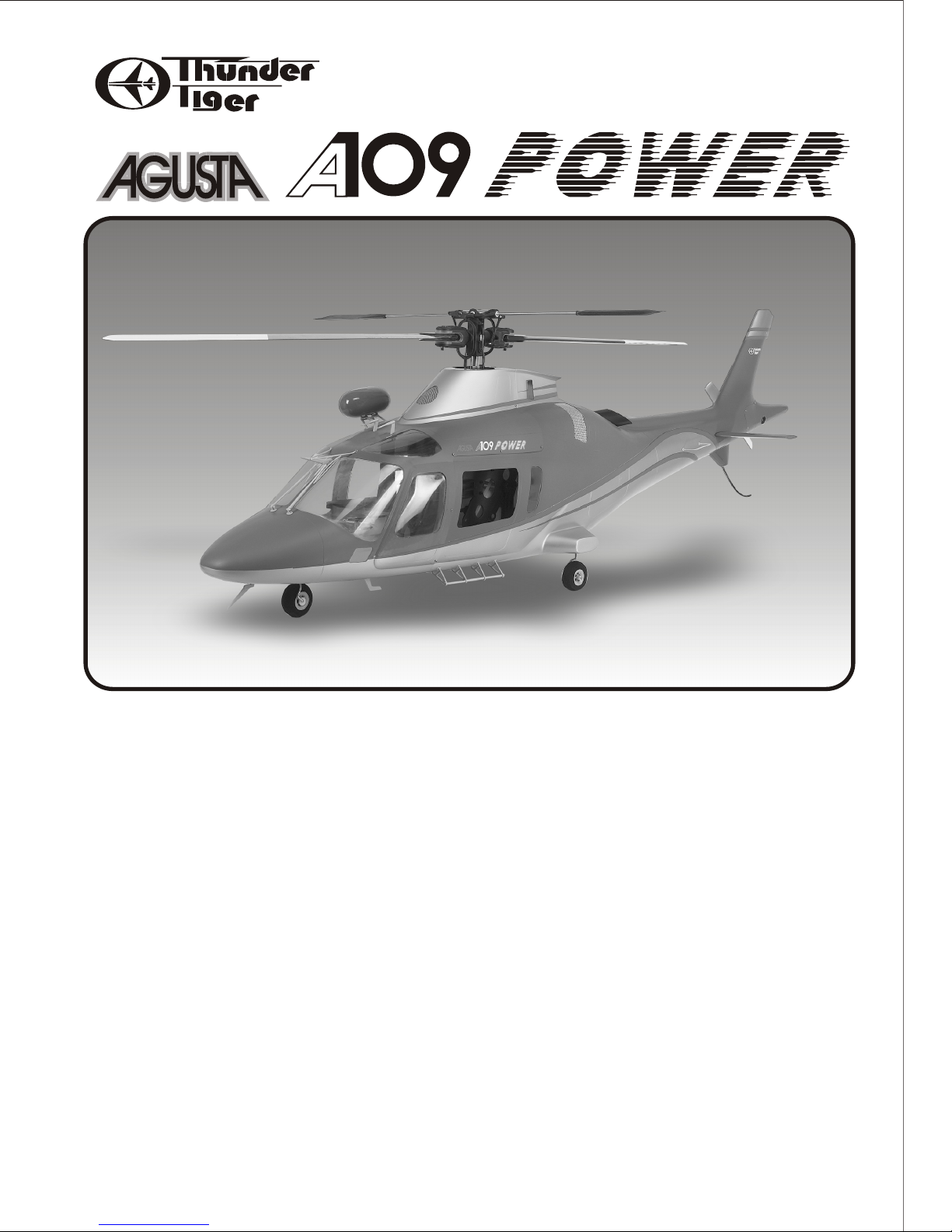
No.3842
No.3842-W
Assembly Manual
Specifications:
Fuselage Length (less rotor): 65.4" (1660mm)
Fuselage Width (less rotor): 14.2"(360mm)
Fuselage Height: 13.4"(340mm)
Full-Equipped Weight: 14.2 lbs(6450g)
1
Page 2
Before beginning the assembly read the instructions thoroughly to give an understanding of the sequence of steps and a
general awareness of the recommended assembly procedures.
By following these instructions carefully and referring to the corresponding pictures, the assembly of your model will be
both enjoyable and rewarding. The result will be a well built, easy to assemble scale model, which you will be proud to
display.
This A109 is designed for intermediate to advanced pilots, and this manual assumes a basic knowledge of R/C model
construction.
PRE-ASSEMBLY NOTES
1. Before you start to assemble this fuselage on your helicopter, we suggest you to first fine tune your helicopter in the air.
2. Double-check all screws, then secure and Loctite all the loose screws.
3. The instruction manual is written for Raptor 90, if user should choose to install it on other branded helicopters, we would
suggest you to study the manual thoroughly and see how it installed on a Raptor 90.
Before you begin, check the entire contents of your kit against the parts list and photos to make sure that no parts are
missing or damaged. This will also help you to become familiar with each component of your model. If you find that any of
the parts are either missing or damaged, please contact your local Thunder Tiger authorized distributors for replacements.
Neither your dealer nor Thunder Tiger authorized distributor can accept kits for return if construction has begun.
Trial fit each part before gluing it in place. Make sure you are using the correct part and that it fits well before assembling.
BEFORE YOUR ASSEMBLY
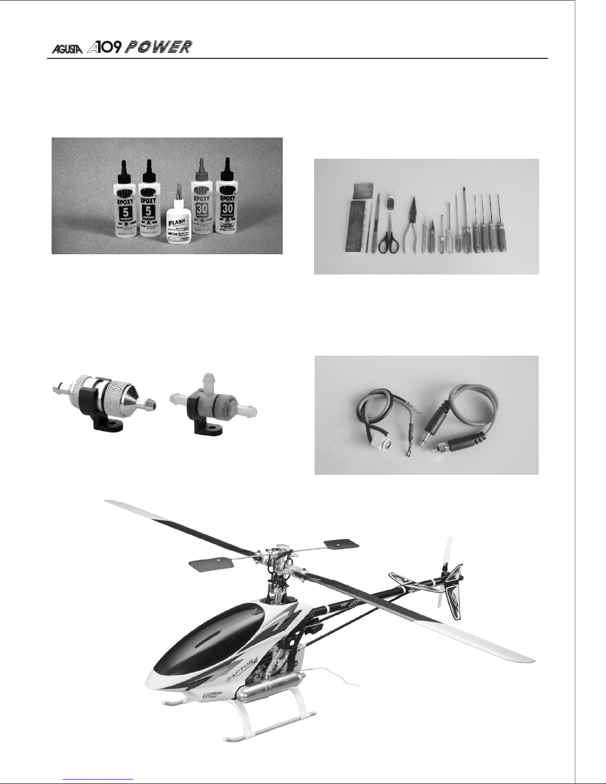
Adhesives:
Instant setting Cyanoacrylate adhesive (thin CA)
Slow setting Cyanoacrylate adhesive (thick CA)
10 Minute Epoxy (fast)20~30 Minute Epoxy(slow)
RECOMMENDED TOOLS & MATERIALS
R/C System:
6 Channel Heli radio req'd
GYRO system req'd
Helicopter:
Raptor 90 SE kit Suggested
You will need two types of adhesives for the A109 Epoxy
and Instant (cyanoacrylate) adhesives. We recommend
that you purchase both 5-minute and 30-minute epoxy to
cut down on assembly time, but you can get by with only
30-minute epoxy if time is not important. You will also
need a small bottle of both "Thick" and "Thin" instant CA
adhesive.
ITEMS YOU MAY NEED
TABLE OF CONTENTS
Introduction....................................................................................................................................................2
Recommended Tools & Materials......................................................................................................................3
Item You May Need..........................................................................................................................................3
Parts Drawings.............................................................................................................................................4-5
Parts Check List..............................................................................................................................................6
Assembly...................................................................................................................................................7-15
MEMO..........................................................................................................................................................16
TTR4891 - Raptor 90 SE KIT
TTR1111 - 3-way Fuel Filter
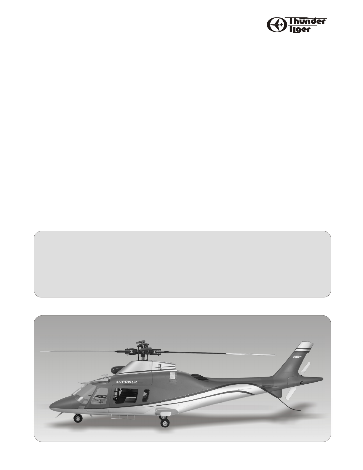
Congratulations on the purchase of our finest scale heli fuselage to date. This famous A109 fits Thunder Tiger Raptor 90,
the light fuselage comes factory pre-painted with all necessary hardware. It is very easy to assemble and only takes you
few hours of enjoyable installation to put this scale body on your helicopter. This replica A109 is just like a real thing,
hovering this 109 that will definitely make you stand out on the flying field.
TTR1112 - AL. Fuel Filter
INTRODUCTION
Page 3
Adhesives:
Instant setting Cyanoacrylate adhesive (thin CA)
Slow setting Cyanoacrylate adhesive (thick CA)
10 Minute Epoxy (fast)20~30 Minute Epoxy(slow)
RECOMMENDED TOOLS & MATERIALS
Tools:
Model Knife, 1/2" MASK Tape, Small & Medium Screwdrivers, Scissors, Long nose Pliers, Drill and Drill Bits
(1/8", 5/64"), 150 Grid Sand Paper, Rat Tail and halfround file, Fine Felt Tip Pen & Soft Lead Pencil, Reamer,
Hex Wrenches.
R/C System:
6 Channel Heli radio req'd
GYRO system req'd
Helicopter:
Raptor 90 SE kit Suggested
You will need two types of adhesives for the A109 Epoxy
and Instant (cyanoacrylate) adhesives. We recommend
that you purchase both 5-minute and 30-minute epoxy to
cut down on assembly time, but you can get by with only
30-minute epoxy if time is not important. You will also
need a small bottle of both "Thick" and "Thin" instant CA
adhesive.
Model assembly can be much easier if the proper tools
are used. Therefore, we have included in our checklist
to the left, a complete listing of all the tools we used to
assemble our prototype models. As you will notice,
many household tools can be utilized during
construction.
ITEMS YOU MAY NEED
TTR4891 - Raptor 90 SE KIT
TTR1111 - 3-way Fuel Filter
32
TTR1112 - AL. Fuel Filter
Ignition Extension.
PRE-ASSEMBLY NOTES
Page 4
3X25mm
Setscrew(2)
PV6026 Hardware
Front Fuselage(1)
Rear Fuselage(1)
Tie Band(2)
POM Washer(6)
2X5mm
Wood Screw(23)
4X60mm Muffler Bolt(2)
Exhaust Pipe(2)
Screen (S/1)
Muffler extension(1)
Tail End(1)
Silicon Tube(1)
Tail Boom
Foam Retainer(1)
Screen (L/2)
Horizontal Tail(2)
Tail Skid(1)
Wind Shield(L/1,R/1)
Middle
Window(L/1,R/1)
Sun Roof (L/1,R/1)
Front
Window(L/1,R/1)
Rear
Window(L/1,R/1)
Front Lower
Window(L/1,R/1)
PV6034 Windshield
Rod End (2)
Carbon Rod(1)
PV6028 Retaining Set
Post(2)
Body Retainer(L/2,R/2)
Lower Wire
PV6027 Decoration Set
PV6030 Retract MNT&Linkage
PV6029 Retract Gear
Wheel(3) Retract (3)
PV6031 Integrated Wood MNT
M3 Lock Nut (8)
Sokcet Screw 3X10mm(8)
Sokcet Screw 3X8mm(4)
M3 Washer (12)
PV6033 Fuselage
(PV6033-W)
PV6032 Horizontal Tail
(PV6032-W)
PARTS DRAWINGS PARTS DRAWINGS
Page 5
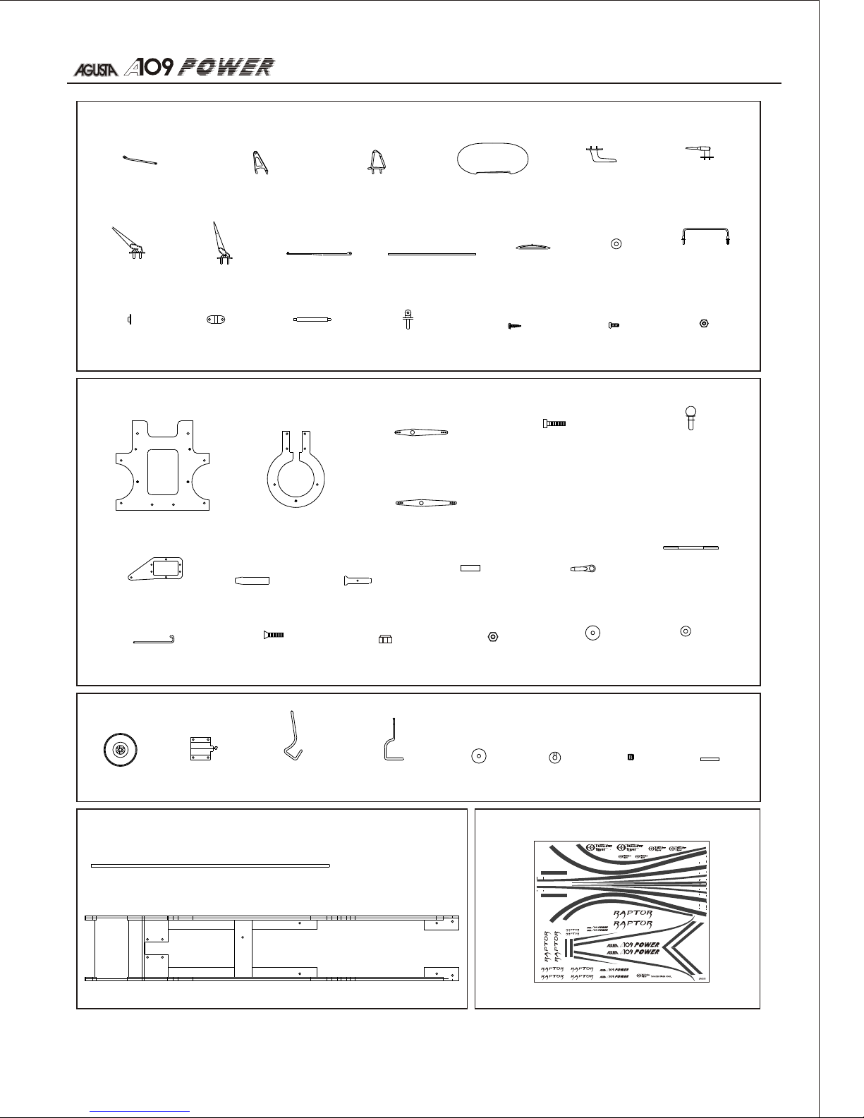
Carbon Rod (1)
Wire Strike
Strut(L/1,R/1)
Foot Step
Support (4)
Lower
Antenna(2)
Upper
Antenna(2)
Lower Wire
Strike(1)
Upper Wire
Strike(1)
Wiper (2)
Wiper Base (2)
Foot Step (1)
Handle Rail(2)
Cap(2)
PV6027 Decoration Set
PV6030 Retract MNT&Linkage
PV6029 Retract Gear
Wheel(3) Retract (3)
Nose Landing
Gear(1)
Main Landing
Gear(2)
POM
Washer(3)
Collar(3) Setscrew(3)
PV6031 Integrated Wood MNT
Decal(1)
Mounting
Strip(2)
PV6035 Decal
Socket Screw
3X6mm(3)
3X12mm(10)
3X20mm(1)
3X25mm(6)
3X35mm(4)
Hoist (1)
Hoist
MNT Rod (4)
Wiper
Mount (2)
2x6mm
Self-Tapping Screw (4)
2x6mm
Screw (4)
M2 Nut (4)
Retaining
Collar (32)
Main Plate(1) Retract Mount (2)
Front Horn(1)
Rear Horn(1)
M3 Washer(9)3X10mm Sink
Head Screw(12)
M3 Locknut(30)
Servo Tray(1)
30mm (2)
60mm (1)
45mm (1)
Coupler (2)
Servo Mount
Standoff (2)
Z-Bend Pushrod (2)
Standoff (2)
Ball End (8)
Standoff Ball
8mm(3)
10mm(2)
12mm(2)
18mm(1)
Wood Mount (1)
Hoist MNT (2)
POM
Washer(2)
Threaded Rod
Wheel
Spacer(3)
M2 Nut(8)
54
(only comes with No.3842 )
Page 6

1. Get your Raptor 90 well tuned before you install the
body. Remove the tail transmission, landing skid and
rotor head.
2. Locate the landing gear includes retracts, wires,
wheels, collars, POM washers, wheel spacers and
setscrews.
3. Secure the main retract wire with the setscrew which
is already in the retract shaft. Adjust the wire at 50mm
(1-31/32") in length then insert POM washer, wheel
then secure the collar with setscrew.
Front Fuselage (1)
Rear Fuselage (1)
Tail End (1)
Exhaust Pipe (2)
Horizontal Tail (2)
Wind Shied (L/1,R/1)
Middle Window (L/1,R/1)
Sun Roof (L/1,R/1)
Front Window (L/1,R/1)
Rear window (L/1,R/1)
Front Lower Window (L/1,R/1)
Pos t(2)
Rod End (2)
Carbon Rod (1)
Body Retainer (L/1,R/1)
M3 Lock Nut (8)
M3 Washer (12)
Sokcet Screw 3X8mm(4)
Socket Screw 3X10mm(8)
Wheel (3)
Retract (3)
Nose Landing Gear (1)
Main Landing Gear (2)
POM Washer (3)
Collar (3)
Setscrew (3)
Wheel Spacer (3)
Main Plate (1)
Retract Mount (2)
Front Horn (1)
Rear Horn (1)
Socket Screw 3X6mm(3)
Socket Screw 3X12mm(10)
Socket Screw 3X20mm(1)
Socket Screw 3X25mm(6)
Socket Screw 3X35mm(4)
Standoff Ball 8mm(3)
Standoff Ball 10mm(2)
Standoff Ball 12mm(2)
Standoff Ball 18mm(1)
Threaded Rod 30mm(2)
Threaded Rod 45mm(1)
Threaded Rod 60mm(1)
Servo Tray (1)
Coupler (2)
Standoff (2)
Ball End (8)
Z-Bend Pushrod (2)
3X10mm SinK Head Screw (12)
M3 Locknut (30)
M2 Nut (8)
POM Washer (2)
M3 Washer (9)
Carbon Rod (1)
Wood Mount (1)
Decal (1)
Wire Strike Strut (L/1,R/1)
Foot Step Support (4)
Hoist MNT (2)
Hoist(1)
Lower Antenna (2)
Upper Antenna (2)
Lower Wier Strike (1)
Upper wire Strike (1)
Wiper Base (2)
Foot Step (1)
Wiper (2)
Retaining Collar (32)
Handle Rail (2)
Cap (2)
Mounting Strip (2)
Hoist MNT Rod (4)
Wiper Mount (2)
2X6mm Self-Tapping Screw (4)
2X6mm Screw (4)
M2 Nut (4)
Silicon Tube (1)
Tail Boom Foam Retainer (1)
Tie Band (1)
Screen (S/1)
Screen (L/2)
2X5mm Wood Screw (23)
3X25mm Setscrew (2)
Muffler Extension (1)
4X60mm Muffler Bolt (2)
Tail Skid (1)
POM Washer (6)
Kit Contents
Fuselage
Horizontal Tail
Windshield
Retaining Set
Retract Gear
Decoration set
Hardware
Retract MNT&Linkage
Integrated Wood MNT
Decal
PARTS CHECK LIST
Page 7

1. Get your Raptor 90 well tuned before you install the
body. Remove the tail transmission, landing skid and
rotor head.
2. Locate the landing gear includes retracts, wires,
wheels, collars, POM washers, wheel spacers and
setscrews.
3. Secure the main retract wire with the setscrew which
is already in the retract shaft. Adjust the wire at 50mm
(1-31/32") in length then insert POM washer, wheel
then secure the collar with setscrew.
4. Same way to assemble the nose gear and adjust the
wire at 65mm( 2-1/2 ") in length.
5.Locate the main plate, retract mount, servo tray, M3
locknuts, standoff, 3x12mm and 3x25mm socket
screws as shown in the photo.
6.Secure the retract mount and the servo tray on the
main plate. Next locate retract gear, 3x10mm sink head
screw, M3 locknut, retract servo, 3x12mm socket
screw, M3 locknut and washer as shown.
76
Page 8

7. Install the retract gear on main plate as well as the
retract servo, note the servo orientation. Locate the
two 12mm standoff-balls for retract pushrod; 8 and
10mm standoff-balls, standoff, 3x6mm socket screws
and POM washer for rear horn. Note the rear horn is
longer than front horn.
8. Install the balls and rear horn in place properly.
Secure the M2 Nut on all balls. Note the 10mm standoff
-ball should be installed at the short arm side.
9.Locate the Z-bend pushrod and 45mm threaded rod
then thread the ball ends. Measure at two ball ends at
about 75mm.
10. Get a disc horn then drill two 2mm hole ( 9.5mm to
the center) as photo shown. Drill another 1.5mm hole
(16mm to the center) then secure the 10mm standoff ball with M2 nut.
11.Install the pushrods as photo shown and adjust the
ball end to get a good movement.
12. Same way to install the front horn in place with 3x6
and 20mm socket screw, M3 washer and POM washer,
two 8mm standoff- balls. Install the nose gear in place
with 3x10mm sink head screws, M3 washer and
locknuts. Secure the 18mm standoff-balls on the nose
gear pushrod with M2 nut.
13. Assemble the pushrods; one is about 95mm between
two center points of ball end, the other is about 465mm
of two ball end center.
14. Temporally install the retract assembly on the
wood mount then install the pushrods to link the front
and rear horn as well as the nose gear pushrod. Test
the retract gear and adjust the pushrods until it works
perfectly.
Note: Do not over tighten the standoff ball on the
retract link as it may break the plastic. Just tight
and use Loctite.
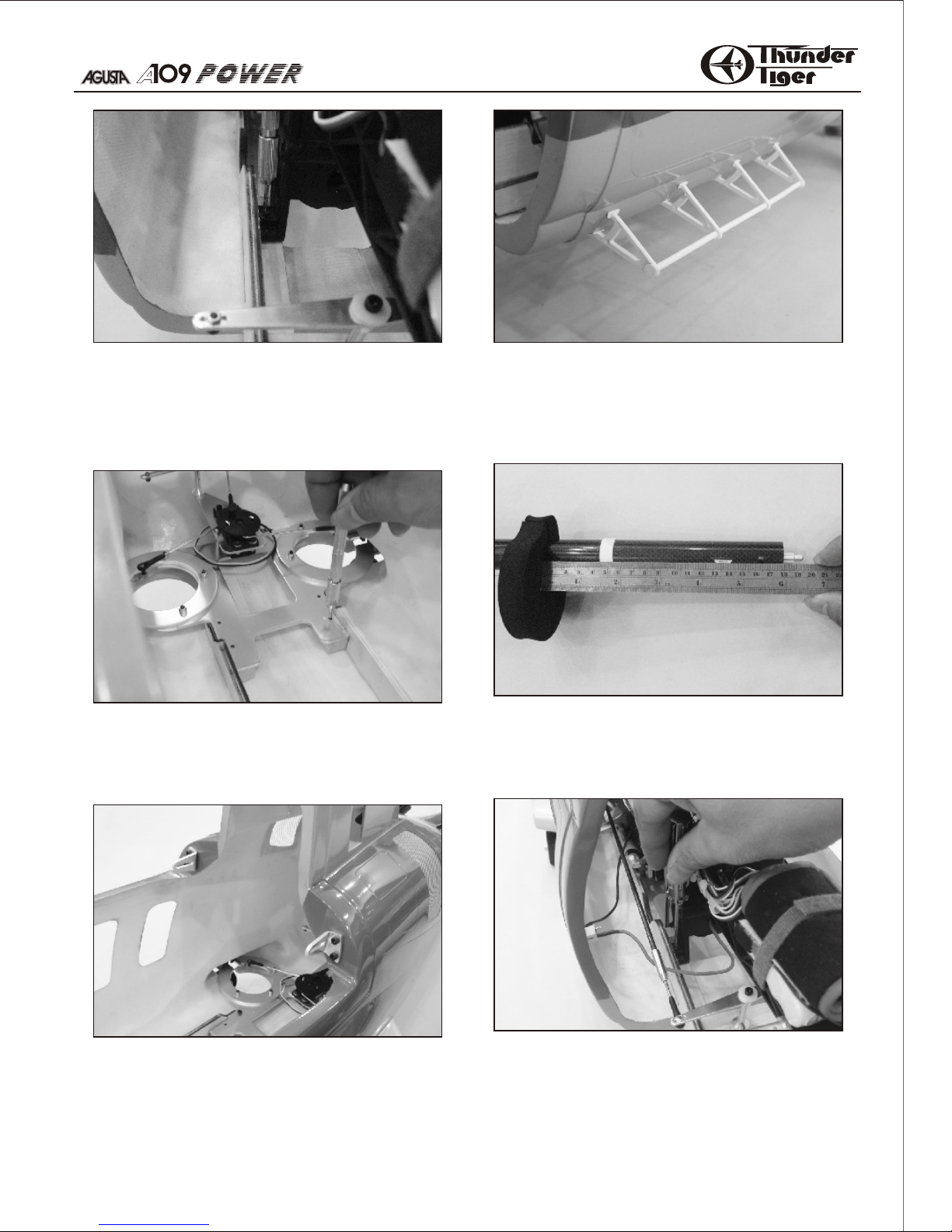
15. Epoxy the two pieces of screen and exhaust pipes in
place.
Page 9

13. Assemble the pushrods; one is about 95mm between
two center points of ball end, the other is about 465mm
of two ball end center.
14. Temporally install the retract assembly on the
wood mount then install the pushrods to link the front
and rear horn as well as the nose gear pushrod. Test
the retract gear and adjust the pushrods until it works
perfectly.
15. Epoxy the two pieces of screen and exhaust pipes in
place.
16. Install the handle rail at the tail, it is about 27cm
from the end. Drill 2mm holes and press plastic collar
to secure it in place. Apply tiny CA at the contact area
of handle rail and fuselage.
17. Remove the retract assembly from wood mount.
Next remove one side of retract from main plate so it
could be placed in the retract area of the fuselage.
18. Install the retract you just removed from the main
plate as shown.
98
Page 10

19. Place the wood mount and join the main plate, next
center the wood mount then make marks on fuselage.
20. Remove the wood mount, then use file to make two
notches so the wood rails can fit in later.
21. Install the muffler and check if muffler contacts the
wood mount. You may need to trim the wood mount.
(photos shown is OS91 with ) The
kits comes with muffler extension that you may use.
Check if the throttle lever contacts the muffler if you
use the extension. Trim the contact area if necessary.
Zimmermn muffler
22. CA the main plate and wood mount in place and
make sure the holes on main plate are aimed to the
holes on wood mount.
23. Temporally secure the helicopter on wood mount
with a M3 socket screw, this is to keep helicopter and
wood mount together for next assembly step.
24. Replace the post from the old one. Next install the
body retainer with 3x8mm socket screw and washer.
Adjust the body retainer so it just contact the fuselage.
Make marks at the holes. Do the same procedure at the
other side.
25. Make sure the helicopter and retract are well
positioned. Carefully remove the socket screw, next
use the hole as drilling guide then drill a pilot hole.
Next enlarge the hole to 3mm.
26. Temporally secure the wood mount at the hole you
drew in the last step. Next using the four holes on main
plate as drilling guide then drill pilot holes. Enlarge the
hole to 3mm.
27. Drill 3mm holes at the marks, secure the retainer
with 3x10mm socket screw with M3 washers and
locknut. Secure the wood mount and main plate with
two 3x25mm Socket Screw, POM washer and M3 nut at
far-most two holes.
Page 11
25. Make sure the helicopter and retract are well
positioned. Carefully remove the socket screw, next
use the hole as drilling guide then drill a pilot hole.
Next enlarge the hole to 3mm.
26. Temporally secure the wood mount at the hole you
drew in the last step. Next using the four holes on main
plate as drilling guide then drill pilot holes. Enlarge the
hole to 3mm.
27. Drill 3mm holes at the marks, secure the retainer
with 3x10mm socket screw with M3 washers and
locknut. Secure the wood mount and main plate with
two 3x25mm Socket Screw, POM washer and M3 nut at
far-most two holes.
28. Locate foot step accessories then use care to
install the foot step support on the fuselage, make sure
they are level with each other. Press the retaining
collar firmly then apply CA at the last.
29. Locate the tail boom foam retainer, measure at
18cm(7") from the boom end. Secure foam retainer in
place with CA.
30. Before you install the helicopter into fuselage, get
an extension wire for retract servo. Carefully install the
helicopter in the fuselage, pull the tail boom and
position the helicopter in place properly. Secure the
helicopter with 3x35mm socket screw, POM washer
and M3 Locknut.
1110
Page 12

31. Install the ignition extension outlet on fuselage.
32. Drill about 14mm(5-1/2”) hole at the bottom fuselage
where is 35mm (1-3/8”) away from the panel line. Get
the silicone tube exit at the hole.
33. Assemble the carbon rod with two rod ends. Next
install the other two body retainers and carbon rod with
two 3x8mm, four 3x10mm socket screws, M3 washers
and locknuts.
34. Drill 3mm hole at the bottom fin of leading edge then
epoxy the tail skid inside the fin about 36mm(2-1/2”).
35. Locate 3x25mm setscrews then install on horizontal
tail. Apply epoxy inside the hole and thread the
setscrew in the tail and leave about 10mm in length
outside the tail.
36. Drill a hole to accommodate the setscrew on tail.
Trial fit the tail in place, lightly sand the glue area then
epoxy the tails in place firmly.
37. Install the tail transmission and link in place. Make
sure it works properly.
38. Cut tail end into two pieces as shown. Use the
template in page 15, cut the template off and apply on
tail end then trim off the area.
39. Install the tail in place and trim the contact areas
with tail transmission.
Page 13

37. Install the tail transmission and link in place. Make
sure it works properly.
38. Cut tail end into two pieces as shown. Use the
template in page 15, cut the template off and apply on
tail end then trim off the area.
40. Secure the tail end with 2x5mm wood screws.
41. Trim all windshield and windows. Both sand the
glue area to enhance the adhesion. You may skip
installing the middle windows for easy access and
tuning the helicopter. This also help the cooling.
39. Install the tail in place and trim the contact areas
with tail transmission.
42. Epoxy the small screen inside the front fuselage as
shown.
28mm
63mm
147mm
1312
40mm
Page 14
43. Locate the wiper and upper wire strike as well as its
relative hardware.
44. Install the wipers, upper wire strike and antennas
in front of the windshield as photo shown.
46. Assemble the external hoist mount first then secure
the hoist on the mount with the mounting strip and four
2x6mm self-tapping.
48. Trim all windows and both sand the glue area on
windowsand fuselage. Epoxy the windows in place
properly. You mayskip installing the middle window for
engine adjustment and any maintenance of helicopter.
50. Cut the front fuselage then join the front fuselage to
the rear fuselage with 16 pieces of 2x5mm wood screws.
45. Install the lower antennas as well as the lower wire
strike.
47. Next install the hoist assembly on the fuselage as
photo shown.
49. Install the rotor head back to the helicopter, make
sure all links are well connected and servos work fine.
Page 15

50. Cut the front fuselage then join the front fuselage to
the rear fuselage with 16 pieces of 2x5mm wood screws.
Congratulations! Now you are finished the assembly of
this beautiful scale body.
1.When hovering your 109, try to keep your rotor speed
at approximately 1500 RPM.
2.Check the helicopter and fuselage to see if any screw
loosened after each flight.
3.Trim the elevator or rudder when switching on the idle
when you process the speed flight if necessary.
49. Install the rotor head back to the helicopter, make
sure all links are well connected and servos work fine.
Template for Tail End Opening
1514
Page 16

This kit is guaranteed to be free from defects in material and workmanship at the date of purchase.
It does not cover any damage caused by use or modification. The warranty does not extend
beyond the product itself and is limited only to the original cost of the kit. By the act of building this
user-assembled kit, the user accepts all resulting in liability for damage caused by the final
product. If the buyer is not prepared to accept this liability, it can be returned new and unused to
the place of purchase for a refund.
This is not a toy. Assembly and flying of this product requires adult supervision.
Read through this book completely and become familiar with the assembly and flight of this A109.
Inspect all parts for completeness and damage. Browse www.thundertiger.com for customer
service if you encounter any problems.
MEMO
16
Assembly Manual
 Loading...