

Page 1
Please read all instructions thoroughly before operation.
For fresh water use only.
Thunder Tiger Corporation guarantees this model kit to be free from defects in both material and workmanship. The
total monetary value under warranty will in no case exceed the cost of the original kit purchased. This warranty does
not cover any components damaged by use or modification. Part or parts missing from this model must be reported
within 60 days of purchase. No part or parts will be sent under warranty without proof of purchase. To receive part or
parts under warranty, the service center must receive a proof of purchase and/or the defective part or parts. Should
you find a defective or missing part, contact the authorized Thunder Tiger Service/Distributor nearest you. Under no
circumstances can a dealer or distributor accept return if assembly has started.
No.5222-F
The contents are subject to change without prior notice due to product improvements and specification changes.
Page 2
Thank you for your purchase of the TTR Seawolf submarine. The Seawolf submarine is the 1st
underwater R/C model by TTR. Equipped with high technology operating system in the inner hull
tube, covered by bright orange color outer hull, the Seawolf will let you enjoy the underwater
world.
With static diving system, operating the Seawolf submarine is just like the real thing. The system
equip with a ballast tank that comes with a pump unit. Start the pump to induct the water into the
ballast tank. Control the amount of water into the ballast tank, the Seawolf submarine can dive
from the surface and stay underwater in static. Using the propulsion power unit and full elevator
and rudder control, you can drive the Seawolf submarine gracefully into water. Install a digital
camera and you can watch the amazing underwater scenes.
Equipped with an auto protecting system, if the system detects low battery power, low transmission signal or leakage, the pump will start automatically to flood the water out of the ballast tank
to make the Seawolf submarine float back to the surface.
TTRobotix Seawolf submarine will take you to enjoy the mystery world under the water!
01
INTRODUCTION
ITEMS & TOOLS REQUIREMENT
IMPORTANT NOTES & WARNING
CONFIGURATION
RADIO CONTROL vs SUBMARINE MOVEMENT
INTRODUCTION FOR THE MAIN DEVICE
OPERATION
CHARGER CONNECTION
CUSTOMER SERVICE
EXPLODED VIEW
SPARE PARTS
SPARE PARTS LIST
01
02
02
03
04
05
06
09
09
10
13
17
INTRODUCTION
INDEX
Page 3
IMPORTANT NOTES & WARNING
One 4S LiFe battery is included to supply the requiring power for all the electric equipment and drive system. DO NOT leave the charger unattended, DO NOT operate the
charging process in flammable environment.
1. This radio control submarine is not a toy. If not properly assembled and operated, it is
capable of causing property damage. TTRobotix and it’s distributor have no control
over damage resulting from shipping, improper construction, or improper usage.
2. You must choose the suitable and safet area to operate the submarine. It is dangerous
to drop the Seawolf into water.
02
1. To turn radio on, turn on the transmitter and extend the transmitter antenna first.
2. Then turn on the receiver (The switch is located at the bottom of the front flange unit).
When turning off, first turn the receiver off, then the transmitter.
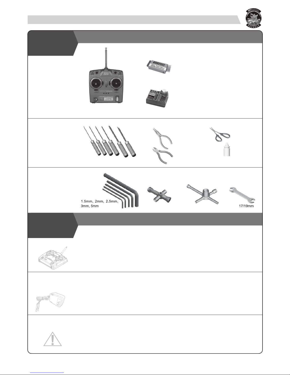
ITEMS & TOOLS REQUIREMENT
RADIO SET
TOOLS
NEEDED FOR
ASSEMBLY
TOOLS
INCLUDED IN
KIT
Needle Nose Pliers
Wire Cutter
Phillips type screwdrivers & hex wrenches
Thread Locking Glue
Lexan Cutter/
Scissors
Hex Wrench
4-way Cross Wrench
5-way Nut Wrench
Wrench
BATTERY
CHARGING
RADIO
WARNING
8603S
Seawolf Commander For 75MHz
For 40MHz
Page 4
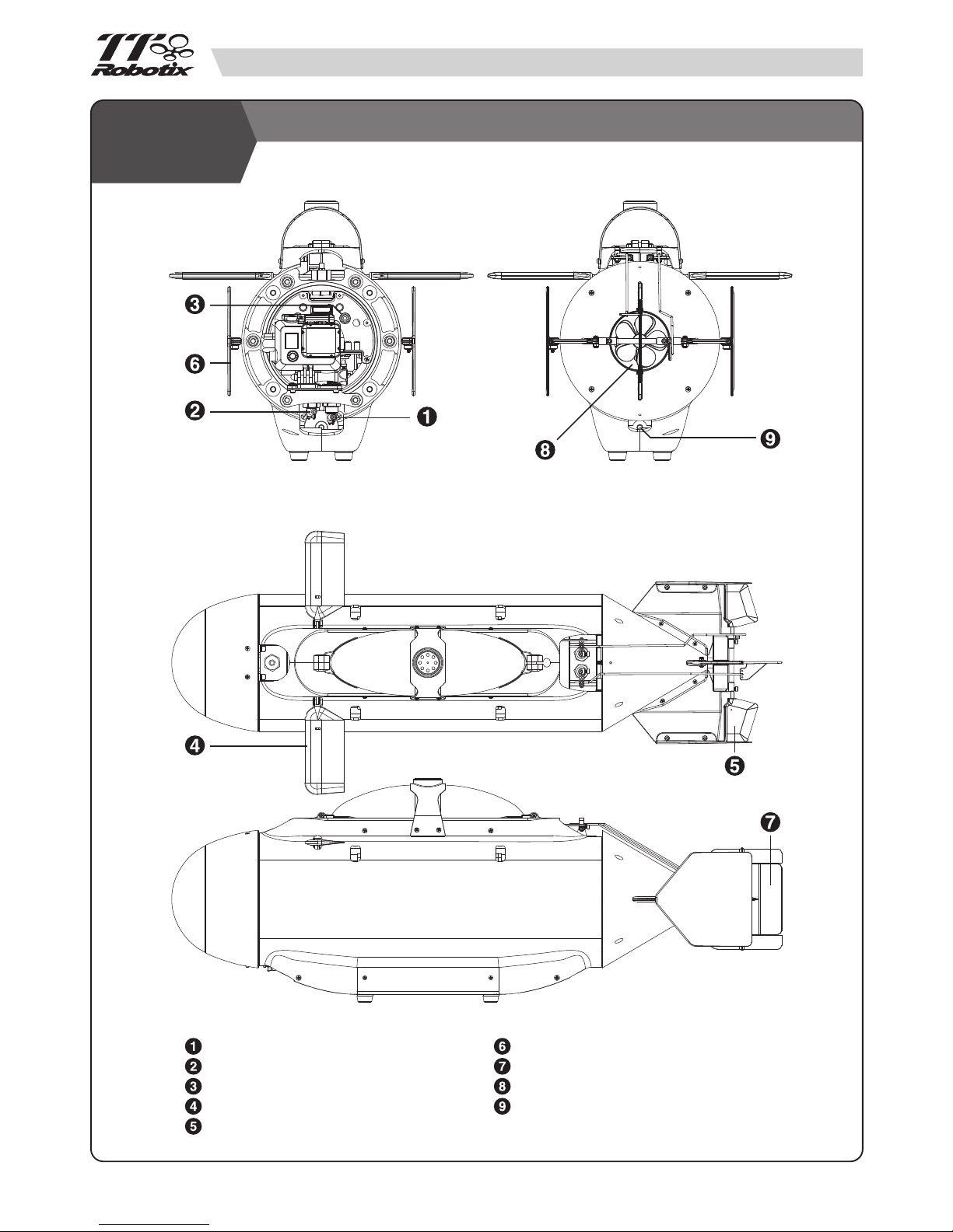
03
Switch-Power On
Switch-Not in Used
Charging Plug
Front Elevator
Rear Elevator
Verticle Stabilizer
Rudder
Propeller
Water Inlet/Outlet hole
CONFIGURATION
Page 5
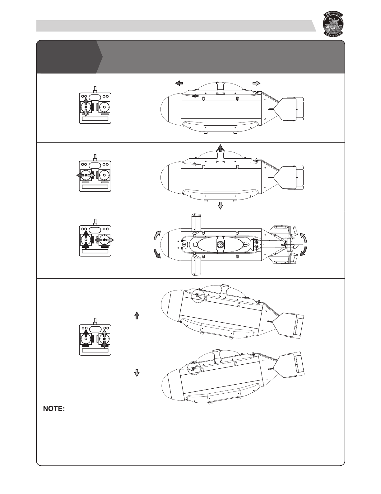
1) The radio show in the drawing is similar to Mode 2 of RC airplanes: throttle is at the left stick and elevator is at
the right one. However, the stick radio easily allows to shift to Mode 1. Open the inner hull and exchange the
servo connectors at the receiver.
2) Due to it’s more difficult for the RF signal through the water(especially in sea water). The control distance is
much shorter than the radio system operating on the surface.
04
RADIO CONTROL vs SUBMARINE
MOVEMENT
Forward
Throttle
Floating / Diving
Steering
(Forward)
Elevator
(Forward)
Backward
Right turn
Left turn
Nose up
Nose down
Note: Drive of water pump.
Draw water for diving.
Drain water for floating.
Page 6
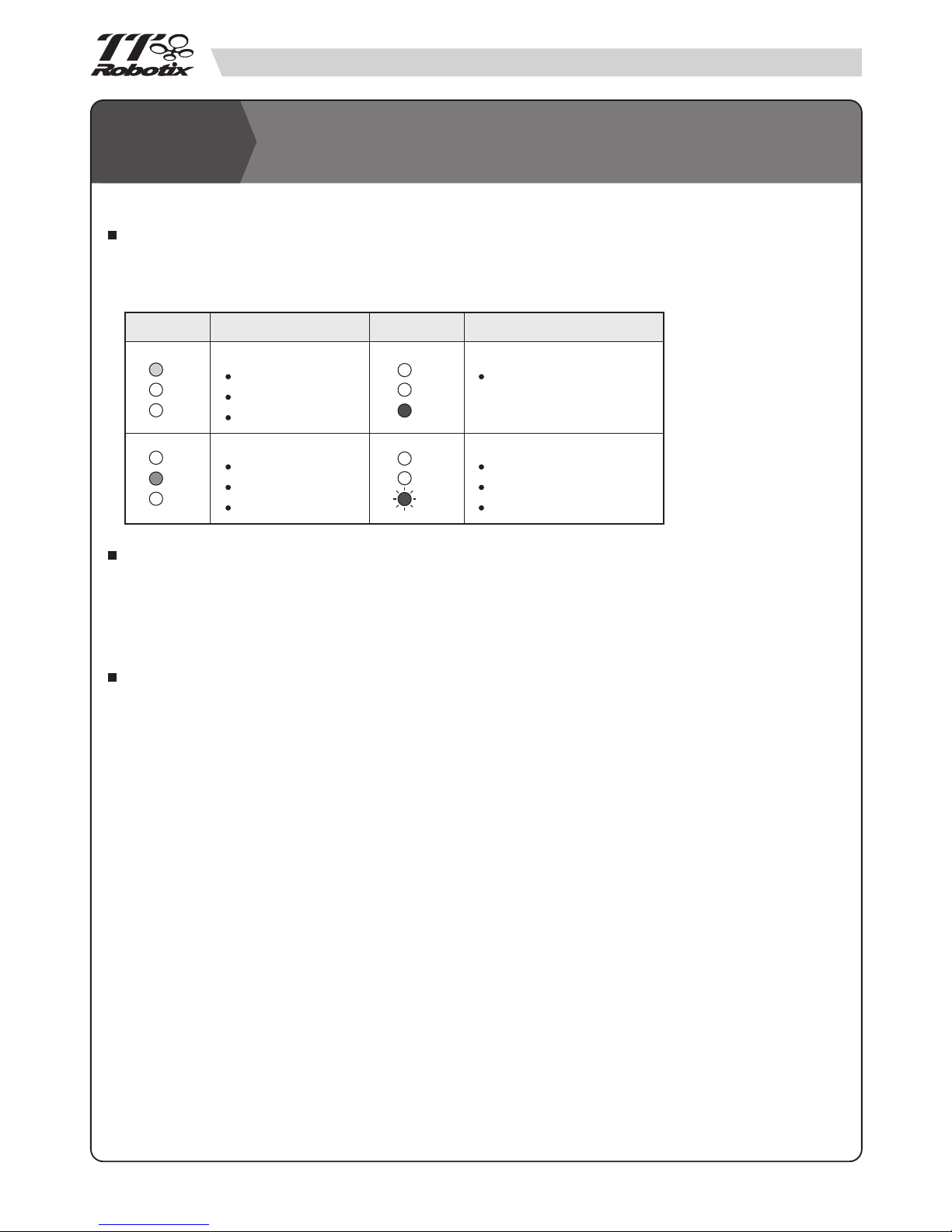
LED INDICATION LIGHT
On the main control PCB unit, there are 3 LED lights are designed to show the current status of the Seawolf
submarine. You can observe the light and refer to the following chart to get the light information.
AUTO PROTECTING SYSTEM
Combined with a auto protecting system on the main PCB control board, if the system detects low battery power,
low transmission signal, leakage(water inside hull), then the roll pump will auto start to flood the water out of the
ballast tank to make the submarine float back to the surface. At the same time, the Red LED light will flash.
PUMP WITH BALLAST FOR THE STATIC DIVING SYSTEM
Red Light On (Continuous)
Normal Operating
05
Light Sign Light SignSeawolf Status Seawolf Status
Base on the Archimedes principle—principle that states a body immersed in a fluid is buoyed up by a force equal
to the weight of the displaced fluid. The principle applies to both floating and submerged bodies.
So base on this principle, equipped with a roll pump with ballast tank device in the inner hull, through the pump
operating system to draw or drain the water into or out of the ballast tank to change the weight of the submarine.
With suitable design of the volume and weight, then it is easy to operate the Seawolf diving or floating and even
static stay under the water. So we call this the static diving system just like the real submarine.
The buoyancy of an object depends, therefore, only upon two factors: the object's volume, and the density of
the surrounding fluid. So when you choose the diffierence water(with diffierence density) to play, you have to readjust the weight unit to make the submarine can be diving and floating smoothly and quickly. Normally, it need take
about 50 seconds from floating to diving.
INTRODUCTION FOR THE MAIN
DEVICE
Low Battery
Tx Signal Lost
Water Inside Hull
Red Light Flash
(Y)
(G)
(R)
(Y)
(G)
(R)
(Y)
(G)
(R)
(Y)
(G)
(R)
Water Pump On
Ballast Bag Filling
Diving
Water Pump On
Ballast Bag Emptied
Surface
Yellow Light On--
Green Light On--
Page 7

06
Switch on the transmitter. Check again TX battery status.
Switch on the receiver (main switch). Check no interference from any other RC transmitter
If the submarine doesn’t switch on, check the fuse and replace if necessary.
Check that the front hood is perfectly installed. If it isn’t, any hit during the launch will cause it to fall down
into the water. It will sink, being heavier that the water.
Start the pump and empty the bag (left stick to right), until the bag is totally emptied. This will be shown
by the changed noise and the absence of air coming out from the water intake.
PRE-LAUNCH CHECK
POWER SWITCH
Power Switch
The main power switch is located at the bottom of the front
flange. From the bottom view, the left switch is to control the
main battery power for all the electric devices. The right switch
is unused.
For fresh water use only.
Check if there is no water is inside the hull. If water is found inside the hull, the submarine shouldn’t be
used until you discover the cause of the problem and solve it.
Close the front cap and tighten the nuts (sequence: opposite nuts). After locking, the front O-Ring should
appear uniformly flattened against the cap.
Switch on the transmitter and check TX battery status.
Switch on the submarine and check the following functions:
Check throttle: move left stick up/down and verify that full forward and reverse speed is reached. In
centre position (idle) the propeller should not move. Correct TX trim if necessary
Check pump: move left stick right and left and verify that the pump starts running and inflates or empties
the ballast. You may hear the noise of the motor and also feel the pump action by placing a finger at the
water intake.
Check dive planes (right stick up/down). Verify that stick neutral position corresponds to horizontal dive
planes. Trim if necessary.
Check rudder (right stick left / right). Verify that stick neutral position corresponds to straight rudder. Trim
if necessary.
Switch off RX and TX respectively.
PREPARATION
NOTE: Pump action is on-off and it’s normal that it is not proportional. However, be sure that the
centre idle position of the stick is equally far from left and right working position.
Trim if necessary.
NOTE: If the fuse is burnt again, then should be a short circuit inside. Don’t use the model.
Open it and search for any electrical problem)
OPERATION
Please follow the following procedures to do the preparation.
Page 8

BUOYANCY CHECK & WEIGHT ADJUSTING
Before using the submarine for the first time, check its correct buoyancy.
Fill a bath tub with cold water and put the submarine into it
With the ballast bag completely empty, the submarine should float keeping the turret and a thin part of the
outer hull above the waterline. You can change the weight parts to get the suitable position.
Check if the submarine has a good trim, staying horizontal and without listing. If necessary adjust the ballast
in the submarine keel. And, adjust the position of the weight parts to make the submarine level without pitch
up or down.
Please remember that different water conditions (for example, bath tub, swimming pool or lake) have an
influence on the submarine trim due to different water density. Perform a buoyancy check any time you want
to use the submarine in new places.
RECOVERY
Start the pump in order to have the ballast bag completely empty
Pilot the sub along the side of the swimming pool or lake, in a reachable position.
Connect the hooks handle to the lifting points inside the slots of the hull. Be sure to clamp the inner metal rod
and not only the plastic hull.
Lift the submarine out of the water. During this phase, it will be significantly heavier, because of the water
trapped between inner and outer hulls. Then, this water will be discarded and the operation will be simpler.
Place the sub on a horizontal surface
Switch the submarine and the transmitter off.
Have a quick inspection of the hull and check no part has been damaged or lost.
Start piloting your Seawolf.
Find a good launch location, with the possibility to stand stable with no risk of falling into the water. The water
surface should be easily reachable and must not be too low. Becareful with tide.
Insert the handle into the holes of the external hull. Be sure that the hooks are connected to the metal rod of
the inner hull and not only to the outer plastics .
Lift the sub and gently place it into the water.
Wait until the front hood and the rear cone are totally full of water. These are free-flood compartments and it’s
normal they become totally full of water, no large air bubble should remain inside them.
At this point, disconnect the handle.
.
LAUNCH
07
NOTE: Pay attention not to let the handle fall into the water, it will sink!
OPERATION
Ballast empty 80% Ballast full 100% Ballast full
Page 9

All the controls are described above.
Rudder and throttle functions are similar to other R/C models.
This submarine is capable to perform both static and dynamic dive.
For a full static dive, keep the motor idle and start the pump flooding the bag. You will see the waterline at the
turret become higher and higher until the entire submarine will be submerged and will go down vertically to
the bottom. The opposite command will cause the pump to empty the ballast bag and the submarine will raise
to the surface.
Dynamic dive is possible thanks to the speed of the boat and the action of the dive planes. The ideal situation
is reached when only the top ring of the turret is out of the water: at this point, start the motor full forward and
set the dive planes to the “down” position: the submarine will dive and you will have dynamic control of the
depth by operating the dive planes.
Pay attention to any collision. If the submarine is running in a swimming pool or any other place with hard
vertical walls, avoid any hit with these hard structures. The front elerator and hood might be damaged or even
broken.
Also, be aware to avoid algae, leafs or any other seaweed that may jam the propeller. If leafs or other are
tangled around the propeller shaft, its efficiency will be greatly reduced and the stress on the motor will be
much higher. This situation should be avoided in order not to have critical damages on the propulsion system.
If the submarine raises to the surface on its own, it’s possible that some safety function has switched on. Take
the submarine out of water and check the alarm code from the LED indicator on the PCB.
If the submarine raises to surface because of low battery, you will discover much lower motor power and no
capability of diving. At this point, recover immediately the sub before the battery is completely empty (Please
remember that the receiver is BEC-equipped and the power source is the same also for the electronics!).
OPERATION
08
MANTEINANCE AND PERIODICAL
CHECK UP
Remove the outer hull panels and clean every part.
Before storing the submarine for a long time keep the inner hull open, disconnet the battery and fuse.
Check the pressure sensor (try to over fill the ballast bag).
Check the fail safe system (switch off the RC transmitter and see if the protection system activates).
Check the low battery safety system.
Check the integrity of inner hull. No cracks on inner tube.
Check there is no leakage from the inner linkages and tubing.
Check the dive planes and rudder operating angles. Adjust control rods and TX trims if necessary.
Check the O-Ring status and correct tightening.
Check operation of the switches and of all the other water proof exits. Devices must be tightened but must
retain a smooth movement.
OPERATION
Page 10

CHARGER CONNECTION STEPS
Remove the fuse. Keep it in a safe place.
Connect the charger to the AC power source.
Connect the charging cables and balance board to the charger as shown.
Connect Red Cable to Red Jack on the Seawolf.
Connect BLACK Cable to BLACK Jack on the Seawolf.
Connect the balance cable of the battery to the balance board.
The charger should begin to charge the battery. When charge is done, disconnect the cables in reverse order.
Tight the front panel screws diagonally in order to seal the hull properly with even pressure. The front O ring
should appear uniformly flattened against the cap or the electronics!).
09
CHARGER CONNECTION
BLACK REDBLACK RED
CAUTION! Always: BLACK cable to the BLACK port, RED cable to RED port.
CUSTOMER SERVICE
Distributed by / Vertrieb :
THUNDER TIGER EUROPE GmbH,
Rudolf-Diesel-Str. 1, 86453 Dasing, Germany
For customer service please contact
service@thundertiger-europe.com
Germany, Netherlands, Belgium,
Luxembourg, Austria, Italy
■
Distributed by :
Thunder Tiger Corporation
No.7 6th Road, Industry Park,
Taichung, Taiwan 40755
For customer service please contact
service@thundertiger.com
Tel : 886-4-23591632
For Other Countries
■
Page 11

External & Body Assembly
10
PJ6170
PD7808
PJ6413
PJ6405
PJ6124
PJ6408
PJ6409
PJ6410
PJ6133
PJ6161
PJ6162
PJ6161
PJ6162
PD0889-S
PD0889-S
PD0889-S
PD7811-S
PD0889-S
PD7811-S
PD7814
PD7814
PD7814
PD6419
PD7818
PD7818
PD7824
PD7818
PJ6413
PJ6410
PD0888-S
PJ6413
PD0889-S
*Camera and case are not included.
PJ6415
PJ6414
PJ6414
PJ6414
PJ6414
Page 12

PJ6406
PD0889-S
PJ6407
PJ6101
PJ6102
PJ6101
PJ6103
PJ6105
PJ6105
PJ6116
PJ6401
PJ6140
PJ6140
PJ6141
PJ6142
PJ6142
PJ6164
PJ6165
PJ6169
PJ6179
PD7801
PD7802
PD7803
PD7803
PD7803
PJ6142
PD7804
PD7804
PD7812
PD7813
PD7815
PD7816
PD7816
PD7816
PD7819
PD7820
PD7821
PD7823
PD7825
PD7826
PJ6401
PJ6156
PD1712
PJ6101
PJ6101
PJ6104
PJ6106
PJ6106
PJ6116
PJ6401
PJ6120
PJ6120
PJ6120
PJ6140
PJ6140
PJ6142
PJ6156
PJ6156
PJ6156
PJ6164
PJ6165
PJ6172
PJ6172
PJ6172
PJ6173
PJ6175
PJ6178
PJ6179
PD7801
PD7802
PD7805
PD7803
PD7804
PD7812
PD7815
PD7816
PD7820
PD7823
PD7825
PJ6401
Front Flange Unit Assembly Rear Cone Assembly
Front Cabin Assembly
Rear Flange Unit Assembly
PJ6412
PJ6412
PJ6411
PJ6411
PJ6155
PJ6155
PJ6411
PJ6411
PJ6413
PJ6411
PJ6416
PJ6412
PJ6412
11
Page 13

2853
BATTERY
PJ6402
PJ6402
PJ6402
PJ6403
PJ6403
PJ6403
8901
PJ6403
PJ6400
PJ6399
PJ6404
PJ6404
Inner Structure Assembly Drive System Assembly
Pump & Ballast Assembly
Outer Ring Frame Assembly
12
Page 14

SPARE PARTS
13
PJ6101 SEALED BOLT PJ6102 CONE RUBBER
PJ6103
SWITCH LINKAGE ROD
PJ6104 CONTROL LINKAGE ROD
PJ6105
WATER INLET BOLT SET
PJ6106
WATER PROOF BOLT SET
PJ6107 MOTOR SET,550 PJ6108 ROLL PUMP UNIT PJ6109 MOTOR MOUNT PJ6110 BALLAST TANK PJ6111
WATER TUBE CONNECTOR
PJ6114
DRIVE CUP&SHAFT SET
PJ6115 PROP DRIVE SHAFT PJ6116 FR/RR FLANGE
PJ6120 SWITCH MOUNT PLATE
PJ6123 RR COVER PLATE PJ6124 HULL MAIN TUBE PJ6133 TOP MARINE CANOPY
PJ6140 CONTROL ARM SET PJ6141 SERVO HORN&ROD PJ6142
LINKAGE ROD MOUNT
PJ6143 SCREW ROD(M6),L420 PJ6144 SCREW ROD(M4),L340 PJ6145 SCREW ROD(M4),
L240&L210
Page 15

SPARE PARTS
14
PJ6146 PLASTIC TUBE(6),L60 PJ6147 PLASTIC TUBE(10),L30
PJ6148 PLASTIC TUBE(8),L2&L6
PJ6149 ALUM. TUBE(4),L150 PJ6150 ALUM. TUBE(2),L101 PJ6151 ALUM. TUBE(4),L96
PJ6152 ALUM. TUBE(2),L41 PJ6153 ALUM. TUBE(2),L38 PJ6155
RR ELEV. MOUNT TUBE
PJ6156 HEX MOUNT BOLT PJ6157 WEIGHT MOUNT ROD PJ6159 WEIGHT/A,WT416G
PJ6160 WEIGHT/B(2),WT740G PJ6161 ORING(2),Ø124MM
PJ6162 ORING(2),Ø120MM
PJ6163 SEALED RUBBER/L(2) PJ6164 SEALED RUBBER/S(4) PJ6165 CONE RUBBER(20)
PJ6166
WATER TUBE,D6Xd3X300
PJ6167
WATER TUBE,D7Xd4X220
PJ6168 BOTTOM PLATE PJ6169 LINKAGE ROD SET PJ6170 HANDLE BAR PJ6173 BINDING POST
Page 16

SPARE PARTS
15
PJ6174 CONTROL PCB PJ6175
POWER DISTRIBUTION
BOARD
PJ6176 PRESSURE SENSOR PJ6177 LEAKAGE SENSOR PJ6179
WIRE CONNECT CABLE
PJ6183 WEIGHT(4),WT120G
PJ6399 PROPULSION MOTOR PJ6400
PROP. MOTOR MOUNT
PJ6401 SERVO&H.W MOUNT PJ6402 ROUND FRAME SET PJ6403
SEMI-ROUND FRAME SET
PJ6404 OUTER RING FRAME
PJ6405 FR COVER PLATE PJ6406 FR MARINE CANOPY
PJ6407 FR CABIN
PJ6408 OUTER HULL(L) PJ6409 OUTER HULL(R) PJ6410 TOP CABIN FRAME
PJ6411
RR RUDDER BRACKET
PJ6412 TAIL FIN SET PJ6413 RR CONE FRAME PJ6414
FR ELEVATOR BRACKET
PJ6415 FR ELEVATOR SET PJ6416 RR ELEVATOR SET
Page 17

SPARE PARTS
PJ6417
5 BLADE PROP.,D62x40
PJ6418 FUSE HOLDER PJ6419 CAMERA BRACKET PJ6420
BATT. CONNECT WIRE
PJ6421 WEIGHT/C(2),WT540G 2540S CHARGER,6S
2853 LIFE BATTERY,5000mAH 8091 ESC,BLC -25M 8175 STD SERVO/DS1903 8603S
SEA WOLF COMMANDER
O-RING(20) BT P. TAP SCREW
SET SCREWNUTLOCK NUTSPRING WASHERWASHER
PDS.K MACH. SCREWF.T P. MACH. SCREW,M3X8BT P. MACH. SCREWF.T P. MACH. SCREW NYLON STRAP(SMALL)
16
PD0975 Ø3 (20)
PD7478 Ø6 (20)
PD7819 Ø4 (20)
PD7820 Ø9.5 (20)
PD7821 Ø15 (20)
PD0889-S M3X10S (20)
PD1712-S M2.6X8S (20)
PD7809-S M2X8S (20)
PD7810-S M2X10S (20)
PD7811-S M3X12S (20)
PD7812-S M3X16S (20)
PD7801 M4X60S (4)
PD7802 M6X38S (12)
PD0884-S M3X8S (20)
PD0982 2.5 (20)
PD0877-S M3X8S (20)
PD0878-S M3X10S (20)
PD0879-S M3X12S (20)
PD7795-S M3X16S (20)
PD7803 M3X4S (20)
PD7804 M3X6S (20)
PD7805 M3X8S (20)
PD7806 M3X5S (20)
PD7817 Ø3S (20)
PD7818 Ø6S (20)
PD7830 Ø4S (20)
PD7816-S M3S (20)
PD7823 Ø4S (20)
PD7824 Ø6S (20)
PD7825 Ø10S (20)
PD7813 M4 (20)
PD7814 M6 (20)
PD7815 M10 (20)
PD0961 M3X3B(20)
PD7807 M3X3S(20)
PD7808 M3X4S(20)
For 75MHz
For 40MHz
Page 18

17
PART# DESCRIPTION NOTE
PD0982
PD1712-S
PD7478
PD7795-S
PD7801
PD7802
PD7803
PD7804
PD7805
PD7806
PD7807
PD7808
PD7809-S
PD7810-S
PD7811-S
PD7812-S
PD7813
PD7814
PD7815
PD7816-S
PD7817
PD7818
PD7819
PD7820
PD7821
PD7823
PD7824
PD7825
PD7830
2540S
2853
8091
8175
8603S
NYLON STRAP,2.5(SMALL,20)
BT P. TAP SCREW,M2.6X8S(20)
O-RING,Ø6(20)
BT P. MACH. SCREW,M3X16S(20)
F.T P. MACH. SCREW,M4X60S(4)
F.T P. MACH. SCREW,M6X38S(12)
PDS.K MACH. SCREW,M3X4S(20)
PDS.K MACH. SCREW,M3X6S(20)
PDS.K MACH. SCREW,M3X8S(20)
PDS.K MACH. SCREW,M3X5S(20)
SET SCREW,M3X3S(20)
SET SCREW,M3X4S(20)
BT P. TAP SCREW,M2X8S(20)
BT P. TAP SCREW,M2X10S(20)
BT P. TAP SCREW,M3X12S(20)
BT P. TAP SCREW,M3X16S(20)
NUT,M4(20)
NUT,M6(20)
NUT,M10(20)
LOCK NUT,M3S(20)
WASHER,Ø3S(20)
WASHER,Ø6S(20)
O-RING,Ø4(20)
O-RING,Ø9.5(20)
O-RING,Ø15(20)
SPRING WASHER,Ø4S(20)
SPRING WASHER,Ø6S(20)
SPRING WASHER,Ø10S(20)
WASHER,Ø4S(20)
CHARGER,6S
LIFE BATTERY,5000mAH
ESC,BLC -25M
STD SERVO/DS1903
SEA WOLF COMMANDER
PJ6101
PJ6102
PJ6103
PJ6104
PJ6105
PJ6106
PJ6107
PJ6108
PJ6109
PJ6110
PJ6111
PJ6114
PJ6115
PJ6116
PJ6120
PJ6123
PJ6124
PJ6133
PJ6140
PJ6141
PJ6142
PJ6143
PJ6144
PJ6145
PJ6146
PJ6147
PJ6148
PJ6149
PJ6150
PJ6151
PJ6152
PJ6153
PJ6155
PJ6156
PJ6157
PJ6159
PJ6160
PJ6161
PJ6162
PJ6163
PJ6164
PJ6165
SEALED BOLT1
CONE RUBBER
SWITCH LINKAGE ROD
CONTROL LINKAGE ROD
WATER INLET BOLT SET
WATER PROOF BOLT SET
MOTOR SET,550
ROLL PUMP UNIT
MOTOR MOUNT
BALLAST TANK
WATER TUBE CONNECTOR
DRIVE CUP&SHAFT SET
PROP DRIVE SHAFT
FR/RR FLANGE
SWITCH MOUNT PLATE
RR COVER PLATE
HULL MAIN TUBE
TOP MARINE CANOPY
CONTROL ARM SET
SERVO HORN&ROD
LINKAGE ROD MOUNT
SCREW ROD(M6),L420
SCREW ROD(M4),L340
SCREW ROD(M4),L240&L210
PLASTIC TUBE(6),L60
PLASTIC TUBE(10),L30
PLASTIC TUBE(8),L2&L6
ALUM. TUBE(4),L150
ALUM. TUBE(2),L101
ALUM. TUBE(4),L96
ALUM. TUBE(2),L41
ALUM. TUBE(2),L38
RR ELEV. MOUNT TUBE
HEX MOUNT BOLT
WEIGHT MOUNT ROD
WEIGHT/A,WT416G
WEIGHT/B(2),WT740G
ORING(2),Ø124MM
ORING(2),Ø120MM
SEALED RUBBER/L(2)
SEALED RUBBER/S(4)
CONE RUBBER(20)
PART# DESCRIPTION NOTE PART# DESCRIPTION NOTE
PJ6166
PJ6167
PJ6168
PJ6169
PJ6170
PJ6173
PJ6174
PJ6175
PJ6176
PJ6177
PJ6179
PJ6183
PJ6399
PJ6400
PJ6401
PJ6402
PJ6403
PJ6404
PJ6405
PJ6406
PJ6407
PJ6408
PJ6409
PJ6410
PJ6411
PJ6412
PJ6413
PJ6414
PJ6415
PJ6416
PJ6417
PJ6418
PJ6419
PJ6420
PJ6421
PD0877-S
PD0878-S
PD0879-S
PD0884-S
PD0889-S
PD0961
PD0975
WATER TUBE,D6Xd3X300
WATER TUBE,D7Xd4X220
BOTTOM PLATE
LINKAGE ROD SET
HANDLE BAR
BINDING POST
CONTROL PCB
POWER DISTRIBUTION BOARD
PRESSURE SENSOR
LEAKAGE SENSOR
WIRE CONNECT CABLE
WEIGHT(4),WT120G
PROPULSION MOTOR
PROP. MOTOR MOUNT
SERVO&H.W MOUNT
ROUND FRAME SET
SEMI-ROUND FRAME SET
OUTER RING FRAME
FR COVER PLATE
FR MARINE CANOPY
FR CABIN
OUTER HULL(L)
OUTER HULL(R)
TOP CABIN FRAME
RR RUDDER BRACKET
TAIL FIN SET
RR CONE FRAME
FR ELEVATOR BRACKET
FR ELEVATOR SET
RR ELEVATOR SET
5 BLADE PROP.,D62x40
FUSE HOLDER
CAMERA BRACKET
BATT. CONNECT WIRE
WEIGHT/C(2),WT540G
BT P. MACH SCREW,M3X8S(20)
BT P. MACH SCREW,M3X10S(20)
BT P. MACH SCREW,M3X12S(20)
F.T P. MACH SCREW,M3X8S(20)
BT P. TAP SCREW,M3X10S(20)
SET SCREW,M3X3B(20)
O-RING,Ø3(20)
SPARE PARTS LIST
Page 19

18
Page 20

JJ6212v2
thundertiger.com
Manufactured by :
Thunder Tiger Corp.(Ningbo)
28 Jin-Feng Road, Liang Hui
Industrial Park, Yuyao, Zhejiang
315400 China
More information can view the tutorial videos on our TTR official website
(www.ttrobotix.com) or YouTube channel
(https://www.youtube.com/user/ThunderTigerVideo)
This product is not a toy. Before you assemble and use this product, please
read this manual thoroughly.
This product and its contents may different from the graphics shown on this
manual and are subject to change without prior notice due to product
improvements and specification changes.
 Loading...