

THUNDER TIGER 4318 Christen Eagle 3D Profile EP, 4317 G202 3D Profile EP, 4316 EXPO 3D Profile EP Instruction Manual
Page 1

Warranty:This kit is guaranteed to be free from defects in material and workmanship at the date of purchase.
It does not cover any damage caused by use or modification. The warranty does not extend beyond the product
itself and is limited only to the original cost of the kit. By the act of building this user-assembled kit, the user
accepts all resulting liability for damage caused by the final product. If the buyer is not prepared to accept this
liability, it can be returned new and unused to the place of purchase for a refund.
Notice: Adult Supervision Required
:
This is not a toy. Assembly and flying of this
product requires adult supervision. Read through this book completely and become familiar with the assembly and
flight of this airplane. Inspect all parts for completeness and damage. Contact Thunder Tiger authorized agent if
you find any problem or need tech support.
No. 4316 EXPO 3D Profile EP
Wing Span: 31.5" (800mm) Length: 32.17" (817mm) Wing Area: 252.3 sq.in. (16.28dm2)
Weight: 9.3 oz. (265g) Motor: 370 with 6: 1 Gear Radio: 4 CH, 3 Micro Servos Req
W-X?
*@1?
V'@?
?S5?
?.Y?
d
No. 4317 G202 3D Profile EP
Wing Span: 31.5"(800mm) Length: 32.87 (835mm) Wing Area: 258.5 sq.in. (16.68dm2)
Weight: 9.3 oz. (265g) Motor: 370 with 6: 1 Gear Radio: 4 CH, 3 Micro Servos Req
W-X?
*@1?
V'@?
?S5?
?.Y?
d
No. 4318 Christen Eagle 3D Profile EP
Wing Span: 30.7"(780mm) Length: 30.9" (785mm) Wing Area: 369.8 sq.in. (23.86dm2)
Weight: 10.5 oz. (300g) Motor: 370 with 6:1 Gear Radio: 4 CH, 3 Micro Servos Req
W-X?
*@1?
V'@?
?S5?
?.Y?
d
Page 2

Table of Contents
Introduction
Pre-Assembly Notes...............................1
Other Items Required.............................1
Tools and Supplies Needed ...................1
Part Drawings........................................2
Assembly
Wing........................................................4
Tail...........................................................5
Landing Gear..........................................6
Servo.......................................................7
IINNTTRROODDUUCCTTIIOONN
All of us at Thunder Tiger want to thank you for choosing the 3D Profile EP series.
The 3D Profile EP series includes Expo 3D, G202 and Christen Eagle. These are the latest
developments in small 3D aerobatic EP design and engineered to go together quickly and easily
while still providing you with great looks and exceptional flying performance.
The 3D Profile is good for those pilots who are interested in learning 3D-aerobatics or for those
experienced 3D pilots looking for a relaxed practicing plane that can be used both outdoor or
indoor.
Thunder Tiger guarantees that you should enjoy the trouble free use from our R/C products.
Thunder Tiger products have been sold worldwide through the authorized distributors that are
supported directly and rapidly from Thunder Tiger. You may find that Thunder Tiger is always
pursuing to explore new items creatively with highest quality. To update the latest product
information and to get the best technical support, please fee free to contact your local hobby
shops or Thunder Tiger authorized distributor.
Motor......................................................9
RX, ESC, Battery.................................10
Control Throws....................................10
Balance ..............................................11
3D Set Up
Exponetial...........................................12
Simulator.............................................12
CG.......................................................12
Flying..................................................13
AMA Safety Code................................14
Page 3
1
PRE-ASSEMBLY NOTES
1.This manual is for 3D Profile EP series including
Expo 3D, G202 and Christen Eagle. The photos
shown in the assembly steps may not show all three
kinds of plane as they are in the same manner of
assembly. If you encounter any assembly question,
you may contact Thunder Tiger authorized
distributors or write email to Thunder Tiger directly
for tech support.
2.These 3D profile EP are for experienced R/C pilot
orientated and not for novice or entry level pilot. If
you are not an experienced pilot, please get a fully
competent pilot to help you to learn. This will avoid
potential damage of your model as this series are
made of PSP board which is easily broken if heavy
landing or crash.
3.Please assemble your model exactly according to
the instruction. Do not attempt to modify or change
in any way as doing so may adversely change its
flying characteristics.
4.Before you begin please check the entire contents of
this kit against the part drawing to be sure that no
parts are missing or damaged. This will also help
you to become familiar with each component of your
plane. If you find any of parts are either missing or
damaged. Please contact your dealer immediately
for replacement.
Note: Your dealer cannot accept kits for return if
construction has begun.
OTHER ITEMS REQUIRED
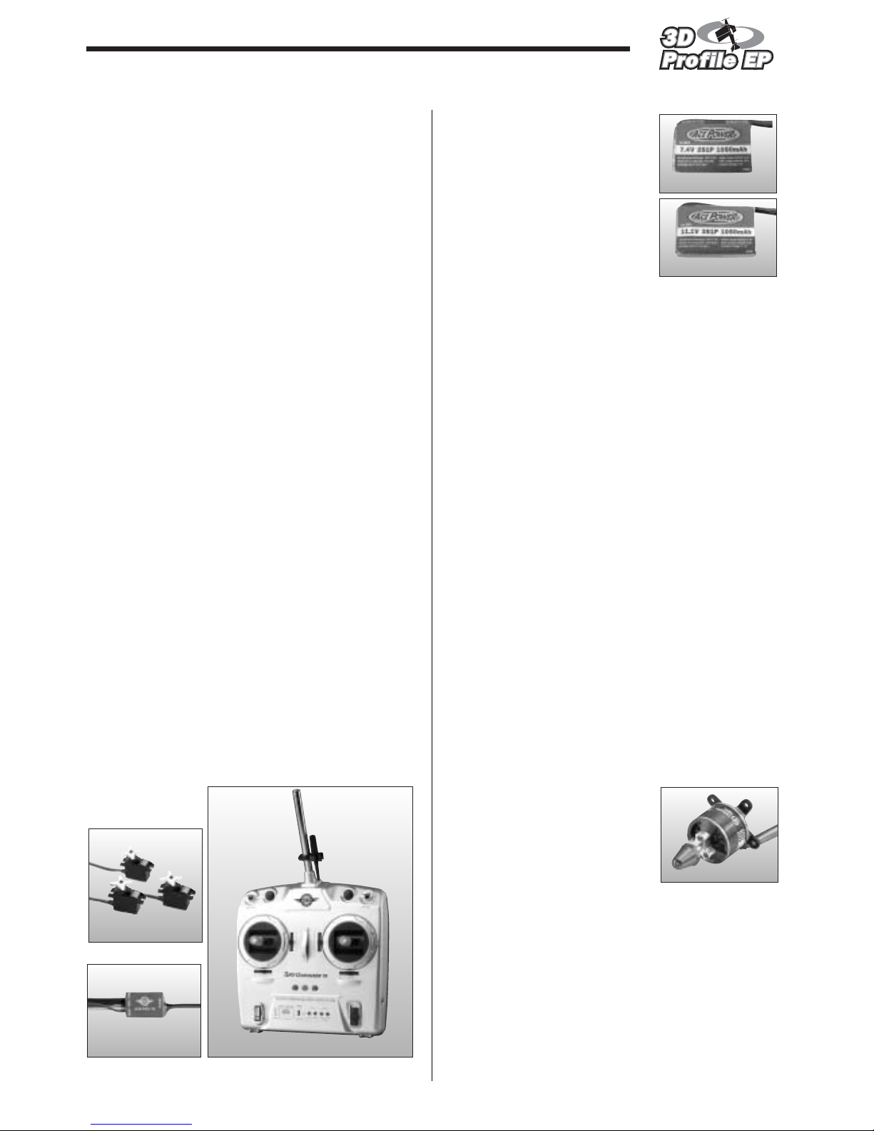
Radio: You will need at least a 4 channel radio
control system with 3 sub-micro servos and mini
receiver on an aircraft frequency for use in your 3D
profiles EP.
ESC: We recommend a quality Speed Controller for
this plane like Ace ESC-10 is recommended.
Lipoly Battery: Suggest to use
Quality 2~3-cell Lipoly battery
instead of any other NiCd or
NiMH battery pack. The
advantage of Lipoly battery is
much lighter than the traditional
Nicd or NiMH battery pack of the
same capacity. Thunder Tiger
provide high performance Ace
Power Lipoly Battery which is at
true discharge rate at 13C that
most 3D pilots are looking for. The 2-cell Li-Poly
battery is for normal flight yet 3-cell is good for 3D
aerobatics.
Lipoly Charger: You will need a performance Lipoly
battery charger to charge your Lipoly battery either at
flying field or home. Always pay high attention when
you’re charging the Lipoly battery. Get a charger with
alarm system and computerized charger with LCD
screen that shows charging status. This will help you
monitor the battery easily and safely.
Extension Wire: You will need a short extension
wire for aileron servo.
MOTOR CARE
The included Super 370 motor is designed for 2~3cells use yet we recommend you break-in the motor
properly to extend the life of the motor. The following
are some tricks :
1. Drop some oil on both bushing at the end caps of motor.
2. Break-in the motor for couple minutes at about 4.8 V
without loading.
3. Apply oil after every 5 flights for best performance.
4. Do not fly continuously without letting motor have
chance to cool down. This will hurt motor badly. Make
sure motor is cool before you perform next flight.
5. Motor Heat Sink will help cooling and you can get this
heat sink at any hobby shop.
OBL:
Thunder Tiger OBL outrunner
brushless motor 29 series is
available for upgraded power. For
more information please browse
website at www.thundertiger.com
TOOLS AND SUPPLIES NEEDED
Mixing Stick for Epo xy
Rubbing Alcohol
Paper Towels
Hobby Knife
Ruler
Pen, Pencil or Maker
Small Screw Drivers
No.8117AC
No.8015AC
No.8416 ACE Commander 4FD
No.2800 2cell 1050mAh
No.2801 3cell 1050mAh
Page 4
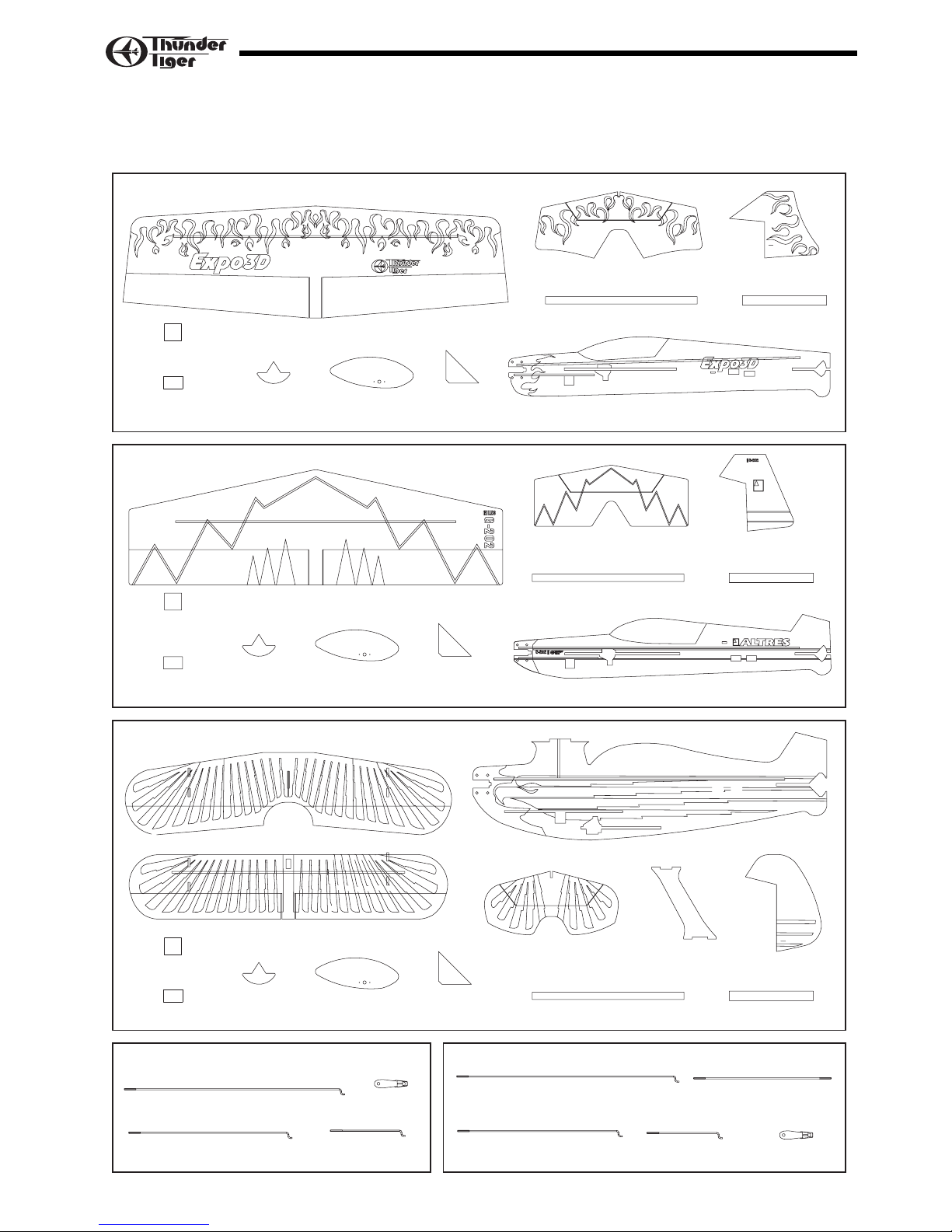
2
Horizontal T ail (1)
Main Wing (1)
Fuselage (1)
Triangle Balsa Wood (2)
Velcro (1)
Double Side Tape (1)
Tail Skid (1) Wheel Pant (2)
Tape (1)
Square (2)
Rudder (1)
Elevator Pushrod (1)
Aileron Pushrod (2)
Elevator Pushrod (1)
Aileron Pushrod (2)
Clevis (4)Rudder Pushrod (1)
Aileron Linkage Rod (2)
Clevis (4)
Rudder Pushrod (1)
AS6350 Foamy Set Expo 3D
AS6351 Foamy Set G202 3D
AS6352 Foamy Set Christen Eagle 3D
AS6359 Linkage Set (Expo 3D, G202) AS6363 Linkage Set (Christen Eagle)
Velcro (1)
Double Side Tape (1)
Horizontal T ail (1)
Main Wing (1)
Lower Wing (1)
Upper Wing (1)
Fuselage (1)
Fuselage (1)
Triangle Balsa Wood (2)
Tail Skid (1) Wheel Pant (2)
Tape (1)
Square (2)
Rudder (1)
Horizontal T ail (1)
Wing Support (2) Rudder (1)
Triangle Balsa Wood (2) Tape (1)
Velcro (1)
Double Side Tape (1)
Tail Skid (1) Wheel Pant (2)
Square (2)
Open the box and check that you have all the parts as shown below. If anything is missing please contact
your dealer. Parts shown in this page are vary in foamy and linkeg sets of each kit.
PART DRAWINGS
Page 5
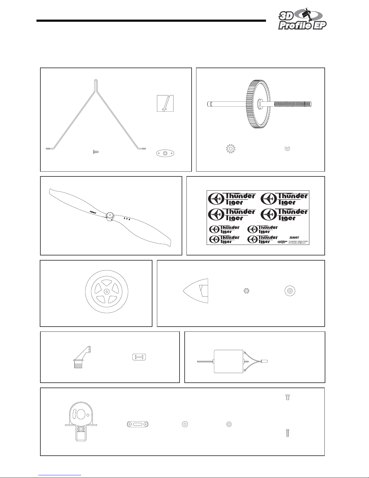
3
PART DRAWINGS
Wheel (2)
E Clip (1)
M3 Nut (2) Prop Washer (1)
Rubber Spinner (1)
Motor (1)
Motor Mount (1)
3 x 5mm
Machine Screw (2)
2 x 8 mm
Self-Tapping Screw (4)
Mounting Strip (2) Washer (2)
Spur Gear/Drive Shaft (1)
Pinion (1)
AS6355 Drive Shaft
AS6361 Decal
AS6358 Control Horn AS6357 Super 370 Motor
AS6356 Motor Mount
AS6336 Wheel AS6354 Spinner
Landing Gear (1)
2x5 mm
Washer Screw (2)
Mount (1)
Retainer (2)
Propeller (1)
AS6360 Landing Gear
No. 3549 11x 8 SF Propeller
Decal (1)
Bearing (2)
Control Horn (4)
Back plate (4)
Parts shown in this page are same for all 3D Profile EP planes.
Page 6
4
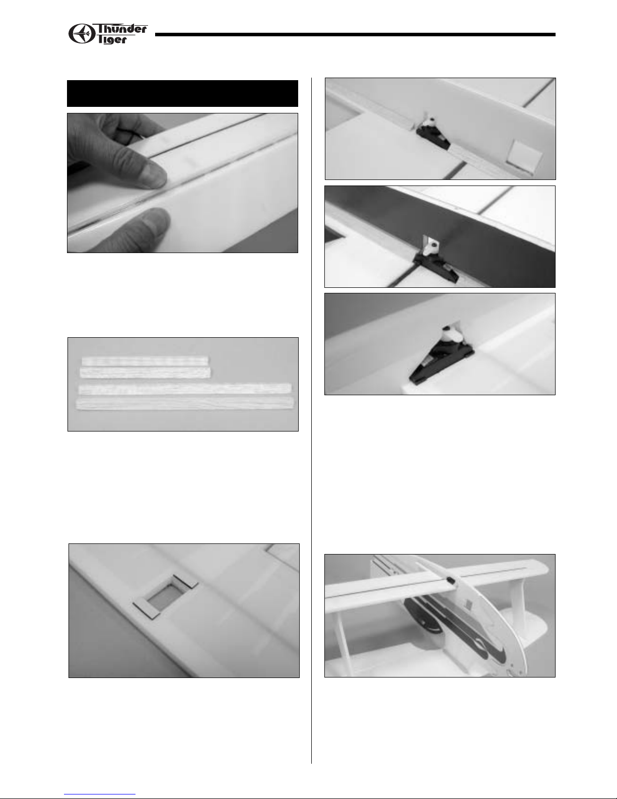
ASSEMBLY / WING
4. Note the orientation of servo output shaft and
install aileron servo on the wing first. Do not glue
the wing before you install the aileron servo. Next
connect the servo wire to RX and turn on radio to
make sure the servo rotating direction is correct.
Secure the servo horn with the screw which
comes with the servo. Now you can center and
epoxy the main wing in place. Reinforce wing with
triangle Balsa wood. Note the servo wire should
go right side as RX and ESC will be installed at
right side of fuselage later.
5. For Christen Eagle owner
Locate wing support and epoxy the wing support and
upper wing in place as shown.
It will be easier if you place the airplane up side down
to apply epoxy at the joints.
1. Check all pre-hinged aileron and elevator, lightly
press the taped area and make sure the aileron
and elevator will not come apart. You will also
have to check this before and after each flight to
get precise throws for better performance.
2. Cut triangle balsa wood as indicated length which
is going to reinforce the main wing later and keep
the rest wood for elevator.
Expo 3D: 13.5cm; 6.5cm (5-1/4”, 2-1/2”)
G202: 13cm; 8cm (5-1/8”, 3-1/8”)
Christen Eagle: Lower Wing–1cm;9.5cm (3/8”, 3-3/4”)
Upper Wing– 11cm (4-1/4”)
3. Get the furnished servo tape 3/16"x 1/2"
(5x12mm) and place as shown.
ASSEMBLY
Expo 3D
G202
Christen Eagle
Page 7
5
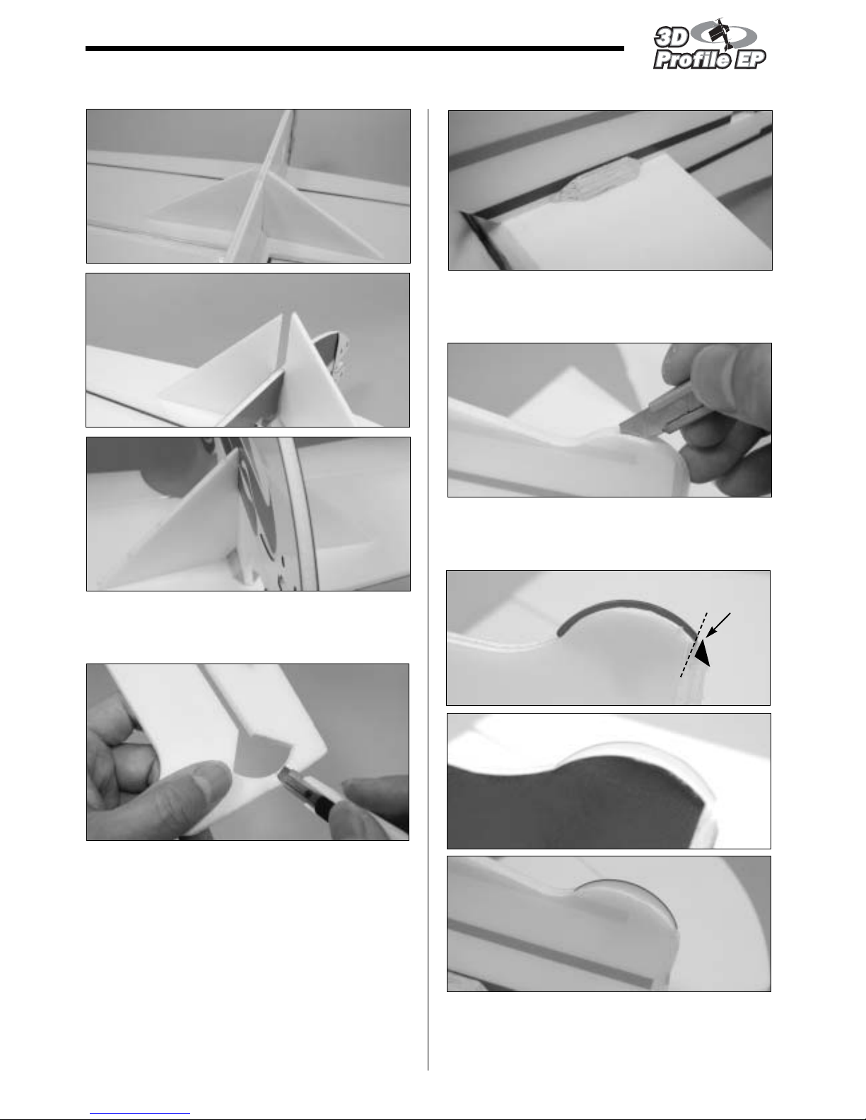
6. Use furnished square and make sure wing is
perpendicular to the fuselage while gluing wing
and fuselage together.
7. For Expo 3D and G202, it is necessary to cut
fuselage tail so the horizontal fin could go in.
8. Epoxy the tail in place. You may use the rest
triangle balsa wood and epoxy it at the bottom of
horizontal tail.
9. Locate the tail skid, next use hobby knife to cut a
slot at the bottom of fuselage tail. Then insert the
tail skid in place.
10.Glue the tail skid in place as shown. For Expo 3D,
you may need to cut one end of skid so it will not
have any influence to rudder movement.
ASSEMBLY / TAIL
Expo 3D
G202
Christen Eagle
Expo 3D
G202
Christen Eagle
CUT
Page 8
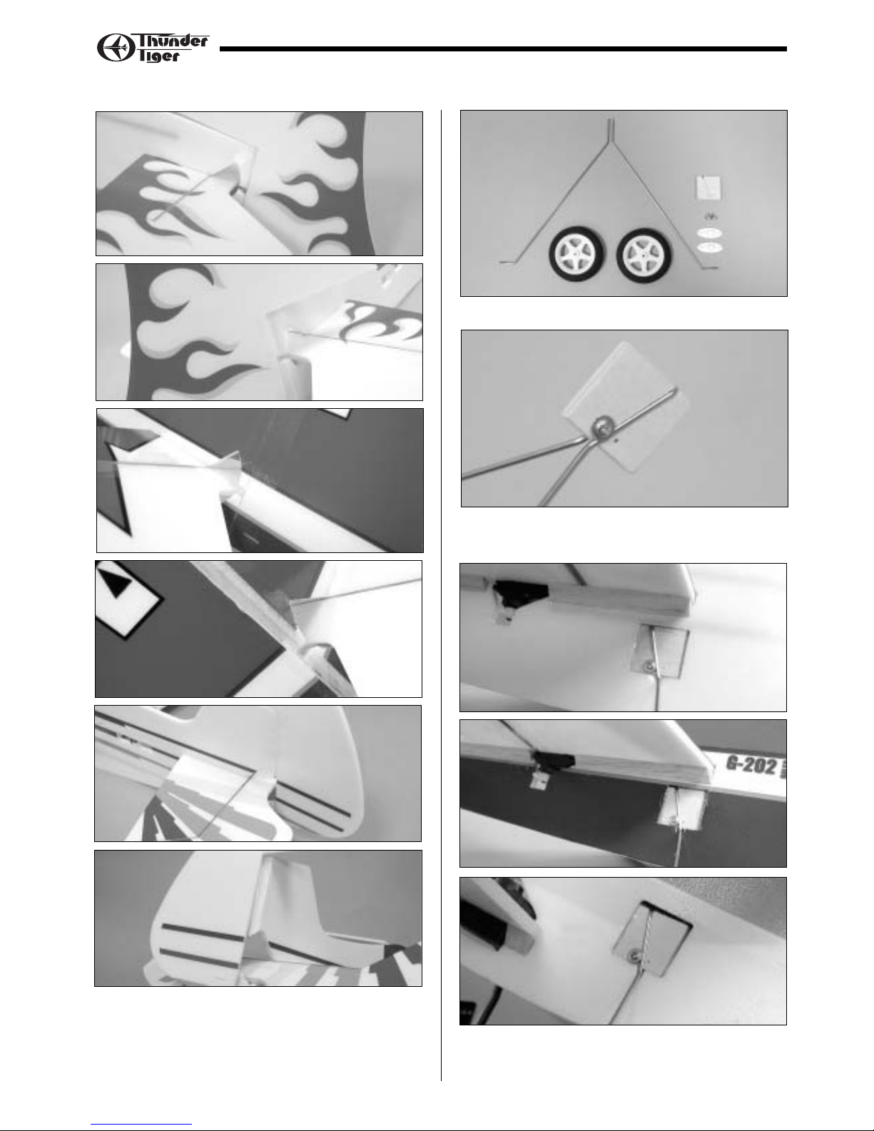
12.Locate landing gear parts and wheels as shown.
13.Secure the landing gear on plywood with furnished
2 x 5mm washer wood screws.
14.Epoxy the landing gear assembly in the hollow
square area.
6
ASSEMBLY / LANDING GEAR
11.Use the furnished tape to tape the Rudder in
place. Tape the left side first then the right side.
Expo 3D
G202
Christen Eagle
Expo 3D
G202
Christen Eagle
Page 9

7
19.Install aileron control horns.
20.Install aileron pushrods as shown.
21. For Christen Eagle owner, please install control
horn on two wings for aileron linkage.
22. Locate aileron lingage rod and thread clevises on
two ends. Snap the clevis on the lowest hole of the
control horn for best control throw.
15.Install wheels by threading the wheel pant retainer
in proper position.
16.Epoxy the wheel pants on the retainer. Make sure
two wheel pants are parallel.
17.Install rudder control horn, slowly inser t the
control horn to avoid any damage of surface at
the other side.
18.Press and lock the control
horn by the backplate.
Note the orientation of the
backplate. Apply tiny of
epoxy will help secure the contorl horn in place
firmly.
ASSEMBLY / SERVO
Epoxy
Page 10

8
ASSEMBLY / SERVO
25.Install the elevator and rudder pushrods when
servos are in neutral position and make sure
rudder and elevator are even with the vertical fin
and horizontal tail respectively.
23.Use the same way to install control horns for
elevator and rudder.
24.Install rudder and elevator servo note the
orientation of servo output shaft. Above photos
shown are all at left side.
Expo 3D
G202
Christen Eagle
Expo 3D
G202
Christen Eagle
Page 11

9
29.Secure power unit on the fuselage with the
mounting plates by four 2x8mm self-tapping
screws. Drive shaft should be in line with the
fuselage without qny thrust angle.
30.Locate M3 nut, put it in the propeller then thread
the propeller on the drive shaft. Next attach
propeller washer and another nut. Secure it firmly
and make sure to leave at least 6mm drive shaft
for rubber spinner.
31.Install the rubber spinner on drive shaft properly
and make sure it is not transformed.
26.Locate all the parts of universal power unit.
27.Press the bearings all the way in then insert the
Spur Gear Drive Shaft. Snap on the E clip. Tr y
pull the drive shaft and make sure E clip is well
positioned and drive shaft will not come off.
28.Install the motor in the power unit. To get good
gear mesh, use a piece of thin paper and set
between the pinion and spur gear. Then secure
the motor tightly with 3x5mm machine screw and
washer. Remove the paper by rotating the gear.
ASSEMBLY / MOTOR
Page 12

10
ASSEMBLY / RX, ESC, BATTERY
32.Connect the servo wires to receivers and speed
controller as shown. You will need one ser vo
extension to connect aileron servo. Use Velcro to
secure battery as photo shown. Secure the RX
and ESC with the furnished Double-Sided tape.
Organize the wires and fix them on fuselage with
tape if necessary.
33.Route the antenna wire to the tail and tape it on
fuselage.
CONTROL THROWS
The following contorl throw of 3D Profile EP is merely
a starting point for your radio setup and can be
tailored to fit your flying syle.
For All three models the aileron and elevator are of the
same throws but rudder are different as shown below.
Expo 3D & G202
Christen Eagle
Elevator-Low Rate
Aileron-Low Rate
Aileron-High Rate
Elevator-High Rate
Rudder-Low Rate
Rudder-High Rate
Expo 3D
Rudder-Low Rate
Rudder-High Rate
G202
Rudder-Low Rate
Rudder-High Rate
Chrstin Eagle
1"
1"
3/4"
3/4"
1-1/4"
1-1/4"
2-1/2"
2-1/2"
1-1/2"
1-1/2"
1-3/4"
1-3/4"
2-1/4"
2-1/4"
1-1/2"
1-1/2"
1-3/4"
1-3/4"
1-1/4"
1-1/4"
Page 13

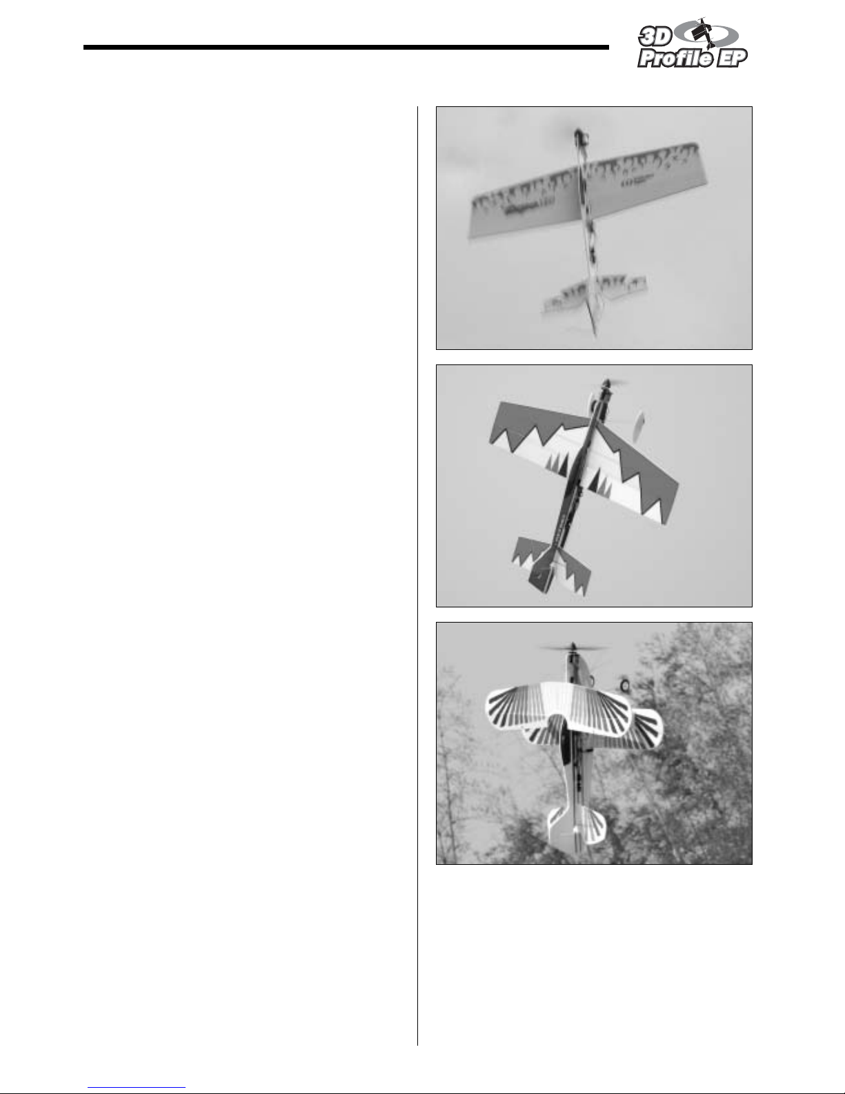
BALANCE
It is important to balance the plane to get correct CG
before you fly.
Balance Point as indicated in each diagram.
Expo 3D
G202
Christen Eagle
Note: For the best flight performance of the Christen
Eagle, a high center of gravity is important. Following
the manual shown in Step 32 which shows the
location of battery.
11
3-1/4"~3-1/2" ( 8.5~9cm)
C.G.
3-3/4"~4" ( 9.5~10cm)
C.G.
3-1/2"~4" (9~10cm)
C.G.
LONGITUDE BALANCE
As 3D planes do a lot of hovering so it is very
important to do longitude balance to make hovering
much more stable. Try to create a small hole after the
motor and on the thrust line. Get music wire or string
then thread the wire through the hole. Make sure that
model hangs perfectly vertical as illustration. If not
then try to adjust the location of battery, receiver or
ESC to get good longitude balance.
CONGRATULATIONS
Your done, may you have many successful flights filled
with fun and lots of 3D maneuvers.
Thank you for purchasing this 3D Profile EP from
Thunder Tiger and we look forward to providing you
with other great R/C products in the near future.
ASSEMBLY / BALANCE
C.G. Must be Set on Thrust Line
C.G. is Too Low
C.G. is Correct
Page 14

12
SETTING UP FOR 3D FLIGHT
Exponetial
To make your 3D flight successful, the most important
is to set up your radio properly and fine-tune the
exponential. We would suggest you use a
computerized radio plus a big LCD screen that could
show the exponential graph as the illustration.
Normally this computerized radio has dual rates or
even triple rates. Once you fly it fine with low rate in
normal flight, next you will have to set up 3D rate.
We suggest the 3D-rate setting is same as low-rate
setting around 1/3 of the total stick travel in the
beginning. If you look at the graph, the middle section
of 1/3 travel are most likely the same at low rate and
3D high rate. Beyond this middle section the 3D rate
setting is far higher than the low rate.
SimulatorA good tool to practice 3D easier is to
fly simulator. One may say simulator is not realistic
but this is not true. There are some simulators
available in the market and its scenery and
performance are just like a real thing. For example,
Aerofly Pro Deluxe USB version from Ikarus or Real
Flight G3 from Greatplanes are all good simulators
you can choose from.
Simulator is a must buy tool if you seriously want to fly
3D aerobatics. There is no genius or born 3D pilot,
remember that practice makes perfect. 30 minutes a
day on a simulator can help you do hovering, torque
roll easily as well as other aerobatics. If you would like
to be a good 3D pilot, flying everyday is necessary.
The reaction to control the airplane will be more
nature. As there is no time to think when you do 3D
aerobatics.
Simulator practice might be perfect yet we suggest to
do some actual flying as the supplemental so it will not
go too far from the real thing as there are many things
that you can not learn in the screen.
Servo Output
High Rate
Stick Travel
1/3 1/31/3
Low Rate
ASSEMBLY / 3D SETUP
Page 15
CG
Normally the correct CG position is beneficial to
hovering flight. Actually, for 3D profiles its CG range is
pretty large. Just give enough control surface
movement, softened correctly with exponential throws
then you may control the plane at a large range of CG
positions. Why, it is because no airfoil of the plane.
The only force to keep it in air is the thrust.
Flying
Even though you set up the airplane, it needs to be
setup and fine-tuned in the air. Always start on low
rates when launch the airplane or take off of the
ground. Once you fine trim the airplane in the air then
tune the exponential setting, you will be able to fly it all
the time on the 3D rates.
Once you got confidence to do hovering or do 3D
aerobatics, we suggest you fly it near you. The closer
the airplane, the better you can control the plane as
you can see it very clear even if it has a slight
movement. The other advantage is the lower or closer
to ground, the less damage of the plane as it has less
potential energy. It is useful for a dead battery or ESC
cut off suddenly.
13
ASSEMBLY / 3D SETUP
Page 16

THUNDER TIGER CORPORATION http://www.thundertiger.com
JE6695
GENERAL
1) I will not fly my model aircraft in sanctioned events,
air shows or model flying demonstrations until it has
been proven to be airworthy by having been
previously, successfully flight tested.
2) I will not fly my model higher than approximately
400 feet within 3 miles of an airport without notifying
the airport operator. I will give right-of-way and
avoid flying in the proximity of full-scale aircraft.
Where necessary, an observer shall be utilized to
supervise flying to avoid having models fly in the
proximity of full-scale aircraft.
3) Where established, I will abide by the safety rules
for the flying site I use, and I will not willfully and
deliberately fly my models in a careless, reckless
and/or dangerous manner.
4) The maximum takeoff weight of a model is 55
pounds, except models flown under Experimental
Aircraft rules.
5) I will not fly my model unless it is identified with my
name and address or AMA number, on or in the
model. (This does not apply to models while being
flown indoors.)
6) I will not operate models with metal-bladed
propellers or with gaseous boosts, in which gases
other than air enter their internal combustion
engine(s); nor will I operate models with extremely
hazardous fuels such as those containing
tetranitromethane or hydrazine.
RADIO CONTROL
1) I will have completed a successful radio equipment
ground range check before the first flight of a new or
repaired model.
2) I will not fly my model aircraft in the presence of
spectators until I become a qualified flier, unless
assisted by an experienced helper.
3) At all flying sites a straight or curved line(s) must be
established in front of which all flying takes place
with the other side for spectators. Only personnel
involved with flying the aircraft are allowed at or in
the front of the flight line. Intentional flying behind
the flight line is prohibited.
4) I will operate my model using only radio control
frequencies currently allowed by the Federal
Communications Commission. (Only properly
licensed Amateurs are authorized to operate
equipment on Amateur Band frequencies.)
5) Flying sites separated by three miles or more are
considered safe from site-to site interference, even
when both sites use the same frequencies. Any
circumstances under three miles separation require
a frequency management arrangement, which may
be either an allocation of specific frequencies for
each site or testing to determine that freedom from
interference exists. Allocation plans or interference
test reports shall be signed by the parties involved
and provided to AMA Headquarters. Documents of
agreement and reports may exist between
(1) two or more AMA Chartered Clubs,
(2) AMA clubs and individual AMA members not
associated with AMA Clubs, or
(3) two or more individual AMA members.
6) For Combat, distance between combat engagement
line and spectator line will be 500 feet per cubic
inch of engine displacement. (Example: .40 engine
= 200 feet.); electric motors will be based on
equivalent combustion engine size. Additional
safety requirements will be per the RC Combat
section of the current Competition Regulations.
7) At air shows or model flying demonstrations, a
single straight line must be established, one side of
which is for flying, with the other side for spectators.
8) With the exception of events flown under AMA
Competition rules, after launch, except for pilots or
helpers being used, no powered model may be
flown closer than 25 feet to any person.
9) Under no circumstances may a pilot or other person
touch a powered model in flight.
2004 Official AMA
National Model Aircraft Safety Code
 Loading...