

Page 1

Assembly Manual
1
Thunder Tiger 3D Spirit ARF Airplane (TTR4572)
Distributed in North America by Ace Hobby Distributors, Inc. • 2055 Main Street, Irvine, CA 92614
Telephone: 949.833.0088 •
wwwwww..aacceehhoobbbbyy..ccoomm
• E-mail: service@acehobby.com
Wing Span: 53"(1350mm)
Length: 57" ( 1438mm)
Wing Area: 725 sq.in.( 46.8 dm
2
)
Weight: 4.5~5 lbs.(2000~2200g)
Engine: .46~.50 2C
Radio: 4 channel 5 servos req'd
SSppeecciiffiiccaattiioonnss::
Warranty
This kit is guaranteed to be free from defects in material and workmanship at the date of purchase. It
does not cover any damage caused by use or modification. The warranty does not extend beyond the
product itself and is limited only to the original cost of the kit. By the act of building this user-assembled kit,
the user accepts all resulting in liability for damage caused by the final product. If the buyer is not prepared
to accept this liability, it can be returned new and unused to the place of purchase for a refund.
Notice: Adult Supervision Required
This is not a toy. Assembly and flying of this product requires adult supervision.
Read through this book completely and become familiar with the assembly and flight of this airplane.
Inspect all parts for completeness and damage. If you encounter any problems, call us for help.
JE6643
Page 2

2
IINNTTRROODDUUCCTTIIOONN
PPRREE--AASSSSEEMMBBLLYY NNOOTTEESS
Congratulations on the purchase of one of our finest ARFs to date. This plane is designed for 3D
aerobatics and available in ARF version that only takes you a few hours in assembly. Built from
precisely laser cut balsa and ply, covered in durable and easily repairable Oracover/Ultracote
®
, ultra
flying characteristic that you will enjoy.
3D Spirit Balsa
Oracover
Before the start of the assembly read the instructions thoroughly to have an understanding of
the sequence of steps and a general awareness of the recommended assembly procedures.
By following these instructions carefully and referring to the corresponding pictures, the
assembly of your model will be both enjoyable and rewarding. The result will be a well built, easy
to assemble A.R.F. model, which you will be proud to display.
TThhiiss 33DD SSppiirriitt iiss ddeessiiggnneedd ffoorr iinntteerrmmeeddiiaattee ttoo aaddvvaanncceedd ppiilloottss,, aanndd tthhiiss mmaannuuaall aassssuummeess bbaassiicc
kknnoowwlleeddggee ooff RR//CC mmooddeell ccoonnssttrruuccttiioonn..
Before you begin, check the entire contents of your kit against the parts list and photos to make
sure that no parts are missing or damaged. This will also help you to become familiar with each
component of your plane. If you find that any of the parts are either missing or damaged, please
contact Ace Hobby Distributors, Inc., Customer Service immediately for replacements.
Please read the entire manual before beginning construction, specially the cautions in
Page 18. Neither your dealer nor Ace Hobby Distributors, Inc., can accept kits for return
if construction has begun.
Trial fit each part before gluing it in place. Make sure you are using the correct part and that it
fits well before assembling. No amount of glue can make up for a poor-fitting part.
TTAABBLLEE OOFF CCOONNTTEENNTTSS
IInnttrroodduuccttiioonn................................................................................................................................ 22
RReeccoommmmeennddeedd TToooollss && MMaatteerriiaallss.................................................. 33
PPaarrttss DDrraawwiinnggss...................................................................................................................... 44--55
PPaarrttss CChheecckk LLiisstt................................................................................................................ 66
WWiinngg AAsssseemmbbllyy.................................................................................................................... 77--99
TTaaiill AAsssseemmbbllyy.......................................................................................................................... 1100--1122
EEnnggiinnee IInnssttaallllaattiioonn............................................................................................................ 1133--1144
CCoowwll AAttttaacchhmmeenntt............................................................................................................ 1155
CCaannooppyy IInnssttaallllaattiioonn........................................................................................................ 1166
BBaallaannccee.................................................................................................................................................... 1177
PPrree--FFlliigghhtt CCaauuttiioonnss...................................................................................................... 1188
OOtthheerr PPllaanneess............................................................................................................................ 1199--2200
Page 3
3
RREECCOOMMMMEENNDDEEDD TTOOOOLLSS && MMAATTEERRIIAALLSS
Adhesives:
Instant setting Cyanoacrylate adhesive
(thin CA)
Slow setting Cyanoacrylate adhesive
(thick CA)
5 Minute Epoxy (fast)
20-30 Minute Epoxy (slow)
Tools:
Model knife, T-Pins, 1/2" MASK tape
Small screwdrivers, medium screwdrivers
Scissors
Steel straight edge
Long nose pliers and diagonal cutting pliers
Drill and drill bits (1/16", 5/64", 1/8")
Fine felt tip pen and soft lead pencil
Straight building board
Reamer
File
R/C System:
4 Channel radio with 5 servos
One “Y” style or two 10" extension wire
Two 20" extension wires
Engine:
2 cycle: .46~.50
Propeller:
Suggest 11x4.5, 12x4.
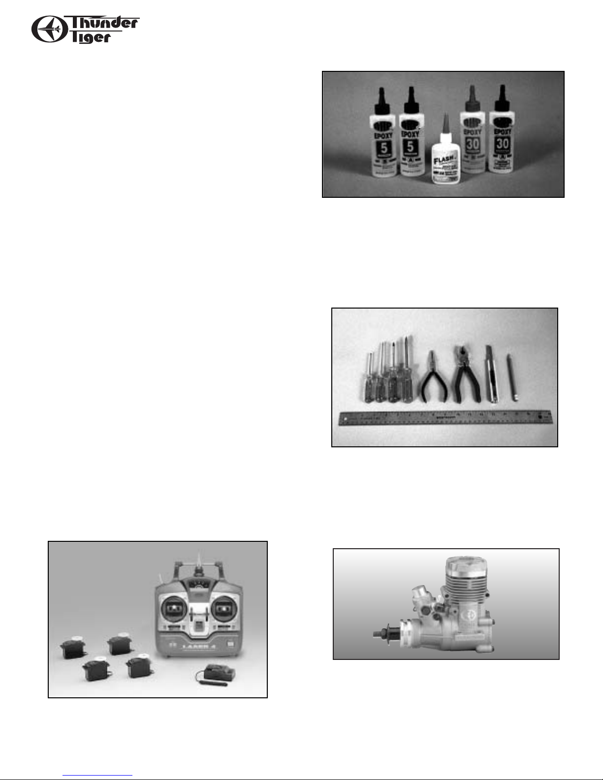
AAddhheessiivveess
- You will need two types of adhesives for
the 3D Spirit - Epoxy and Instant (cyanoacrylate)
adhesives. We recommend that you purchase both 5minute and 30-minute epoxy to cut down on assembly
time, but you can get by with only 30-minute epoxy if
time is not important. You will also need a small bottle
of both “Thick” and “Thin” instant CA adhesive.
TToooollss
- Model assembly can be much easier if the
proper tools are used. Therefore, we have included in
our checklist to the left, a complete listing of all the
tools we used to assemble our prototype models. As
you will notice, many household tools can be utilized
during construction.
EEnnggiinnee
- The Thunder Tiger PRO-46 is the ideal
engine for this airplane. These quiet-running engine is
easy to start, requires no special break-in periods, is
very easy to maintain and will last for years.
Radio - A 4-channel radio with 5 STD servos and are
required.
Page 4
4
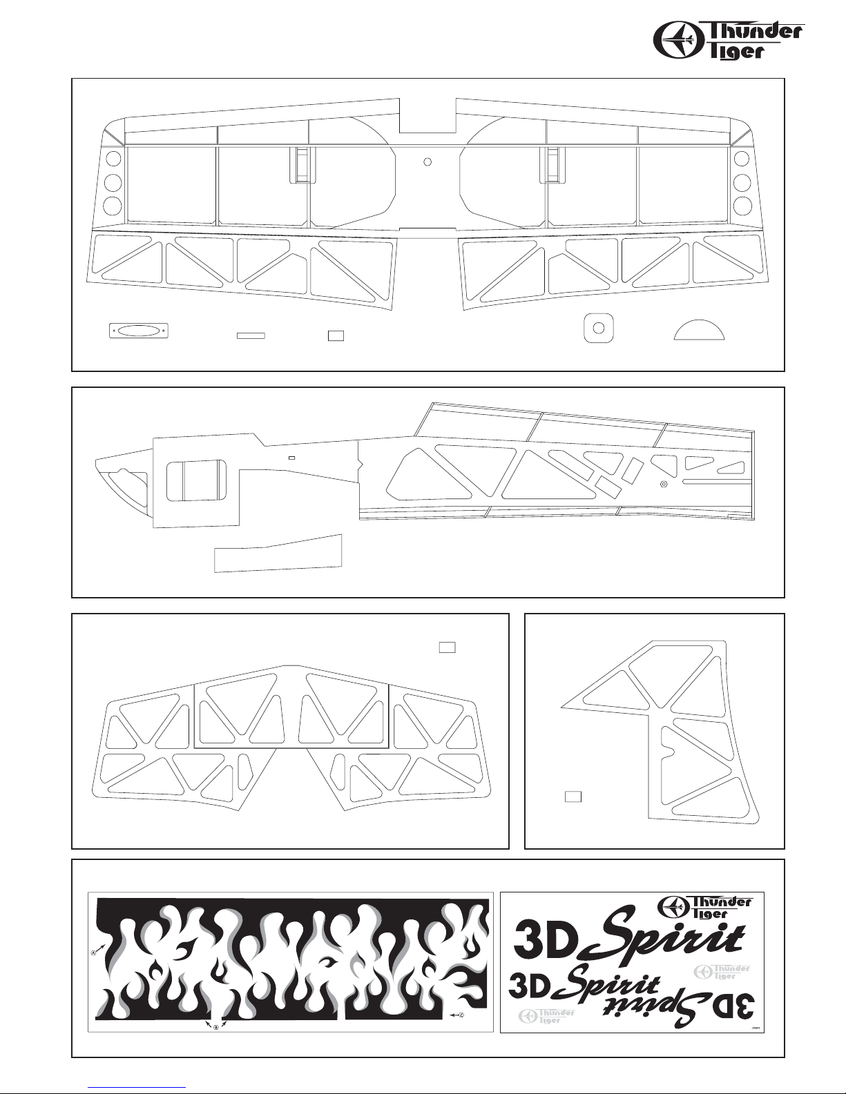
PPAARRTTSS DDRRAAWWIINNGGSS
AS6280 Main Wing
AS6281 Horizontal Tail
AS6279 Fuselage
AS6289 Decal
AS6282 Vertical Tail
Decal(2)
Main Wing(1)
CA Hinge(8)Dowel(2) Retainer(4)Wing Mounting Plate(1) Doubler(1)
Fuselage(1)
Bottom Section(1)
CA Hinge(4)
Horizontal Tail(1)
VerticalTail(1)
CA Hinge(3)
Decal(1)
Page 5
5
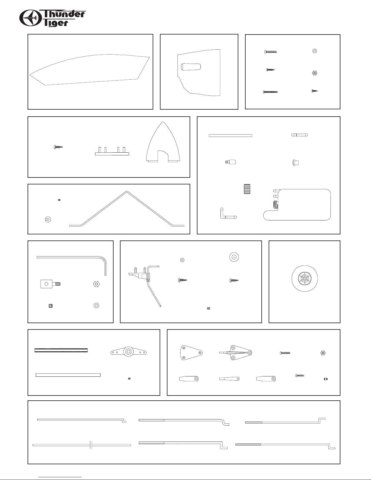
PPAARRTTSS DDRRAAWWIINNGGSS
AS6283 Canopy
Canopy(1)
No. 3278R Spinner
3x16mm
Self T apping Screw(4)
Back Plate(1)
AS6285 Main Landing Gear
3x3mm Set Screw(4)
AS6284 Engine Cowl
FRP Cowl(1)
Spinner(1)
AS6290 Screw Set
3x22mm Screw(4)
3x15mm
Wood Screw(4)
3x35mm
Wood Screw(2)
No. 3262 Fuel Tank
Silicone Tube(1) Straight Nipple (1)
Crank Weight (1)
Fuel Cap (1)
Fuel Stopper (1)
M3 Washer(6)
M3 Nut(4)
3x8mm
Wood Screw(10)
240cc (8oz.)
Collar(4)
PE0009 Hardware Set
Hex Wrench(1)
EZ Connector(1)
3x3mm Set Screw(1)
M2 Nut(1)
M2 Washer(2)
AS6287 Dual Linkage System
Tube(1)
Shaft(1)
3x3mm Set Screw(2)
Main Gear(1)
AS6178 Tail Gear
Tail Gear(1)
Control Arm(2)
90-degree Nipple (1)
Collar(1)
3x12 mm
Self-Tapping Screw(1)
3x3mm Set Screw(2)
Self-Tapping Screw(1)
AS6288 Control Horn
Back Plate(5) Control Horn(5)
Dia. 2.2 Clevis(1) Dia.2 Clevis(4)Metal Clevis(2)
Tail Wheel(1)
3x16mm
Tank (1)
No.3255 Wheel
Wheel(2)
2x14mm Screw(15) M2 Nut(7)
2x8mm
Screw(5)
Ball(5)
AS6286 Pushrod Set
Throttle Pushrod(1) Pushrod(2, S)
Guide Tube(1)
Aileron Pushrod(2, M)
Rudder Pushrod(1, 2.2mm)
Elevator Pushrod(2, L)
Page 6
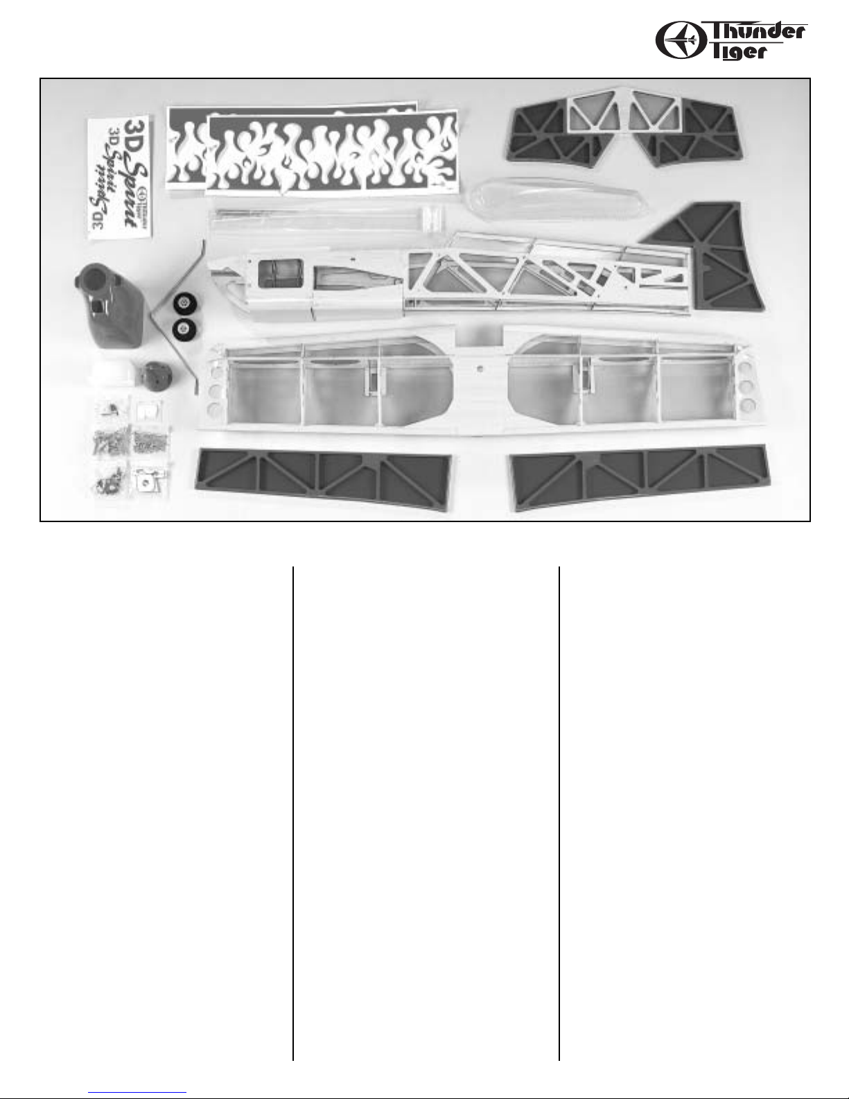
6
PPAARRTTSS CCHHEECCKK LLIISSTT
Tail Gear Set
Tail Gear x 1
Tail Wheel x 1
Collar x 1
3x3mm Set Screw x 2
3x12mm Wood Screw x 1
3x16mm Wood Screw x 1
Control Horn
Control Horn x 5
Backplate x 5
2 x14mm Screw x 15
M2 Nut x 7
Dia. 2.2mm Clevis x 1
Dia. 1.7mm Clevis x 4
Metal Clevis x 2
2x8mm Screw x 5
Ball x 5
EZ Connector
Connector x 1
M2 Nut x 1
M2 Washer x 2
3x3mm Set Screw x 1
Allen Wrench x 1
Fuel Tank
Tank x 1
Clunk x 1
Nipple x 1
90-degree Nipple x 1
Fuel Stopper x 1
Fuel Tube x 1
Cap x 1
Kit Contents:
Main Wing
One-Piece Main Wing x 1
Wing Mounting Plate x 1
Dowel x 2
CA Hinge x 8
Doubler x 1
Retainer x 4
Horizontal Tail
Horizontal Tail x 1
Elevator (Left/1, Right/1)
CA Hinge x 4
Vertical Tail
Rudder x 1
CA Hinge x 3
Fuselage
Fuselage x 1
Bottom Section x 1
Spinner
Spinner x 1
Backplate x 1
3x16mm Self-Tapping Screw x 4
Pushrod
Throttle Pushrod x 1
Guide Tube(1)
Aileron Pushrod(M) x 2
Rudder Pusherod(2.2mm) x 2
Pushrod (S) x 2
Elevator Pushrod(L) x 2
Main Landing Gear
Landing Gear Strut x 1
3x3mm Set Screw x 4
Collar x 4
Dual Linkage System
Tube x 1
Shaft x 1
Control Arm x 2
3x3mm Set Screw x 2
Decal
Fire Decal x 2
Logo Decal x 1
Screw Set
3x22mm Screw x 4
M3 Nut x 4
M3 Wahser x 6
3x15mm Wood Screw x 4
3x8mm Wood Screw x 10
3x35mm Wood Screw x 2
Wheel x 2
Engine Cowl x 1
Canopy x 1
Manual x 1
Page 7

7
WWIINNGG AASSSSEEMMBBLLYY
❐ 1. Decide the position of hinge then carefully cut
slots at trailing edge and aileron.
❐ 2. Insert hinges in place and use pin to position the
hinge in the center .
❐ 3. Attach the aileron to the trailing edge, remove
all pins then drop CA to the hinges at both sides.
Same procedure on the other aileron.
❐ 4. Locate the servo wire opening doubler, use fine
tip marker to mark where covering is going to
remove.
❐ 5. Remove the covering about 1/8"(3mm) inside
the line you drew. Be careful only cut the
covering or it will hurt the planking.
3mm
❐ 6. Glue the doubler in place with instant CA glue.
Page 8
8
WWIINNGG AASSSSEEMMBBLLYY
❐ 7. Remove the covering at the holes and epoxy
two dowels all the way in.
❐ 8. Remove the covering by a hobby knife at the
aileron servo well.
❐ 9. Thread the servo wire through wing panels and
exit at the servo wire exit hole. If you use a
standard 4ch radio then you will need a “Y”
style extension wire. Tape the connectors to
prevent from loosening. If you use a quality
programmable radio then we suggest you to use
two 10" long servo extension wires and turn on
the function of "Flapron" or Aileron-Flap
mixture control.
25cm
2 Flapron
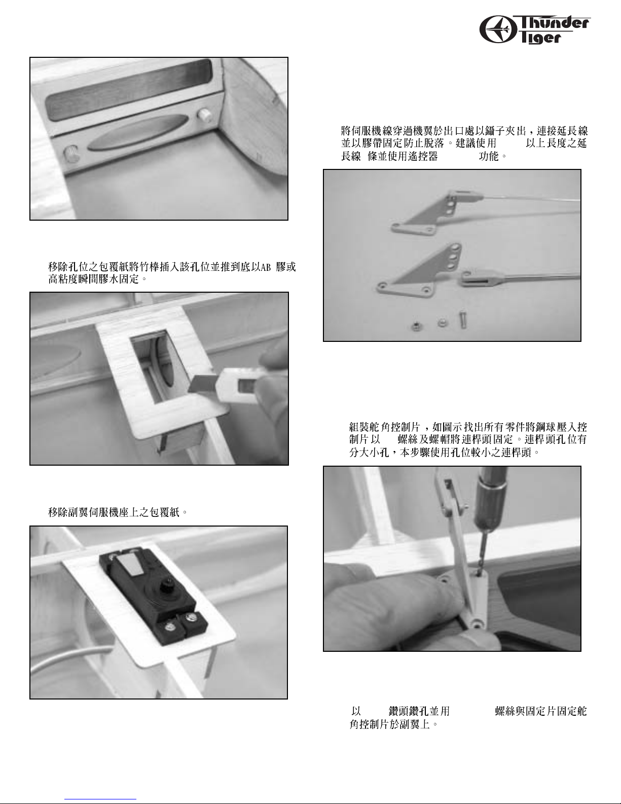
❐ 10.Locate the control horns. Install the control
horn as shown. There are 5 cleveises in the
parts bag and a special clevis which has larger
pushrod hole that is for rudder pushrod. Use
the clevis with small hole in this step.
M2
❐ 11. Place the control horn on the aileron with
aileron pushrod(M) installed. Drill 5/64"
(2mm) holes.
2mm 2x14mm
Page 9

❐ 12. Secure control horn with furnished 2x14mm
screws and control horn backplate.
?
?
?
?
?
?
?
?
)Xf?/X?hg?
@)f?V/Xhg?
@HgN1hg?
@?e?@K??@fO)X?g?
@?e?@@@@@@@@@@@,?g?
@W@KC(M?gW(Y?g?
@@@@@@@@@He)Xe?W.Yh?
@??I@??J@)e?.Y?h?
@?fO&Y?hg?
@W.?@@@@@@@@@@@@@?g?
@(Y?e@?f@?he?
?@@@@Hf@?f@?he?
?@M?@?e?J5?e?J5?he?
@?e?7U?e?7H?he?
@?eJ@)KeJ5hf?
@?e.MI46T&Uhf?
@?gS@@)K?he?
@?f?O.M?I46X?h?
@?e?W2(Y?e?I/Xh?
?@@@5?eO&0YgV/h?
I(Y?@@0M ?
?
?
?
?
?
?
?
?
?
Z
❐ 13. Trail fit main wing in place then place
fuselage bottom section and make marks on
the bottom wing.
❐ 14. Draw a parallel line offset about 5/32"(4mm).
Locate 4 pieces of bottom section mount and
place the mounts right on the lines as shown.
9
WWIINNGG AASSSSEEMMBBLLYY
Locate the wing mounting plate and place it
at the center and away from trailing edge
about 1/8"(3mm). Make marks around these
wood parts.
4mm
3mm
❐ 15. Remove the covering of the marks you made.
❐ 16. Glue the wood parts in place with thick CA or
epoxy. Note that wing mounting plate is
1/8”(3mm) away from trailing edge.
AB
Page 10
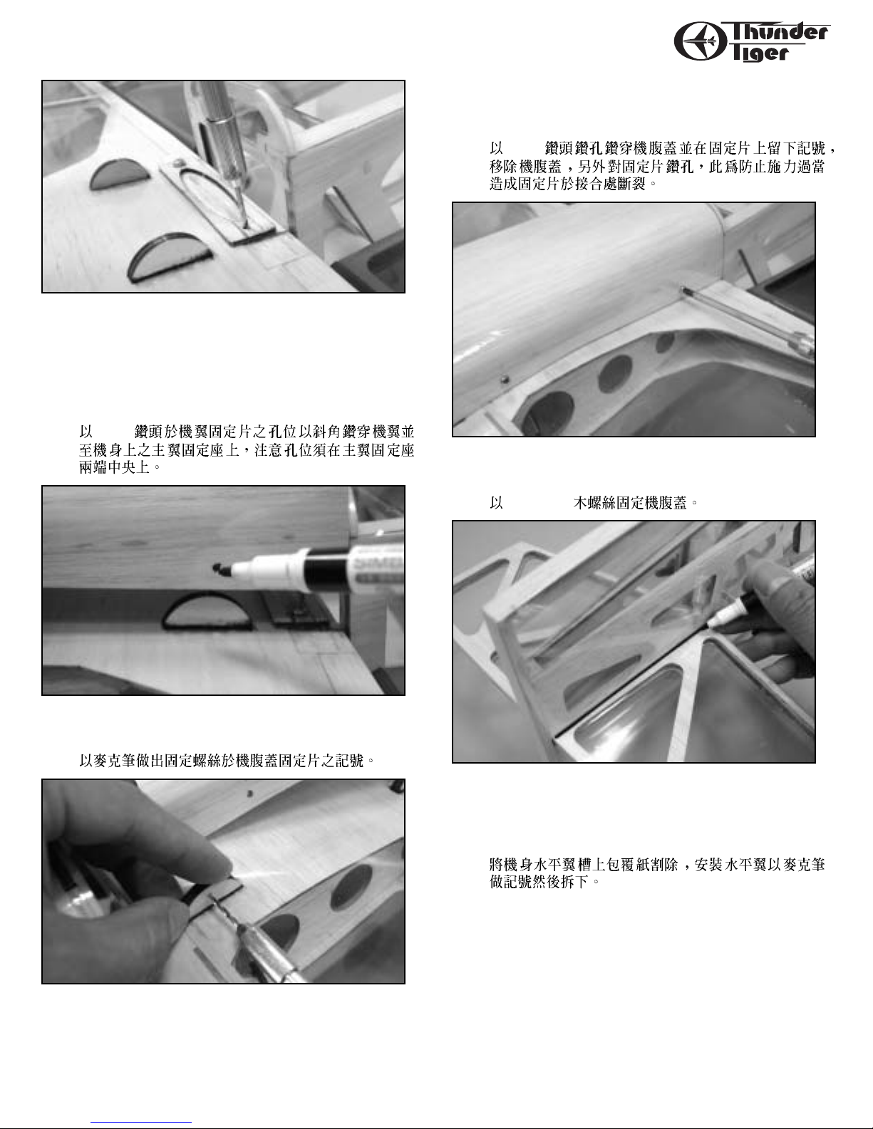
❐ 17. Fit the main wing on fuselage, drill
1/16"(1.5mm ) wing mounting holes. Be careful
to drill the hole through the wing and
mounting block on fuselage. The mounting
holes should be centered near two ends of
mounting block.
2mm
❐ 18. Trail Fit the bottom section. Make marks on
the bottom section.
❐ 19. Place the bottom section then drill
5/64"(2mm) holes. Drill the bottom section
and make a drill mark on bottom section
mount. Remove the bottom section then drill
10
TTAAIILL FFEEAATTHHEERRSS
the hole on bottom section mount as shown.
This is to prevent you from breaking the
mount when drilling.
2mm
❐ 20. Secure the bottom section with the furnished
3x 15 mm wood screw.
3x 15 mm
❐ 21.Remove the covering on the fuselage where
horizon tail goes. Insert the tail in place then
draw lines along fuselage on the tail at four
sides.
Page 11

11
TTAAIILL FFEEAATTHHEERRSS
❐ 22. Remove the covering about 1/16"(1.5mm)
inside the line you drew.
1.5mm
❐ 23. Cut hinge slots first on elevator and horizontal
tail. Glue the tail in fuselage then attach the
elevator.
❐ 24. Locate the parts of dual linkage system for
elevator. Insert and center the tube in fuselage,
glue it with thick CA. Next secure the control
arm on the shaft with 3x3mm set screw. Cut
away the elevator servo well covering.
3x3mm
❐ 25. Install elevator control horns and elevator
pushrods(L). Adjust two elevators so that they
are level with each other.
Z
❐ 26. Install tail gear on the fuselage. Secure the tail
gear with 3x12mm and 3x 16mm wood screws.
Secure the collar with 3x3mm set screw.
Apply a drop of oil at the tail gear shaft.
3x12mm 3x16mm
Page 12
12
TTAAIILL FFEEAATTHHEERRSS
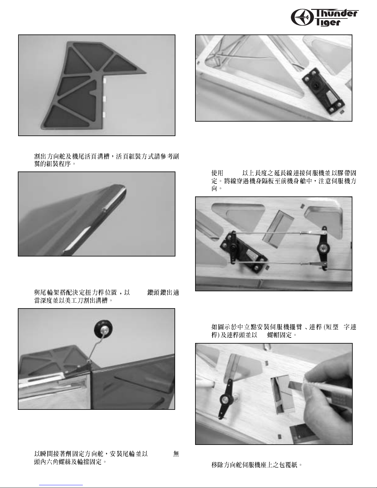
❐ 27. Cut slots on rudder and tail of fuselage.
❐ 28. Refer the photo in next step and drill a
5/64"(2mm) hole and carefully cut a slot for
tail gear torque rod.
2mm
❐ 29. Trail fit rudder, glue the tail gear and rudder
in place with thick CA when satisfied. Install
the tail wheel and secure the collar with
3x3mm set screw.
3x3mm
❐ 30. Connect a 20"(50cm) extension wire, make
sure you secure the connectors with tape.
Thread the servo wire through the bulkhead
of fuselage then secure the elevator servo in
place. Note the orientation of the servo.
50cm
❐ 31. Locate 2 pushrods(S size), install the push-pull
rod, M2 nut and metal clevis. Adjust the clevis,
make sure it moves smoothly.
Z
M2
❐ 32. Remove the rudder servo well covering.
Page 13
13
EENNGGIINNEE IINNSSTTAALLLLAATTIIOONN
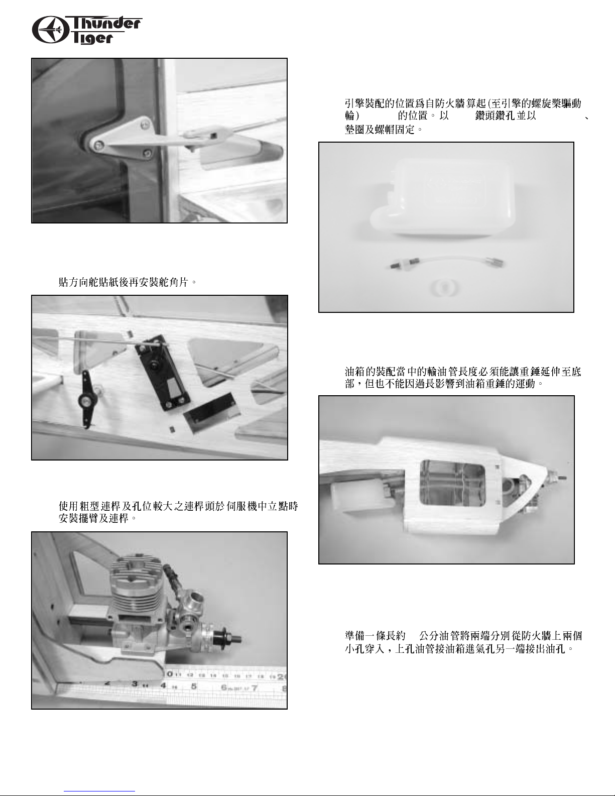
Drill 1/8" (3mm) engine mount holes then
secure the engine with furnished 3x22mm
machine screws, washer and nuts.
135mm 3mm 3x22mm
❐ 36. Assemble the fuel tank as illustrated. Make
sure the crank weight is free when tank is
assembled.
❐ 37. Prepare a fuel tubing about 16"(45cm) in
length( not included), thread two ends from
front firewall through the fuselage. Connect
to the fuel tank nipples.
45
❐ 33. Install rudder control horn. Before you install
the control horn, you may apply the decal (c)
first. See the color photos on box label.
❐ 34. Install the rudder pushrod (dia. 2.2mm). Use
the larger pushrod hole on clevis in this step.
❐ 35. Place the engine on the engine mount. It will be
5 3/8"(135mm) from the firewall to drive
washer. Make marks on engine mount holes.
Page 14

14
EENNGGIINNEE IINNSSTTAALLLLAATTIIOONN
❐ 38. Insert the fuel tank slowly and carefully in
place as shown. Pull the fuel tubing and note
the tank orientation. Make sure the tubing is
not bent.
❐ 39. Use a piece of paper to help you trim the cowl.
Decide the muffler position and make marks
on the paper. Cut away the marks you drew.
❐ 40. Install the muffler in place as shown, make
marks on paper which contacts the muffler.
❐ 41. Cut away the marks you drew and clear the
contact area as shown.
❐ 42. Remove muffler then attach the cowl in place.
Make sure the cowl is about 1/8"(3mm) after
the drive washer at spinner area. Then use the
paper as template to make marks on cowl.
2mm
❐ 43. Remove the cowl and trim away the marked
area. It might take time to trial fit and trim the
cowl to get good fitness. You can take away
the carburetor or needle valve for easy fitness.
Page 15

❐ 44.Drill holes for needle valve, muffler bolt,
mixture screw and Precision Fuel Value
(TTR1115) for easy fueling. A reamer is
recommended ( TTR1120) to drill holes.
No. 1120
No. 1115
❐ 45.Insert the pushrod guide tube through the
fuselage and glue it in place. Install the
throttle pushrod. You might need to remove
the throttle lever first then attach to Z-bend
throttle pushrod end.
3
❐ 46. Now connect all fuel lines properly, stick the
decals before securing the cowl. Install
spainner and propeller.
15
CCOOWWLL AATTTTAACCHHMMEENNTT
❐ 47. When satisfied, secure the cowl with four
3x8mm wood screw.
3x8mm
❐ 48.Locate the landing gear slot at bottom of
fuselage. Cut away the covering and remove
the landing gear retainer.
❐ 49. Install the landing gear in place and glue the
retainer with thick CA. Install the wheel and
secure by collar with 3x3mm set screw.
AB 3x3mm
Page 16

16
CCAANNOOPPYY IINNSSTTAALLLLAATTIIOONN
❐ 50.Trim the canopy along the molded line. Secure
the canopy in place with furnished six
3x8mm wood screws.
3x8mm
❐ 51.Install the throttle servo. Secure the EZ
connector with two M2 washers and nut on
the servo horn and adjust the throttle with
radio on then secure the throttle pushrod with
3x3mm set screw.
M2
❐ 52.Install the switch and connect to receiver.
Wrap the receiver and battery pack in foam
padding. Route the RX antenna and drill a
small hole on right side of fuselage. thread the
antenna out of fuselage then tape it along the
fuselage to tail.
Control Throws
These control throws are merely a starting point
for your radio setup and can be tailored to fit your
flying style.
Center of Gravity
IMPORTANT- Do not attempt to fly your model
before completing this very important section. A
model that is not properly balanced will be unstable
and could cause serious damage and/or injury.
Adjust the battery location or add weight as needed
to achieve level balance. Once you have everything
positioned as necessary, wrap your battery pack in
1/4" or 1/2" thick foam for protection.
The balance point is about 5.5” (14mm)
from the leading edge.
14
5.5" (14cm)
2" (5cm)
2" (5cm)
4" (10cm)
4" (10cm)
5/8" (1.5cm)
5/8" (1.5cm)
1 1/4" (3cm)
1 1/4" (3cm)
1" (2.5cm)
1" (2.5cm)
2" (5cm)
2" (5cm)
Ш௷௷ณ
ઘᓍ௷ณ
ࢫ௷௷ณ
Page 17

17
BBAALLAANNCCEE
Locate A Good Flying Site
Generally, the best place to fly your model is at
an AMA (Academy of Model Aeronautics) chartered
club field. Your local hobby dealer can tell you if
there is such a club in your area or write the AMA
for information. It is also a good idea to join this
organization before flying your model since they
offer liability insurance that can protect you if
your model causes damage or injury to others.
AAccaaddeemmyy ooff MMooddeell AAeerroonnaauuttiiccss
55115511 EEaasstt MMeemmoorriiaall DDRR
MMuunncciiee,, IINN 4477330022--99225522
If there is not a chartered club field in your
community, you will need to find a large area free
of obstructions, and has a smooth grass or asphalt
surface to be used as a runway. For safety’s sake, it
should be located well away from houses,
buildings, schools, power lines and airports. If you
will be flying within 6 miles of an airport, you
should check with the airport manager before
flying your model.
Congratulations
Now that you have completed the assembly of
your 3D Spirit, we feel that you have a very capable
and good looking sports plane. We hope that you
will enjoy this model and get many hours of flying
pleasure from its use. Thank you for purchasing
this 3D Spirit from Thunder Tiger and we look
forward to providing you with other great R/C
products in the future.
Refer to the indicated drawing and box label to stick the decals.
Page 18

18
Pre-Flight Cautions !
For satisfying 3D performance and safe sake please read the following
guidelines before you fly your 3D Spirit.
● Do not install engine over .50 cu.in. as it is overpowerful for this plane.
Normally a Thunder Tiger 46 could hover the 3D Spirit at its 70% output
power.
● Recommend using 11x4.5 or 12x4 propeller, smaller pitch is preferred.
● Always set low rate as manual instructed for the first flight or taking off
until you fine tune your plane.
● Since 3D plane is light weight structured and fantastic low/middle speed
maneuverability, never intend to fly your 3D Spirit at full throttle or high
speed
● Use care to check all control surfaces and linkage before each flight. Do
not take chances to fly the plane if there is any problem.
AAggaaiinn,, tthhiiss ppllaannee iiss nnoott ddeessiiggnneedd ffoorr oovveerrppoowweerr nnoorr ffllyyiinngg aatt hhiigghh
ssppeeeedd.. SSuucchh cchhooiicceess ppuutt yyoouurr mmooddeell aatt hhiigghh rriisskk ffoorr ccaattaassttrroopphhiicc
ffaaiilluurree aanndd vvooiidd aannyy pprrootteeccttiioonnss ooffffeerreedd iinn iittss wwaarrrraannttyy..
● 50 PRO-46 7
● 11x4.5 12x4
●
● 3D
●
●
33DD
Page 19
19
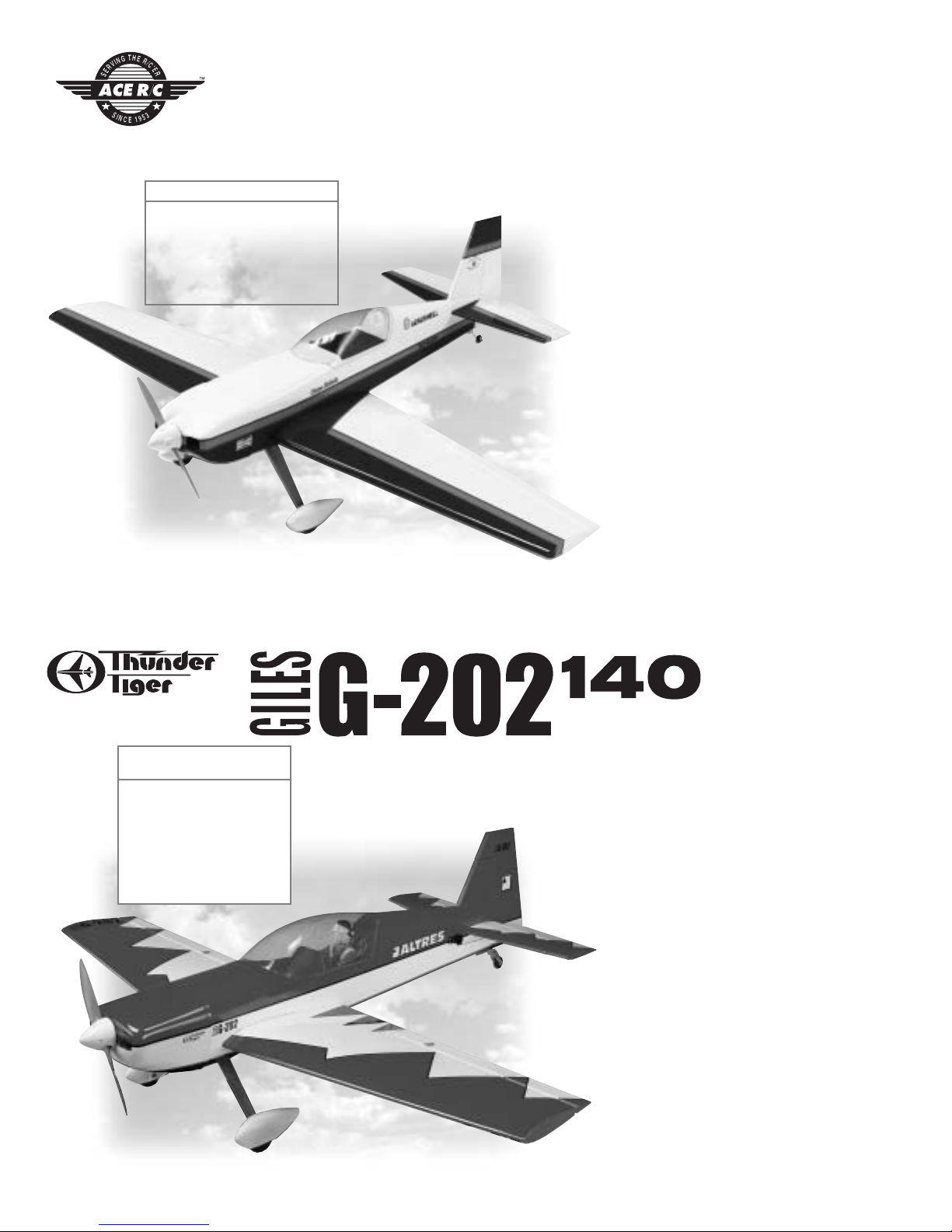
No.4550 G-202 140
Wing Span: 70”
Wing Area: 1022in
2
Length: 70”
Weight: 10-10.5 lbs.
Engine: 1.08-1.6 2cycle
1.2-1.8 4cycle
Radio: 4 channel
w/6 Servos
Staudacher 60 ARF
Combine the scale appearance and striking
color scheme of Diane Hakala's legendary
Staudacher S-300 with the late Fred Reese's
genius for light-weight yet sturdy
construction, and you have an Almost-ReadyTo-Fly airplane that will turn heads both on
the ground and in the air. Now you can enjoy
the experience of scale modeling without
investing the hundreds of hours of time
necessary to achieve satisfactory results.
Just because this is a scale airplane, don't
think it is a "lead-sled". It is an extremely
pleasurable airplane to fly with
characteristics akin to a comfortable sport
airplane rather than a fickle scale beauty.
Solid tracking, instant acceleration, nimble
aerobatics, and predictable landings make this
airplane fly as good as it looks.
Completely built from balsa/ply and
covered with UltraCote, this Almost-ReadyTo-Fly airplane is ready to load up for the field
in only a few short hours.
● Impressive scale appearance with sport
performance
● Completely built from balsa/ply and
covered with UltraCote
®
● Quality epoxy/fiberglass cowl is flawlessly
painted
ARF
Wild blue yonder takes on a whole new
meaning when you are pushing either of these
ARF Giles 202 through the sky. Crisp
aerobatics are what these replicas of the
world famous airplane is all about.
This Almost-Ready-To-Fly airplanes is
meticulously built from balsa/ply and
covered with UltraCote. A few hours of final
assembly plus radio and engine installation
and you are ready to head for the tarmac and
wave to the crowd after a successful airshow
performance.
● Skilled craftsmen completely build this
model from top quality balsa and plywood.
● Covered in Ultracote, the G-202 color
scheme is bright, tough, and repairable.
● A flawlessly painted fiberglass cowl, blow
molded wheel pants, and bottom wing
cover are furnished.
● Quality accessories include pilot figure and
instrument panel. The 1.40 includes scale
tail-wheel assembly, flexible engine mount,
and heavy duty linkage.
ACE4563 Staudacher 60
Wing Span: 65”
Wing Area: 780in
2
Length: 55.2”
Weight: 8.5-9.5 lbs.
Engine: .60 2 cycle
.90-1.20 4 cycle
Radio: 4 channel, 5 servos
ACE4563
No.4550
Page 20

20
THUNDER TIGER CORP . www.thundertiger.com
ARF
ACE4559
ACE4559 Cloud Dancer 60
Wing Span: 72”
Wing Area: 840in
2
Length: 57”
Weight: 6-7 lbs.
Engine: .61 2 cycle
.91 4 cycle
Radio: 4~5 channel
If you are looking for a perfect sport
airplane, you can’t go wrong with a Cloud
Dancer 60. Designed by the late Fred Reese, the
Cloud Dancer 60 incorporates a strong
lightweight frame that provides instant
acceleration and nimble responsiveness for
very impressive and truly enjoyable
perfomance.
Cloud Dancer sports a double-tapered
wing, a unique diamond-shaped tail group,
wide-stance landing gear and wheel pants, and
sleek fuselage with bubble canopy.
All of which results in a truly handsome
airplane you can be proud of. Install the
optional retractable landing gear, and watch
the Cloud Dancer transform into the next level
of awesome performance and good looks.
The Cloud Dancer 60 comes Almost-ReadyTo-Fly, completely built from balsa/ply and
skillfully covered with UltraCote
®
.
● Skillfully built from balsa/ply and covered
with UltraCote®.
● Sleek lines and tapered wing provides
clean, smooth performance
● Set-up for fixed gear or optional retracts
No.4532 Piper J-3 CUB
Wingspan: 82.7” (2100mm)
Length: 48” (1215mm)
Wing area: 850 in2 (55dm
2
)
Weight: 6.5-7.5lbs (3-3.5kg)
Engine: .46-.61 2 Cycle
.50-.91 4 Cycle
Radio: 4 Channel (5 Servos)
One of the most recognized names in
aviation history is the Piper J-3 Cub. A child of
the Depression, Mr. Piper's Cub began
production in the early '30s, evolving into the
65 HP J-3 version in 1939. Proliferating in the
years before and during WWII, the Cub has
introduced more young men to the joys of
flight than any other airplane ever.
Now you can own a part of aviation's
history and enjoy the relaxing and realistic
flight characteristics of the venerable J-3 Cub.
Thunder Tiger's ARF J-3 has been meticulously
built from the finest material and covered with
UltraCote in the classic Cub Yellow color
scheme. Scale details such as wing struts,
landing gear bungees, Cub wheels, accurately
contoured fuselage, and dummy engine
cylinder heads create a head-turning beauty.
Only a few hours of enjoyable assembly and
you are ready to step back in time and be a part
of history by flying the classic J-3 Cub.
● Almost-Ready-To-Fly scale reproduction of a
timeless classic.
● Meticulously built by factory craftsmen
and covered with UltraCote .
● Scale details include wing struts, bungees,
Cub wheels, and dummy engine cylinders.
● After a few hours of enjoyable assembly, you
are ready to fly.
● Authentic Piper J-3 Cub color scheme.
● Meets IMAA requirements
 Loading...