

Page 1
BALANCE
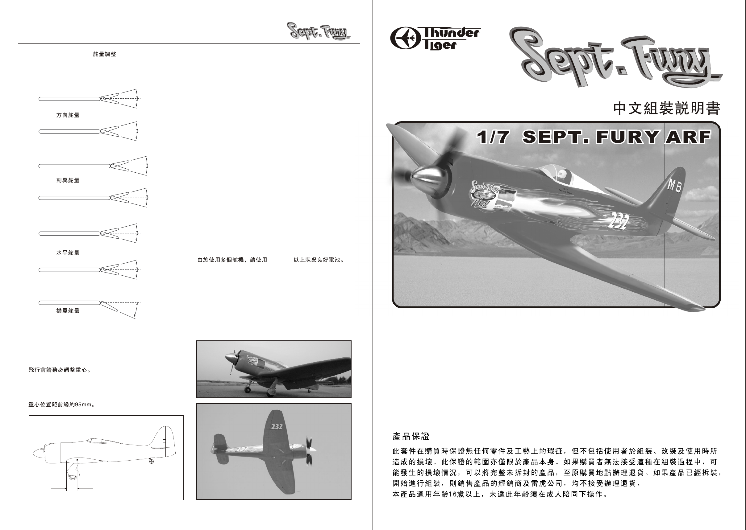
Control Throws
Set the control throws as followings for a starting point. After you
familiar with its flying characteristics then these control throw can
be tailored to fit your flying style.
Rudder-Low Rate
Rudder-High Rate
Aileron-Low Rate
Aileron-High Rate
Elevator-Low Rate
Elevator-High Rate
Flap
1"
1"
1 3/4"
1 3/4"
1/ 2"
1/ 2"
3/4"
3/4"
1/2"
1/2"
3/4"
3/4"
3"
Center of Gravity
IMPORTANT - Do not attempt to fly your model before
completing this very important section. A model that is not
properly balanced will be unstable and could cause serious
damage and/or injury. Adjust the battery location or add
weight as needed to achieve level balance.
Measure the C.G. while plane is dry. The balance point is
about 3 3/4"(95mm) behind the leading edge where there
is a panel line on fuselage.
Locate A Good Flying Site
Generally, the best place to fly your model is at an AMA
(Academy of Model Aeronautics) chartered club field. Your
local hobby dealer can tell you if there is such a club in your
area or write the AMA for information. It is also a good idea
to join this organization before flying your model since they
offer liability insurance that can protect you if your model
causes damage or injury to others.
Academy of Model Aeronautics
5151 East Memorial DR
Muncie, IN 47302-9252
www.modelaircraft.org
If there is not a chartered club field in your community,
you will need to find a large area free of obstructions, and
has a smooth grass or asphalt surface to be used as a
runway. For safetysake, it should be located well away from
houses, buildings, schools, power lines and airports. If you
will be flying within 6 miles of an airport, you should check
with the airport manager before flying your model.
A Note On Batteries
The batteries are the heart of your radio system. Make sure
you have fully charged batteries! With recharge-able
batteries, follow the manufacturers instructions to make
sure the batteries are fully charged, especial the first time
the radio is used. We would recommend you use larger
capacity (1000mAh) if you use high performance servos as
they will draw more current than ordinary servos.
1000mAH
Congratulations
Now that you have completed the assembly of your Sept.
Fury we feel that you have a very capable and good
looking sports scale plane. We hope that you will enjoy
this model and get many hours of flying pleasure from its
use. Thank you for purchasing this Sept. Fury from
Thunder Tiger and we look forward to providing you with
other great R/C products in the future.
Assembly Manual
No. 4573
Specifications:
Wing Span: 673/4" (1720mm)
Length: 60" ( 1525mm)
Weight: 5500g ( 12 lbs.)
Engine: .90 2C, 1.20 4C req'd
Radio: 5~8ch 6~8 servos req'd
This kit is guaranteed to be free from defects in material and workmanship at the date of purchase.
It does not cover any damage caused by use or modification. The warranty does not extend beyond
the product itself and is limited only to the original cost of the kit. By the act of building this userassembled kit, the user accepts all resulting in liability for damage caused by the final product. If the
buyer is not prepared to accept this liability, it can be returned new and unused to the place of
purchase for a refund. Neither your dealer nor Thunder Tiger Distributors, can accept kits for return if
construction has begun.
Notice: Adult Super Vision Required
This is not a toy. Assembly and flying of this product requires adult super vision.
Read through this book completely and become familiar with the assembly and flight of this airplane.
Inspect all parts for completeness and damage. fIyou encounter any prob lems, call us for help.
Unlimited Pylon Racer
Warranty
3 3/4"
(95mm)
JE6788 V2
124
Page 2
INTRODUCTION
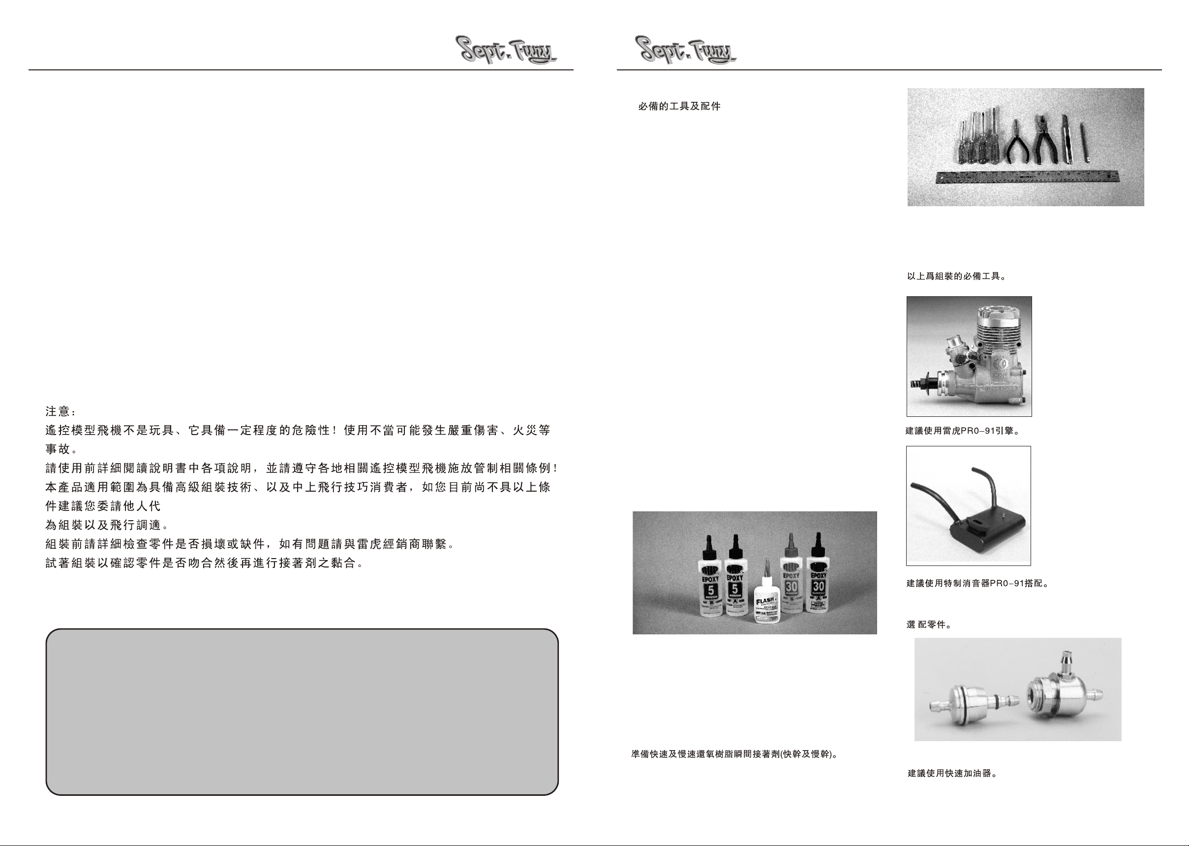
RECOMMENDED TOOLS & MATERIALS
Congratulations on the purchase of one of our finest ARFs to date. The ever-popular Sept.Fury piloted by Michael Brown
qualified in the Unlimited Class at 468.266 mph of the 2002 National Championships Air Race & Air Show, which was held
in Reno Stead Field. For more information please browse www.septemberpops.com for more information.
Thunder Tiger has teamed up with the Michael Brown Racing team to bring this legendary airplane to your hands; Thunder
Tiger is proudly to present the only officially licensed 1/7th replica of the "Sept.Fury" to all the R/C hobbyist alike worldwide!
It's a replica that has stayed true to the "Sept.Fury" in its purest form, pre-painted fiberglass fuselage and cowl, scale details
like panel line and retract well with gear door, etc. With it, you can now experience the thrill of piloting one of the best racing
planes in the history! Fly it low, fly it fast to experience the ultimate thrill and pylon racing excitement of the "Sept.Fury".
PRE-ASSEMBLY NOTES
The Sept. Fury is designed for advanced pilots and it requires advanced assembling and flying skill. Before you
begin, check the entire contents of your kit against the parts drawing and photos to make sure that no parts are missing
or damaged. This will also help you to become familiar with each component of your plane. If you find that any of the parts
are either missing or damaged, please contact Thunder Tiger Distributors for Customer Service.
Before beginning the assembly read the instructions thoroughly to give an understanding of the sequence of steps and a
general awareness of the recommended assembly procedures.
Trial fit each part before gluing it in place. Make sure you are using the correct part and that it fits well before assembling.
No amount of glue can make up for a poor-fitting part. Always apply Loctite ( not furnished) to all screws and nuts to
prevent them from loosening .
RECOMMENDED TOOLS & MATERIALS
Adhesives:
Instant setting Cyanoacrylate adhesive (thin CA)
Slow setting Cyanoacrylate adhesive (thick CA)
5-10 Minute Epoxy (fast)
20-30 Minute Epoxy (slow)
Tools:
Model knife, T-Pins, MASK tape
Small screwdrivers, medium screwdrivers
Scissors
Steel straight edge
Long nose pliers and diagonal cutting pliers
Drill and drill bits (1/16", 3/32", 3.4mm)
M4x0.7 Tap
Sanding block
Fine felt tip pen and soft lead pencil
Straight building board
R/C System:
6 Channel radio with 7 servos plus one retract servo
Five 12" extension wires.
one Y cords
Tools - Model assembly can be much easier if the proper
tools are used. Therefore, we have included in our
checklist to the left, a complete listing of all the tools we
used to assemble our prototype models. As you will
notice, many household tools can be utilized during
construction.
Engine-The Thunder Tiger
PRO-91is the ideal engines
for this airplane. This quietrunning engine is easy to
start, requires no special
break-in periods, easy to
maintain and will last for
years.
TABLE OF CONTENTS
Introduction................................................2
Recommended Tools & Materials ...............3
Parts Drawings........................................ 4-5
Parts Check List.........................................6
Wing................. ...................................7-10
Landing Gear......................................11-12
Rudder .......................................................17
Tail Gear ....................................................18
Engine........................................................19
Fuel Tank....................................................20
Radio..........................................................21
Cowling......................................................22
Engine:
2 cycle:91~1.08
4 cycle:1.2~1.5
Propeller:
Appropriate for engine type and preferred
performance
Adhesives - You will need two types of adhesives for the
Sept.Fury - Epoxy and Instant (cyanoacrylate) adhesives.
We recommend that you purchase both 5-minute and 30minute epoxy to cut down on assembly time, but you can
get by with only 30-minute epoxy if time is not important.
You will also need a small bottle of both "Thick" and "Thin"
instant CA adhesive.
Muffler (P/N TTR9791)
Most Pitts style mufflers
will fit this Sept. Fury .
However, we recommend
the use of Thunder Tiger
custom - made Sept. Fury
muffler with two exhaust
pipes that divert the smoke
in to the two concavities of
the fuselage to obtain a
more scale- like apperance.
This muffler fits TT and OS.
60~.90engines.
ITEMS YOU MAY NEED
Fuselage..................................................13
Tail......................................................14-16
Decal .........................................................23
Balance......................................................24
2
TTR11 15 - Precision Fueler Valve
3
Page 3
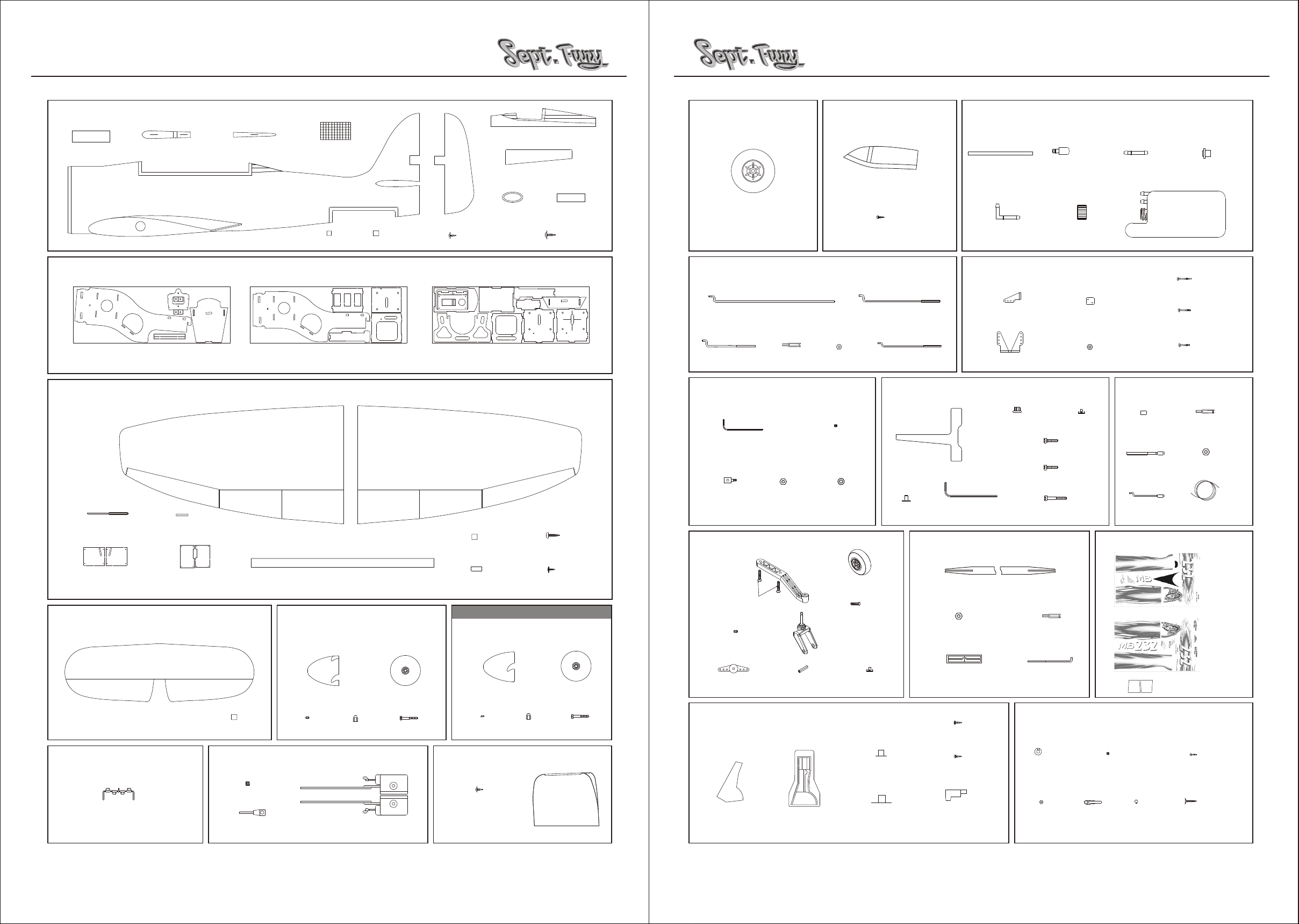
PARTS DRAWINGS PARTS DRAWINGS
AS6429 Fuselage
Coveling 200X80mm
VT Lower Trailing Edge (1)
AS6428 Plywood Parts
Plywood Parts (A)
AS6430 Main Wing
Fuselage(1)
VT Upper Trailing Edge (1)
Fiberglass Cloth (1)
Doubler(28)
Plywood Parts (B)
CA Hinge (3)
Rubber Band (2)
Rudder (1)
2x8mm Washer Wood Screw (24)
Plywood Parts ( C)
FRP Cockpit (1)
FRP Tail Cover (1)
FRP Tube(1)
2.3X12mm Washer Wood Screw (4)
No. 3299 Wheel
Wheel (2)
AS6435 Pushrods
Throttle Pushrod (1)
Flap Pushrod (2)
Clevis(4)
PE0009 EZ Connector
AS6432 Canopy
Canopy (1)
2x5mm Wood Screw (4)
Retract Pushrod (2)
M2 Nut (4)
Aileron Pushrod (2)
No. 3012 Anti-Vibration Engine Mount
No.3265 Fuel Tank
Silicone Tube (1)
90-degree Nipple (1)
Crank Weight (1)
Cap (1)
AS6441 Control Horn
Control Horn (S/4)
Control Horn (L/2)
Back Plate (4)
M2 Nut (2)
Straight Nipple (1)
2x30mm Machine Screw (2)
2x22mm Machine Screw (4)
2x15mm Machine Screw (4)
Fuel Stopper (1)
480cc T ank (1)
AS6434 Pull-Pull System
Joiner Wire (2)
Aileron Servo Case (L/1, R/1)
Joiner Tube (2)
Flap Servo Case ( L/1, R/1)
AS6431 Horizontal Tail
Horizontal Tail (1)
Left Wing (1) Right Wing (1)
FRP Wing Joiner Tube (1)
No.3291 Aluminum Spinner
(3-Blade)
Back Plate (1)
Spinner Bolt (1)
CA Hinge (6)
Aluminum Spinner (1)
Bushing (1)
Adaptor (1)
CA Hinge (14)
Dowel (4)
3x20mm Wood Screw (2)
2.3x12mm Washer Screw (16)
OPTINAL PARTS
No. 3290 Aluminum Spinner
(2-blade)
Aluminum Spinner (1)
Bushing (1)
Adaptor (1)
Back plate (1)
Spinner Bolt (1)
1.5mm Hex Wrench (1)
EZ Connector (1)
M2 Nut (1)
3x3mm Setscrew (1)
M2 Washer (1)
AS6438 Scale Tail Gear
4x20mm
Sink Head Screw (2)
Sink Head Screw (1)
3x5mm Setscrew (1)
Steering Horn (1)
Wheel Spacer (1)
Tail Wheel Fork (1)
AS6437 Retract Decoration
Tail Wheel (1)
2.6x26mm
Blind Nut(2)
Rubber (8)
Mounting Beams (2)
T Washer (8)
4mm Hex Wrench (1)
AS6439 Elevator Linkage Set
Elevator Wood Pushrod (1)
M2 Nut (2)
Pushrod End Retainer (1)
2.6x5mm Wood Screw (2)
Blind Nut (4)
6/32 x 20mm Socket Cap Screw (4)
4x 20mm Socket Cap Screw (4)
5x40mm Socket Cap Screw (4)
AS6436 Decal
Clevis (2)
Threaded Pushrod (2)
AS6440 Hardware Set
Brass Tube (8)
Threaded End (4)
Z-Bend End (2)
Silver Decal (L/1,R/1)
Clevis (4)
M2 Nut (4)
Wire (3.6M/1)
Decal A (1)
Decal B (1)
AS6425 Elevator T orque Wire
Torque Wire (1)
No.3009 Superlite Retract
3x3mm Setscrew (2)
Wheel Axle (2)
Retract ( L/1, R/1)
AS6433 Cowling
2.3x12mm
Washer Wood Screw (4)
Cowling (1)
Wheel Door (L/1, R/1)
Wheel Well (L/1, R/1)
Upper Retainer A (2)
Upper Retainer B (2)
2x5mm Wood Screw (4)
Lower Retainer (2)
54
Collar (2)
M2 Nut (2)
3x3mm Setscrew (2)
Ball End (2)
Ball (2)
2x8mm Machine Screw (2)
3x16mm Sink Head Screw (8)
Page 4
PARTS CHECK LIST
WING
Kit Contents:
FRP Fuselage (1)
FRP Cockpit (1)
FRP Tail Cover (1)
FRP Cowling (1)
FRP Wing Joiner Tube (L/1)
FRP Tube (S/1)
Left Wing (1)
Right Wing (1)
Rudder (1)
Horizontal Tail (1)
Elevator (L/1, R/1)
Aileron Servo Case (L/1, R/1)
Flap Servo Case (L/1, R/1)
Plywood Parts(A)
Plywood Parts(B)
Plywood Parts(C)
VT Lower Trailing Edge (1)
VT Upper Trailing Edge (1)
Doubler(28)
Dowel (4)
Covering (1)
Fiber Cloth (1)
Joiner Wire (2)
Joiner Tube (2)
Rubber Band (2)
CA Hinge(23 )
2x5mm Wood Screw(8)
2.6x 5mm Wood Screw (2)
2x8mm Washer Wood Screw(24)
2.3x12mm Washer Wood Screw (24)
3x20mm Wood Screw (2)
2x8mm Machine Screw (2)
2x15mm Machine Screw (4)
2x22mm Machine Screw (4)
2 x30mm Machine Screw (2)
3x16mm Sink Head Screw (8)
4x20mm Sink Head Screw (2)
3x3mm Setscrew (5)
EZ Connector(1)
M2Washer(1)
Torque Wire (1)
M2 Nut (15)
Clevis (10)
Collar (2)
Ball End (2)
Ball (2)
Al. Spinner (3-blade, 1)
Backplate (1)
Bushing (1)
Adaptor (1)
Spinner Bolt (1)
Engine Mounting Beam (2)
T Washer (8)
Rubber (8)
Blind Nut (4)
Socket Cap Screw 5mm x 40 (4)
Hex Wrench 4mm (1)
Hex Wrench 1.5mm (1)
Socket Cap Screw 6/32 x 20mm (4)
Socket Cap Screw 4x20mm (4)
Tank (1)
Silicone T ube (1)
Straight Nipple (1)
90-degree Nipple (1)
Crank Weight (1)
Fuel Stopper (1)
Fuel Cap (1)
Throttle Pushrod (1)
Retract Pushrod (2)
Flap Pushrod (2)
Aileron Pushrod (2)
Elevator Wood Push Rod (1)
Elevator Pushrod Retainer (1)
Thread Pushrod(2)
Control Horn (L/2)
Control Horn (S/4)
Backplate (S/4)
Canopy (1)
Wheel Door (L/1, R/1)
Wheel Well (L/1, R/1)
Upper Retainer A (2)
Upper Retainer B (2)
Lower Retainer (2)
Retract (L/1, R/1)
Wheel Axle (2)
Wheel (2)
Brass Tube (8)
Straight Threaded End (4)
Z Bend Threaded End (2)
Wire (2)
Tail Gear (1)
Tail Wheel Fork (1)
Wheel Spacer (1)
Steering Horn (1)
3x5mm Set Screw (1)
Tail Wheel (1)
Blind Nut (2)
2.6X26mm Sink Head Screw (1)
Decal A (1)
Decal B (1)
Silver Decal (2)
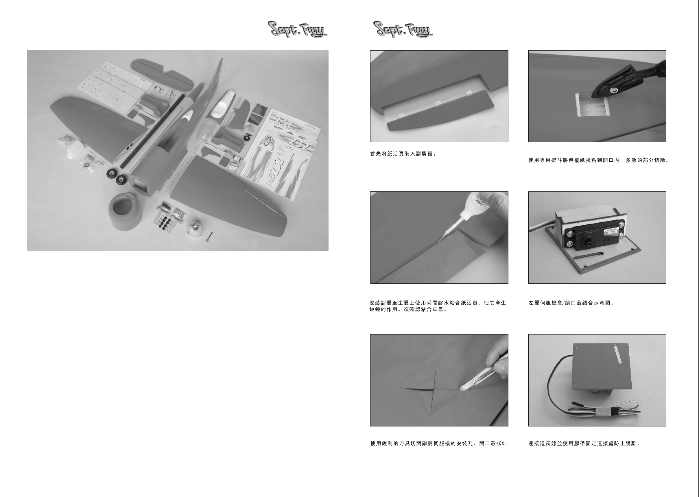
1. Glue the CA hinges in aileron first.
2. Next attach the aileron in place then apply CA on both
sides. Make sure aileron is firmly glued.
3. Locate the aileron servo well then use a hobby knife to
cut an "X".
4. Using a sealing iron to tack down the covering inside
the servo well. Trim the excess covering away.
5. Locate the left wing servo case / hatch cover; secure
the aileron servo as shown.
6. Connect an extension wire for Aileron servo, heatshrink or tape the connectors to prevent from loosening.
6
7
Page 5

WING WING
Flap II
Flap I
7. Use Throttle Pushrod to guide the wire through the
wing panels. Fix the wire with mask tape to prevent from
falling back into wing pannel.
8. Link aileron servos wires to CH1 on receiver. Make
sure the direction is correct. Set the servo horn in the
neutral then secure the servo horn screw next secure
the servo case in place with four 2.3x12mm washer
wood screws.
10. If you would use Flap function then proceed the
following steps. If not then skip to step 24. Do the same
procedure for Flap Servo Case. (Left Flap Servo Case
shown) and thread the wire through the wing panel and
tape the wire end on wing root.
11. Temporally secure the Flap Servo Case in place
with 2.3x12mm Washer Wood Screws.
13. Next cut away the covering between Flap I and Flap II.
14. Carefully cut away the flap from trailing edge.
16. Locate the joiner wire and guide tube. Make mark at
the center of the joiner side of the Flap I and Flap II.
17. Carefully drilling the joiner side at mark. Note that it
is angle at the joiner side please drill the hole perpendicular to the surface. Drill 2.5mm hole on Flap I and 2mm
hole on Flap II.
9.Please note that the aileron is thick; carefully drill the
(5/64")2mm holes and make sure the back plate is flush
with the hinge line at the other side of aileron. Secure
the control horn in place with 2x22 machine screws.
Trim away the excess screw from the backplate. Install
the pushrod with metal clevis, M2 nut and thread on a
piece of silicone tube asshown.
12. Carefully cut away covering. The knife may lean
against the flap then carefully cut along with the flap
leading edge.
15. Iron the covering at the trailing edge.
Flap II
Flap I
18. Insert guide tube in Flap I and light apply CA glue.
Glue threaded end of joiner wire in Flap II, also apply a
drop of CA glue. Cut two hinge slots and glue CA hinges
in place.
98
Page 6

WING
LANDING GEAR
19. Secure control horn on Flap I with 2x15mm machine
screw. Note the control horn should away from the edge
at least 8mm. The 8mm is to clear the rib located at the
center of both flaps.
20. Leave 0.5mm clearance between ribs and flap then
draw the hinge line. Next cut hinge slots to accommodate
the hinges on flaps.
22. Repeat the same procedure on the right wing. Link
two aileron servo wires with Y cord and plug to CH1 on
receiver. Plug the left flap to Ch6 and right flap to Ch7.
Refer to your radio manual and set up Flap.
Here is the set up procedure if using FF9 :
23. Epoxy the dowels at wing root in place as shown.
24. Locate the plastic retract well; trim along the molded
line.
26. Place the retract in place and drill 5/64"(2mm) holes
on the retract mount.
27. Locate the retract pushrod and ball end, thread the
ball end as shown. The Z-bent end to the center of the
ball end is about 218mm.
21.Join two flaps then insert them to the wing in place.
Make sure there is no contact with each other then apply
CA at the hinge area. Move the flap again and make sure
it works smoothly.
1.Reset first.
2.Flap ATV 140% 140%
3.AUX1 ATV 140% 140%
4.Airbrake on Flap 100%
5.PMIX7 AUX1-AUX1
Position 1: 0%
Position 2: 0%
Position 3: 0%
Position 4: 45%
Position 5: 90%
6.Trim the two flaps at same throws by adjusting the trim
knob and pushrod if necessary.
25. CA the retract well in place, trim the excess plastic
so it is level with the wing root.
28. Insert the pushrod from wing root then connect to
retract. Note: The ball end with "Tiger" side should face
upside of wing.
1110
Page 7

LANDING GEAR FUSELAGE
29. You may need to trim the wires of retract so the
wheel axle is lever to the wing root. Secure the retract in
place with four 3x15mm Sink Head Screws. Flats should
be ground on the landing gear legs for the setscrew to
prevent the wheel axle from rotating under load.
32.Sand the upper retainer B and place it in the strut coil
then apply CA on retainer. Next place the wheel door in
place, the retainer will be glued on wheel door precisely.
35.Install the wheel and secure collar with 3x3mm set screw.
Make sure wheel rotates freely.
38. The side frame is either marked L or R.Make sure L
is at left side and R is at right side. Always trial fit all
wood parts before you glue it. Suggest to glue the one
side frame in place first, next the other side frame with
servo tray at the same time. Fuel tank retainer and
retract servo mount strips at the last.
30.Locate and trim the wheel door retainers as shown.
31. Trim the retract door to fit the retract well.
33. Secure the retract door with the retainers ( A, B ) at
the strut coil with 2.6x5 mm wood screw.
34. Secure the lower retainer on wheel door with two
2x5mm wood screws.
36. Locate the two side frames and rear bulkhead. Trail
fit in the fuselage. Make sure the side frame insert to
the front bulkhead properly. Make mark on fuselage.
Remove all wood parts then use 200 grit sandpaper to
sand where you marked. Epoxy the rear bulkhead in
place.
37.Locate servo trays and servo tray doubler then glue
the doubler in place. There are two fuel tank frames.
Make sure the shorter slot is in the front and longer slot
is in the rear.
39. Glue the short guide tube in fuselage.
40. Trail fit the two wing halves and join them with the
fiberglass tube. Never push too hard as it may damage
the tube-stop rib inside the wing panel. Trim holes or
dowels might be necessary to get a good fit .
1312
Page 8

TAIL
41. Locate the hole that is located at the bottom wing
between retract the flap servo hatch. Drill a 5/64" (2mm)
hole through the fiberglass tube of the main wing halves,
and make sure they are firmly close to the fuselage then
secure 3x20mm wood screws. Main wing is removable
for convenient in transportation. For best performance,
epoxy two wing halves is strongly recommended.
43.Epoxy the firewall in place. You may insert the firewall
to L sideframe then push in the other side. Make sure the
firewall with right thrust angle as shown.
46. Trial fit the battery box, then epoxy the battery box
and bottom reinforced ply in place. When cured, lightly
apply epoxy on all firewalls area as well as the battery
box so the plywood could be fuel-proof. Just mix the
epoxy with no more that 50% mix of alcohol then brush
on firewall.
TAIL
49.Carefully use hobby knife to cut lines inside the lines
about 1~2mm. Remove covering as shown. Never cut
too deep to hurt the balsa planking.
44.Assemble the Anti-Vibration Engine Mount.
TAIL
50.Cut away the covering of leading edge at the root of
elevator where the torque rod is going to be installed.
CA three hinges in elevator at this time.
47.Remove the balsa insert from the vertical fin. Then
use flat file to file the in side of the tail to get a smooth
surface.
42.Sandwich the three firewalls together; note the cross
laser cut mark should be on the top and smallest one at
the bottom.
14
45.Install the Anti-Vibration Engine Mount in place with
5x40mm Socket Cap Screw and Blind Nut. You just
screw in the cap screw then the blind nut will punch into
the firewall.
48.Trial fit horizontal tail in fuselage, center it then make
marks on tail at four sides.
51.Trail fit the elevator on tail with torque rod installed.
Do not glue at this step. When satisfied, remove the
elevator and torque rod.
15
Page 9

TAIL
52.Sand the tail saddle to increase the roughness as well
as inside of the flange as the fiber cloth will be applied
later.
55. Apply 30 min epoxy at the glue area and carefully cote
the fiber cloth.
58. Apply a small tube onto the clevis then connect the
elevator pushrod to the elevator torque rod. A flat head
screwdriver will help snapping the clevises onto the
torque rod link. Trim the elevator center notch for enough
throws (down) as page 24 shown.
RUDDER
61. Glue Vertical Fin Bracket in place and make sure the
upper one and lower one are in line. Apply epoxy at
torque rod hole next install the elevator in place. CA all
hinges and make sure elevator is firmly secured.
53. Insert and center the tail in place. Use books or boxes
to support tail ends make sure it is level to the main wing.
You may need to file the flange to get a good fit. Use
furnished rubber bands to reduce the gap and fix the tail
in place. Apply thick CA or epoxy when satisfied.
54.Locate the fiber cloth then cut into two pieces at about
100 x 80mm (4 " x 3").
56.Lubricant oil to the hinges of elevator torque rod. You
may spray WD-40 on the hobby knife then use the knife
tip to contact the torque shaft and the oil will go into the
hinge. Epoxy the elevator joiner in place.
57.Locate the elevator pushrod parts as shown, epoxy
the plywood inside the wood rod at two ends with wires.
Thread the M2 nuts and clevises and make sure the
whole elevator pushrod has no free play. Note the
orientation of the pushrod and clevis.
59.Install elevator servo, note the servo horn orientation.
Then adjust the clevises to make sure elevators are level
when servo is in neutral position. When satisfied, remove
the elevator pushrod temporarily and secure M2 nuts and
clevises firmly.
RUDDER
60.Trail fit the Vertical Fin Bracket in the Vertical Fin, you
may need to sand to fit in place. When satisfied, use
furnished covering and iron on the covering as shown.
62.CA the Rudder on Vertical Fin with three CA hinges.
Next install the control horns on the rudder with two
2x30mm machine screws and M2 nuts.
63.Locate the straight threaded end, brass tube, M2 nuts,
clevises and wire. Cut wire in length 90mm. First thread
the M2 nut and clevis then secure the M2 nut on clevis.
Then route the wire through the tube and make it a circle.
16
17
Page 10

TAIL GEARTAIL GEAR
64. Next thread the wire through the clevis linkage then
tread to the tube again.
65.Make the other circle as shown.
67. Drill the pull-pull wire exit hole and thread the wire
into fuselage to the rudder servo. Do the same way to
servo end and use Z bend end rod. Do not crimp the
brass tube at this moment until tail gear pull pull wires
are ready.
TAIL GEAR
68.Locate the tail gear mount, doublers then glue them
together then press the Blind Nut in the hole. It will be
easier to use hammer or mice.
70. Locate the tail gear bag, and assemble the tail gear
as shown. Note the orientation of steering arm, trim the
outer hole away as it is too long to install in the tail.
Secure steering arm in place with 3x5mm set screw.
71. Secure the tail gear assembly on the tail gear mount
with 4x20mm sink machine screws.
73. Adjust the threaded end at the servo end to get better
tension of the four wires and make sure both rudder and
tail gear are in line with each other. Crimp the tubes when
satisfied.
74. Locate the bottom tail cover, make the opening
according to the tail gear.
66.Adjust the wire to make the circle as small as possible
then use the pliers to crimp the wire firmly.
18
69. Secure the tail gear mount right in the front with four
2x8mm washer wood screws.
72. Do the same procedure of the pull-pull wire on tail
gear.
75. Trim the tail cover and fit in place. Drill eight 1.5mm
holes then glue doublers at the hole area. It might be
needed to sand the doubler to adapt to the curve surface.
Drill the holes again on doublers then secure the bottom
tail cover with 2x8mm washer wood screws.
19
Page 11

FUEL TANK
ENGINE
76.Place the Engine (Thunder Tiger PRO-91 Shown) in
the Engine Mount then proceed to make mount hole
marks on the engine mount where drive washer is 53/4"
(147mm) to the firewall.
78.Install the Sept. Fury Exclusive Muffler(TTR9791),
which contains 2 angled exhaust pipes and aim to the
concavity of the fuselage for true scale looking.
RADIO
81. Locate the retract servo tray, glue the doubler as
shown. Then, install the retract servo on the servo tray.
84. Secure battery box cover with four 2x8mm washer
wood screws.
77. Remove the engine and engine mount. Drill the 3.4mm
holes based on those marks then tap the hole with M4x0.7
thread tap. Connect throttle pushrod then secure the engine
with M4x20mm socket cap screws. Make a Z bent on throttle
pushrod as indicated.
Locate the fuel tank and its accessories. Assemble the
tank as shown. Install the fuel tank in place, connect the
fuel lines and exit from the firewall for enough length to
carb and muffler.
79.Install T tube fitting and fuel tube plug as shown, this
will help you to know fuel is full when pumping.
80. Install the EZ connector on the throttle servo horn
with M2 washer and M2 nut. Afterwards, thread the
throttle pushrod through the EZ connect and secure the
servo horn on the servo. Adjust the servo with the radio
on, once satisfied with the result, proceed to secure the
throttle pushrod with a 3x3mm set screw.
82. Secure the whole assembly in place with four 2.3x12mm
washer wood screws. Next secure two Steel Balls on the
servo horn with 2x8mm machine screw and M2 nuts. The
distance between two balls is 24mm. Fine adjust the retract
pushrod, and make sure the ball link with "Tiger" is facing
up. Switch on the retract gear to make sure the retract gear
works smoothly.
83. Place a battery in the battery case; use double side
tape to secure it in the fro nt of battery case. You can use
the excess servo tray plywood to make a block to hold
battery in place. It requires an extension wire to connect
to the switch harness. Approximately 300-350g of weight
will be added in the front of the battery case. See balance
section in page24 and add proper weights to get right CG.
85. Connect all servo wires to the receiver; wrap the
receiver with foam to fully protect the receiver. Insert
receiver between frame and fiberglass wall in fuselage.
86.Route the antenna along the fuselage and exit at the
tail gear opening. Tape the wire in place as shown.
20
21
Page 12

COWLING
DECAL
87. Install the engine cowling; first glue the plywood
doublers inside the fuselage at where hole is . Trial fit
the cowling in place and temporarily secure it with mask
tape. Drill 1/16"(1.5mm) at the place where doublers
are.
88. Drill needle valve extension wire exit hole. When
satisfied, secure the cowling in place with 2.3x12mm
Washer Wood Screws.Suggest to install Precision Fueler
(TTR1115) for easy fueling.
90. Suggest to file the cowl located near the vent of
carburetor as shown, the engine will get enough air and
run smoother if you install a 2 stroke engine.
92.Refer to the box label then apply all decals. Suggest
to join the fire decals together before applying on
fuselage.
93.The photos shown is the decal at retract gear door.
94.Trial fit the upper Cockpit on fuselage, drill eight 1/16"
(1.5mm) holes and glue small plywood doublers inside
the fuselage at the holes area. Drill the doublers again
and secure the cockpit in place with 2x8mm washer wood
screws.
89. Install the propeller and furnished spinner. What we
used here is Master Airscrew 13x8.
22
91. Apply instrument panel in the cockpit. Next trim the
canopy and trial fit the canopy on the cockpit. Glue the
plywood doublers and drill four 1/16" ( 1.5mm ) holes.
Secure the canopy with four 2x5mm washer wood screws.
Pilot shown is not included.
95.You may need to remove the cowling and apply silver
decal as shown.
Your Sept. Fury is now ready to fly, carefully set up the
control throws and balance your plane well before each
and every flight; never take chances or rush fly your
Sept. Fury.
23
 Loading...