

Page 1
EVCC 2.4 Quick-Start Guide
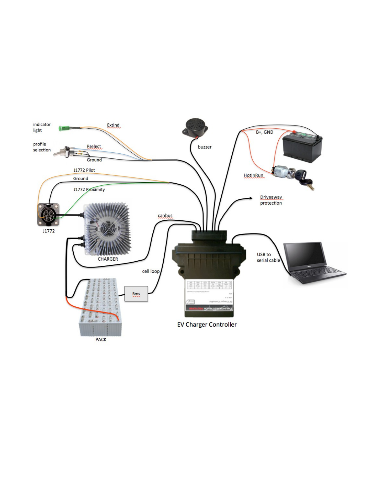
The Electric Vehicle Charger Controller (EVCC) integrates charger CANBUS control, J1772 Level 2
charging, and BMS head end functions. Charge parameters are configured, saved in nonvolatile memory, and
used when charging to control a CAN enabled charger. The EVCC connects to analog “cell loop” Battery
Management Systems (BMSs) as well as CAN enabled BMSs.
The EVCC is configured using a simple serial interface. This interface is used for configuration and
debugging, but is not required for normal operation. Diagnostic commands are supported to verify proper
wiring, to trace CANBUS messages, and to retrieve charging history.
The EVCC supports the SAE J1772 standard. J1772 defines the physical connector and protocols used
between the charging station (known as the “Electric Vehicle Service Equipment”), and the Electric Vehicle.
The J1772 Proximity signal is used to determine if the charger plug is present. The J1772 Pilot signal is used
to start and stop charging (by enabling and disabling the contactor in the EVSE). The J1772 Pilot duty cycle
Figure 1 – EVCC System Diagram
Page 2

is measured and can be used to limit charging current. “Driveaway protection” is supported so that the EV
cannot be driven if the charge cable is still plugged in.
The EVCC supports several CAN enabled chargers, including the Thunderstruck TSM2500 charger. Charge
voltage, charge current and overall charge time are controlled completely by the EVCC over the CAN
interface to the charger. A constant current/constant voltage charge curve is supported for Lithium Batteries;
and a three phase charge cycle is supported for Lead Acid Batteries.
The EVCC supports up to four parallel chargers for faster charging. When multiple chargers are configured,
they are individually CAN addressed. Work is divided evenly between the chargers and statistics are
gathered and recorded on each charger individually.
For complete documentation see http://www.thunderstruck-ev.com/tsm2500-and-charge-controller.html.
Page 3

The figure below shows the EVCC pinout.
A B C D E F
1
2
3
12V GND Ext_Ind Loop1 12V_Sw CANH
Ignition GND Pilot Loop2 GND CANL
GND P_Select Proximity PackFault OKToDrive reserved
Figure 2 – EVCC Pinout
Bringup Checklist and Troubleshooting Hints
EV Installation
1) Connect 12V, GND, Ignition
2) Connect Proximity, Pilot, GND
3) Connect P_Select to a selector switch (and resistor array), if used
Verify Analog Inputs
1) Type “measure” with no parameters to get the expected readings for each analog input. Note that if there is
not a good ground connection between J1772 ground and EV chassis ground that the J1772 readings will be
erratic.
2) Verify Cell Loop, using “measure loop”
a. Disconnect J1772 plug if connected
b. Verify readings with cell loop open and closed.
3) Verify Proximity, using “measure proximity”
a. Disconnect cell loop, if connected
b. Verify readings with charger plug disconnected, connected, and unlocked.
4) Verify Cutback, if used, using “measure pselect”.
a. Verify readings with different pselect switch settings.
Verify J1772
1) Connect Cell Loop to CellLoop1 and CellLoop2.
2) Plug in J1772 Plug
3) The EVCC should attempt to start charging (LED blinks once per second).
4) Assuming the CAN bus is not connected to the charger yet, the charge cycle should stop after 10-15 seconds.
5) Remove 12V from Ignition, unplug the J1772.
6) Verify the “autostart” by plugging in the J1772 plug. The EVCC should power up and go into the Charge state.
7) For debugging, use “trace state” to verify that the EVCC attempts to start charging if the J1772 plug is in and
the user powers up the EVCC.
Verify Charger and CAN
1) Connect Charger to J1772, connect CAN between Charger and EVCC.
2) Verify proper installation of the CAN termination resistors. Measure between CANH and CANL to verify that
the resistance of 60ohms. Remember that if the internal EVCC termination resistor is used, that it must be
powered up in order to make this measurement.
3) Now verify that when a charge cycle is started, that messages are exchanged between EVCC and Charger.
(Use “trace charger” or “trace can” to log the messages).
4) If the pack is not yet connected to the Charger, the charge cycle will stop after a minute.
Systems Test
1) Verify all systems functions.
 Loading...