


Model 2900 System Manual
Thunder Scientific Corporation

Model 2900 Humidity Generation System
Document #OM2900 - Edition 2.0
OPERATION AND
MAINTENANCE MANUAL

Model 2900 Humidity Generation System
Thunder Scientific®
70% PROPYLENE GLYCOL 2 bottles for your system
Corporation
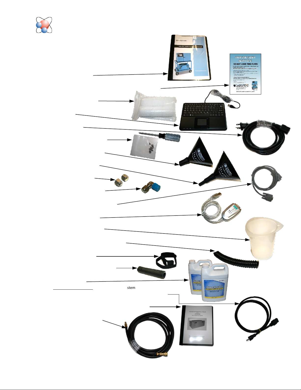
2900 Item Check List
1. Certificate of Calibration (In Chamber)
2. Quick Start Guide
3. HumiCalc® with Uncertainty Software Download
4. Chamber Port Plugs
5. Keyboard
6. Power Cable
7. Torx Driver with Screws
8. Reservoir Fluid Funnel
9. Chamber Fill Funnel
10. Plugs, ¼ Swagelok
11. Elbow, ¼ Tube x ¼ NPT
12. Communication Cable (DB9)
13. USB Serial Converter
14. Plastic Beaker 1000ML
15. 3/8" Plastic Elec Flex Conduit 36”
16. Velcro Straps 2 Ea.
17. Temp Probe or UT Cap Tool
18. Chamber Fluid
1. Optional Equipment – Air Compressor Power Cable
2. ACS2520 – Air Compressor System Manual
3. Air Hose – On Air Box
4. ACS Remote Control Cable
Thunder Scientific Corporation Web: www.thunderscientific.com
623 Wyoming Blvd. SE E-mail: support@thunderscientific.com
Albuquerque, NM 87123 Phone: 1-800-872-7728

IMPORTANT
NOTICE
IMPORTANT
NOTICE
DO NOT LOSE THIS FLYER
Go to this website to register your Model 2900 Humidity Generator and
download your software for FREE.
https://www.thunderscientic.com/product_registration
Once you have registered your Model 2900 Humidity Generator, click the link on the same page, labeled
Click here if you need to download your FREE software. Click here if you need to download your FREE software.
Or go to this URL https://www.thunderscientic.com/software/
Next, click on which software type you need, and go to that page, then click the Download Now button.
After downloading your software, open the ZIP le and install your software.
This is a trusted download link form Thunder Scientic, Thank You for your purchase.
For:
HumiCalc with Uncertainty Software Package Download
®
IMPORTANT CONTROLOG PASSWORD INFORMATION
User: 2900
Manager: 2900.1
Administrator: Contact Thunder Scientic Technical Support
(1-800-872-7728 or support@thunderscientic.com)
Humidity Generation and Calibration Equipment
®
The Humidity Source
Thunder Scientific Corporation
623 Wyoming Blvd SE
Albuquerque, NM 87123-3198
U. S. A.
Model 2900
www.thunderscientific.com

Suomi
English
Tämä tuote noudattaa WEEE-direktiivin (2002/96/EY)
merkintävaatimuksia. Kiinnitetty etiketti osoittaa, että tätä
sähkö-/elektroniikkalaitetta ei saa hävittää kotitalousjätteissä.
Tuoteluokka: Viitaten WEEE-direktiivin liitteessä I mainittuihin
laitteisiin, tämä tuote on luokiteltu luokan 9 “Tarkkailu- ja
ohjauslaitteet” -tuotteeksi.
Ei saa heittää kotitalousjätteiden mukana!
Palauta tarpeettomat tuotteet ottamalla yhteyttä valmistajan
websivustoon, joka mainitaan tuotteessa tai paikalliseen
myyntitoimistoon tai jakelijaan.
Dansk
Dette produkt er i overensstemmelse med kravene om afmærkning
i WEEE-direktivet (2002/96/EC). Det påhæftede mærkat angiver,
at du ikke må bortskaffe dette elektriske/elektroniske produkt via
husholdningsaffald.
Produktkategori: Med reference til kravene i WEEE-direktivets
bilag I klassificeres dette produkt som et produkt til “overvågning
og kontrolinstrumentering” i kategori 9.
MÂ ikke bortskaffes via husholdningsaffald!
Hvis du vil returnere uønskede produkter, skal du besøge
producentens websted, som vises på produktet, eller den lokale
forhandler eller distributør.
This product complies with the WEEE Directive (2002/96/EC) marking
requirements. The affixed label indicates that you must not discard
this electrical/electronic product in domestic household waste.
Product Category: With reference to the equipment types in the
WEEE Directive Annex I, this product is classed as category 9
“Monitoring and Control Instrumentation” product.
Do not dispose in domestic household waste!
To return unwanted products, contact the manufacturer’s web site
shown on the product or your local sales office or distributor.
Français
Ce produit est conforme aux normes de marquage de la directive
DEEE (2002/96/CE). La présence de cette étiquette indique que
cet appareil électrique/électronique ne doit pas être mis au rebut
avec les déchets ménagers.
Catégorie de EEE : Cet appareil est classé comme catégorie 9 parmi
les « instruments de surveillance et de contrôle » en référence aux
types d’équipements mentionnés dans l’Annexe I de la directive DEEE.
Ne pas éliminer avec les autres déchets ménagers !
Pour renvoyer les produits indésirables, contacter le site Web du
fabricant mentionné sur le produit, ou son distributeur ou bureau de
ventes local.
Español
Este producto cumple la Directiva WEEE (2002/96/EC) sobre
requisitos de las marcas. La etiqueta que lleva pegada indica
que no debe desechar este producto eléctrico o electrónico con
los residuos domésticos.
Categoría del producto: con referencia a los tipos de equipo
del anexo I de la Directiva WEEE, este producto está clasificado
como categoría 9 de “Instrumentación de supervisión y control”.
¡No lo deseche con los residuos domésticos!
Para devolver productos que no desee, póngase en contacto con
el sitio Web del fabricante mostrado en el producto, o con la oficina
de ventas o distribuidor local.
PN 2566073, 1/2006
Deutsch
Nederlands
Dieses Produkt stimmt mit den Kennzeichnungsanforderungen
der WEEE-Richtlinie (2002/96/EC) überein. Das angebrachte
Etikett weist darauf hin, dass dieses elektrische/elektronische
Produkt nicht in Hausmüll entsorgt werden darf.
Produktkategorie: In Bezug auf die Gerätetypen in Anhang
I der WEEE-Richtlinie ist dieses Produkt als Kategorie 9
“Überwachungs- und Kontrollinstrument” klassifiziert.
Nicht in Hausmüll entsorgen!
Zur Rückgabe von unerwünschten Produkten die auf dem
Produkt angegebene Website des Herstellers oder die zuständige
Verkaufsstelle bzw. den zuständigen Fachhändler konsultieren.
Italiano
Questo prodotto risponde ai requisiti sull’etichettatura stabiliti
nella Direttiva RAEE (2002/96/CE). Il simbolo apposto indica che
non si deve gettare questo prodotto elettrico o elettronico in un
contenitore per rifiuti domestici.
Categoria del prodotto: con riferimento ai tipi di apparecchiature
elencate nell’Allegato 1 della Direttiva RAEE, questo prodotto
rientra nella categoria 9 “Strumenti di monitoraggio e di controllo”.
Non gettare in un contenitore per rifiuti domestici.
Per restituire prodotti non desiderati, visitare il sito Web del
produttore riportato sul prodotto o rivolgersi al distributore o
all’ufficio vendite locale.
Dit product voldoet aan de merktekenvereisten van de AEEArichtlijn (2002/96/EG). Het aangebrachte merkteken duidt erop dat
dit elektrische/elektronische product niet met het huishoudelijk
afval mag worden afgevoerd.
Productcategorie: Met betrekking tot de apparatuurcategorieën
van bijlage I van de AEEA-richtlijn, valt dit product onder categorie
9 ‘meet- en controle-instrumenten’.
Niet afvoeren met huishoudelijk afval!
Om ongewenste producten te retourneren, neemt u contact op
met de website van de fabrikant die op het product staat vermeld,
of met uw plaatselijke verkoopkantoor of distributeur.
Svenska
Denna produkt uppfyller märkningskraven enligt WEEE Directive
(2002/96/EC). Märkningsetiketten anger att du inte får kassera denna
elektriska/elektroniska produkt tillsammans med vanliga hushållssopor.
Produktkategori: Med hänvisning till utrustningstyperna i
WEEE Directive Annex I, är denna produkt klassad som kategori 9
“Monitoring and Control Instrumentation” (Instrument för
övervakning och styrning).
Får ej kasseras tillsammans med vanliga hushållssopor!
Returnera ej önskvärda produkter genom att gå till tillverkarens
webbplats, vilken anges på produkten, eller till det lokala
försäljningskontoret eller distributören.
Português
Este produto está em conformidade com as exigências de rotulagem
da Directiva WEEE (2002/96/EC). O rótulo afixado indica que o
utilizador não deve deitar este produto eléctrico/electrónico fora
juntamente com o lixo doméstico.
Categoria do produto: No que se refere aos tipos de equipamento listados no Anexo I da Directiva WEEE, este produto está classificado como
produto da categoria 9, “Instrumentação de monitorização e controlo”.
Não deite fora juntamente com o lixo doméstico!
Para devolver produtos indesejados, contacte o fabricante através do
Website constante do produto ou contacte o seu representante de
vendas ou distribuidor local.
Norsk
Dette produktet oppfyller bestemmelsene ifølge WEEE-direktiv
(2002/96/EC) med krav til merking. Påsatt merke viser at det ikke
er tillatt å kassere dette elektriske/elektroniske produktet sammen
med husholdningsavfall.
Produktkategori: På grunnlag av utstyrstypene i WEEEdirektivet, vedlegg I, er dette produktet klassifisert i kategori 9,
“Instrumentering for overvåking og kontroll”.
Må ikke kastes sammen med husholdningsavfall!
Ved behov for returforsendelse av uønskede produkter må du gå
til produsentens nettside som er angitt på produktet, eller du må
kontakte det lokale salgskontoret eller den lokale forhandleren.

1 TABLE OF CONTENTS
2 Getting Started 6
2.1 About ....................................................................................................................................................... 6
2.2 Notice ....................................................................................................................................................... 7
2.3 Safety Information ................................................................................................................................... 7
2.3.1 Live Power Source ........................................................................................................................ 7
2.3.2 Electrostatic Discharge .................................................................................................................. 7
2.3.3 Compressed Gas ............................................................................................................................ 7
2.3.4 Personal Protective Equipment...................................................................................................... 7
2.3.5 Safety Symbols .............................................................................................................................. 7
2.4 Technical Support .................................................................................................................................... 8
2.5 License Agreement .................................................................................................................................. 8
2.6 Warranty ................................................................................................................................................ 10
2.7 Copyright ............................................................................................................................................... 10
2.8 Trademarks ............................................................................................................................................ 10
2.9 Specifications ......................................................................................................................................... 11
2.10 Uncertainty ............................................................................................................................................ 12
2.11 Facility Requirements ............................................................................................................................ 13
2.11.1 Environment ................................................................................................................................ 13
2.11.2 Floor Space .................................................................................................................................. 13
2.11.3 Power........................................................................................................................................... 13
2.11.4 Air Supply ................................................................................................................................... 13
2.11.5 Distilled Water Supply ................................................................................................................ 13
2.12 Installation.............................................................................................................................................. 14
2.12.1 Uncrating ..................................................................................................................................... 14
2.12.2 Positioning ................................................................................................................................... 14
2.12.3 Chamber Fluid ............................................................................................................................. 14
2.12.4 Reservoir Initial Filling Procedure .............................................................................................. 16
2.12.5 Setting Supply Pressure Regulator .............................................................................................. 16
2.13 Quick Start ............................................................................................................................................. 17
2.13.1 Power-Up .................................................................................................................................... 17
2.13.2 Loading Screen ............................................................................................................................ 18
2.13.3 ControLog Screen ....................................................................................................................... 19
2.13.4 Control Parameters ...................................................................................................................... 20
2.13.5 Control Modes ............................................................................................................................. 22
2.13.6 Generating and Shutting down .................................................................................................... 23
2.13.7 Power-Off .................................................................................................................................... 24
2.13.8 Set Date and Time ....................................................................................................................... 25
2.13.9 Help ............................................................................................................................................. 26
3 Principle of Operation 27
3.1 Pre-Saturation (T
3.2 Expansion Valve (T
3.3 Saturation Temperature (TS) .................................................................................................................. 28
3.4 Chamber Temperature (TC) .................................................................................................................... 28
3.5 Saturation Pressure (PS) ......................................................................................................................... 28
3.6 Chamber Pressure (PC) ........................................................................................................................... 28
3.7 Humidity Formulas ................................................................................................................................ 28
Model 2900 System Manual – Document #OM2900 - Edition 2.0 - June 2022
) .............................................................................................................................. 27
Psat
) ......................................................................................................................... 27
ExV
1

4 ControLog Interface 29
4.1 Menu Bar ............................................................................................................................................... 30
4.1.1 File Menu Tab ............................................................................................................................. 30
4.1.2 Home Menu Tab .......................................................................................................................... 34
4.1.3 Units Menu Tab ........................................................................................................................... 37
4.1.4 Operation Menu Tab ................................................................................................................... 38
4.1.5 Profile Menu Tab ........................................................................................................................ 41
4.1.6 Utilities Menu Tab ...................................................................................................................... 43
4.1.7 Graph Menu Tab ......................................................................................................................... 47
4.1.8 Data Menu Tab ............................................................................................................................ 49
4.1.9 Device Settings Menu Tab .......................................................................................................... 53
4.1.10 Help ............................................................................................................................................. 55
4.2 Parameters Tab Group ........................................................................................................................... 56
4.2.1 Tiles ............................................................................................................................................. 58
4.2.2 2900 Parameter Tab .................................................................................................................... 62
4.2.3 Device Parameter Tabs ................................................................................................................ 67
4.3 Data and Graph Tab Group .................................................................................................................... 68
4.3.1 Data Tabs .................................................................................................................................... 69
4.3.2 Graph Tabs .................................................................................................................................. 69
4.3.3 Profile Tab ................................................................................................................................... 69
4.4 Information Tab Group .......................................................................................................................... 70
4.4.1 Status Log .................................................................................................................................... 72
4.4.2 2900 Reported Errors .................................................................................................................. 72
4.4.3 System timing .............................................................................................................................. 72
4.4.4 2900 Interface Console ................................................................................................................ 72
4.4.5 Device Interface Console ............................................................................................................ 73
4.5 Status Bar ............................................................................................................................................... 74
4.5.1 Connection and Run Status ......................................................................................................... 74
4.5.2 Auto Profile Controls and Status ................................................................................................. 75
4.5.3 Current Point Time ...................................................................................................................... 76
4.5.4 Set Date and Time ....................................................................................................................... 76
5 Fluid Levels 78
5.1 Water Reservoir Level ........................................................................................................................... 78
5.1.1 Fill Water Reservoir .................................................................................................................... 79
5.2 Liquid Level Sensors ............................................................................................................................. 80
5.2.1 Pre-Saturator Level ..................................................................................................................... 80
5.2.2 Flow Switch ................................................................................................................................ 81
6 Calibration 82
6.1 Temperature Calibration ........................................................................................................................ 82
6.1.1 Equipment Required .................................................................................................................... 83
6.1.2 Calibration Procedure .................................................................................................................. 83
6.2 Pressure Transducer Calibration .......................................................................................................... 103
6.2.1 Equipment Required .................................................................................................................. 103
6.2.2 Calibration Procedure ................................................................................................................ 103
6.2.3 Supply Pressure ......................................................................................................................... 121
6.3 Mass Flow Meter Calibration............................................................................................................... 122
6.3.1 Equipment Required .................................................................................................................. 122
6.3.2 Calibration Procedure ................................................................................................................ 122
6.4 Viewing and Editing Calibration Coefficients ..................................................................................... 139
7 Graphing 143
2
Model 2900 System Manual – Document #OM2900 - Edition 2.0 - June 2022

7.1 Creating a New Graph .......................................................................................................................... 144
7.1.1 Line Properties .......................................................................................................................... 146
7.1.2 Chart Properties ......................................................................................................................... 147
7.2 Customizing a Graph ........................................................................................................................... 148
7.2.1 Pan ............................................................................................................................................. 148
7.2.2 Zoom ......................................................................................................................................... 149
7.2.3 Zoom Graph’s X Axis ............................................................................................................... 150
7.2.4 Zoom Graph’s Y Axis ............................................................................................................... 151
7.2.5 Auto Scale ................................................................................................................................. 151
7.2.6 Scale .......................................................................................................................................... 151
7.2.7 Scale X Axis .............................................................................................................................. 151
7.2.8 Scale Y Axis .............................................................................................................................. 151
7.2.9 Graph Properties ........................................................................................................................ 152
7.3 Saving a Graph ..................................................................................................................................... 155
8 Data and Data Summary 157
8.1 Device Data Tabs ................................................................................................................................. 161
8.2 File Data Tabs ...................................................................................................................................... 162
8.3 Data Summary Tabs ............................................................................................................................. 165
8.3.1 Creating a Data Summary ......................................................................................................... 166
8.4 Recorded Data Points Tab .................................................................................................................... 173
8.4.1 How to Record a Data Point ...................................................................................................... 174
9 Auto Profiling 179
9.1 Creating a New Profile ......................................................................................................................... 181
9.2 Saving a Profile .................................................................................................................................... 193
9.3 Opening a Profile ................................................................................................................................. 195
9.4 Running an Auto Profile ...................................................................................................................... 197
9.4.1 Understanding Profile Phases .................................................................................................... 199
9.4.2 Manual Override of Profile ....................................................................................................... 202
10 Connections 205
10.1 Serial Connection ................................................................................................................................. 206
10.1.1 Serial Connection Example 1 .................................................................................................... 221
10.1.2 Serial Connection Example 2 .................................................................................................... 233
10.2 Analog Connection .............................................................................................................................. 250
10.2.1 Analog Connection Example ..................................................................................................... 260
10.3 Manual Connection .............................................................................................................................. 269
10.3.1 Manual Connection Example .................................................................................................... 273
10.4 Opening a Device Connection ............................................................................................................. 282
10.5 External Control ................................................................................................................................... 282
11 Data Backup 283
12 System 284
12.1 Control System ..................................................................................................................................... 284
12.1.1 Control Computer ...................................................................................................................... 284
12.1.2 HMI Computer .......................................................................................................................... 285
12.1.3 ControLog® Software ............................................................................................................... 285
12.1.4 HumiCalc with Uncertainty® Software ..................................................................................... 286
12.2 Electrical System.................................................................................................................................. 286
12.2.1 Solid State Relays ...................................................................................................................... 287
12.3 Pneumatic System ................................................................................................................................ 288
Model 2900 System Manual – Document #OM2900 - Edition 2.0 - June 2022
3

12.3.1 Pressure Measurement ............................................................................................................... 288
12.3.2 Mass Flow Rate Measurement .................................................................................................. 288
12.3.3 Pre-Saturator.............................................................................................................................. 289
12.3.4 Reservoir ................................................................................................................................... 289
12.3.5 Saturator .................................................................................................................................... 289
12.3.6 Flow Control Valve ................................................................................................................... 289
12.3.7 Expansion Valve ....................................................................................................................... 290
12.3.8 Chamber Pressure ...................................................................................................................... 290
12.3.9 Test Chamber ............................................................................................................................ 290
12.4 Fluid System ........................................................................................................................................ 290
12.4.1 Liquid Level Measurement ....................................................................................................... 290
12.4.2 Fluid Flow Measurement........................................................................................................... 290
12.4.3 Temperature Controlled Chamber Fluid.................................................................................... 291
12.4.4 Chamber Fluid Heating ............................................................................................................. 291
12.4.5 Chamber Fluid Refrigeration ..................................................................................................... 291
12.4.6 Temperature Measurement ........................................................................................................ 291
12.4.7 Fluid Jacket Door Option .......................................................................................................... 291
13 Maintenance 292
13.1 Drain Pre-Saturator .............................................................................................................................. 292
13.2 Chamber Fluid ..................................................................................................................................... 293
13.3 Air Input Filters (Mobile Cart) ............................................................................................................. 293
13.4 Circulation Pump Motor ...................................................................................................................... 293
13.5 Pre-Saturator Liquid Level Checkout .................................................................................................. 294
13.6 Reservoir Liquid Level Checkout ........................................................................................................ 294
13.7 Warning and Error Messages ............................................................................................................... 294
13.7.1 Saturation Temperature at Minimum Limit ............................................................................... 294
13.7.2 Saturation Temperature Over Range or at Maximum Limit ...................................................... 295
13.7.3 Pre-Saturation Temperature at Minimum Limit ........................................................................ 295
13.7.4 Pre-Saturation Temperature Over Range or at Maximum Limit ............................................... 295
13.7.5 Expansion Valve Temperature at Minimum Limit .................................................................... 295
13.7.6 Expansion Valve Temperature Over Range or at Maximum Limit ........................................... 295
13.7.7 Chamber Temperature at Minimum Limit ................................................................................ 295
13.7.8 Chamber Temperature Over Range or at Maximum Limit ....................................................... 295
13.7.9 Cabinet Temperature Over Range or at Minimum/Maximum Limit - Check Cabinet Fans ..... 295
13.7.10 Insufficient Supply Pressure to Generate .................................................................................. 296
13.7.11 Supply Pressure Over Range or at Maximum Limit ................................................................. 296
13.7.12 Saturation Pressure at Minimum Limit ..................................................................................... 296
13.7.13 Saturation Pressure Over Range or at Maximum Limit ............................................................ 296
13.7.14 Saturation Pressure Transducer Not Responding ...................................................................... 296
13.7.15 Chamber Pressure at Minimum Limit ....................................................................................... 296
13.7.16 Chamber Pressure Over Range or at Maximum Limit .............................................................. 296
13.7.17 Chamber Pressure Transducer Not Responding ........................................................................ 296
13.7.18 Mass Flow Rate at Minimum Limit .......................................................................................... 296
13.7.19 Mass Flow Rate Over Range or at Maximum Limit ................................................................. 297
13.7.20 Refrigeration Compressor Low Side Pressure at Minimum Limit ............................................ 297
13.7.21 Refrigeration Compressor Low Side Pressure Over Range or at Maximum Limit ................... 297
13.7.22 Refrigeration Compressor High Side Pressure at Minimum Limit ........................................... 297
13.7.23 Refrigeration Compressor High Side Pressure Over Range or at Maximum Limit .................. 297
13.7.24 Flow Valve Reported Error: ...................................................................................................... 297
13.7.25 Flow Valve Failed to Find Home Position ................................................................................ 297
13.7.26 Flow Valve at Minimum Limit.................................................................................................. 297
13.7.27 Flow Valve at Maximum Limit ................................................................................................. 297
13.7.28 Expansion Valve Reported Error: ............................................................................................. 298
13.7.29 Expansion Valve Failed to Find Home Position........................................................................ 298
4
Model 2900 System Manual – Document #OM2900 - Edition 2.0 - June 2022

13.7.30 Expansion Valve at Minimum Limit - Check for air leaks........................................................ 298
13.7.31 Expansion Valve at Maximum Limit - Reduce Mass Flow Rate .............................................. 298
13.7.32 Distilled Water Reservoir is Empty ........................................................................................... 298
13.7.33 Distilled Water Reservoir is Low .............................................................................................. 298
13.7.34 Unable to Fill Pre-Saturator ...................................................................................................... 298
13.7.35 No Fluid Flow ........................................................................................................................... 298
13.7.36 No Saturation Fluid Heat ........................................................................................................... 298
13.7.37 No Pre-Saturator Heat ............................................................................................................... 299
13.7.38 No Expansion Valve Heat ......................................................................................................... 299
13.7.39 System Failed to Vent Pressure on Shutdown ........................................................................... 299
13.7.40 Mass Flow Rate is being limited to achieve Humidity setpoint. ............................................... 299
13.7.41 Insufficient Supply Pressure to reach setpoint .......................................................................... 299
14 Drawings and Diagrams 300
14.1 18D29901-1 - Part List ........................................................................................................................ 301
14.2 18D29901-2 – 2900 Components ........................................................................................................ 302
14.3 18D29901-3 – 2900 Components (Back) ............................................................................................. 303
14.4 18D29901-4 – 2900 Components (Top) .............................................................................................. 304
14.5 18D29901-5 – Pneumatic Schematic ................................................................................................... 305
14.6 18D29901-6 – Fluid Schematic ........................................................................................................... 306
14.7 18D29901-7 – Refrigeration Schematic ............................................................................................... 307
14.8 18D29901-8 – Pneumatic Components................................................................................................ 308
14.9 18D29901-9 – Refrigeration Components ........................................................................................... 309
14.10 18D29901-10 – Electrical Components ............................................................................................... 310
14.11 18D29901-11 – Data Acq. Components .............................................................................................. 311
14.12 18D29908 – Chamber Fan Components .............................................................................................. 312
14.13 18D29909-1 – Chamber Fluid Filling Instructions .............................................................................. 313
14.14 18D29909-2 – Chamber Fluid Draining Instructions ........................................................................... 314
14.15 18D29910-1 – Cart / ACS Assembly ................................................................................................... 315
14.16 18D29910-2 – Exhaust Hose Assembly ............................................................................................... 316
14.17 18D29910-3 – Filter / Regulator Assembly ......................................................................................... 317
14.18 18D29910-4 – Cart Pneumatic System Schematic ............................................................................... 318
14.19 18S29911 – AC / DC Power Distribution ............................................................................................ 319
14.20 18S29912 – Temperature Probe Schematic ......................................................................................... 320
14.21 18S29913 – Pre Tran/Stepper Drive Schematic ................................................................................... 321
14.22 18S29914 – Transducer Schematic ...................................................................................................... 322
14.23 18S29915 – Pump / Comp / Flow Schematic ...................................................................................... 323
14.24 18S29916 – Exp. valve / Fluid Heater Schematic ................................................................................ 324
14.25 18S29917 – Pre Saturator Heater Schematic ....................................................................................... 325
14.26 18S29918 – Solenoid Valve Control Schematic .................................................................................. 326
14.27 18S29919 – Fan Control Schematic ..................................................................................................... 327
Model 2900 System Manual – Document #OM2900 - Edition 2.0 - June 2022
5

2 GETTING STARTED
This section will provide the user with information about the Model 2900 humidity generator, where to obtain
technical support, software license agreement, specifications, uncertainty, facility requirements and
installation. Following sections will provide further details on how to use and operate the Model 2900
generator using the ControLog software.
Note
- All pressures are absolute unless noted otherwise.
2.1 ABOUT
The Thunder Scientific Model 2900 Humidity Generator is capable of producing known humidity values using
the fundamental, NIST proven, "two-pressure" principle. The Model 2900 uses this fundamental “twopressure” principle to continuously supply a known relative humidity, dew point, frost point, parts per
million, or other calculated value for instrument calibration and evaluation as well as precision
environmental testing.
The Model 2900 humidity generator encompasses a high-performance stand-alone Data Acquisition
Computer that performs all functions required for humidity generation and control and a second dedicated
Human Machine Interface (HMI) computer that runs ControLog. ControLog is a software application that
fully automates the operation of the Model 2900 humidity generator and allows various device connections
through a number of different interfaces. Data from the generator and connected device or devices is
automatically retrieved and stored for viewing in either numerical or graphical format in real time or post
process. Data can be transferred off the system via a USB drive for further viewing, post processing and
printing. The ControLog software also provides the primary interface to the operator via the multi-point
touch LCD and keyboard.
Key features of the of the ControLog software are:
• ControLog stores data into individual data sheets (tab). Each data sheet contains a spreadsheet
type view that consists of a date/time stamp and the measured data items corresponding to that
date/time stamp. Data sheets consist of three similar but different types: Device Data, File Data
and Data Summary. Each type has the same spreadsheet type view and operation, but all three
have different data sources.
• Graphing is a powerful tool used to view previously recorded data or to monitor the current data in
real-time. The graph works hand in hand with the data sheets. While the generator is in operation,
data sheets store the most recent data points from the generator and or connected devices at the
desired interval. A graph can be used to create a visual picture of this stored data.
• The Auto Profiling feature is very similar to the Generate mode with the main exception that
profiling relies on a predefined list of setpoints referred to as a profile. The user configurable profile
is used as ControLog's road map during Auto Profile operation. It defines which setpoint values to
go to, at what rate to go from one setpoint to another, and how long to stay at a specific setpoint
before moving to the next setpoint.
• ControLog supports a customizable interface that works with most devices. ControLog will allow
the user to create a new device connection using the “Connection Wizard” or open previously saved
connections. The wizard will open a separate dialog window containing various steps that will guide
the user in defining the communication required to receive the desired data items from the
6
Model 2900 System Manual – Document #OM2900 - Edition 2.0 - June 2022

device. The user can create as many (up to 60) or as few data items as they see fit for any one
device. Each data item can be uniquely named and once connected will be recorded in its own data
sheet. ControLog also allows the user to save these interfaces for future use. The “Connection
Wizard” allows the user to step through the connection configuration. Using the “Next” and “Back”
buttons the user is allowed to progress through the connection configuration steps. At any time,
the user may cancel the new connection or opening of a connection by selecting the “Cancel”
button. Once the last step has been completed the “Finish” button will be available to complete
the new connection.
2.2 NOTICE
The specifications listed and the information contained in this document is subject to change without notice.
Screen shots shown in this document may differ slightly from the actual product and are given to show
functionality of the examples, procedures and program. Thunder Scientific Corporation makes no warranties,
either express or implied, regarding the examples, procedures and program, or the fitness of these examples,
procedures or program for a particular purpose. The examples, procedures and program are made available
solely on an "as is" basis and the entire risk as to their quality and performance rests with the user. Thunder
Scientific Corporation shall not be liable for any incidental or consequential damages in connection with or
arising out of the furnishing, use, or performance of the examples, procedures or program.
2.3 SAFETY INFORMATION
Important safety guidelines need to be observed when operating this equipment. Precautions are highly
advisable so that no personal injury will occur during the operation and maintenance of the system.
Observation of local and national regulations must be adhered to regarding safety standards.
2.3.1 Live Power Source
Warning! Make sure all power sources are turned off before making internal adjustments or replacing any
components. Only authorized technicians should perform any maintenance or repairs to equipment.
2.3.2 Electrostatic Discharge
Caution! Electrostatic discharge (ESD) could possibly damage or destroy solid-stat parts when exposed to
static electric discharges. Be aware because electrostatic discharges may not be seen, felt or heard at levels
less than 4,000 volts.
2.3.3 Compressed Gas
Compressed gas is used on this system and if not properly vented may create an environment where the
state of foreign matter may be propelled. Proper safety precautions must be fallowed when applying any
pressure to the system. Before applying any pressure to the system, ensure that all pneumatic connections
are properly secured and tightened. Make sure all pressure settings are set to the proper specifications
before operation, testing, calibration, or maintenance is performed.
2.3.4 Personal Protective Equipment
Safety glasses must be worn when preforming any maintenance, repairs, or calibration when system panels
have been removed. Gloves may be needed on some maintenance or repairs.
2.3.5 Safety Symbols
Symbols used in this manual for safety and other disciplines can be found in table 1-1.
Model 2900 System Manual – Document #OM2900 - Edition 2.0 - June 2022
7
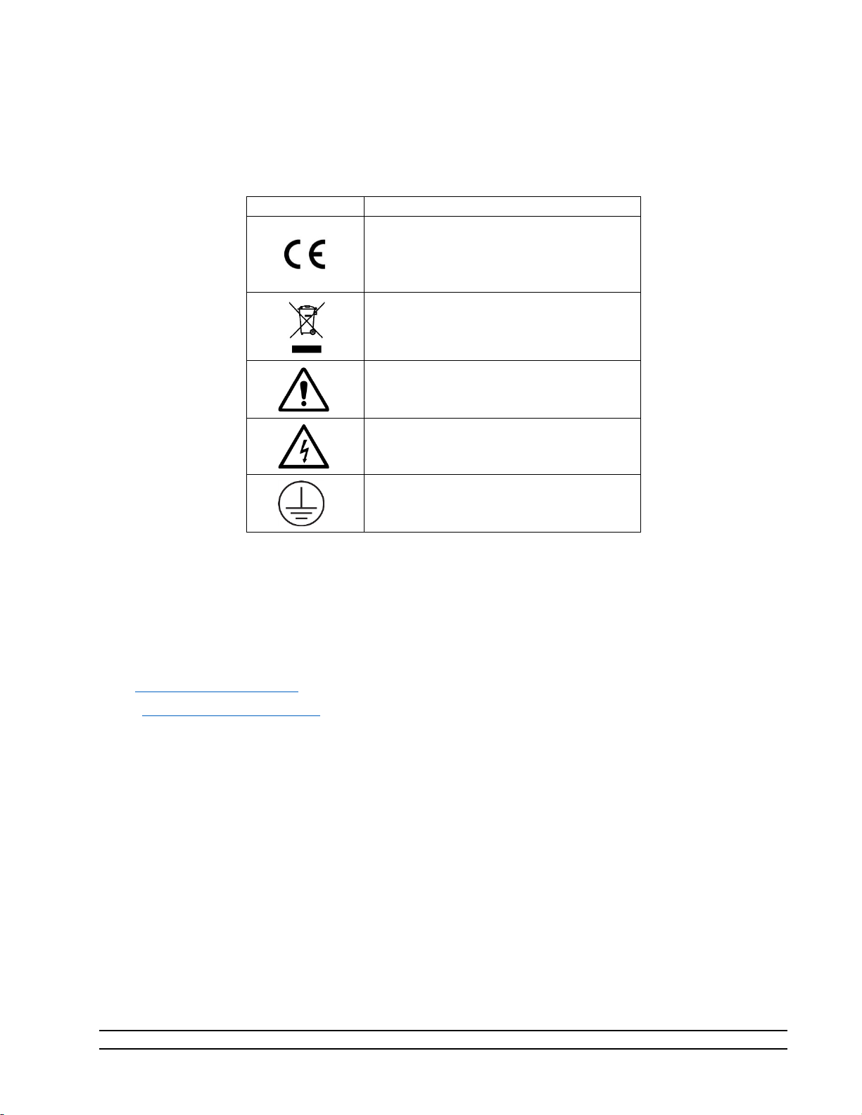
Safety terminology used for identification of any safety conditions are as follows:
Symbol
Description
The equipment has this symbol displayed
directives.
This symbol is shown from the WEEE
This symbol means Caution should be
This symbol indicates a potential shock
This symbol means Earth Ground.
Warning indicates a potential hazard may exist and the user should be extremely careful.
Caution! identifies a condition or action that may cause damage to the system or the user.
and indicates that the equipment meets
the requirements of the European safety
directive and indicates do not dispose of
this product in any municipal waste area.
observed or important information.
hazard may exist.
Table 1-1
2.4 TECHNICAL SUPPORT
If the user requires assistance with any aspect of the 2900 Humidity Generating System or the ControLog
application, technical support can be obtained by contacting Thunder Scientific Corporation by any of the
following means:
Web: www.ThunderScientific.com
Email: support@thunderscientific.com
Tel : 1-505-265-8701
FAX : 1-505-266-6203
2.5 LICENSE AGREEMENT
THIS IS A LEGAL AGREEMENT BETWEEN YOU, THE END USER, AND THUNDER SCIENTIFIC
CORPORATION ("TSC"). THE ENCLOSED THUNDER SCIENTIFIC CORPORATION SOFTWARE PROGRAM
(THE "SOFTWARE ") IS LICENSED BY THUNDER SCIENTIFIC CORPORATION TO THE ORIGINAL
CUSTOMER AND ANY SUBSEQUENT TRANSFEREE OF THE PRODUCT FOR USE ONLY ON THE TERMS SET
FORTH HERE. PLEASE READ THIS LICENSE AGREEMENT. IF YOU DO NOT AGREE TO THESE TERMS,
RETURN THE FULL PRODUCT WITH PROOF OF PURCHASE WITHIN 30 DAYS FOR A FULL REFUND.
•GRANT OF LICENSE. TSC grants to you the right to use one copy of the enclosed SOFTWARE on a single terminal
connected to a single computer (i.e. single CPU) or to a network server. If you install the SOFTWARE on a network
s
erver, you must purchase a separate copy of the SOFTWARE for each computer terminal that will be used to operate the
SOFTWARE. If the anticipated number of users of the SOFTWARE will exceed the number of applicable Licenses, the
you
must have a reasonable mechanism in place to ensure that the number of persons using the SOFTWARE concurrentl
n
y
8
Model 2900 System Manual – Document #OM2900 - Edition 2.0 - June 2022

does not exceed the number of Licenses. If the SOFTWARE is permanently installed on the hard disk or other storage
device of a computer (other than a network server) and one person uses that computer more than 80% of the time, then
that person may also use the SOFTWARE on a portable or home computer.
• COPYRIGHT. The SOFTWARE is owned by TSC and is protected by United States copyright laws and international
treaty provisions. You may either (a) make two copies of the SOFTWARE solely for backup or archival purposes provided
that you reproduce all copyright and other proprietary notices that are on the original copy of the SOFTWARE provided
to you, or (b) transfer the SOFTWARE to a single hard disk provided you keep the original solely for backup or archival
purpose. You may not copy the written materials accompanying the SOFTWARE.
• OTHER RESTRICTIONS. You may not rent or lease the SOFTWARE, but you may transfer the SOFTWARE and
accompanying written materials on a permanent basis provided you retain no copies and the recipient agrees to the terms
of this Agreement. You may not reverse engineer, decompile, disassemble, or create derivative works from the
SOFTWARE.
SOFTWARE and written materials
• GOVERNMENT LICENSEE. If you are acquiring the SOFTWARE on behalf of any unit or agency of the United States
Government, the following provisions apply:
The Government acknowledges TSC's representation that the SOFTWARE and its documentation were developed at
private expense and no part of them is in the public domain.
The Government acknowledges TSC's representation that the SOFTWARE is "Restricted Computer Software" as that term
is defined in Clause 52.227-19 of the Federal Acquisition Regulations (FAR) and is "Commercial Computer Software" as
that term is defined in Subpart 227.471 of the Department of Defense Federal Acquisition Regulations Supplement
(DFARS).
The Government agrees that:
(i) If the SOFTWARE is supplied to the Department of Defense (DoD), the SOFTWARE is classified as
"Commercial Computer Software" and the Government is acquiring only "restricted rights" in the SOFTWARE
and its documentation as that term is defined in Clause 252.227-7013(c) (1) of the DFARS, and
(ii) If the SOFTWARE is supplied to any unit or agency of the United States Government other than DoD, the
Government's rights in the SOFTWARE and its documentation will be as defined in Clause 52.227-19 (c) (2) of
the FAR.
• RESTRICTED RIGHTS LEGEND. Use, duplication, or disclosure by the Government is subject to restrictions as set
forth in subparagraph (c) (1) (ii) of the Rights in Technical Data and Computer Software clause at DFARS 252.227-7013.
Thunder Scientific Corporation, 623 Wyoming SE, Albuquerque, NM 87123.
• EXPORT LAW ASSURANCES. You acknowledge and agree that the SOFTWARE is subject to restrictions and controls
imposed by the United States Export Administration Act (the "Act") and the regulations thereunder. You agree and certify
that neither the SOFTWARE nor any direct product thereof is being or will be acquired, shipped, transferred or re-exported,
directly or indirectly, into any country prohibited by the Act and the regulations thereunder or will be used for any purpose
prohibited by the same.
• GENERAL. This Agreement will be governed by the laws of the State of New Mexico, except for that body of law
dealing with conflicts of law.
Should you have any questions concerning this Agreement, or if you desire to contact TSC for any reason, please write:
Thunder Scientific Corporation, 623 Wyoming NE, Albuquerque, NM 87123
Model 2900 System Manual – Document #OM2900 - Edition 2.0 - June 2022
9

2.6 WARRANTY
MADE IN USA
Thunder Scientific Corporation (TSC) warrants, to the Buyer, the Product manufactured by TSC to be free
of defects in material and workmanship under normal use and service and to be free from inadequate
mechanical design when operated within the specified design limitations for a period of one year from date
of acceptance. TSC's obligation under this warranty shall be limited to the following: The Product is
returned to TSC with transportation charges prepaid and that TSC's examination reveals the Product to be
defective. TSC, at its option, shall either refund to the Buyer the purchase price of the product or repair or
replace at TSC's plant, any part or parts of the Product which is or are defective. This warranty shall not
apply to any Product which has been maintained, handled, stored, repaired or altered in any manner, or by
anyone other than an authorized TSC representative, so as to affect adversely such Product or which has
been subject to improper installation, misuse, negligence, accident or corrosion. THIS WARRANTY IS
EXCLUSIVE AND IN LIEU OF ANY WARRANTY OF MERCHANTABILITY, FITNESS FOR A
PARTICULAR PURPOSE OR ANY OTHER WARRANTY, WHETHER EXPRESS OR IMPLIED,
AND ALL OTHER LIABILITIES AND OBLIGATIONS ON THE PART OF TSC; TSC SHALL NOT
BE LIABLE FOR ANY OTHER CLAIMS OR DAMAGES, EITHER DIRECT OR CONSEQUENTIAL,
ARISING DIRECTLY OR INDIRECTLY OUT OF SUPPLYING THE PRODUCT. All warranties,
express or implied, with respect to any device or component not manufactured by TSC but incorporated
into its Product are the responsibility of the original manufacturer and shall not affect or apply to TSC.
2.7 COPYRIGHT
©2009-2022 Thunder Scientific Corporation
623 Wyoming Blvd. SE
Albuquerque, New Mexico 87123, USA
This document contains proprietary information which is protected by copyright. All rights are reserved. No
part of this document may be reproduced or transmitted in any form or by any means, electronic or
mechanical, including photocopying and recording, for any purpose without the prior written consent of
Thunder Scientific Corporation.
2.8 TRADEMARKS
ControLog is a trademark of Thunder Scientific Corporation.
HumiCalc is a trademark of Thunder Scientific Corporation.
THUNDER SCIENTIFIC is the registered trademark of Thunder Scientific Corporation
Microsoft Software License Terms Last updated July 2017
Follow this link to view Microsoft’s Software License Terms or scan this QR code to download your copy.
https://www.microsoft.com/enus/Useterms/OEM/Windows/10/UseTerms_OEM_Windows_10_English.htm
icrosoft Corporation 2022 - https://www.microsoft.com/en-us/
M
10
Model 2900 System Manual – Document #OM2900 - Edition 2.0 - June 2022

2.9 SPECIFICATIONS
Relative Humidity Range: ............................................................................ 10 to 95 %RH, 10 to 40 L/min
1
Relative Humidity Range:
Frost Point Temperature Range: ........................................................................................... -33.60 to 0 °C
Dew Point Temperature Range: ......................................................................................... -36.94 to 70 °C
Chamber Fluid Temperature Range:
Chamber Fluid Temperature Control Stability:
Chamber Temperature Uniformity:
Chamber Fluid Temperature Heating Rate: from -10 to 72 °C ....................... 0.5 °C per Minute (average)
Chamber Fluid Temperature Cooling Rate: from 72 to 0 °C ........................... 0.5 °C per Minute (average)
Chamber Fluid Temperature Cooling Rate: from 0 to -10 °C .......................... 0.2 °C per Minute (average)
Temperature Specification: ........................................................................................................... 0.027 °C
Gas Type: ............................................................................................................................. Air or Nitrogen
Gas Pressure Rating: (MAWP) ....................................................................................................... 175 psiG
Gas Flow Rate Range: ........................................................................................................... 10 to 50 L/min
Gas Flow Rate Specification: ................................................................................................ 5% of full scale
Saturation Pressure Range: ......................................................................................... Ambient to 160 psiA
Saturation Pressure Specification: ................................................................................. 0.02% of full scale
Test Chamber Pressure Range: ..................................................................................... Ambient to 17 psiA
Test Chamber Pressure Specification: .............................................................................. 0.02% of reading
Supply Pressure Range: ............................................................................................... Ambient to 150 psiG
Supply Pressure Specification: ......................................................................................................... ±1 psiG
Display Resolution: .............................................................................................................................. 0.001
Test Chamber Dimensions: ......................................... 12” x 12” x 10” (304.8 mm x 304.8 mm x 254 mm)
Physical Dimensions: ....................................... 22” H x 36” W x 23” D (558.8 mm x 432 mm x 584.2 mm)
.......................................................................... 95 to 98 %RH, 10 to 20 L/min
2
..................................................................................... -10 to 72 °C
3
........................................................................... 0.002 °C
4
............................................................................................. < 0.04 °C
1
The system will limit mass flow rate to 20 L/min for %RH greater than 95.
2
Only the glycol/water heat transfer fluid circulating around the chamber is controlled to setpoint via the saturation
temperature probe. Chamber temperature inside the chamber may vary depending on door configuration, setup, and
uniformity. Note: the 2900 can only operate for a finite amount of time at or below 0 °C.
3
Temperature Control Stability is defined as the standard deviation over a 10-minute period, as measured by the
saturation temperature control sensor after being at point for 60 minutes.
4
Chamber Temperature Uniformity is defined as the maximum temperature difference between any two locations at a
single point in time. Locations are within one inch of the chamber wall and within 2.5 inches of the chamber door.
Using a minimum chamber fan speed of 25% for a temperature range of -10 °C to 72 ° when using fluid jacket door
option and ±10 °C from ambient when not.
Model 2900 System Manual – Document #OM2900 - Edition 2.0 - June 2022
11

2.10 UNCERTAINTY 5
RH Uncertainty: 10 to 95 %RH, 0 to 70 °C, 10 to 40 L/min ................................................. 0.5% of reading
RH Uncertainty: 95 to 98 %RH, 0 to 70 °C, 10 to 20 L/min ................................................. 0.5% of reading
Dew/Frost Point Uncertainty: < 0 °C, 10 to 40 L/min ...................................................................... 0.05 °C
Dew Point Uncertainty: 0 to 70 °C, 10 to 40 L/min .......................................................................... 0.08 °C
Temperature Uncertainty: -10 to 72 °C ......................................................................................... 0.031 °C
5
Chamber pressure at 1 atmosphere, Uncertainty values represent an expanded uncertainty using a coverage factor,
k=2, at an approximate level of confidence of 95%. Uncertainty is not specified at saturation temperatures below 0 °C
or at flow rates below 10 L/min. Uncertainty is based on the worst-case value from the 2900 uncertainty analysis.
12
Model 2900 System Manual – Document #OM2900 - Edition 2.0 - June 2022

2.11 FACILITY REQUIREMENTS
2.11.1 Environment
Operating Temperature: .......................................................................................................... 15 to 30 °C
Storage Temperature: ................................................................................................................ 0 to 50 °C
Humidity: ..................................................................................................... 5 to 95% RH Non-condensing
2.11.2 Floor Space
A bench and/or floor, capable of supporting approximately 300 pounds, with a minimum space of 27"
(0.686m) deep x 43" (1.09m) wide.
Allow an additional 20" (0.508m) in width for clearance, if possible, to allow complete opening of the
chamber door and access to the test ports.
Refer to drawings: 18D29901-2, 18D29910-1
2.11.3 Power
Electrical Power: ....................................................................... 200-230/210-240 V~, 10 A, 1 Ø, 50/60 Hz
Gas Supply Maximum Inlet Pressure: ...................................................................... 175 psiG @ 50 L/min
2.11.4 Air Supply
When not using the pneumatic cart, a clean, oil free instrument air supply operating at a @ 165 psiG and 50
L/m is required. The air supply should be filtered to a particle size of 0.5 microns or less, a hydrocarbon
content of 1 PPM or less, with a pressure dewpoint of 15 °C or less. Regulated supply pressure other than
recommended (175 psiG maximum) is acceptable but may limit the lowest humidity obtainable from the
generator and will require an internal pressure regulator (REG) adjustment.
Refer to section 2.12.5 Setting Supply Pressure Regulator for more information on adjusting the internal
pressure regulator (REG).
2.11.5 Distilled Water Supply
One gallon (3.8 liters) of double distilled water per fill. The one-gallon supply can last from 8 hours to more
than 500 hours of use depending upon the temperature and humidity at which the generator is operated
(reference section 13.3.4
for approximately 200 hours.
). During operation near ambient temperature and 50% RH, one gallon should last
Model 2900 System Manual – Document #OM2900 - Edition 2.0 - June 2022
13

2.12 INSTALLATION
2.12.1 Uncrating
Before uncrating, carefully inspect the crate and skid to be certain the unit was not subjected to damage. If
there is damage, proceed no further and notify your inspection department and the shipping agent.
If the crate appears satisfactory:
1. Remove steel strapping.
2. Using "Clip Removal Tool" or thin pry-bar, remove top cover clips then remove top panel.
3. One panel at a time, remove the panel clips then remove panel.
4. Remove polyethylene covering from unit.
5. Inspect for any visible damage.
6. Remove any/all accessory boxes.
7. Using forklift or another suitable lifting device, lift unit from skid and place on the 2900 cart or
instrument bench.
CAUTION!
BEFORE APPROACHING THE EQUIPMENT WITH THE FORKLIFT,
VISUALLY LOCATE ANY HARDWARE WHICH MIGHT PROJECT INTO
THE PATH OF THE FORKS. PLACE FORKS AS WIDE AS POSSIBLE TO
AVOID DAMAGE TO THE FRAME.
8. The unit may now be rolled to its point of installation.
2.12.2 Positioning
Position the system to have access to all sides of the console. Remove cover panels and inspect for any
visible damage that might have occurred during shipment.
CAUTION!
ALWAYS USE THE FILE>TURN OFF COMMAND TO PROPERLY EXIT THE SOFTWARE AND SHUTDOWN
THE COMPUTERS SO THAT THE MAIN POWER SWITCH CAN BE SWITCHED OFF.
2.12.3 Chamber Fluid
Temperature conditioning of the Model 2900 test chamber utilizes a mixture of propylene glycol and water
as a heat transfer fluid. This fluid is circulated by a magnetically coupled centrifugal pump through the
refrigeration and heating system and the fluid shell surrounding the test chamber.
2.12.3.1 Chamber Fluid Filling Procedure
1. Ensure main power switch is OFF.
2. Remove top console panel.
3. Locate fluid fill port (under insulation and labeled "Fluid Fill Port").
4. Remove "Red" cap and insert funnel into fluid fill port.
5. Add 2 gallons of 70% propylene glycol. Fill with water until level is approximately 1" (25.4 mm)
below the bottom of the fill port or until level touches funnel nozzle tip.
14
Model 2900 System Manual – Document #OM2900 - Edition 2.0 - June 2022

6. Remove funnel and replace fluid fill port cap and insulation.
7. Replace top console panel.
Refer to drawings: 18D29901-1, 18D29901-4, 18D29909-1
2.12.3.2 Chamber Fluid Draining Procedure
1. Ensure main power switch is OFF.
2. Remove rear console panel.
3. Locate drain hose in the lower left rear corner of the generator (when looking at the back of the
generator). It is the black hose with the yellow tip and brass cap.
4. Extend hose, remove drain hose cap and empty the chamber fluid into a clean container with a
minimum size of 4 gallons. Save the chamber fluid for refilling.
5. To restore hose: grasp hose and rotate counterclockwise ½ turn while pushing hose into left side
storage cavity.
6. Replace rear console panel
Refer to drawings: 18D29901-1, 18D29901-3, 18D29909-2
Model 2900 System Manual – Document #OM2900 - Edition 2.0 - June 2022
15

2.12.4 Reservoir Initial Filling Procedure
The reservoir requires an initial filling prior to first use, then periodic filling thereafter.
Refer to section 5.1 Water Reservoir Level
for detailed instruction on how to fill the reservoir.
2.12.5 Setting Supply Pressure Regulator
The supply pressure must be regulated to assure proper control and operation. The goal of the regulation is
to remove the spikes that occur during air supply generation.
– It is always recommended to double regulate the air supply; once at the supply and again at
Note
the 2900.
Adjust the 2900’s internal pressure regulator (REG) to 10 psiG below the supply pressure, but never above
150 psiG. For example, if the supply pressure indicates 165 psiG then adjust the internal pressure regulator
to 150 psiG. If the supply pressure indicates 155 psiG then adjust the internal pressure regulator to 145 psiG
(10 psiG below). For the best results operate the generator in run mode at the default flow rate to assure
the regulator adjustment corrects for any pressure drop caused by the flow rate.
1. Open the Supply Pressure Dialog by selecting “Supply Pressure” from the Utilities Menu Tab
2. Using a #6 or #8 straight blade screwdriver, rotate stem clockwise to increase pressure and
counterclockwise to decrease pressure while monitoring the supply pressure dialog window.
Refer to drawings: 18D29901-1, 18D29901-3, 18D29901-8
16
Model 2900 System Manual – Document #OM2900 - Edition 2.0 - June 2022

2.13 QUICK START
This section will provide the user a quick start on operating the generator. For detailed information on
operating the generator please refer to section 4 ControLog Interface
.
CAUTION!
DO NOT OPERATE THE GENERATOR WITHOUT CHAMBER FLUID.
2.13.1 Power-Up
To Power-Up the generator perform the following steps:
• Verify that the air supply connection has been made.
o If using the Series ACS2520 Air Compressor System (ACS)
The On/Off valve is open (handle inline).
The AC power cable is connected to the ACS box.
The remote air compressor control cable is connected from ACS box to generator.
The Remote/Manual switch on the left side of the ACS box is in the Remote position.
Toggle the power switch located on the left side of the ACS box to ON.
6
verify the following:
Note
– When the Remote/Manual switch is in the Remote position the ACS compressor will not run
when first switched to ON. The compressor is remotely controlled by the 2900 and will not start until
the user requests an operation that requires supply pressure.
o If using another air source, verify the following:
Supply is on and properly regulated.
• Verify that AC power cable is connected to the generator.
• Toggle the power switch located at the lower right rear of generator to ON. The generator will begin
to boot up.
6
Refer to Thunder Scientific’s website www.thunderscientific.com for the ACS2520 manual and more information on
the ACS2520.
Model 2900 System Manual – Document #OM2900 - Edition 2.0 - June 2022
17

2.13.2 Loading Screen
After the system boots the generator will show a loading screen which will indicate the status of the loading
process and will also show the software version of the generator.
18
Model 2900 System Manual – Document #OM2900 - Edition 2.0 - June 2022
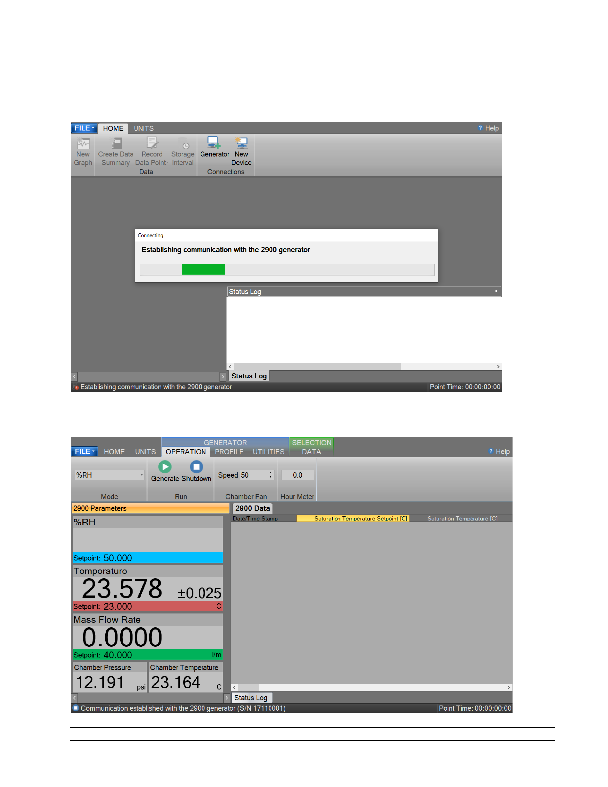
2.13.3 ControLog Screen
Upon completion of the loading process the generator will show the main ControLog page and a dialog
showing the status of establishing communication with the generator.
Once communication with the generator is established the generator’s parameter and data tabs will be
displayed.
Model 2900 System Manual – Document #OM2900 - Edition 2.0 - June 2022
19
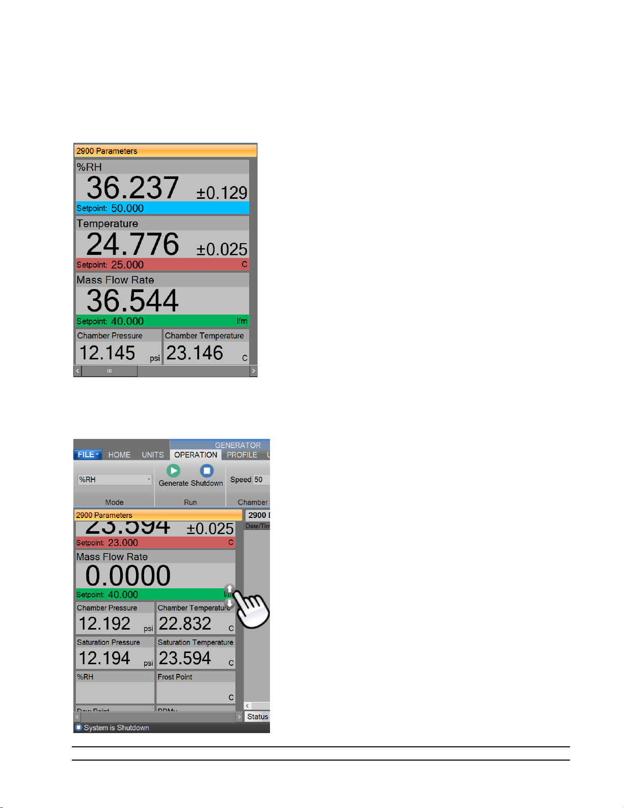
2.13.4 Control Parameters
The Parameter Tab Group is located on the left side of the application and contains a parameter tab for each
connected device. The 2900 Parameters contain all the control and measurement parameters critical to the
operation of
the humidity generator.
Scrolling the Parameters
Each Parameter Tab can be scrolled up and down to show additional parameters.
20
Model 2900 System Manual – Document #OM2900 - Edition 2.0 - June 2022

2.13.4.1 Setpoint Tile
The Setpoint Tiles allow the user to control the operation of the humidity generator by changing the desired
setpoint that the generator will control to. The Tiles contain 5 key parts; a header with the Parameter
Name, the Actual Value, the real-time Uncertainty Value, the Setpoint Value and the Unit the values are
displayed in. Each setpoint tile has a colored bar to allow quick indication of the what the tile is displaying
and in turn what the system is controlling. Blue is for the humidity that is being generated, red is for the
temperature that the system is controlling to and green is for the flow rate the system is generating at.
2.13.4.1.1 Changing Setpoints
To change a setpoint, click on the setpoint tile that you would like to change. A setpoint entry box will
appear. For example, to change the Percent Relative Humidity setpoint click on the %RH setpoint tile.
Enter the new value into the Setpoint Entry box and select Ok. Notice that the Percent Relative Humidity
setpoint value updates to the new value and the actual values begin moving toward the new setpoint.
Model 2900 System Manual – Document #OM2900 - Edition 2.0 - June 2022
21
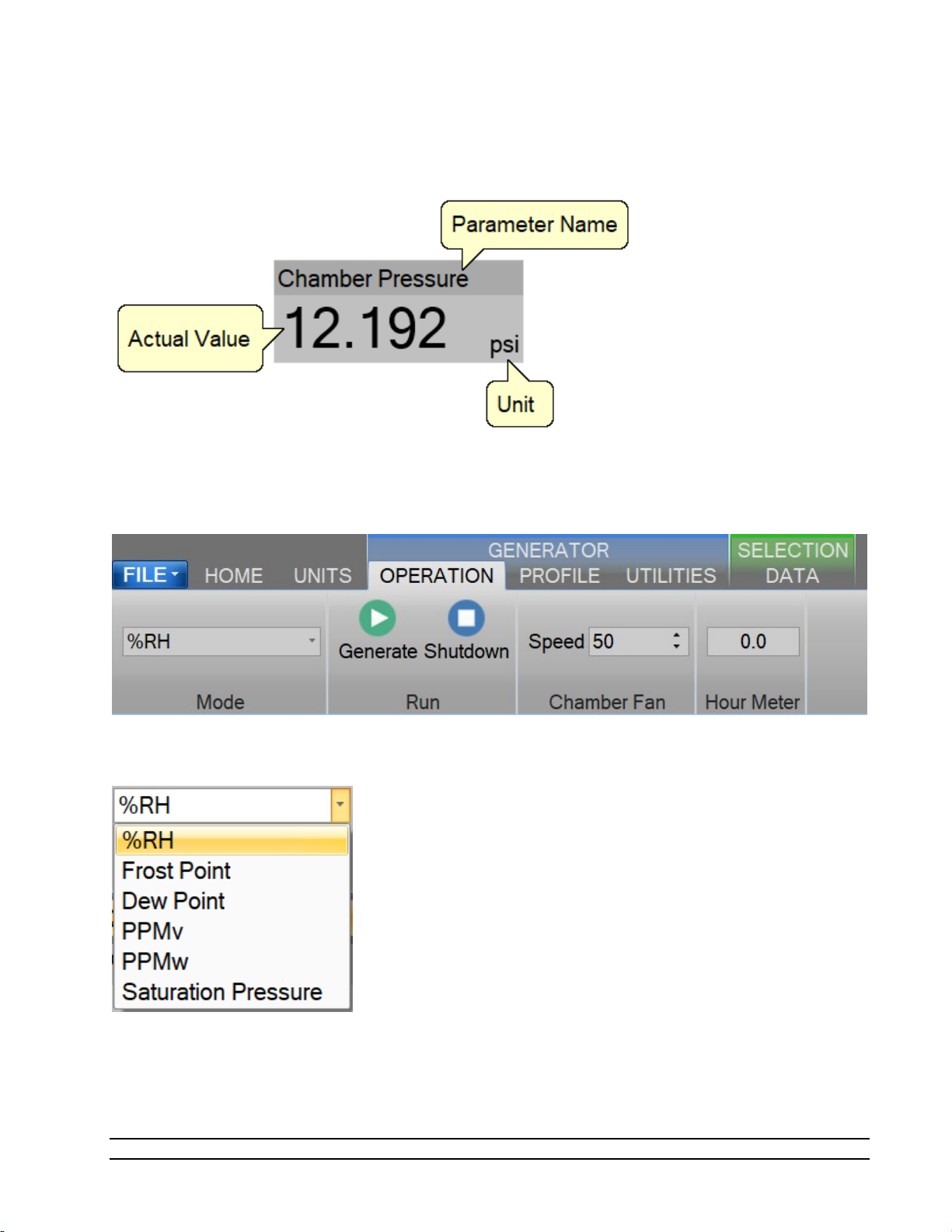
2.13.4.2 Value Tile
The Value Tiles display an actual value of a given parameter to the user. The Tiles contain 3 key parts; a
header with the Parameter Name, the Actual Value and the Unit the value is displayed in.
2.13.5 Control Modes
The user can change the operating mode of the 2900 by selecting from the drop-down menu within the
Mode group on the Generator’s Operation menu tab.
The drop-down allows the user to select between %RH, Frost Point, Dew Point, PPMv, PPMw, and Saturation
Pressure.
22
Model 2900 System Manual – Document #OM2900 - Edition 2.0 - June 2022
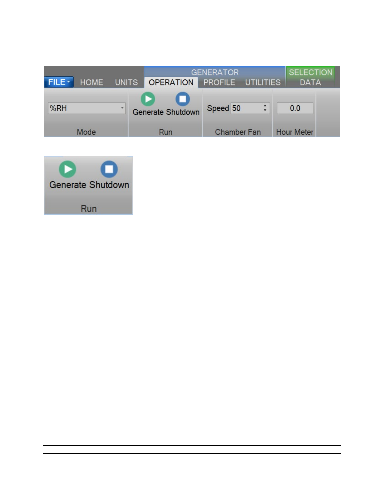
2.13.6 Generating and Shutting down
The Run Menu allows the user to run the 2900 manually.
The user can select to Generate or Shutdown.
2.13.6.1 Generate Mode
Selecting Generate from the run menu commands the 2900 into generate mode. When in the Generate
mode of operation, the system will control at the currently entered setpoints. Anytime a setpoint is
changed, the system immediately begins adjusting to that new value, and will control at the new point. The
Generate mode also allows you to change the humidity control mode at any time. For instance, the system
may be controlling %RH, then you may immediately switch to Dew Point control mode.
2.13.6.2 Shutdown
Selecting Shutdown from the run menu commands the 2900 to shutdown. The 2900 may be shutdown
whenever it is generating. When stopped, all system functions shutdown, pressure is vented, and the idle
Control/Display screen is shown. During this idle time, when the 2900 is stopped, gas is not flowing through
the generator.
Model 2900 System Manual – Document #OM2900 - Edition 2.0 - June 2022
23
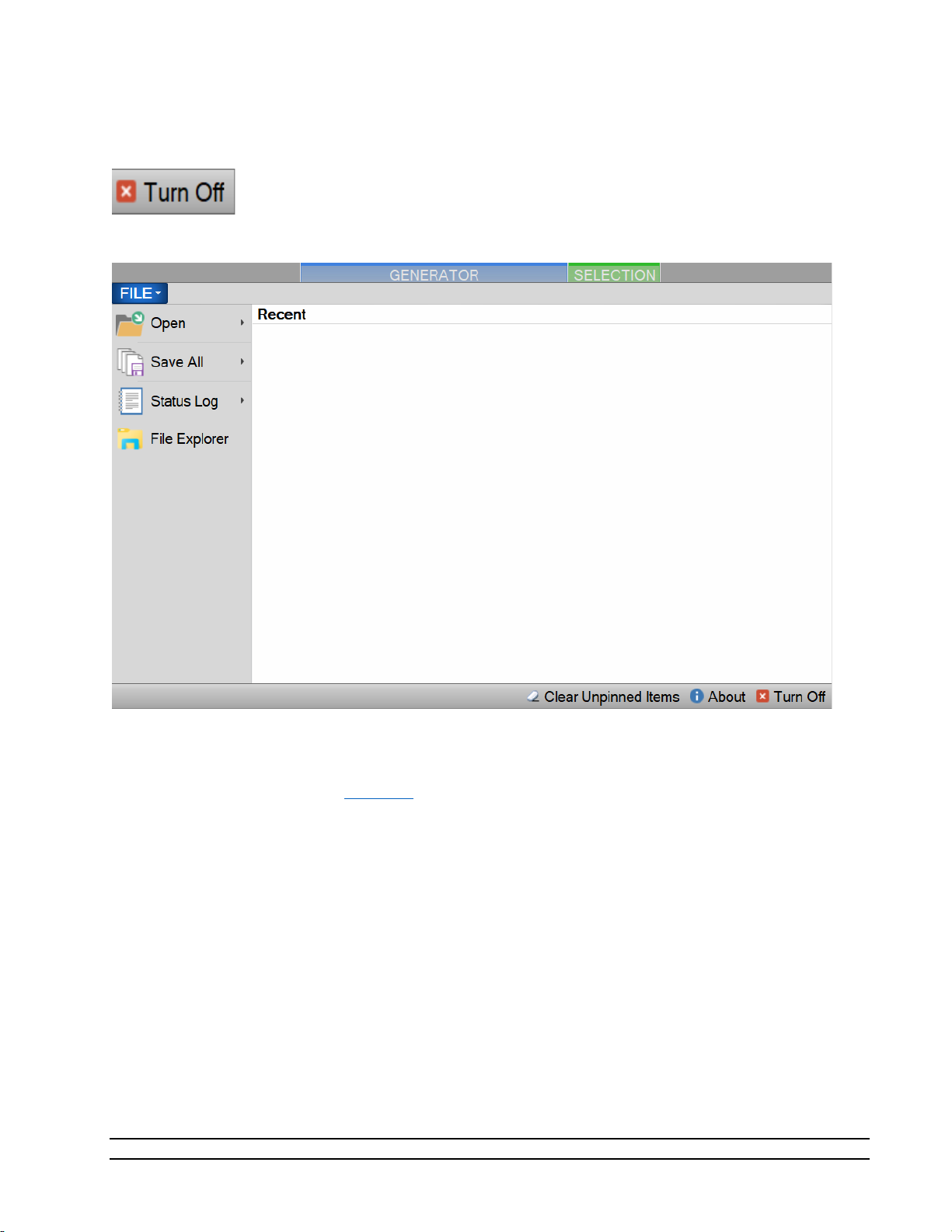
2.13.7 Power-Off
To turn the system off select the “Turn Off” command.
The “Turn Off” command is located under the “File” menu.
The Turn Off command will properly exit the software and shutdown the computers so that the main power
switch can be switched off.
– Always perform a Shutdown from the Operation Menu Tab before turning off the System.
Note
If there is current data that has yet to be saved the user will be asked to save the data before the system
shuts down. Selecting this command when the generator is generating will result in the automatic
shutdown of the generator.
The user is safe to switch the power switch to OFF once the PC has shut down completely (display goes
blank).
CAUTION!
TURNING OFF POWER WITHOUT SHUTTING DOWN THE SYSTEM
FIRST CAN CORRUPT THE EMBEDDED WINDOW SYSTEM DRIVE.
24
Model 2900 System Manual – Document #OM2900 - Edition 2.0 - June 2022

2.13.8 Set Date and Time
The user can change the current system date and time through the status bar context menu.
– To avoid time stamp confusion only change the system date and time when the generator is
Note
shutdown and not recording data.
Start by long pressing or right clicking anywhere within the status bar. A long press is when you touch and
hold the screen.
Long enough for a square selection box to appear.
Releasing will open the status bar context menu.
Model 2900 System Manual – Document #OM2900 - Edition 2.0 - June 2022
25

Select “Set Date and Time” from the context menu to open the system Date and Time dialog.
2.13.9 Help
The Help Menu located on the upper right side of the screen, allows the user to open the 2900 System
Manual.
Note – Refer to the Thunder Scientific website (www.thunderscientific.com
) for the latest manual
edition and other information on your Model 2900 Humidity System.
26
Model 2900 System Manual – Document #OM2900 - Edition 2.0 - June 2022

3 PRINCIPLE OF OPERATION
The Model 2900 humidity generation system is based on the two-pressure principle. This process (shown
below in elemental schematic form) involves saturating air or nitrogen, with water vapor at a given
temperature and pressure. The saturated high-pressure gas flows through an expansion valve where it is
isothermally reduced to test pressure. The indications of saturation temperature, saturation pressure,
chamber temperature, and chamber pressure are then used in the determination of all hygrometric
parameters such as %RH, Dew Point, PPM, etc. Humidity generation by this system does not depend upon
measuring the amount of water vapor, but rather is dependent on the measurements of temperature and
pressure alone. The precision of the system is determined by the accuracy of the temperature and pressure
measurements, and on the constancy of them throughout.
3.1 PRE-SATURATION (T
The air stream of a two-pressure generator must be 100% saturated with water vapor at saturation
temperature on the high-pressure (saturator) side of the expansion valve. This is accomplished by first
passing the air stream through a "Pre-Saturator". The Pre-Saturator is a vertical pressure vessel presenting a
water surface to the incoming air stream and is maintained at a temperature warmer than saturation
temperature conditions. The Pre-Saturator temperature probe is used in the control of the Pre-Saturator
heaters, which when activated, are used to control this temperature offset.
3.2 EXPANSION VALVE (T
The expansion valve temperature probe is used in the control of the expansion valve heater, which when
activated, is used to warm the expansion valve body, offsetting the cooling effects due to gas expansion.
This expansion valve temperature is always maintained above the saturation temperature.
Model 2900 System Manual – Document #OM2900 - Edition 2.0 - June 2022
PSAT
EXV
)
)
27

3.3 SATURATION TEMPERATURE (TS)
The saturation temperature probe is used to measure the fluid temperature at which the airstream is fully
saturated with water vapor. This is a fundamental measurement for a Two-Pressure humidity generator.
Saturation temperature is controlled directly through the Temperature setpoint.
Refer to section 2.9 Specifications
Note - The 2900 can only operate for a finite amount of time at or below 0 °
for range.
3.4 CHAMBER TEMPERATURE (TC)
The chamber temperature probe is used to measure the temperature within the test chamber. This is a
fundamental measurement for a Two-Pressure humidity generator. Chamber temperature is controlled
indirectly through the temperature setpoint.
Refer to section 2.9 Specifications
for range.
3.5 SATURATION PRESSURE (PS)
The Saturation Pressure transducer measures and controls the absolute pressure at which airstream is fully
saturated with water vapor at saturation temperature conditions. This is a fundamental measurement for a
Two-Pressure humidity generator. Saturation pressure can be controlled directly using the Saturation
Pressure setpoint or indirectly through the humidity mode setpoint.
Refer to section 2.9 Specifications
for range.
3.6 CHAMBER PRESSURE (PC)
The chamber pressure transducer is used to measure the pressure within the test chamber. This is a
fundamental measurement for a Two-Pressure humidity generator. Chamber pressure is ambient pressure
and is not controlled.
Refer to section 2.9 Specifications
for range.
3.7 HUMIDITY FORMULAS
The humidity (or water vapor content) of a gas may be expressed in a variety of ways. While some basic
understanding of humidity is helpful, thorough knowledge of the formulas and their relationships to the
2900 is not a requirement for successful operation of the generator. Refer to the HumiCalc with Uncertainty
Reference Manual for a full description of the equations used by the 2900 to generate a known humidity
and corresponding uncertainty value.
28
Model 2900 System Manual – Document #OM2900 - Edition 2.0 - June 2022

4 CONTROLOG INTERFACE
This section will provide the user with a detailed overview of ControLog’s layout and design. It is intended to
allow the user to gain familiarity with ControLog’s user interface. The sections following will provide a deeper
operational view of the functionality that ControLog offers.
The ControLog application is composed of five basic features: Ribbon Style Menu Bar, Parameter Tab Group,
Data and Graph Tab Group, Information Tab Group and the Status Bar. Each feature is designed to be intuitive
to use and to provide the user with detailed information on the operation of the generator and/or connected
device(s).
Model 2900 System Manual – Document #OM2900 - Edition 2.0 - June 2022
29

4.1 MENU BAR
The Ribbon Style Menu Bar is located at the top of the application and contains various selectable menu
groups, which provide access to the different ControLog functions and controls. The Generator group
provides commands that are directly related to the operation of the generator such as Operation, Profile,
and Utilities. The Selection group is dynamic and provides commands based on the Data and Graph Tab
Group tab that is currently selected. For example, if a data tab is selected, commands related to data will be
available. If a graph tab is selected, then commands related to the graph will be available.
4.1.1 File Menu Tab
The File Menu allows the user to perform file specific commands to open previous data files, profiles and
device configurations. It also allows the user to save all open data or graphs, clear the status log, save the
status log, restore the tab layout, about the application and shutdown system.
30
Model 2900 System Manual – Document #OM2900 - Edition 2.0 - June 2022

4.1.1.1 Open Data File
The Open file menu command allows the user to open previous data files for further review and analysis,
device configurations for device data logging and profiles for generator automation.
Selecting one of these commands will open a file dialog that will allow the user to browse to the desired
location for the file to open.
ControLog can open data saved in the follow type and format:
• Text File (Comma Delimited) (*.csv;*.txt)
• Text File (Tab Delimited) (*.dat;*.txt)
• Excel Workbook (*.xlsx;*.xls)
• Backup ControLog File (*.backup)
The user can also view and select to open recent files and has the option to “Pin” the file for quicker access
later on. This can be very useful if you have a device configuration that is often used or a commonly used
profile as it removes the process of navigating and selecting the file each time.
Model 2900 System Manual – Document #OM2900 - Edition 2.0 - June 2022
31

4.1.1.2 Save All Data
The Save All file menu command allows the user to save all current open data tabs to individual files using a
common name. This feature allows the user to quickly save multiple data tabs in a single operation.
Selecting this command will open a save file dialog that will allow the user to specify the name and browse
to the desired location to save the file.
ControLog can save data in the following type and format:
• Comma-Separated Values (*.csv)
• Text File (Comma Delimited) (*.txt)
• Text File (Tab Delimited) (*.txt)
• Excel Workbook (*.xlsx)
• Excel 97-2003 Workbook (*.xls)
Example: If the user had two data tabs open, one called “2900 Data” and the other called “Agilent 34970A
Data” and the user wanted to save the files as Excel Workbooks using the name “Test Data 10Dec15”.
ControLog would save two files to the user specified location with the follow names:
• Test Data 15Oct17 (2900).xls
• Test Data 15Oct17 (Agilent 34970A).xls
32
Model 2900 System Manual – Document #OM2900 - Edition 2.0 - June 2022

4.1.1.3 Status Log
The Status Log file menu command allows the user to Clear or Save the status log.
The Clear command allows the user to clear all current entries in the status log. The user will be asked to save
the status log data before the log is cleared.
The Save command allows the user to save the current entries in the status log. Selecting this command will
open a save file dialog that will allow the user to specify the name and browse to the desired location to save
the file. All status log files are saved in HTML format (*.html).
4.1.1.4 File Explorer
Opens a Windows file explore to allow the user to manage files. This can be used to easily copy data and
report files from the 2900 to an extern USB drive.
4.1.1.5 Clea r Unpinned Items
Clears all unpinned items in the list of recent files.
Model 2900 System Manual – Document #OM2900 - Edition 2.0 - June 2022
33

4.1.1.6 About ControLog
The About ControLog help menu command opens a dialog giving information on the ControLog application
including software version numbers and build dates.
4.1.1.7 Turn Off
The Turn Off command allows the user to properly exit the software and shutdown the computers so that
the main power switch can be switched off. If there is current data that has yet to be saved the user will be
asked to save the data before the system shuts down. Selecting this command when the generator is
generating will result in the automatic shutdown of the generator.
Note
– Always perform a Shutdown from the Operation Menu Tab before commanding a Shutdown
System.
The user is safe to switch the power switch to OFF once the PC has shut down completely (display goes
blank).
CAUTION!
TURNING OFF POWER WITHOUT SHUTTING DOWN THE SYSTEM
FIRST CAN CORRUPT THE EMBEDDED OPERATING SYSTEM.
4.1.2 Home Menu Tab
The home menu tab allows the user to create new graphs and data summaries, record data points, connect
to the generator and create new device connections. It also allows the user to change ControLog’s displayed
units. The Temperature, Pressure, Flow Rate, Density and Enthalpy units can be changed.
4.1.2.1 New Graph
The New graph menu command allows the user to create a new graph. Selecting this command will open a
New Graph Wizard dialog that will step the user through the selection process of what data the user would
like to include in the new graph. This operation is always available.
34
Model 2900 System Manual – Document #OM2900 - Edition 2.0 - June 2022
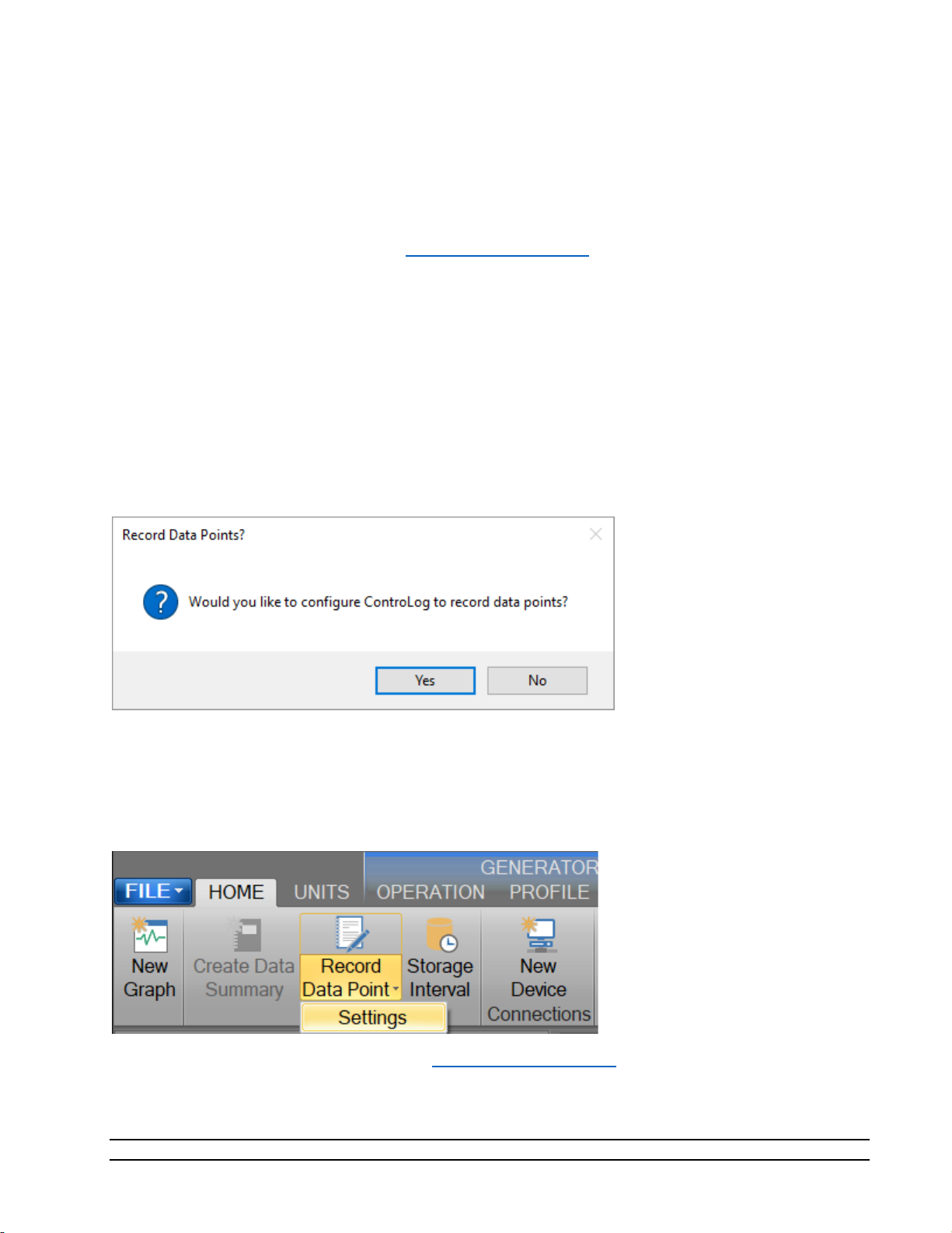
4.1.2.2 Create Data Summary
The Create Data Summary data command allows the user to create a summary of any currently opened
data. The feature lets the user specify what items, from which device, and at what intervals to include in the
data summary. The data summary can also calculate error between the specified standard and the device
under test. This operation is available whenever there is an open Data tab that contains data.
For more information, refer to section 8 Data and Data Summary
4.1.2.3 Record Data Point
The Record Data Point data command allows the user to record certain data items from any currently
connected device either manually, with each manual device entry or at the completion of each soak phase in
an auto profile. The user can specify the number of prior data points to include and has the option to
automatically calculate average and or standard deviation of the prior data points. There are two submenus
for this menu command; Settings and Take Point. This operation is available whenever device or generator
data is being logged. The user can manually take a point using the button or by using the keyboard shortcut
“Ctrl-P”.
If the user has not configured the system to record data points, then ControLog will ask the user if they would
like to define the settings before taking a point.
4.1.2.3.1 Settings
The Settings submenu allows the user to define which data items and from which connected device they
would like to record when a point is taken. They can also define the number of points prior to include and
whether to calculate average and or standard deviation. The user can also configure when to take points,
either manually, at the end of a profile soak phase or when a manual device entry is taken.
For more information, refer to section 8 Data and Data Summary
Model 2900 System Manual – Document #OM2900 - Edition 2.0 - June 2022
35
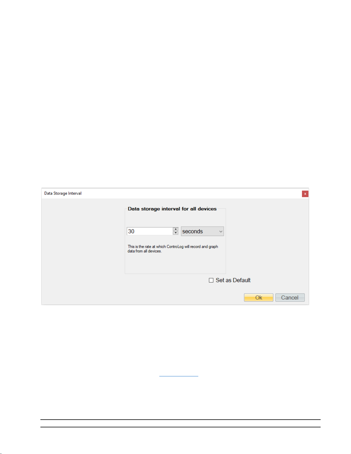
4.1.2.4 Data Storage Interval
The Data Storage Interval data command allows the user to change the storage interval that data is
recorded. This is the rate at which data is recorded to the data tabs for all connected devices. Selecting this
command will open the “Data Storage Interval” dialog that will allow the user to change the data storage
interval during the generate operation. If the “Set as Default” is checked, the new value will become the
default start up interval. If not checked, the new value will only affect the current session.
IMPORTANT!
STORING AND MAINTAINING DATA CAN BECOME A TIME-CONSUMING
PROCESS. THE MORE DATA THAT IS STORED IN THE DATA TAB, THE
SLOWER AND LESS RESPONSIVE THE COMPUTER MAY SEEM. FOR THIS
REASON, SOME CONSIDERATION SHOULD BE GIVEN TO THE AMOUNT OF
DATA DESIRED, THE OVERALL TIME SPAN OF THE DATA (I.E. HOURS,
POSSIBLY DAYS), AND ULTIMATELY THE DATA INTERVAL.
Note - Data is only recorded while the 2900 is in generate mode.
4.1.2.5 New Device
The New Device connection command allows the user to create a new device connection. Selecting this
command will open a Connection Wizard dialog that will step the user through the process of creating a new
connection to a device.
For more information, refer to section 10 Connections
36
Model 2900 System Manual – Document #OM2900 - Edition 2.0 - June 2022

4.1.3 Units Menu Tab
The Units Menu Tab allows the user to change ControLog’s displayed units. The Temperature, Pressure,
Flow Rate, Density and Enthalpy units can be changed.
- All parameter tabs and graph tabs will be updated with the selected unit, but the data tabs will
Note
not change. All data tab values remain in SI units which provide a consistent unit base for saved data.
4.1.3.1.1 Temperature Unit
The Temperature Unit allows the user to change the displayed units for temperatures.
Available temperature units:
• °F
• °C
• K
4.1.3.1.2 Pressure Unit
The Pressure Unit allows the user to change the displayed units for pressure.
Available pressure units:
• psi
• atm
• Pa
• hPa
• kPa
• MPa
• bar
• millibar
Model 2900 System Manual – Document #OM2900 - Edition 2.0 - June 2022
37

4.1.3.1.3 Flow Unit
The Flow Unit allows the user to change the displayed units for flow.
Available flow units:
• l/m
• l/h
• cfm
• cfh
4.1.3.1.4 Density Unit
The Density Unit allows the user to change the displayed units for density.
Available density units:
• g/L
• g/m^3
• lb/ft^3
4.1.3.1.5 Enthalpy Unit
The Enthalpy Unit allows the user to change the displayed units for enthalpy.
Available enthalpy units:
• btu/lb
• J/g
4.1.4 Operation Menu Tab
The Operation Menu Tab gives the user the ability to control the operation of the generator, from what
humidity operating mode to the startup and shutdown of the generator.
38
Model 2900 System Manual – Document #OM2900 - Edition 2.0 - June 2022

4.1.4.1 Mode
The Mode Menu allows the user to change the operating mode of the 2900. It allows the user to select
between %RH, Frost Point, Dew Point, PPMv, PPMw, and Saturation Pressure.
4.1.4.1.1 %RH Control Mode
The %RH Control Mode, %RH, is controlled at a constant value by varying saturation pressure, Ps, to
compensate for any changes in saturation temperature, Ts, chamber temperature, Tc, or chamber pressure,
Pc. While %RH is held constant, all other humidity parameters may vary.
4.1.4.1.2 Frost Point Control Mode
The Frost Point Control Mode, Tf, is controlled at a constant value by varying the saturation pressure, Ps, to
compensate for changes in either saturation temperature, Ts, or chamber pressure, Pc. While Frost Point is
held constant other humidity parameters may vary. Frost Point is independent of chamber temperature.
4.1.4.1.3 Dew Point Control Mode
The Dew Point Control Mode, Td, is controlled at a constant value by varying saturation pressure, Ps, to
compensate for any changes in either saturation temperature, Ts, or chamber pressure, Pc. While Dew Point
is held constant, other humidity parameters may vary. Dew Point control mode is valid both above and
below 0 °C, and Dew Point is independent of chamber temperature.
4.1.4.1.4 PPMv Control Mode
The PPMv Control Mode is controlled at a constant value by varying saturation pressure, Ps, to compensate
for any changes in saturation temperature, Ts. While PPMv is held constant, other humidity parameters may
vary. PPMv is independent of chamber pressure and chamber temperature.
4.1.4.1.5 PPMw Control Mode
The PPMw Control Mode is controlled at a constant value by varying saturation pressure, Ps, to compensate
for any changes in saturation temperature, Ts. While PPMw is held constant, other humidity parameters
may vary. PPMw is independent of chamber pressure and chamber temperature.
4.1.4.1.6 Saturation Pressure Control Mode
The Saturation Pressure Control Mode, Ps, is controlled at a constant value independent of any other
pressure, temperature, or humidity value. While saturation pressure is held constant, all humidity
parameters may vary.
Model 2900 System Manual – Document #OM2900 - Edition 2.0 - June 2022
39
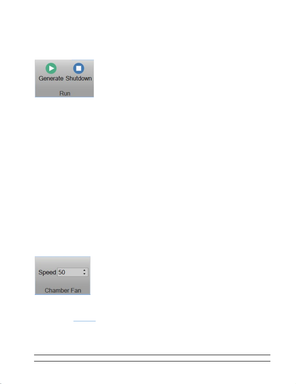
4.1.4.2 Run Menu
The Run Menu allows the user to run the 2900 manually in generate mode. The Run menu also allows the
user to manually shutdown the 2900.
4.1.4.2.1 Generate Mode
Selecting Generate from the run menu commands the 2900 into generate mode. Generate mode is used to
operate the system when exact humidity points or associated time intervals have not been determined,
when data must be viewed and/or verified manually before proceeding to the next humidity point, or when
more immediate control over the generated humidity is required. When in the Generate mode of
operation, the system will control at the currently entered setpoint indefinitely. Anytime a setpoint is
changed, the system immediately begins adjusting to that new value, and will control at the new point
indefinitely. Generate mode offers the flexibility to change the setpoint at any time and does not force you
into any set sequence or for any prescribed amount of time. The Generate mode also allows you to change
the humidity control mode at any time. For instance, the system may be controlling Frost Point, then you
may immediately switch to PPMv control mode.
4.1.4.2.2 Shutdown
Selecting Shutdown from the run menu commands the 2900 to shutdown. The 2900 may be shutdown
while generating. When stopped, all system functions shutdown, pressure is vented, and the idle
Control/Display screen is shown. During this idle time, when the 2900 is stopped, gas is not flowing through
the saturator.
4.1.4.3 Chamber Fan Menu
The Chamber Fan Menu allows the user to control the 2900 chamber fan speed. The chamber fan speed can
be controlled from 0 (off) to 100 (max speed). The user can specify a speed by entering a value directly or
by using the up/down arrows to increment the speed by 10.
Note – The chamber fan will only operate when the system is generating.
Refer to drawing: 18D29908
40
Model 2900 System Manual – Document #OM2900 - Edition 2.0 - June 2022

4.1.4.4 Hour Meter
The Hour Meter allows the user to see the number of operational hours the generator has on it. The hour
meter indicates the number of hours the generator has been operated in the generate mode.
4.1.5 Profile Menu Tab
The Profile Menu Tab allows the user to manage Auto Profiles. Auto Profiles give the user the ability to
program a set of humidity and temperature test points and dwell times that will automate the 2900
generation process. The profile menu is dynamic and has operations that are specific to the profile tab.
Specific operations will be hidden when another non-profile tab is selected.
The Auto Profiling feature is very similar to the Generate mode with the main exception that profiling relies
on a predefined list of setpoints referred to as a profile. The user configurable profile is used as ControLog's
road map during Auto Profile operation. It defines which setpoint values to go to, at what rate to go from
one setpoint to another, and how long to stay at a specific setpoint before moving to the next one.
For more information, refer to section 9 Profiling
.
4.1.5.1 New Profile
The New profile command allows the user to create a new Auto Profile.
4.1.5.2 Save Profile
The Save profile command allows the user to save the currently opened Profile. Selecting this command will
open a save file dialog that will allow the user to specify the name and browse to the desired location to
save the file. ControLog Auto Profiles are saved in XML format with a *.profile extension.
4.1.5.3 Close Profile
The Close profile command allows the user to close the Profile tab. Selecting this command will close the
Profile tab, but if the profile has not been saved, ControLog will ask the user to save the profile before
closing the Profile tab.
Model 2900 System Manual – Document #OM2900 - Edition 2.0 - June 2022
41

4.1.5.4 Insert Point
The Insert Point command allows the user to insert new profile points between existing points. ControLog
will insert a new point at the selected location and will automatically predict the values.
4.1.5.5 Delete Point
The Delete Point command allows the user to delete the selected profile point.
4.1.5.6 Run Auto Profile
The Run Auto Profile command allows the user to start an Auto Profile. Selecting this command will open
the Profile Starting Point dialog which allows the user to select which point in the profile they would like to
start the profile on.
4.1.5.7 Hold Point
The Hold Point profile command allows the user to hold or pause the current Auto Profile point. Selecting
Hold Point pauses the current point, allowing the system to remain indefinitely at the current point. While in
a hold mode, the system is prevented from completing the ramp, assurance, or soak phases for a point. To
resume the profile point, select the menu item again. This re-enables the point and allows the profile to
resume normal operation.
4.1.5.8 Next Point
The Next Point profile command allows the user to skip to the next point in the Auto Profile. Selecting Next
Point manually advances to the next point, skipping any remaining ramp, assurance, or soak phase.
4.1.5.9 Next Phase
The Next Phase profile command allows the user to skip to the next phase in the Auto Profile. Selecting
Next Phase manually advances to the next phase. It causes Ramp Phase to proceed to the Assurance or Soak
Phase, Assurance to proceed to Soak, or Soak to proceed to Ramp of the next profile point. This allows for
early manual termination of any phase within a profile point.
42
Model 2900 System Manual – Document #OM2900 - Edition 2.0 - June 2022

4.1.6 Utilities Menu Tab
The Utilities Menu Tab gives the user access to various utilities functions such as Fluid Levels, Supply
Pressure, generator Calibration, System Parameters, Expanded Parameters, generator Uncertainty and
Access Control.
4.1.6.1 Reservoir Level
The Reservoir Level indicates the current level of the water reservoir and when pressed, opens up the 2900
fluid level interaction dialog that allows the user to view the state of the various fluid levels and liquid level
states.
For more information, refer to section 5 Fluid Levels
.
4.1.6.2 Supply Pressure
The Supply Pressure indicates the current supply pressure and when pressed opens a dialog box for the user
to view the current supply pressure (in gauge). If the generator is shutdown, this command will also open
the supply pressure solenoid (and start the airbox is equipped). The exact pressure value will vary based on
the air supply connected to the generator.
Model 2900 System Manual – Document #OM2900 - Edition 2.0 - June 2022
43

If the supply pressure is set too high a warning message will be displayed. The user will need to reduce the
pressure regulator until the message disappears.
Refer to section 2.12.5 Setting Supply Pressure Regulator
for detailed instruction on how to set the supply
pressure regulator.
4.1.6.3 Generator Calibration
The Generator Calibration command opens the Calibration Wizard dialog for calibration of the Model 2900
Humidity generator’s temperature probes, pressure transducers and mass flow meter. ControLog will
request a password to access the calibration functionality since it will affect the accuracy and possibly the
operation of the generator if incorrectly performed. The passwords are located on the yellow product key
flyer delivered with the generator.
For more information, refer to section 6 Calibration
44
Model 2900 System Manual – Document #OM2900 - Edition 2.0 - June 2022

4.1.6.4 System Parameters
The System Parameter command opens the System Parameter Wizard dialog to allow adjustment of the
generator’s system parameters that pertain to operation, control, limits and etc. The User tab is accessible
with User Access Level and lets the user change things like power up setpoints, supply gas dryness and
HumiCalc parameters such as molecular weight of the supply gas.
All the other tabs require Admin Access Level and changes should only be made upon request by Thunder
Scientific Technical Support.
4.1.6.5 Expanded Para meters
The Expanded Parameters command opens a second tab in the Parameter Tab Group with additional
generator parameters used for technical support. This tab does not need to be opened during normal
operation but can be used to help diagnose problems when requesting technical support. This tab will
automatically be displayed when operating the generator under the “Admin” access level.
4.1.6.6 Import Uncertainty Solution (Requires Manager Access Level or above)
The Import Uncertainty Solution file command allows a manager to import a HumiCalc with Uncertainty
solution into ControLog to define the uncertainty for the Model 2900 humidity generator. Selecting this
command will open an “Import Uncertainty” dialog that will step the user through the import process. Refer
to your HumiCalc with Uncertainty Reference Manual for more information on creating uncertainty
solutions.
Model 2900 System Manual – Document #OM2900 - Edition 2.0 - June 2022
45
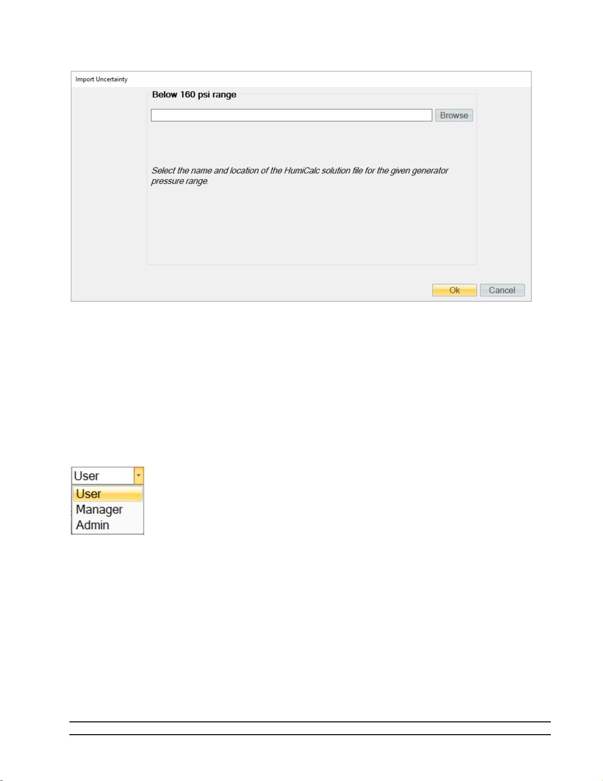
Clicking the “Browse” button will open a file dialog that will allow the user to browse to the desired location
for the solution file to open. Once a file has been selected, clicking the “Ok” button will complete the import
process and may display a status dialog as the solution is imported into ControLog.
4.1.6.7 HumiCalc with Uncertainty
The HumiCalc with Uncertainty command opens the standalone HumiCalc with Uncertainty application. It is
recommended to use the USB keyboard when working with the HumiCalc with Uncertainty application.
4.1.6.8 Access Control
The Access Control Menu allows the user to change the access level. The user can select between User,
Manager, and Admin
4.1.6.8.1 User Access Level
The User Access Level is default level and allows the user to run the generator, calibrate the generator, but
does not give access to change system parameters, edit calibration coefficients or open interface console.
No password is required for this level
4.1.6.8.2 Manager Access Level
The Manager Access Level is one level above the user level and allows the user to run the generator,
calibrate the generator, edit calibration coefficients but does not give access to change system parameters
or open interface console. A password is required for this level.
46
Model 2900 System Manual – Document #OM2900 - Edition 2.0 - June 2022

4.1.6.8.3 Admin Access Level
The Admin Access Level gives the user full access to run the generator, calibrate the generator, edit
calibration coefficients, change system parameters and open interface console. This level is intended for
factory support and should not be used regularly by the user of the 2900. A password is required for this
level.
4.1.7 Graph Menu Tab
The Graph Menu Tab allows the user to create a New graph, Save, Close, Zoom, Scale, Auto Scale and set the
Properties for the selected graph. The graph menu tab is part of the selection group which changes based
on what data, graph or parameter tab is selected. The Graph Menu Tab will only operate on the currently
selected graph tab.
For more information, refer to section 7 Graphing.
4.1.7.1 New Graph
The New graph command allows the user to create a new graph. Selecting this command will open a New
Graph Wizard dialog that will step the user through the selection process of what data the user would like to
include in the new graph. This operation is always available.
4.1.7.2 Save Graph
The Save graph command allows the user to save the selected graph. Selecting this command will open a
save file dialog that will allow the user to specify the name and browse to the desired location to save the
file. ControLog graphs can be saved in following graphic file types:
• Bitmap (*.bmp)
• Graphics Interchange Format (*.gif)
• Joint Photographic Experts Group (*.jpg)
• W3C Portable Network Graphics (*.png)
• EMF Enhanced Metafile Format (*.emf)
4.1.7.3 Close Graph
The Close graph command allows the user to close the selected graph. Selection will result in a confirmation
message to assure the user wants to close the graph.
Model 2900 System Manual – Document #OM2900 - Edition 2.0 - June 2022
47

4.1.7.4 Zoom Graph
The Zoom graph command allows the user to zoom a rectangular area of the graph. Selecting this command
allows the user to create a rectangular area on the graph that will be zoomed.
4.1.7.4.1 Zoom Graph’s X Axis
The Zoom X Axis graph command allows the user to zoom along the X Axis of the graph. Selecting this
command allows the user to create a sectioned area on the graph that will be zoomed along the X Axis.
4.1.7.4.2 Zoom Graph’s Y Axis
The Zoom Y Axis graph command allows the user to zoom along the Y Axis of the graph. Selecting this
command allows the user to create a sectioned area on the graph that will be zoomed along the Y Axis.
4.1.7.5 Scale Graph
The Scale graph command allows the user to scale both the X and Y axis. Selecting this command allows the
user to use the scale using a touch or mouse gesture. Dragging the cursor up, scales the display in (zooms
in) and dragging the cursor down, scales the display out (zoom out).
48
Model 2900 System Manual – Document #OM2900 - Edition 2.0 - June 2022

4.1.7.5.1 Scale Graph X-Axis
The Scale X-Axis graph command allows the user to scale the X axis. Selecting this command allows the user
to use the scale using a touch or mouse gesture. Dragging the cursor up scales the X-Axis in (zooms X-Axis
in) and dragging the cursor down scales the X Axis out (zooms X-Axis out).
4.1.7.5.2 Scale Graph Y-Axis
The Scale Y-Axis graph command allows the user to scale the Y axis. Selecting this command allows the user
to use the scale using a touch or mouse gesture. Dragging the cursor up scales the Y-Axis in (zooms Y-Axis
in) and dragging the cursor down scales the Y Axis out (zooms Y-Axis out).
4.1.7.6 Auto Scale
The Auto Scale graph command allows the user to reset the graph view to encompass all data. Selecting this
command will automatically reset both axis of the graph so that the entire data set of each item is contained
within the boundaries of the graph.
4.1.7.7 Graph Properties
The Graph Properties graph menu command allows the user to modify the properties of the selected graph.
Selecting this command opens the Graph Properties dialog that allows the user to make changes to what
data is graphed, the display properties for each line and the axis values.
4.1.8 Data Menu Tab
The Data Menu Tab allows the user to Save, Clear, Close, Select, Copy, Create and change the Storage
Interval. The data menu tab is part of the selection group which changes based on what data, graph or
parameter tab is selected. The Data Menu Tab will only operate on the currently selected data tab.
For more information, refer to section 8 Data and Data Summary
Model 2900 System Manual – Document #OM2900 - Edition 2.0 - June 2022
49

4.1.8.1 Save Data
The Save data command allows the user to save the selected data tab. Selecting this command will open a
save file dialog that will allow the user to specify the name and browse to the desired location to save the
file. ControLog can save data in the following type and format:
• Comma-Separated Values (*.csv)
• Text File (Comma Delimited) (*.txt)
• Text File (Tab Delimited) (*.txt)
• Excel Workbook (*.xlsx)
• Excel 97-2003 Workbook (*.xls)
4.1.8.2 Clear Data
The Clear data command allows the user to clear the selected data tab. ControLog will ask the user to save
any unsaved data tab before the tab is cleared. This operation is available only when at least one data point
has been recorded in the selected data tab.
4.1.8.3 Close Data
The Close data command allows the user to close the selected data tab. ControLog will ask the user to
confirm before closing the tab and any unsaved data tab will also prompt the user to save the data before
the tab is closed. This operation is available only when the device for the selected data tab is disconnected.
4.1.8.4 Select All Data
The Select All data command allows the user to select all the data within a data tab.
4.1.8.5 Copy Selection
The Copy Selection command allows the user to copy the selected data within a data tab to the clipboard.
Selecting this command will copy the selected data within a data tab to the clipboard in a tab delimited
format. This data may then be pasted into another program.
4.1.8.6 Create Data Summary
The Create Data Summary data command allows the user to create a summary of any currently opened
data. The feature lets the user specify what items from which device and at what intervals to include in the
data summary. The data summary can also calculate error between the specified standard and the device
under test. This operation is available whenever there is an open Data tab that contains data.
For more information, refer to section 8 Data and Data Summary
4.1.8.7 Record Data Point
The Record Data Point data command is the same as the one on the Home tab. It allows the user to record
certain data items from any currently connected device either manually, with each manual device entry or
at the completion of each soak phase in an auto profile. The user can specify the number of prior data points
to include and has the option to automatically calculate average and or standard deviation of the prior data
points. There are two submenus for this menu command; Settings and Take Point. This operation is
available whenever device or generator data is being logged. The user can manually take a point using the
button or by using the keyboard shortcut “Ctrl-P”.
50
Model 2900 System Manual – Document #OM2900 - Edition 2.0 - June 2022

If the user has not configured the system to record data points, then ControLog will ask the user if they would
like to define the settings before taking a point.
4.1.8.7.1 Settings
The Settings submenu allows the user to define which data items and from which connected device they
would like to record when a point is taken. They can also define the number of points prior to include and
whether to calculate average and or standard deviation. The user can also configure when to take points,
either manually, at the end of a profile soak phase or when a manual device entry is taken.
For more information, refer to section 8 Data and Data Summary
4.1.8.8 Data Storage Interval
The Data Storage Interval data command allows the user to change the storage interval that data is
recorded. This is the rate at which data is recorded to the data tabs for all connected devices. Selecting this
command will open the “Data Storage Interval” dialog that will allow the user to change the data storage
interval during the generate operation. If the “Set as Default” is checked, the new value will become the
default start up interval. If not checked, the new value will only affect the current session.
IMPORTANT!
STORING AND MAINTAINING DATA CAN BECOME A TIME-CONSUMING
PROCESS. THE MORE DATA THAT IS STORED IN THE DATA TAB, THE
SLOWER AND LESS RESPONSIVE THE COMPUTER MAY SEEM. FOR THIS
REASON, SOME CONSIDERATION SHOULD BE GIVEN TO THE AMOUNT OF
DATA DESIRED, THE OVERALL TIME SPAN OF THE DATA (I.E. HOURS, DAYS,
POSSIBLY WEEKS), AND ULTIMATELY THE DATA INTERVAL.
Model 2900 System Manual – Document #OM2900 - Edition 2.0 - June 2022
51
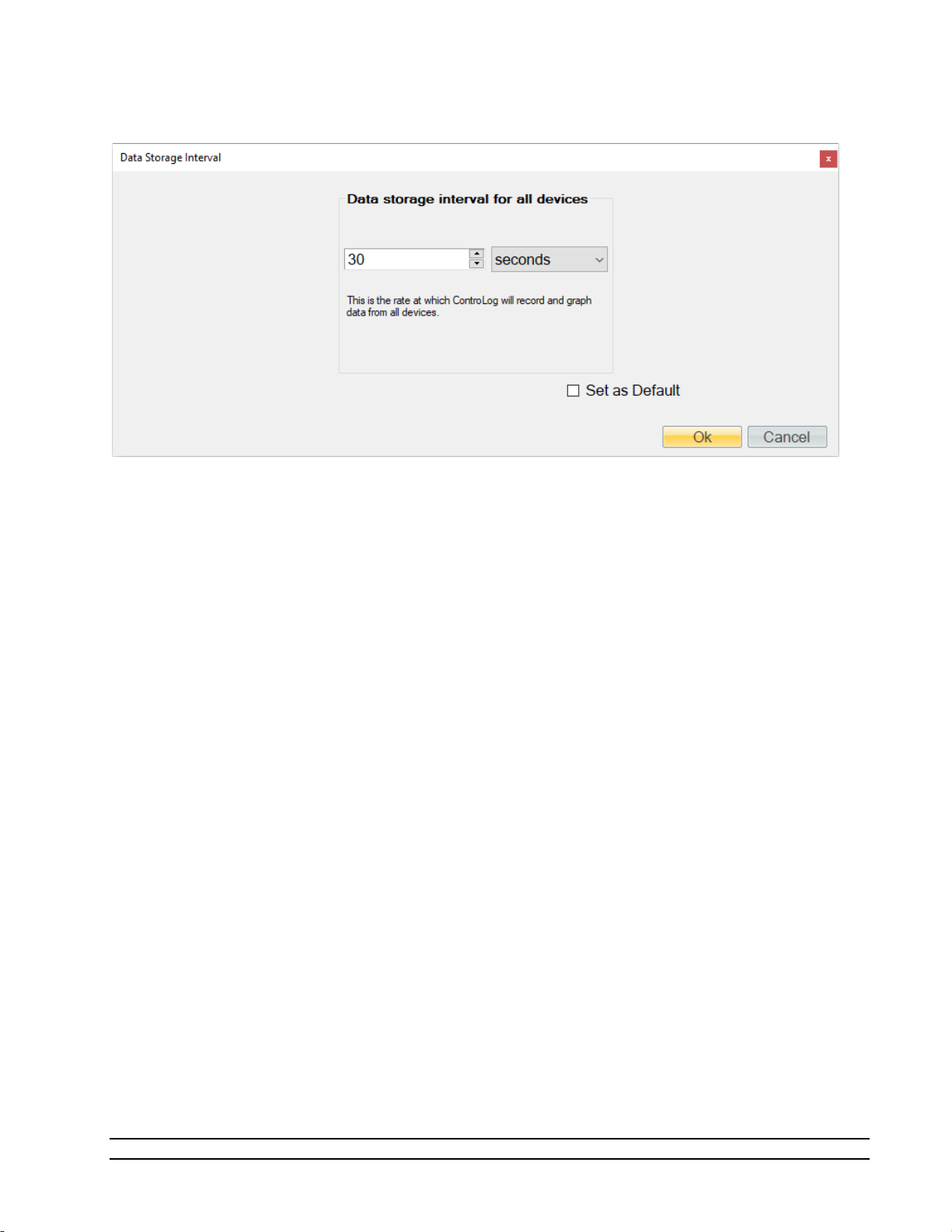
Note - Data is only recorded while the 2900 is in generate mode. Data is also stored at the generate
rate whenever a device is connected and the 2900 is not connected. This gives the user the ability to
use ControLog as a logging application for any device they can connect without the need of a Model
2900 Humidity generator.
52
Model 2900 System Manual – Document #OM2900 - Edition 2.0 - June 2022

4.1.9 Device Settings Menu Tab
The Settings Menu Tab allows the user to change the settings of a device connection, disconnect a device
connection and open an interface console to view communication with a device.
4.1.9.1 New Device
The New Device connection command allows the user to create a new device connection. Selecting this
command will open a Connection Wizard dialog that will step the user through the process of creating a new
connection to a device.
For more information, refer to section 10 Connections
4.1.9.2 Settings
The Settings connection menu command allows the user to change the settings for a specific connection.
Selecting this command will open the Connection Wizard dialog for the selected connection, allowing the
user to change connection settings as desired.
Model 2900 System Manual – Document #OM2900 - Edition 2.0 - June 2022
53

4.1.9.3 Disconnect
The Close connection menu command allows the user to close a specific connection. ControLog will ask the
user to confirm before closing the connection.
4.1.9.4 Interface Console
The Open Device Interface Console connection menu command under Settings allows the user to open a
device console tab. The device console tab allows the user to view the commands being sent to and
received from any given connected device.
The user can select which connected device to view using the drop-down selection at the top of the tab.
The data sent to and received from the selected device is displayed in the lower text area of the console tab.
54
Model 2900 System Manual – Document #OM2900 - Edition 2.0 - June 2022

4.1.10 Help
The Help Menu located on the right side of the ribbon menu, allows the user to open the 2900 System
Manual (this document).
Note – Refer to the Thunder Scientific website (www.thunderscientific.com) for the latest manual
edition and other information on your Model 2900 Humidity System.
Model 2900 System Manual – Document #OM2900 - Edition 2.0 - June 2022
55
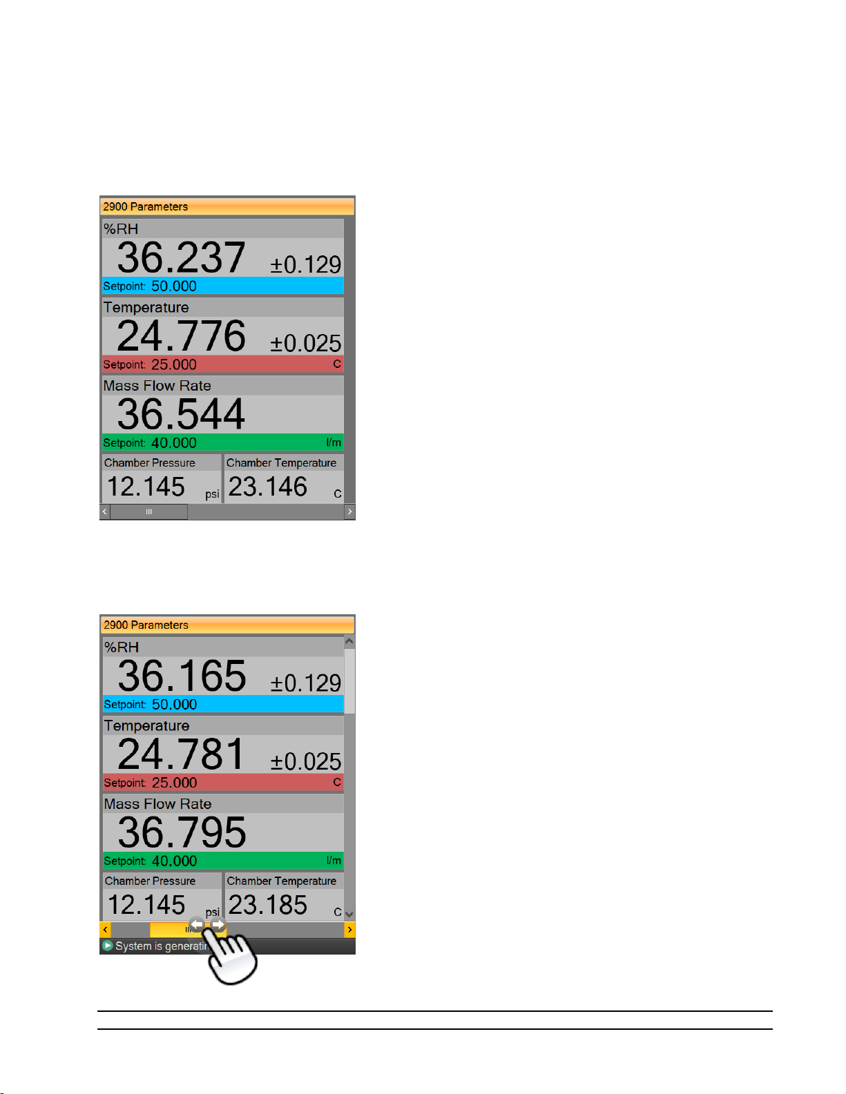
4.2 PARAMETERS TAB GROUP
The Parameter Tab Group is located on the left side of the application and contains a parameter tab for each
connected device. Each parameter tab displays the current data for its device and a parameter tab can be
selected using the scroll bar at the bottom of the group.
If multiple parameter tabs are open the user can accessed other tabs using the scroll bar at the bottom of
the group.
56
Model 2900 System Manual – Document #OM2900 - Edition 2.0 - June 2022

All Device Parameter Tabs have a context menu that can be displayed by long pressing the tab title area or
by right clicking in the tab area. The context menu allows quick access to the device related functions that
are available in the Settings Menu Tab.
Model 2900 System Manual – Document #OM2900 - Edition 2.0 - June 2022
57

4.2.1 Tiles
Within each parameter tab area are tiles that allow the user to set setpoints, view actual values, and view
real-time uncertainty values. There are two different tiles; a Setpoint Tile and a Value Tile.
58
Model 2900 System Manual – Document #OM2900 - Edition 2.0 - June 2022

4.2.1.1.1 Setpoint Tile
The Setpoint Tiles allow the user to control the operation of the humidity generator by changing the desired
setpoint that the generator will control to. The Tiles contain 5 key parts; a header with the Parameter
Name, the Actual Value, the real-time Uncertainty Value, the Setpoint Value and the Unit the values are
displayed in. Each setpoint tile has a colored bar to allow quick indication of the what the tile is displaying
and in turn what the system is controlling. Blue is for the humidity that is being generated, red is for the
temperature that the system is controlling to and green is for the flow rate the system is generating at.
4.2.1.1.1.1 Changing Setpoints
To change a setpoint, click on the setpoint tile that you would like to change. A setpoint entry box will
appear. For example, to change the Percent Relative Humidity setpoint click on the %RH setpoint tile.
Enter the new value into the Setpoint Entry box and select Ok. Notice that the Percent Relative Humidity
setpoint value updates to the new value and the actual values begin moving toward the new setpoint.
The user can also pop-up a mini version of HumiCalc to help calculate the desired setpoint by clicking the
drop-down arrow on the setpoint entry box.
For example, let’s say the user wants to calculate the lowest %RH achievable given a limited supply pressure
of only 100 psi.
Model 2900 System Manual – Document #OM2900 - Edition 2.0 - June 2022
59

Start by opening the HumiCalc pop-up using the drop-down arrow at the right of the setpoint entry box.
Next, select the known to be Saturation Pressure and enter the 100-psi supply pressure max.
60
Model 2900 System Manual – Document #OM2900 - Edition 2.0 - June 2022

Clicking the “Calculate” button will result in the calculated %RH based on the 100 psi limit being placed in
the Setpoint Entry Box and will close the HumiCalc pop-up.
Clicking “Ok” will close the setpoint entry and will send the setpoint to the Model 2900 Humidity generator.
4.2.1.1.2 Value Tile
The Value Tiles display an actual value of a given parameter to the user. The Tiles contain 3 key parts; a
header with the Parameter Name, the Actual Value and the Unit the value is displayed in.
Model 2900 System Manual – Document #OM2900 - Edition 2.0 - June 2022
61

4.2.2 2900 Parameter Tab
The 2900 Parameters contain all the control and measurement parameters critical to the operation of the
humidity generator.
The 2900 Parameters can be scrolled up and down to show the currently generated humidity in different
humidity terms that are calculated using the HumiCalc with Uncertainty engine, along with other values that
are important to the operation of the 2900 generator.
62
Model 2900 System Manual – Document #OM2900 - Edition 2.0 - June 2022

4.2.2.1 Actively Controlled Humidity
The first tile on the Control Parameters is the actively controlled humidity parameter. For instance, if
ControLog were set to control the generator on dew point, then Dew Point would be listed as the first
parameter rather than %RH.
This setpoint controls the humidity being generated.
4.2.2.2 Saturation Pressure
The Saturation Pressure is the pressure reading of the saturator pressure transducer (T2).
For more information, refer to section 3 Principle of Operation
4.2.2.3 Chamber Pressure
Chamber Pressure is the pressure reading of the chamber pressure transducer (T3).
For more information, refer to section 3 Principle of Operation
4.2.2.4 Temperature
Temperature is the temperature reading of the saturator temperature probe (RTD1) which is a direct
indication of the fluid system temperature.
This setpoint controls the fluid system temperature within the system while generating.
4.2.2.5 Saturation Temperature
Saturation Temperature is the temperature reading of the saturator temperature probe (RTD1).
For more information, refer to section 3 Principle of Operation
Note - The 2900 can only operate for a finite amount of time at or below 0 °
4.2.2.6 Chamber Temperature
Chamber Temperature is the temperature reading of the chamber temperature probe (RTD4).
For more information, refer to section 3 Principle of Operation
4.2.2.7 Mass Flow Rate
Mass Flow Rate is the mass flow reading of the flow meter (T4). This is the actual flow of the air supply
entering the Pre-Saturator and is an indication of the total flow through the system once the saturation and
chamber pressure have stabilized.
The Mass Flow Rate setpoint controls the mass flow rate of the system.
4.2.2.8 %RH
Percent Relative Humidity (%RH) is the ratio of the amount of water vapor in a given sample to the
maximum amount possible at the same temperature and pressure. %RH is calculated at the chamber
pressure and chamber temperature relative to the saturation pressure and saturation temperature. This is
the most accurate calculation of %RH at the point in the immediate vicinity of the chamber temperature
probe. Placing the chamber temperature probe at the humidity sensing point of the devices under test gives
the actual value of the relative humidity being imposed on the devices, as it is dependent on both pressure
and temperature.
63
Model 2900 System Manual – Document #OM2900 - Edition 2.0 - June 2022

4.2.2.9 Frost Point
Frost Point Temperature is the temperature to which a gas must be cooled in order to just begin condensing
water vapor in the form of frost or ice, and therefore only exists at values below 0.01 °C. When operating
the system with indicated Frost Points above 0.01 °C, the values indicated are to be interpreted as Dew
Points. However, Frost Point is not the same as Dew Point for values below freezing. Frost Point is
independent of test chamber temperature.
4.2.2.10
Dew Point Temperature is the temperature to which a gas must be cooled in order to just begin condensing
water vapor in the form of dew. Generally, Dew Point exists at temperatures above freezing. In many
instances, Dew Point may actually exist at indicated values below freezing (super-cooled dew). However, it
is important to note that Dew Point is not the same as Frost Point. Dew Point is independent of test
chamber temperature.
Dew Point
4.2.2.11 PPMv
Parts per Million by Volume is a ratio of the number of molecules of water vapor to the number of
molecules of the other constituents in the gas. Once established, PPMv is pressure and temperature
insensitive, and is therefore independent of test chamber temperature and test chamber pressure.
4.2.2.12 PPMw
Parts per Million by Weight is a ratio of the weight of the water vapor in a sample to the weight of the
remaining constituents in the gas. Once established, PPMw is pressure and temperature insensitive, and is
therefore independent of test chamber temperature and test chamber pressure.
4.2.2.13 Grains/lb
Grains per pound is a ratio of the weight, in grains, of water vapor to the weight, in pounds, of the other
constituents in the gas. (7000 grains = 1 pound). Once established, Grains/lb is pressure and temperature
insensitive, and is therefore independent of test chamber temperature and test chamber pressure.
4.2.2.14 Enthalpy
Enthalpy is a measure of the amount of energy required to change a gas from one temperature/humidity
value to another. In application, enthalpy is not used as an absolute value, but rather it is the difference in
enthalpy between two distinct points which are of interest. The datum point which results in zero enthalpy
was therefore arbitrarily chosen at a test temperature of 0 °C and 0 %RH. Applying enthalpy is a matter of
computing the difference in enthalpy between two or more distinct data points.
4.2.2.15 SVP@Tt
Saturation Vapor Pressure (SVP) computed at the Test Temperature.
4.2.2.16 SVP@Td
Saturation Vapor Pressure (SVP) computed at the Dew/Frost Point Temperature.
4.2.2.17 SVP@Ts
Saturation Vapor Pressure (SVP) computed at the Saturation Temperature.
4.2.2.18 F@Tt.Pt
Enhancement Factor at Test Temperature and Pressure.
64
Model 2900 System Manual – Document #OM2900 - Edition 2.0 - June 2022

4.2.2.19 F@Td.Pt
Enhancement Factor at Dew/Frost Point Temperature and Test Pressure.
4.2.2.20 F@Ts.Ps
Enhancement Factor at Saturation Temperature and Pressure.
4.2.2.21 Specific Humidity
Specific Humidity is a ratio of the weight of the water vapor to the total weight of the humidified gas.
Specific Humidity is independent of test chamber temperature.
4.2.2.22 Absolute Humidity
Absolute Humidity is the weight of the water vapor per unit volume of humidified gas.
4.2.2.23 Dry Air Density
Dry Air Density is the partial density in weight per unit volume of only the dry air portion of a moist air
sample. In other words, if the water vapor were removed from a fixed volume of air, the remaining dry air
would exhibit this density.
4.2.2.24 Moist Air Density
Moist Air Density is the total weight per unit volume of a moist air sample. This density includes both the
weight of the air and the weight of the water vapor.
4.2.2.25 Wet Bulb Temperature
Wet Bulb temperature is used in wet bulb/dry bulb aspirated Psychrometry, and is the temperature
measured by a temperature probe whose tip is coated with water (typically by being covered with a wet
sock). When aspirated at a constant air velocity, the wet bulb will cool due to evaporation of the water from
the probe. The cool temperature, to which it equilibrates, is used in the calculation of humidity parameters.
4.2.2.26 Mixing Ratio by Volume
Mixing Ratio by Volume is a ratio of the partial pressure of the water vapor to the partial pressure of the
remaining constituents in the sample. Mixing Ratio by Volume is independent of test chamber temperature.
4.2.2.27 Mixing Ratio by Weight
Mixing Ratio by Weight is a ratio of the weight of the water vapor to the weight of the remaining
constituents in the sample. Mixing Ratio by Weight is independent of test chamber temperature.
4.2.2.28 Percent by Volume
Percent by Volume is a ratio (expressed as a percentage) of the partial pressure of the water vapor to the
total pressure of the sample. Percent by Volume is independent of test chamber temperature.
4.2.2.29 Percent by Weight
Percent by Weight is a ratio (expressed as a percentage) of the weight of the water vapor to the total weight
of the sample. Percent by Weight is independent of test chamber temperature.
4.2.2.30 Vapor Mole Fraction
Vapor Mole Fraction is the mole fraction of water vapor in a sample.
Model 2900 System Manual – Document #OM2900 - Edition 2.0 - June 2022
65

4.2.2.31 Dry Air Mole Fraction
Dry Air Mole Fraction is the mole fraction of the dry air portion of a sample. The dry air portion is
considered to be all constituents in a gas exclusive of the water vapor.
4.2.2.32 Cabinet Temperature
Cabinet Temperature is the temperature reading of the cabinet temperature probe (RTD5).
4.2.2.33 Exp-Valve Temperature
The Exp-Valve Temperature is the temperature reading of the expansion valve probe (RTD3)
For more information, refer to section 3 Principle of Operation
4.2.2.34 Pre-Saturator Temperature
The Pre-Saturator temperature is the temperature reading of the Pre-Saturator probe (RTD2).
For more information, refer to section 3 Principle of Operation
4.2.2.35 Supply Pressure
Supply pressure is the pressure reading of the gas supply pressure transducer (T1). The supply pressure value
is gauge pressure.
4.2.2.36 Water Reservoir Level
Water reservoir level (LL1, LL1P) is the liquid level reading of the water within the reservoir.
Refer to section 5.1.1 Fill Water Reservoir
for detailed instruction on how to fill the reservoir.
66
Model 2900 System Manual – Document #OM2900 - Edition 2.0 - June 2022
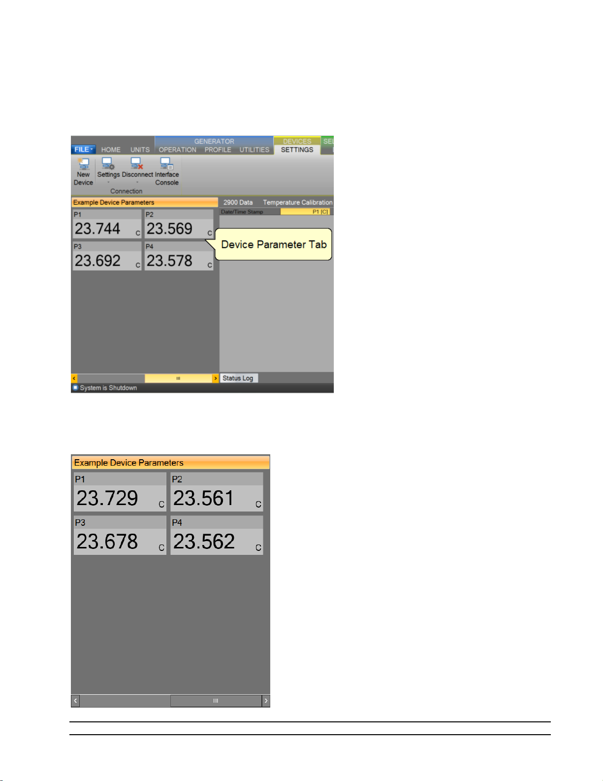
4.2.3 Device Parameter Tabs
The Device Parameter Tabs show the current actual values for the given device. The tabs are visible
whenever the device is connected. The Device Parameters will display a scrollbar as needed to allow for
varying display sizes without loss of data.
4.2.3.1 Device Parameters
Device Parameters contain all the most recent actual measurement parameters received from the device.
Each parameter is displayed in a separate Value Tile.
Model 2900 System Manual – Document #OM2900 - Edition 2.0 - June 2022
67
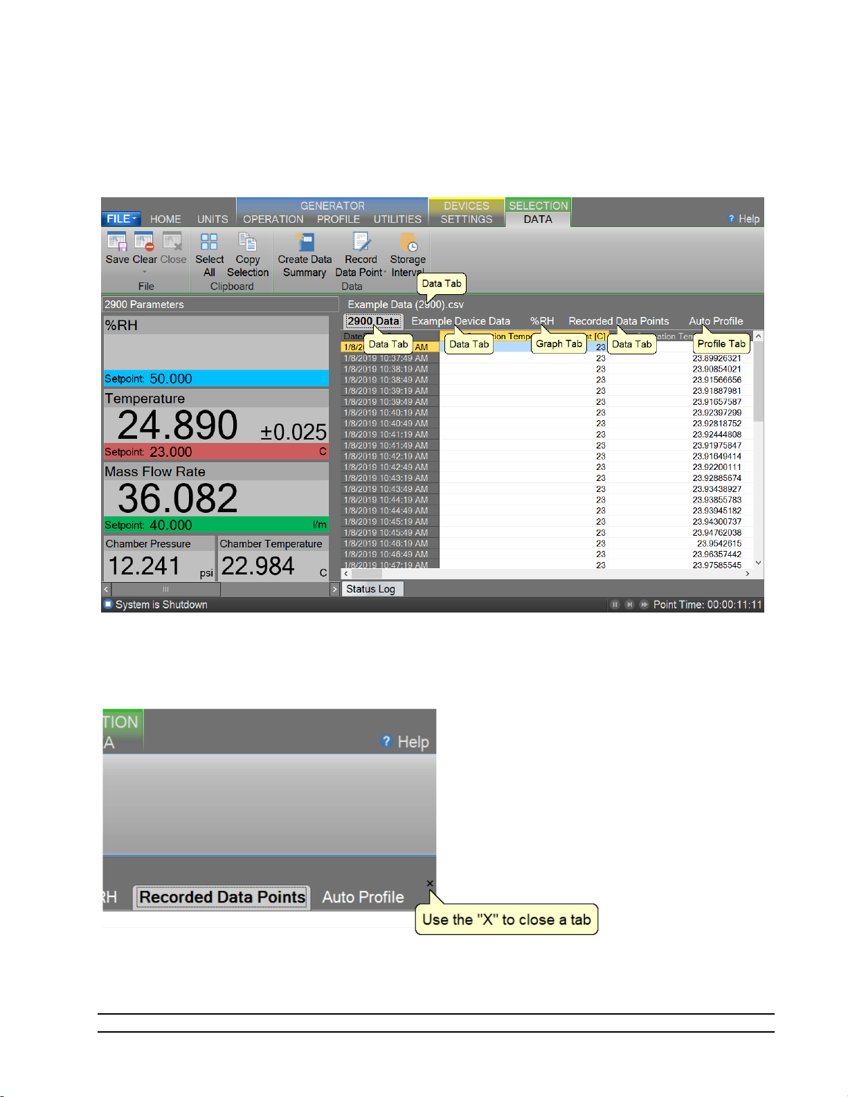
4.3 DATA AND GRAPH TAB GROUP
The Data and Graph Tab Group is located in the middle right of the application and can contain data, graph,
and profile tabs. Data and Graph tabs are fixed tab style windows that can be selected by clicking the
desired tab labels at the top.
In addition to using the “Close Data” command from the ribbon menu a Data and Graph Tab can be closed
depending on the state of the device or generator using the “X” in the upper right-hand corner.
68
Model 2900 System Manual – Document #OM2900 - Edition 2.0 - June 2022

4.3.1 Data Tabs
Data Tabs contain a spreadsheet type view of the logged data.
For more information, refer to section 8 Data and Data Summary
4.3.2 Graph Tabs
Graph Tabs contain a pictorial view of the logged data.
For more information, refer to section 7 Graphing
4.3.3 Profile Tab
The Profile Tab contains the profile point definitions for an auto profile.
For more information, refer to section 9 Profiling
Model 2900 System Manual – Document #OM2900 - Edition 2.0 - June 2022
69
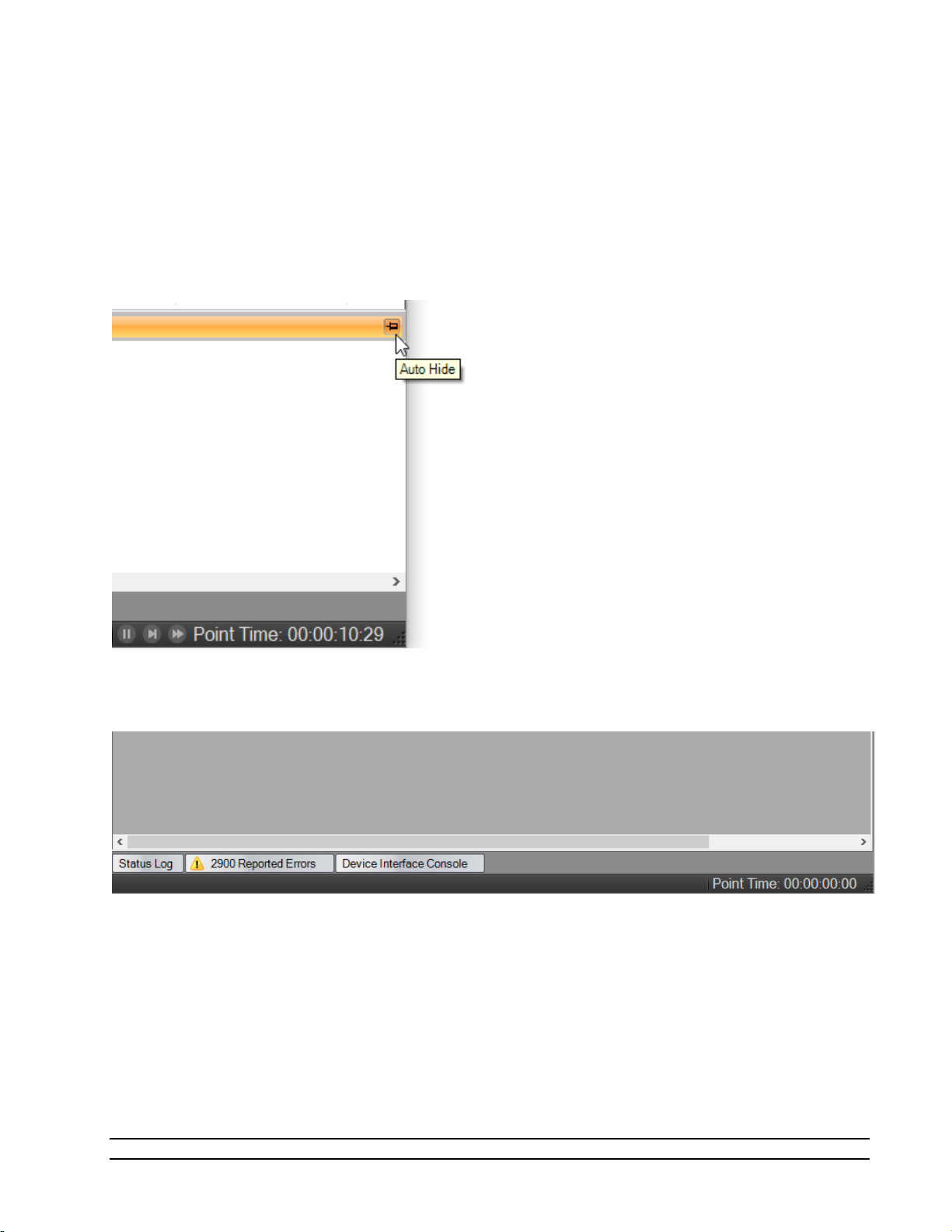
4.4 INFORMATION TAB GROUP
The Information Tab Group is located on the bottom right hand side of the application. This is a docking
style window that can be “pinned” open or allowed to close when not active. An information tab is selected
by clicking its tab label at the bottom of the group. The Information Tab Group contains status information
about the operation of the generator and its connected devices. The group can consist of a Status Log tab,
2900 Reported Errors tab and a 2900 Interface Console tab.
By clicking the pin icon on any information tab, the user can pin or unpin the Information tabs.
By default, the information tabs are unpinned, and they will automatically hide.
70
Model 2900 System Manual – Document #OM2900 - Edition 2.0 - June 2022
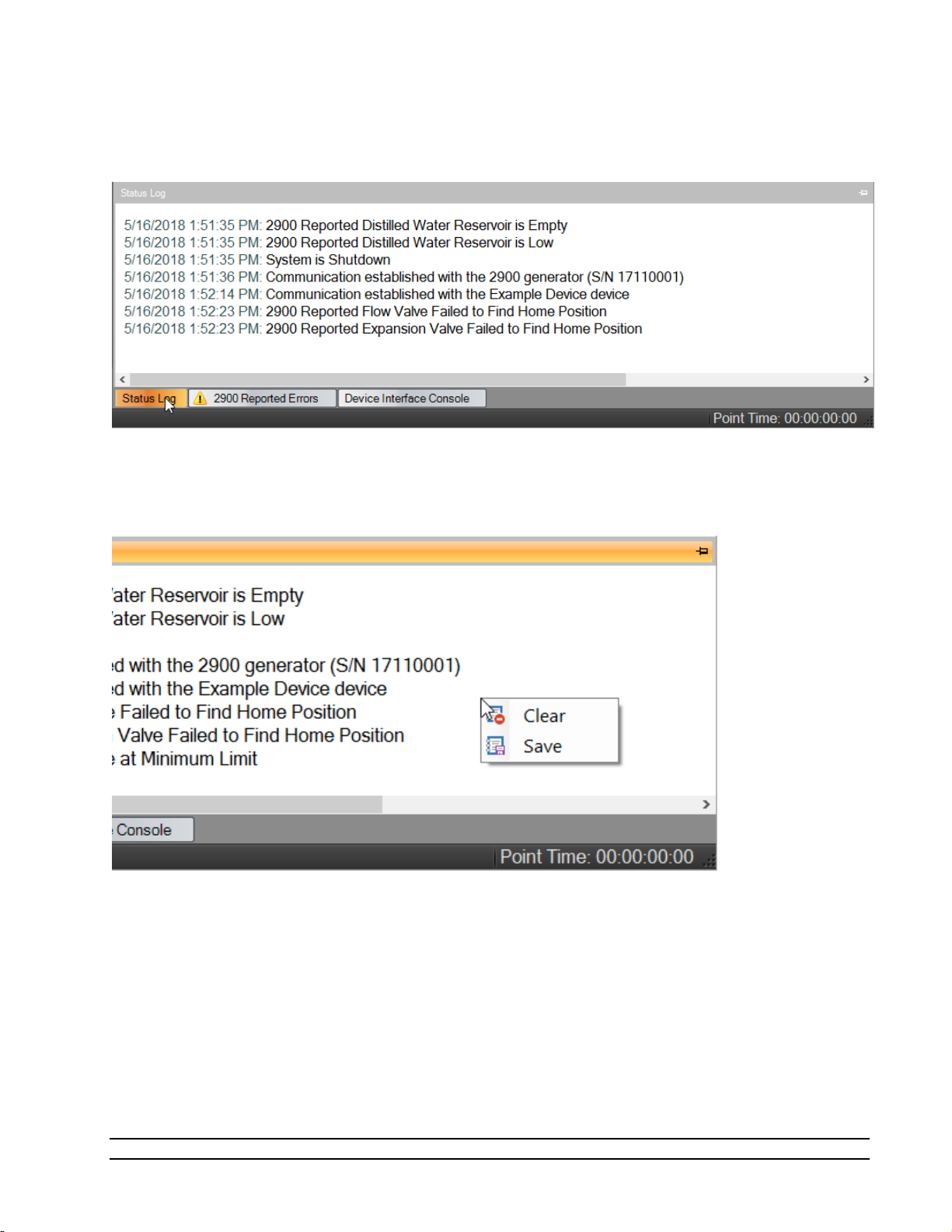
The user can access the hidden tabs by clicking the desired information tab label at the bottom.
All Information Tabs have a context menu that is displayed by long pressing or right clicking in the tab. The
context menu allows quick access to functions that can clear and save the information.
Model 2900 System Manual – Document #OM2900 - Edition 2.0 - June 2022
71
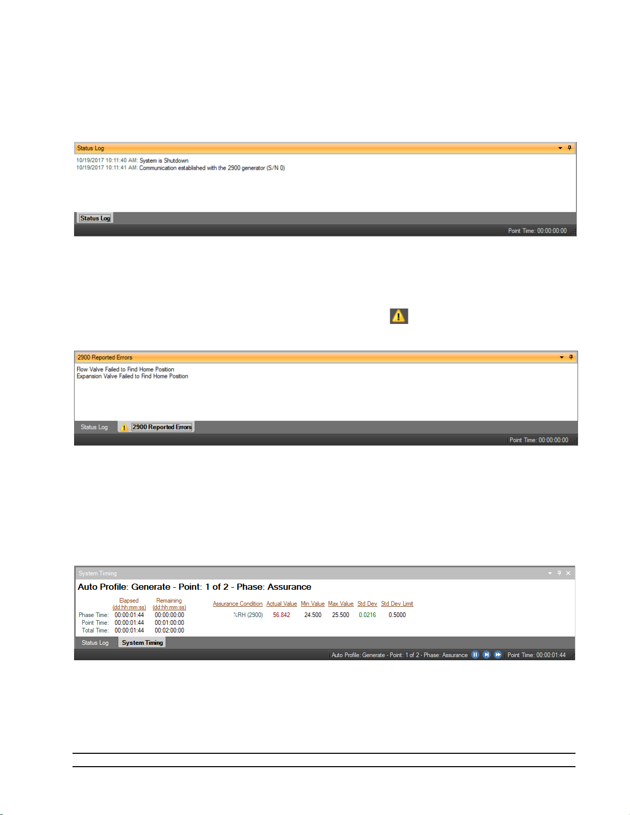
4.4.1 Status Log
The Status Log tab contains chronological information about the system status, changes in operational
modes, changes in setpoints, and runtime errors due to communication or mechanical difficulties
encountered by the generator.
4.4.2 2900 Reported Errors
The 2900 Reported Errors tab only appears when the 2900 reports an error. This is a very important
information tab because it reports 2900 system errors to the user. These types of errors can cause the 2900
to shutdown and require immediate attention by the operator. The icon will be displayed to help draw
the attention of the user to the reported 2900 errors.
4.4.3 System timing
The System Timing tab shows information about the current timing associated with the current operation
such as elapsed run time at current conditions. This window may be shown at any time by clicking the
“Point Time” in the status bar and is automatically shown when an Auto Profile is started. The tab gives
detailed information on the Auto Profile as it runs. Elapsed and remaining Phase, Point and Total time are
listed along with the detailed assurance conditions values and tolerances.
4.4.4 2900 Interface Console
The 2900 Interface Console tab allows the user to send and receive commands to and from the 2900. The
console tab is opened by selecting “Interface Console” from the Utilities Menu Tab. This feature is intended
for factory support and should not be used regularly by the user of the 2900.
72
Model 2900 System Manual – Document #OM2900 - Edition 2.0 - June 2022

4.4.5 Device Interface Console
The Device Interface Console tab allows the user to view the commands being sent to and received from any
given connected device. The device console tab is opened by selecting “Interface Console” from the Settings
Menu Tab whenever a device is connected.
The user can select which connected device to view using the drop-down selection at the top of the tab.
The data sent to the device is indicated by a bold “Sent:” label in the lower text area of the console tab.
The data received from the device is indicated by a bold “Received:” label in the lower text area of the
console tab.
Model 2900 System Manual – Document #OM2900 - Edition 2.0 - June 2022
73

4.5 STATUS BAR
The Status Bar is located on the bottom of the application window. The Status Bar displays the current
Connection and Run Status of the generator, Auto Profile Controls and Status, and current Point Time.
4.5.1 Connection and Run Status
The Connection and Run Status is shown on the left-hand side of the status bar and gives the user a quick
visual and textual reference to the current state of the Model 2900 Humidity generator. As new events are
recorded into the Status Log, the event will be displayed for a short period of time in the status bar to
inform the user of the new event.
4.5.1.1 Disconnected
The status bar will show an “unplugged” icon and “Disconnected” when the 2900 is not connected to
ControLog.
4.5.1.2 Generating
The status bar will show a green forward arrow icon and “System is generating” when the 2900 is
generating.
If the 2900 is reporting an error, the green forward arrow icon will also appear with a small yellow warning.
4.5.1.3 Shutdown
The status bar will show a blue stop icon and “System is shutdown” when the 2900 is shutdown.
If the 2900 is reporting an error, the blue stop icon will also appear with a small yellow warning.
74
Model 2900 System Manual – Document #OM2900 - Edition 2.0 - June 2022

4.5.1.4 New Event
During any state, the most recent status log event will be shown briefly in the status bar.
4.5.2 Auto Profile Controls and Status
The Auto Profile Controls and Status are shown on the right-hand side of the status bar and give the user
quick control and status over a running profile. The Auto Profile consists of three status parts and three
control parts.
For more information, refer to section 9 Auto Profiling
4.5.2.1 Auto Profile Controls
The Auto Profile controls consist of a “Pause” button, “Next Point” button and a “Next Phase” button.
4.5.2.2 Auto Profile Status
The Auto Profile status consists of the generator “Run Mode” for the current profile point, the “Profile
Point” the system is currently running and the “Phase” of the current point.
Model 2900 System Manual – Document #OM2900 - Edition 2.0 - June 2022
75

4.5.3 Current Point Time
The Current Point Time is shown on the right-hand side of the status bar and gives the user a quick display to
the amount of time the system has been at point. Point Time is not the amount of time at setpoint but
simply the amount of time since the last setpoint or mode change.
The user can click the point time to open the system timing tab.
4.5.4 Set Date and Time
The user can change the current system date and time through the status bar context menu.
– To avoid time stamp confusion only change the system date and time when the generator is
Note
shutdown and not recording data.
Start by long pressing or right clicking anywhere within the status bar to open the status bar context menu.
76
Model 2900 System Manual – Document #OM2900 - Edition 2.0 - June 2022

Select “Set Date and Time” from the context menu to open the system Date and Time dialog.
Model 2900 System Manual – Document #OM2900 - Edition 2.0 - June 2022
77

5 FLUID LEVELS
The Fluid Levels dialog allows the user to view the current level of the Water Reservoir along with the states
of the liquid level sensors.
To access the Fluid Level dialog, select Reservoir Level from the Generator Utilities menu.
For more information, refer to section 12.4 Fluid System
5.1 WATER RESERVOIR LEVEL
The Water Reservoir Level is the measured distilled water level in the water reservoir and is an indication of
the amount of distilled water available to fill the Pre-Saturator during operation. This is the distilled water
supply used by the generator to generate a humidified gas output.
78
Model 2900 System Manual – Document #OM2900 - Edition 2.0 - June 2022

5.1.1 Fill Water Reservoir
a) Remove the reservoir fill port cap located on the top panel of the system. Attach the provided
funnel to fill port.
CAUTION!
THE SYSTEM MUST BE SHUT DOWN AND VENTED OF PRESSURE
BEFORE THE WATER RESERVOIR CAN BE FILLED
b) Add up to 1 gallon (3.8 liters) of double distilled (or better) water until the Water Reservoir Level
indicates full. A small funnel may be useful. Add the water slowly so as not to overfill the reservoir.
c) Remove funnel and replace fill port cap, finger tighten, and proceed with operation.
Note
- If the water reservoir is out of water and the system shuts down with the “Unable to Fill Pre-
Saturator Reservoir” error you must refill the water reservoir to a minimum of 75% full before trying
to generate again. It is recommended to always fill the reservoir to 100% whenever filling is required.
It is possible to overfill the reservoir depending on the rate the reservoir is filled. The system will indicate an
over filled condition by displaying the tank level in red. In most cases this is not an issue but if the system is
filled over 110% there is a possibility that the pre-saturator will become over filled. It is best to drain the
pre-saturator and let it refill. Refer to section 13.1 DRAIN PRE-SATURATOR
.
Model 2900 System Manual – Document #OM2900 - Edition 2.0 - June 2022
79

5.2 LIQUID LEVEL SENSORS
Liquid Level Sensors indicate a discrete state of the given sensor. Red indicates no water sensed and green
indicates water is sensed. The exception is the pump water circulation Flow Switch (FS1) where red
indicates no fluid flow and green indicates the presence of fluid flow.
5.2.1 Pre-Saturator Level
The Pre-Saturator Level is a discrete indication of the Pre-Saturator water level. When the system is
shutdown, a click of the label or indicator will start a manual filling process for the Pre-Saturator. This
feature is mainly used after the water reservoir tank is filled or when the Pre-Saturator has been drained.
Note - The system will automatically fill the Pre-Saturator as needed while generating.
Click the “Pre-Saturator Level” label and the system will open the pre-saturator fill solenoid to allow distilled
water to flow from the reservoir to the Pre-Saturator. The system will indicate that it is filling with the
message “Filling Pre-Saturator” and will continue the fill process until the Pre-Saturator is full as indicated by
the Pre-Saturator Level indication turning green. Once filled the system will automatically stop and close the
pre-saturator fill solenoid. The user has the option to cancel the filling operation at any time by clicking the
label or indicator again.
80
Model 2900 System Manual – Document #OM2900 - Edition 2.0 - June 2022

5.2.2 Flow Switch
The Flow Switch (FS1) is a discrete indication of the water circulation pump operating correctly. When the
flow switch indication is red, water is not being circulated within the system. Water will only be circulated
when operating in the Generate mode.
Refer to section 2.12.3.1 Chamber Fluid Filling Procedure
for information on adding fluid to the
chamber jacket
Refer to section 12.4 Fluid System for information on the system’s fluid system.
Model 2900 System Manual – Document #OM2900 - Edition 2.0 - June 2022
81

6 CALIBRATION
Proper calibration of the temperature and pressure transducers is critical to the accuracy of the generated
humidity. Each time a probe or transducer is calibrated its current calibration coefficients and calibration
data are stored to disk. Calibration of the system requires the following support equipment:
Note - The following information is provided as a recommendation for the calibration of the Thunder
Scientific 2900 Humidity Generator. It is the user’s responsibility to ensure the standards used meet/exceed
their organization’s specific test limit/guard banding requirements.
1) Temperature, range 0 to +72 °C (standard range) or -10 to +72 °C (low temp range):
• Precision temperature bath of specified range with a liquid medium (recommend FC-77
Fluorinert, a 3M product).
Note - Less stable baths may require the use of a thermal block.
• Standard or reference thermometer (PRT) of specified range with an accuracy low
enough to assure ±0.027 °C test limit or guard band.
2) Chamber Pressure, range ambient to 17 psi absolute:
• Stable static gas pressure source.
• Standard or reference pressure gauge with an accuracy low enough to assure ±0.020 %
of reading test limit or guard band.
3) Saturation Pressure, range ambient to 160 psi absolute:
• Stable static gas pressure source.
• Standard or reference pressure gauge with an accuracy low enough to assure ±0.020 %
of full-scale (160 *± 0.020% = ±0.032 psi absolute) test limit or guard band.
5) Flow, range 0 to 50 standard liters/min:
• Reference flow meter with an accuracy low enough to assure ±5.0 % of full-scale (50.0
*± 5.0% = ±2.5 liter/min) test limit or guard band.
Note – Flow is standardized with a reference temperature of 70.0 °F at 760 torr
6.1 TEMPERATURE CALIBRATION
The temperature calibration procedure is used in conjunction with a precision temperature bath for
calibration of the temperature probes. By using the temperature bath to generate up to five known
temperatures, all coefficients will be calculated automatically by the computer and used to update the
system calibration. Calibration reports will be generated and can be saved for each of the temperature
probes at the conclusion of each calibration sequence.
Refer to drawings: 18D29901-1, 18D29901-3, 18D29901-4
82
Model 2900 System Manual – Document #OM2900 - Edition 2.0 - June 2022

6.1.1 Equipment Required
1. Precision Temperature Bath.
2. Standard or Reference thermometer.
3. #10 Torx Driver
4. Temp Probe Tool #20M00305
5. Long nose pliers
6. 1/2” & 9/16” wrenches
6.1.2 Calibration Procedure
For safety purposes, perform a shutdown, perform a shutdown system, switch system "POWER" to OFF and
remove power cord before removing any panel or air supply line.
1. Disconnect the air supply line to generator and remove air supply inlet fitting.
2. Remove the top, left and rear panels.
3. Remove temperature probes to be calibrated:
Note
- The Cabinet Temp (RTD5) does not require calibration and can't be removed.
• Chamber Temperature Probe (RTD4): Remove the access port insulation. Using the Long Nose
Pliers, grasp the rubber cork and pull straight up. Remove the probe by feeding the cable and
probe up and through the chamber access port.
• Saturation Temperature Probe (RTD1): Remove the access port insulation. Using the “Temp
Probe Tool”, loosen the captive nut ½ turn counterclockwise (do not remove captive nut) and
remove the probe by pulling straight up from the access port fitting.
• Expansion Valve Temperature Probe (RTD3): To access to the Expansion Valve Temperature
Probe, remove the expansion valve access cover. Remove the expansion valve insulation. Using
the “Temp Probe Tool”, loosen the knurled compression nut ½ turn counterclockwise (do not
remove captive nut). Gently pull the probe straight up to remove probe.
• Presaturator Temperature Probe (RTD2): Remove the Presaturator Temperature Probe by
pulling the “Probe Captive Stay” straight down then pull the Presaturator Temperature Probe
straight down from the thermal well. Pull the cable and probe up and through the 2900 frame
corner
4. Bring a precision temperature bath with reference thermometer to the system. Pull the split tube
temperature probe covering from the frame corners to allow the temperature probes to reach the
temperature bath. Install the temperature probes into temperature bath.
5. Switch main console power ON. Wait a few moments for the system to initialize and for the
Control/Display screen to appear.
Model 2900 System Manual – Document #OM2900 - Edition 2.0 - June 2022
83

CAUTION!
DO NOT ENABLE CONTROL BY SELECTING GENERATE WITH ANY
TEMPERATURE PROBE REMOVED FROM THE SYSTEM.
From the Units menu tab select the desired temperature units for calibration. Once calibration has begun,
the units should not be changed again until the calibration is complete.
Select
Generator Calibration from the Utilities menu tab to open the Calibration Wizard.
84
Model 2900 System Manual – Document #OM2900 - Edition 2.0 - June 2022

Select, “Take “As Received” points”. This will allow the user to take points with the current calibration to
determine out of tolerance. After all “As Received” points have been taken the user will be asked whether
they want to calculate new calibration coefficients.
Set the type of calibration to Temperature.
Model 2900 System Manual – Document #OM2900 - Edition 2.0 - June 2022
85
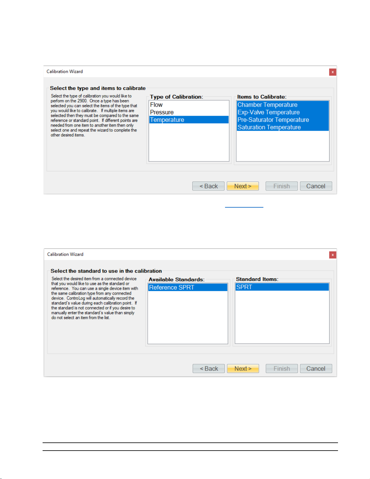
Select the temperature probes to be calibrated. In most case this will be all four probes, but the user is able
to calibrate any given probe separately or together.
If the temperature standard is a connected device (refer to section 9 Connections
), you may select it for the
calibration. You can use a single device item with the same calibration type from any connected device.
ControLog will automatically record the standard’s value during each calibration point. If the standard is not
connected or if you desire to manually enter the standard’s value, then simply do not select an item from
the list.
86
Model 2900 System Manual – Document #OM2900 - Edition 2.0 - June 2022
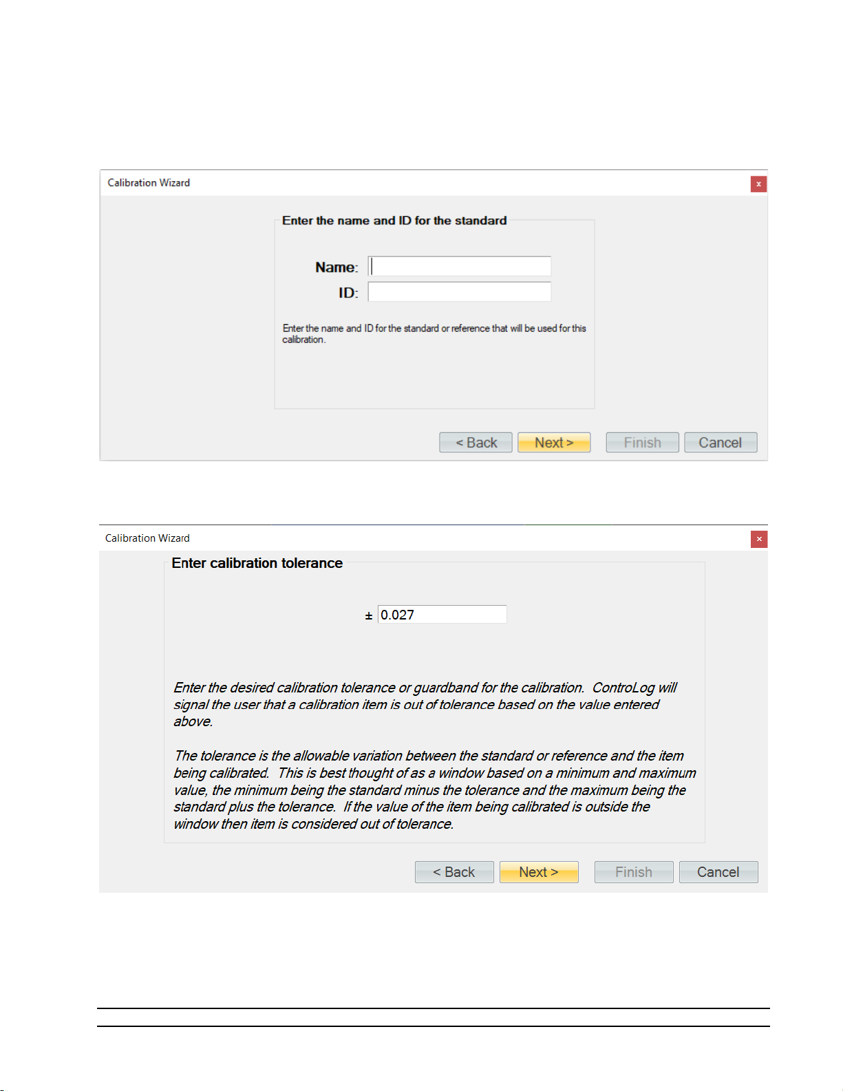
Enter the Name and ID of the standard being used. This information will be populated on the calibration
report. Selecting “Next” without entering a Name will result in ControLog giving the standard a generic
name.
Enter the desired calibration tolerance or guard band for the calibration. ControLog will signal the user that
a calibration item is out of tolerance based on the value entered above.
The tolerance is the allowable variation between the standard or reference and the item being calibrated.
This is best thought of as a window based on a minimum and maximum value, the minimum being the
standard minus the tolerance and the maximum being the standard plus the tolerance. If the value of the
item being calibrated is outside the window, then the item is considered out of tolerance.
Model 2900 System Manual – Document #OM2900 - Edition 2.0 - June 2022
87

An out of tolerance condition will be indicated by a red circle with an exclamation point for the out of
tolerance probe in the Error column.
Enter the sample size used to perform the standard deviation calculation. The sample size is the given time
that ControLog will use to determine which data points to use to determine the standard deviation of each
probe.
Note
- The number of points used will be based on the data storage rate you have selected
along with the desired sample size. For example, if the data storage rate is every 30 seconds
then a sample size of 10 minutes will result in 20 points being used to calculate the standard
deviation.
88
Model 2900 System Manual – Document #OM2900 - Edition 2.0 - June 2022

Select the number of points you would like to take for this “As Received” calibration. Each point defines
what the “true” value is at a given point based on the standard or reference value. The number of points
determines the degree of the polynomial used to align or correct the generator with the standard or
reference.
Five calibration points are recommended for all temperature probes using the following temperature points:
• 0 °C, 17.5 °C, 35 °C, 52.5 °C, and 70 °C.
Note - The specific points can be different than those listed above. Use best metrology practices when
determining which the points to take.
Using the temperature bath, generate the first temperature point (0 °C). If the standard is not a connected
device, then ControLog will ask for the value before taking the point. You can also enter a standard or
reference value before taking a point by clicking the cell in the “Standard” row and “Value” column. This is
useful for seeing error values before a point is taken.
Model 2900 System Manual – Document #OM2900 - Edition 2.0 - June 2022
89

Once the readings are stable, click the “Take Point” button. Then once a point has been taken the wizard
will automatically advance to the next point.
Tip - Use the “Next” and “Back” button to navigate between taken points. You can clear and retake
a point by simply clicking the “Clear Point” button and then repeat the process to retake the point.
90
Model 2900 System Manual – Document #OM2900 - Edition 2.0 - June 2022

Using the temperature bath, generate the second temperature point (17.5 °C). Once the readings are stable
enter the standards value and click the “Take Point” button.
Using the temperature bath, generate the third temperature point (35 °C). Once the readings are stable
enter the standards value and click the “Take Point” button.
Model 2900 System Manual – Document #OM2900 - Edition 2.0 - June 2022
91

Using the temperature bath, generate the fourth temperature point (52.5 °C). Once the readings are stable
enter the standards value and click the “Take Point” button.
Using the temperature bath, generate the last temperature point (70 °C). Once the readings are stable
enter the standards value and click the “Take Point” button.
92
Model 2900 System Manual – Document #OM2900 - Edition 2.0 - June 2022

When all temperature points have been entered, ControLog will advance to the “As Received” calibration
report. Each temperature probe will appear in its own tab and contains the data for each calibration point
along with the coefficients used at the time the points were taken.
Clicking the “Save Reports” button will open a file dialog to save the report. The default file location is
…Documents\Thunder Scientific\2900 ControLog\Reports\. If the report is saved in an Excel format, then
each probe will appear in its own tab within the workbook. The user needs to save in a text-based format
then a file for each probe calibrated will be created.
Model 2900 System Manual – Document #OM2900 - Edition 2.0 - June 2022
93
 Loading...