

Thunder Scientific series 3900 Operation And Maintenance Manual

OPERATION AND MAINTENANCE MANUAL
LOW HUMIDITY GENERATOR
SERIES 3900
®

MADE IN USA
SERIES 3900
LOW HUMIDITY GENERATOR
OPERATION AND
MAINTENANCE MANUAL
Copyright © 1993-2017
THUNDER SCIENTIFIC CORPORATION
623 WYOMING BLVD. SE
ALBUQUERQUE, NEW MEXICO 87123-3198
www.thunderscientific.com
Printed 2017
Tel: 505.265.8701 FAX: 505.266.6203
E-mail: support@thunderscientific.com
Document Edition 15 September 2017
Firmware Version 2.12
THUNDER SCIENTIFIC® is the registered trademark of Thunder Scientific Corporation.
All the information provided in this document is correct and true at the time of publication.
Thunder Scientific Corporation reserves the right to change any technical data without notice.

Model 3900 Low Humidity Generator

i
TABLE OF CONTENTS
Section 1 - GENERAL INFORMATION
List of Reference Drawings - iv
Warranty
1.1 INTRODUCTION ---------------------------------------------------------------- 1-1
1.2 PRINCIPLE OF OPERATION ------------------------------------------------- 1-1
1.2.1 General Description --------------------------------------------------------- 1-1
1.2.2 Humidity Formulas --------------------------------------------------------- 1-1
1.2.2.1 Saturation Vapor Pressure, e ----------------------------------------- 1-2
1.2.2.2 Enhancement Factor, ƒ ----------------------------------------------- 1-3
1.2.2.3 Frost Point -------------------------------------------------------------- 1-4
1.2.2.4 Dew Point -------------------------------------------------------------- 1-5
1.2.2.5 Parts Per Million by Volume, PPMv ------------------------------- 1-5
1.2.2.6 Parts Per Million by Weight, PPMw ------------------------------- 1-6
1.2.2.7 Relative Humidity, %RH --------------------------------------------- 1-6
1.3 SPECIFICATIONS --------------------------------------------------------------- 1-7
1.3.1 Facility Requirements ------------------------------------------------------ 1-7
1.3.2 Environmental --------------------------------------------------------------- 1-7
1.4 COMPUTER/CONTROL SYSTEM ------------------------------------------ 1-8
1.4.1 General Description --------------------------------------------------------- 1-8
1.4.2 Computer/Control System Configuration ------------------------------- 1-8
1.4.2.1 Central Processing Unit (CPU) -------------------------------------- 1-8
1.4.2.2 Liquid Crystal Display (LCD) --------------------------------------- 1-9
1.4.2.3 Liquid Crystal Display Driver --------------------------------------- 1-9
1.4.2.4 Keypad ------------------------------------------------------------------ 1-9
1.4.2.5 Memory Card ---------------------------------------------------------- 1-9
1.4.2.6 Analog to Digital Converter (A/D) --------------------------------- 1-9
1.5 ELECTRICAL SYSTEM ------------------------------------------------------- 1-10
1.5.1 AC Power Distribution ---------------------------------------------------- 1-10
1.5.2 Power Supply ±15, +5 VDC ---------------------------------------------- 1-10
1.5.3 Power Supply +24 VDC -------------------------------------------------- 1-10
1.5.4 Analog Inputs --------------------------------------------------------------- 1-11
1.5.4.1 Temperature Measurement ------------------------------------------ 1-11
1.5.4.2 Test Pressure Transducer -------------------------------------------- 1-11
1.5.4.3 Low Range Saturation Pressure Transducer ---------------------- 1-12
1.5.4.4 High Range Saturation Pressure Transducer --------------------- 1-12
1.5.4.5 Gas Supply Pressure Transducer ----------------------------------- 1-12
1.5.4.6 Mass Flow Meter ----------------------------------------------------- 1-12
1.5.5 Control Logic --------------------------------------------------------------- 1-13
1.5.5.1 Gas Supply Solenoid Valve ----------------------------------------- 1-13
1.5.5.2 Fluid Pump Purge Solenoid Valve --------------------------------- 1-13

ii
1.5.5.3 Saturator Vent/Purge Solenoid Valve ----------------------------- 1-13
1.5.5.4 Pressure Select Solenoid Valve ------------------------------------ 1-13
1.5.5.5 Saturator Refrigerant Solenoid Valve ----------------------------- 1-14
1.5.5.6 Saturator Inlet/Outlet Heater --------------------------------------- 1-14
1.5.5.7 Saturator Fluid Heater ----------------------------------------------- 1-14
1.5.5.8 Saturator Fluid Circulation Pump --------------------------------- 1-14
1.5.5.9 Saturator Refrigeration Compressors ----------------------------- 1-14
1.5.5.10 Flow Control Valve ------------------------------------------------------- 1-15
1.5.5.11 Expansion Valve ----------------------------------------------------------- 1-15
1.5.5.12 Expansion Valve Heater -------------------------------------------------- 1-15
1.6 PNEUMATIC SYSTEM ------------------------------------------------------- 1-16
1.7 FLUID SYSTEMS -------------------------------------------------------------- 1-16
1.7.1 Saturator Fluid Systems --------------------------------------------------- 1-16
1.8 REFRIGERATION ------------------------------------------------------------- 1-17
1.8.1 Saturator Refrigeration ---------------------------------------------------- 1-17
Section 2 - INSTALLATION
2.1 GENERAL ------------------------------------------------------------------------- 2-1
2.2 FACILITIES REQUIRED ------------------------------------------------------- 2-1
2.2.1 Floor Space ------------------------------------------------------------------- 2-1
2.2.2 Power -------------------------------------------------------------------------- 2-1
2.2.3 Gas Supply -------------------------------------------------------------------- 2-1
2.3 PREPARATION ------------------------------------------------------------------ 2-1
2.3.1 Methanol Filling Procedure ------------------------------------------------ 2-2
2.3.2 Vent Muffler ------------------------------------------------------------------ 2-3
2.4 POSITIONING AND LEVELING --------------------------------------------- 2-3
2.5 FACILITY CONNECTIONS ---------------------------------------------------- 2-3
2.5.1 Gas Supply -------------------------------------------------------------------- 2-3
2.5.2 Pressure Vent ----------------------------------------------------------------- 2-3
2.5.3 AC Power --------------------------------------------------------------------- 2-3
Section 3 - OPERATION
3.1 GENERAL ------------------------------------------------------------------------- 3-1
3.2 STANDARD OPERATING PROCEDURES -------------------------------- 3-1
3.2.1 Power-Up --------------------------------------------------------------------- 3-1
3.2.2 Control/Display Screen ----------------------------------------------------- 3-1
3.2.2.1 Changing the Display Contrast -------------------------------------------- 3-3
3.2.3 Changing Setpoints ---------------------------------------------------------- 3-4
3.2.3.1 Example Setpoint Change -------------------------------------------- 3-5
3.2.4 Control Modes --------------------------------------------------------------- 3-7
3.2.4.1 Changing Control Mode ---------------------------------------------- 3-8
3.2.5 Purging ---------------------------------------------------------------------- 3-10

iii
3.2.5.1 Purging Procedure ---------------------------------------------------- 3-11
3.2.6 Saturator Clear -------------------------------------------------------------- 3-12
3.2.6.1 Saturator Clear Procedure ------------------------------------------- 3-12
3.2.7 Generating ------------------------------------------------------------------- 3-13
3.2.7.1 Generating Procedure ------------------------------------------------ 3-14
3.2.7.2 Example Instrument Set-up ----------------------------------------- 3-15
3.2.8 Saturator Fill ---------------------------------------------------------------- 3-16
3.2.8.1 Saturator Fill Procedure --------------------------------------------- 3-16
3.2.9 Stopping --------------------------------------------------------------------- 3-18
3.2.10 Shutdown -------------------------------------------------------------------- 3-19
3.2.11 Changing Gas Supply ------------------------------------------------------ 3-19
3.2.12 Printer (optional) ----------------------------------------------------------- 3-19
3.3 EDITING SYSTEM COEFFICIENTS AND PARAMETERS ---------- 3-20
3.3.1 Edit Mode ------------------------------------------------------------------- 3-20
3.3.2 Coefficients and Parameters ---------------------------------------------- 3-22
3.3.2.1 Temperature Coefficients ------------------------------------------- 3-22
3.3.2.2 Reference Resistor Coefficients ------------------------------------ 3-23
3.3.2.3 Pressure Coefficients ------------------------------------------------- 3-23
3.3.2.4 Flow Coefficients ----------------------------------------------------- 3-24
3.3.2.5 Console Port Parameters -------------------------------------------- 3-25
3.3.2.6 Printer Port Parameters ---------------------------------------------- 3-26
3.3.2.7 Time and Date -------------------------------------------------------- 3-26
3.3.2.8 Miscellaneous User Parameters ------------------------------------ 3-27
Section 4 - CALIBRATION AND MAINTENANCE
4.1 GENERAL ------------------------------------------------------------------------ 4-1
4.2 CALIBRATION ------------------------------------------------------------------ 4-1
4.2.1 A/D Card --------------------------------------------------------------------- 4-2
4.2.2 Temperature Calibration --------------------------------------------------- 4-2
4.2.2.1 Test Temperature Calibration Procedure --------------------------- 4-3
4.2.2.2 Saturation Temperature Calibration -------------------------------- 4-7
4.2.3 Pressure Transducer Calibration ----------------------------------------- 4-11
4.2.3.1 Saturator and Test Pressure Calibration Procedure -------------- 4-12
4.2.3.2 Supply Pressure Transducer Calibration -------------------------- 4-16
4.2.4 Flow Meter Calibration --------------------------------------------------- 4-18
4.2.4.1 Flow Calibration Procedure ----------------------------------------- 4-18
4.2.5 Printing Condensed Coefficient Report --------------------------------- 4-22
4.3 ROUTINE MAINTENANCE -------------------------------------------------- 4-23
4.3.1 Console Intake: Monthly -------------------------------------------------- 4-23
4.3.2 7 Micron Gas Input Filter: Yearly --------------------------------------- 4-23
4.4 SERVICING REFRIGERATION AND FLUID SYSTEMS -------------- 4-24
4.4.1 Fault Isolation and Diagnosis --------------------------------------------- 4-24
4.4.1.1 Moisture In Low Stage----------------------------------------------- 4-24
4.4.1.2 Oil In Low Stage Evaporator --------------------------------------- 4-25

iv
4.4.2 Refrigerant Charge -------------------------------------------------------- 4-25
4.4.3 Saturator Fluid System ---------------------------------------------------- 4-25
4.4.4 Methanol System Drain/Fill Procedure --------------------------------- 4-25
4.5 ERROR CODES AND TROUBLESHOOTING --------------------------- 4-27
Section 5 - PARTS LIST
5.1 3900 PARTS LIST ---------------------------------------------------------------- 5-1
LIST OF REFERENCE DRAWINGS
DRAWING # DRAWING TITLE
94D39901 -------------------------Mechanical/ Utility
95D39902 -------------------------Component Locations
95D39903 -------------------------Card Cage and Card Locations
95D39904 -------------------------3900 Bus Diagram
95D39905 -------------------------Electrical Sub-Panel Layout
95S39906 --------------------------Terminal Layout
95S39907 --------------------------AC/DC Power Schematic
95S39908 --------------------------Solid State Relay Module Board
95S39909 --------------------------Compressor / Heater / Alarm Schematic
95S39910 --------------------------Flow Valve Drive Schematic
95S39911 --------------------------Expansion Valve Drive Schematic
95S39912 --------------------------Temperature Probe / Transducer Schematic
95S39913 --------------------------Display Block Diagram
95D39914 -------------------------RS-232C Console / Printer
95S39915 --------------------------Pneumatic System (Generate Mode)
95S39916 --------------------------Pneumatic System (Purge Mode)
95S39917 --------------------------Refrig And Fluid Flow - Saturator
95S39918 --------------------------Test Temp/Test Press Xducer Schematic
08S39921 --------------------------3900 Card Cage Schematic
08D39922 -------------------------Methanol Fill Level Drawing
15A39504 -------------------------4-Port Sample Cell Manifold

WARRANTY
Thunder Scientific Corporation (TSC) warrants, to the Buyer, the Product
manufactured by TSC to be free of defects in material and workmanship
under normal use and service and to be free from inadequate mechanical
design when operated within the specified design limitations for a period
of one year from date of acceptance. TSC's obligation under this warranty
shall be limited to the following: the Product is returned to TSC with
transportation charges prepaid and that TSC's examination reveals the
Product to be defective. TSC, at its option, shall either refund to the Buyer
the purchase price of the product or repair or replace at TSC's plant, any
part or parts of the Product which is or are defective. This warranty shall
not apply to any Product which has been maintained, handled, stored,
repaired or altered in any manner, or by anyone other than an authorized
TSC representative, so as to affect adversely such Product or which has
been subject to improper installation, misuse, negligence, accident or
corrosion. THIS WARRANTY IS EXCLUSIVE AND IN LIEU OF ANY
WARRANTY OF MERCHANTABILITY, FITNESS FOR A
PARTICULAR PURPOSE OR ANY OTHER WARRANTY, WHETHER
EXPRESS OR IMPLIED, AND ALL OTHER LIABILITIES AND
OBLIGATIONS ON THE PART OF TSC; TSC SHALL NOT BE
LIABLE FOR ANY OTHER CLAIMS OR DAMAGES, EITHER
DIRECT OR CONSEQUENTIAL, ARISING DIRECTLY OR
INDIRECTLY OUT OF SUPPLYING THE PRODUCT. All warranties,
express or implied, with respect to any device or component not
manufactured by TSC but incorporated into its Product are the
responsibility of the original manufacturer and shall not affect or apply to
TSC.
Thunder Scientific®
Corporation
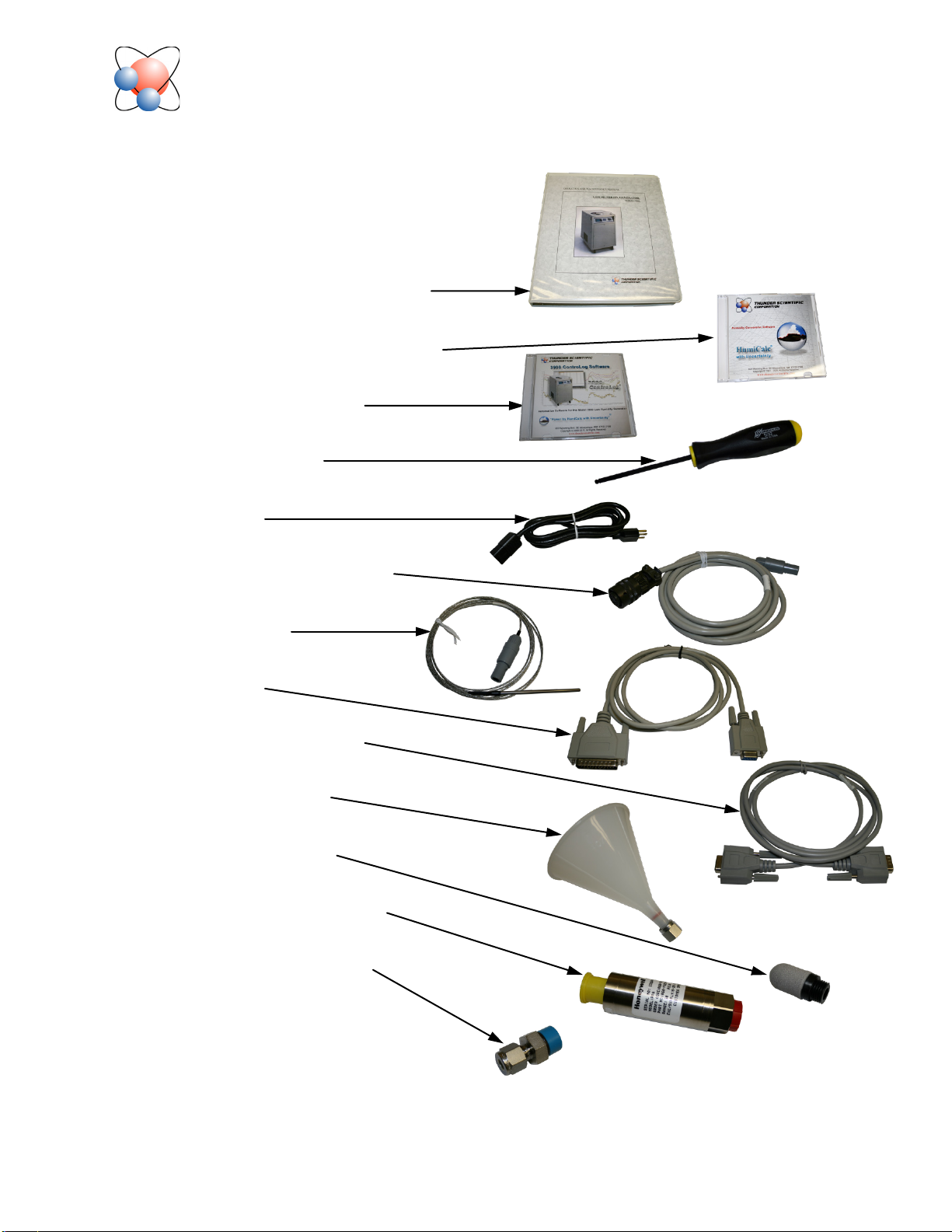
3900 Item Check List
1. Certificate of Calibration (In Manual)
2. Operation and Maintenance Manual
3. HumiCalc® with Uncertainty Software
4. 3900 ControLog® Software
5. 5/32” Ball Driver Tool
6. Power Cable
7. Transducer Test Pressure Cable
8. Test Temp Cable
9. Printer Cable
10. Computer IO Control Cable
11. Pure Water Fill Funnel
12. 1/4” 30 Micron Muffler
13. Pressure Transducer 0 – 50 Psi
14. 1/4” Swage x 9/16” – 18 STD
Thunder Scientific Corporation Web: www.thunderscientific.com
623 Wyoming Blvd. SE E-mail: support@thunderscientific.com
Albuquerque, NM 87123 Phone: 1-800-872-7728
Suomi
English
Tämä tuote noudattaa WEEE-direktiivin (2002/96/EY)
merkintävaatimuksia. Kiinnitetty etiketti osoittaa, että tätä
sähkö-/elektroniikkalaitetta ei saa hävittää kotitalousjätteissä.
Tuoteluokka: Viitaten WEEE-direktiivin liitteessä I mainittuihin
laitteisiin, tämä tuote on luokiteltu luokan 9 “Tarkkailu- ja
ohjauslaitteet” -tuotteeksi.
Ei saa heittää kotitalousjätteiden mukana!
Palauta tarpeettomat tuotteet ottamalla yhteyttä valmistajan
websivustoon, joka mainitaan tuotteessa tai paikalliseen
myyntitoimistoon tai jakelijaan.
Dansk
Dette produkt er i overensstemmelse med kravene om afmærkning
i WEEE-direktivet (2002/96/EC). Det påhæftede mærkat angiver,
at du ikke må bortskaffe dette elektriske/elektroniske produkt via
husholdningsaffald.
Produktkategori: Med reference til kravene i WEEE-direktivets
bilag I klassificeres dette produkt som et produkt til “overvågning
og kontrolinstrumentering” i kategori 9.
MÂ ikke bortskaffes via husholdningsaffald!
Hvis du vil returnere uønskede produkter, skal du besøge
producentens websted, som vises på produktet, eller den lokale
forhandler eller distributør.
This product complies with the WEEE Directive (2002/96/EC) marking
requirements. The affixed label indicates that you must not discard
this electrical/electronic product in domestic household waste.
Product Category: With reference to the equipment types in the
WEEE Directive Annex I, this product is classed as category 9
“Monitoring and Control Instrumentation” product.
Do not dispose in domestic household waste!
To return unwanted products, contact the manufacturer’s web site
shown on the product or your local sales office or distributor.
Français
Ce produit est conforme aux normes de marquage de la directive
DEEE (2002/96/CE). La présence de cette étiquette indique que
cet appareil électrique/électronique ne doit pas être mis au rebut
avec les déchets ménagers.
Catégorie de EEE : Cet appareil est classé comme catégorie 9 parmi
les « instruments de surveillance et de contrôle » en référence aux
types d’équipements mentionnés dans l’Annexe I de la directive DEEE.
Ne pas éliminer avec les autres déchets ménagers !
Pour renvoyer les produits indésirables, contacter le site Web du
fabricant mentionné sur le produit, ou son distributeur ou bureau de
ventes local.
Español
Este producto cumple la Directiva WEEE (2002/96/EC) sobre
requisitos de las marcas. La etiqueta que lleva pegada indica
que no debe desechar este producto eléctrico o electrónico con
los residuos domésticos.
Categoría del producto: con referencia a los tipos de equipo
del anexo I de la Directiva WEEE, este producto está clasificado
como categoría 9 de “Instrumentación de supervisión y control”.
¡No lo deseche con los residuos domésticos!
Para devolver productos que no desee, póngase en contacto con
el sitio Web del fabricante mostrado en el producto, o con la oficina
de ventas o distribuidor local.
PN 2566073, 1/2006
Deutsch
Nederlands
Dieses Produkt stimmt mit den Kennzeichnungsanforderungen
der WEEE-Richtlinie (2002/96/EC) überein. Das angebrachte
Etikett weist darauf hin, dass dieses elektrische/elektronische
Produkt nicht in Hausmüll entsorgt werden darf.
Produktkategorie: In Bezug auf die Gerätetypen in Anhang
I der WEEE-Richtlinie ist dieses Produkt als Kategorie 9
“Überwachungs- und Kontrollinstrument” klassifiziert.
Nicht in Hausmüll entsorgen!
Zur Rückgabe von unerwünschten Produkten die auf dem
Produkt angegebene Website des Herstellers oder die zuständige
Verkaufsstelle bzw. den zuständigen Fachhändler konsultieren.
Italiano
Questo prodotto risponde ai requisiti sull’etichettatura stabiliti
nella Direttiva RAEE (2002/96/CE). Il simbolo apposto indica che
non si deve gettare questo prodotto elettrico o elettronico in un
contenitore per rifiuti domestici.
Categoria del prodotto: con riferimento ai tipi di apparecchiature
elencate nell’Allegato 1 della Direttiva RAEE, questo prodotto
rientra nella categoria 9 “Strumenti di monitoraggio e di controllo”.
Non gettare in un contenitore per rifiuti domestici.
Per restituire prodotti non desiderati, visitare il sito Web del
produttore riportato sul prodotto o rivolgersi al distributore o
all’ufficio vendite locale.
Dit product voldoet aan de merktekenvereisten van de AEEArichtlijn (2002/96/EG). Het aangebrachte merkteken duidt erop dat
dit elektrische/elektronische product niet met het huishoudelijk
afval mag worden afgevoerd.
Productcategorie: Met betrekking tot de apparatuurcategorieën
van bijlage I van de AEEA-richtlijn, valt dit product onder categorie
9 ‘meet- en controle-instrumenten’.
Niet afvoeren met huishoudelijk afval!
Om ongewenste producten te retourneren, neemt u contact op
met de website van de fabrikant die op het product staat vermeld,
of met uw plaatselijke verkoopkantoor of distributeur.
Svenska
Denna produkt uppfyller märkningskraven enligt WEEE Directive
(2002/96/EC). Märkningsetiketten anger att du inte får kassera denna
elektriska/elektroniska produkt tillsammans med vanliga hushållssopor.
Produktkategori: Med hänvisning till utrustningstyperna i
WEEE Directive Annex I, är denna produkt klassad som kategori 9
“Monitoring and Control Instrumentation” (Instrument för
övervakning och styrning).
Får ej kasseras tillsammans med vanliga hushållssopor!
Returnera ej önskvärda produkter genom att gå till tillverkarens
webbplats, vilken anges på produkten, eller till det lokala
försäljningskontoret eller distributören.
Português
Este produto está em conformidade com as exigências de rotulagem
da Directiva WEEE (2002/96/EC). O rótulo afixado indica que o
utilizador não deve deitar este produto eléctrico/electrónico fora
juntamente com o lixo doméstico.
Categoria do produto: No que se refere aos tipos de equipamento listados no Anexo I da Directiva WEEE, este produto está classificado como
produto da categoria 9, “Instrumentação de monitorização e controlo”.
Não deite fora juntamente com o lixo doméstico!
Para devolver produtos indesejados, contacte o fabricante através do
Website constante do produto ou contacte o seu representante de
vendas ou distribuidor local.
Norsk
Dette produktet oppfyller bestemmelsene ifølge WEEE-direktiv
(2002/96/EC) med krav til merking. Påsatt merke viser at det ikke
er tillatt å kassere dette elektriske/elektroniske produktet sammen
med husholdningsavfall.
Produktkategori: På grunnlag av utstyrstypene i WEEEdirektivet, vedlegg I, er dette produktet klassifisert i kategori 9,
“Instrumentering for overvåking og kontroll”.
Må ikke kastes sammen med husholdningsavfall!
Ved behov for returforsendelse av uønskede produkter må du gå
til produsentens nettside som er angitt på produktet, eller du må
kontakte det lokale salgskontoret eller den lokale forhandleren.

Section 1
GENERAL INFORMATION
1.1 INTRODUCTION
The Model 3900 low humidity generating system is a facility capable of producing known
humidity values using the combined fundamental principles of the "two temperature" and
"two pressure" generators developed by NIST. This system is capable of continuously
supplying accurately known humidity values for instrument calibration and evaluation.
When used within the specified frost point range of -95.00 °C to 10.00 °C, the system will
generate manually entered setpoints for days or even weeks unattended.
The 3900 operates using an embedded computer and control system to perform calculation
and control functions. The Computer Control System utilizes a multifunction CPU in
conjunction with other peripheral cards for control and is incorporated into the 3900 low
humidity generator. Peripheral equipment, such as a printer or computer, may be connected
using the bi-directional RS-232C interfaces.
Humidity and temperature setpoint values are input by the operator from the front panel
keypad. The system is then automatically controlled at a setpoint, with visual indications of
system status displayed in real time on the Liquid Crystal Display. The automatic features of
this system allow the 3900 to generate humidity and temperature setpoints completely
unattended, freeing the operating technician from the task of system monitoring and
adjustment.
1.2 PRINCIPLE OF OPERATION
1.2.1 General Description
The Model 3900 humidity generation system is based on the "two temperature - two
pressure" principle. This process involves saturating air or some other gas, such as nitrogen,
with water vapor at a given temperature and pressure. The saturated high pressure gas is then
reduced to test pressure and warmed to test temperature. The indication of saturation
temperature, saturation pressure, test temperature, and test pressure may be used in the
determination of all hygrometric parameters. Humidity generation by this system does not
depend upon measuring the amount of water vapor, but rather is dependent on the
measurements of temperature and pressure alone. The precision of the system is determined
by the accuracy of the temperature and pressure measurements, and on the constancy of them
throughout.
1.2.2 Humidity Formulas
The humidity (or water vapor content) of a gas may be expressed in a variety of ways. The
humidity parameters available with the 3900, and the formulas used to derive them, will be
expressed in terms of the two-temperature two-pressure generator. While some basic
understanding of humidity is helpful, thorough knowledge of the following formulas and
their relationships to the 3900 is not a requirement for successful operation of the generator.
1-1

(
)
+
+
+
−
=
∑
15
.
273ln
15
.273
2
6
0
TD
TC
i
i
i
(
)
( )
++
+
−
=
∑
15.273ln15.273
1
5
0
TDTC
i
i
i
1.2.2.1 Saturation Vapor Pressure, e
Saturation Vapor Pressure (SVP) is the pressure exerted by water vapor alone when in
equilibrium with pure ice or water, and is expressed as a function of temperature only. Since
SVP can be established with respect to either ice or water, two separate formulas are used.
Wexler's1 formula for SVP over water is expressed as
ew(T) = exp
where C0 = -2.9912729 x 10³
C1 = -6.0170128 x 10³
C2 = 1.887643854 x 101
C3 = -2.8354721 x 10⁻²
C4 = 1.7838301 x 10⁻⁵
C5 = -8.4150417 x 10
C6 = 4.4412543 x 10
-10
-13
D = 2.858487
T = temperature of the gas in °C.
For SVP over ice, the equation of Hyland & Wexler2 is expressed as
ei(T) = exp
where C0 = -5.6745359 x 10³
C1 = 6.3925247
C2 = -9.6778430 x 10⁻³
C3 = 6.2215701 x 10⁻⁷
C4 = 2.0747825 x 10⁻⁹
C5 = -9.4840240 x 10
-13
D = 4.1635019
T = temperature of the gas in °C.
(1)
(2)
1
Wexler, Arnold, Vapor Pressure Formulation for Water in Range 0 to 100 °C. A Revision., Journal of Research of the
National Bureau of Standards - A. Physics and Chemistry, Vol. 80A, Nos. 5 and 6, September-December 1976, pp. 775785, Equation 15.
2
Hyland, Richard, and Wexler, Arnold, Formulations of the Thermodynamic Properties of the Saturated Phases of H2O
from 173.15 K to 473.15 K, Ashrae Transactions 1983, Part 2A, pp. 500-513, Equation 18
1-2

1.2.2.2 Enhancement Factor, ƒ
(
)
−
+
−
1
1
Te
P
P
Te
w
w
β
α
∑
=
3
0i
i
i
TA
B
i
T
i
i =
0
3
∑
(
)
−+
−
11
Te
P
P
Te
i
i
βα
The enhancement factor, ƒ, corrects for the non-ideal behavior of air when it is used as the
carrier gas. The enhancement factor is a function of two independent variables; pressure, P,
and temperature, T. A formula for calculation of the enhancement factor at any given
pressure and temperature above freezing is given by Greenspan
1
as
ƒw(T,P) = exp
(3)
where P = the absolute pressure in Pascals, and
ew(T) = the saturation vapor pressure (in Pascals) at
temperature, T.
The two remaining variables, α and β, are given as
α =
β = exp
where A0 = 3.53624 x 10
A1 = 2.93228 x 10
A2 = 2.61474 x 10
-4
-5
-7
A3 = 8.57538 x 10⁻⁹
B0 = -1.07588 x 101
B1 = 6.32529 x 10
B2 = -2.53591 x 10
-2
-4
B3 = 6.33784 x 10⁻⁷, and
T = temperature of the gas in °C.
This formula for the enhancement factor is valid over the pressure range of the 3900 and over
the temperature range of 0 to 100 °C.
When calculating enhancement factors with respect to ice for temperatures from -100 to 0 °C,
the formula becomes
ƒi(T,P) = exp
(4)
where P = the absolute pressure in Pascals, and
ei(T) = the saturation vapor pressure (in Pascals) at
temperature, T.
1
Greenspan, Lewis, Functional Equations for the Enhancement Factors of CO2-Free Moist Air, Journal of Research of the
National Bureau of Standards - A. Physics and Chemistry, Vol. 80A, No.1, January-February 1976, pp. 41-44
1-3

Again the variables, α and β, are given as
A
i
T
i
i
=
0
3
∑
B
i
T
i
i =
0
3
∑
ƒ
(Ts,
Ps)∗e (Ts)∗P
c
ƒ(Tf,Pc)∗P
s
t eiT
f
( )
α =
and β = exp
where A0 = 3.6449 x 10
A1 = 2.93631 x 10
A2 = 4.88635 x 10
-4
-5
-7
A3 = 4.36543 x 10⁻⁹
B0 = -1.07271 x 101
B1 = 7.61989 x 10
B2 = -1.74771 x 10
-2
-4
B3 = 2.46721 x 10⁻⁶, and
T = temperature of the gas in °C.
1.2.2.3 Frost Point
Frost point temperature, Tf, is the temperature to which a gas must be cooled in order to just
begin condensing water vapor in the form of ice or frost. For this reason, frost point is not
applicable above freezing. In relation to the two-temperature two-pressure generator, frost
point vapor pressure is derived from the formula
ei(Tf) =
(5)
where ƒ(Ts,Ps) = the enhancement factor at saturation temperature, Ts,
and saturation pressure, Ps
ƒ(Tf,Pt) = the enhancement factor at the frost point temperature,
Tf, and test pressure, Pt. (Since frost point is not known, this
equation is solved by iteration.)
e(Ts) = the SVP (ei or ew) at saturation temperature, Ts
Pt = the absolute test pressure, Pt
Ps = the absolute saturation pressure, Ps.
Then frost point temperature relative to that vapor pressure is solved for as the inverse of the
SVP formula (see equation 2 section 1.2.2.1)
Tf =
(6)
where ei(Tf) = SVP over ice at the frost point temperature, Tf,
obtained from equation 5.
The 3900 generates a particular frost point by first selecting a suitable saturation temperature,
Ts, then determining the saturation pressure, Ps, required to establish the correct frost point
vapor pressure (and ultimately the correct frost point temperature) at any given test pressure,
Pt. Frost point is independent of test temperature.
1-4

1.2.2.4 Dew Point
ƒ(
Ts,
P
s
)∗e
(T
s
)∗P
t
ƒ(
Td,
Pt)
∗
P
s
t e
w
T
d
( )
ƒ(T
s
, Ps)∗e( Ts)
Ps−
ƒ(Ts,
P
s
)∗e(Ts)
∗
10
6
Dew point temperature, Td, is the temperature to which a gas must be cooled in order to just
begin condensing water vapor in the form of dew. Unlike frost point, dew point can exist
both above and below freezing. In relation to the two-temperature two-pressure generator,
dew point vapor pressure is derived from the formula
ew(Td) =
(7)
where ƒ(Ts,Ps) = the enhancement factor at saturation temperature, Ts,
and saturation pressure, Ps
ƒ(Td,Pt) = the enhancement factor at the dew point temperature,
Td, and test pressure, Pt. (Since dew point is not known, this
equation is solved by iteration.)
e(Ts) = the SVP (ei or ew) at saturation temperature, Ts
Pt = the absolute test pressure, Pt
Ps = the absolute saturation pressure, Ps.
Then dew point temperature relative to that vapor pressure is solved for as the inverse of the
SVP formula (see equation 1 section 1.2.2.1)
Td =
(8)
where ew(Td) = SVP over water at the dew point temperature, Td,
obtained from equation 7.
The 3900 generates a particular dew point by first selecting a suitable saturation temperature,
Ts, then determining the saturation pressure, Ps, required to establish the correct dew point
vapor pressure (and ultimately the correct dew point temperature) at any given test pressure,
Pt. Dew point is independent of test temperature.
1.2.2.5 Parts Per Million by Volume, PPMv
PPMv is a relationship between the number of molecules of water vapor to the number of
molecules of the dry carrier gas. In the two-temperature two-pressure generator, it is
expressed by the relationship
PPMv =
(9)
where ƒ(Ts,Ps) = the enhancement factor at saturation temperature, Ts,
and saturation pressure, Ps
e(Ts) = the SVP (ei or ew) at saturation temperature, Ts
Ps = the absolute saturation pressure, Ps.
The 3900 generates a particular PPMv by first selecting an appropriate saturation
temperature, Ts, then determining the required saturation pressure, Ps. PPMv is independent
of test pressure and test temperature.
1-5

1.2.2.6 Parts Per Million by Weight, PPMw
MW
w
MW
a
∗
PPM
v
ƒ
(T
s
,Ps)
∗
e (
Ts)
P
t
ƒ
(T
t
,
Pt)
∗
e(
T
t
)P
s
∗
100
PPMw is a relationship between the weight of the molecules of water vapor to those of the
dry gas carrier. PPMw is related to PPMv by the relationship
PPMw =
(10)
where MWw = molecular weight of water (≈ 18.02 g/mol)
MWa = molecular weight of air (≈ 28.97 g/mol)
PPMv = Parts Per Million by Volume from equation 9.
Therefore PPMw ≈ 0.622 PPMv. With the exception of the 0.622 scaling factor, PPMw is
generated in a manner identical to that of PPMv. PPMw is also independent of test
temperature and test pressure. As shipped from the factory the default molecular weight of
the carrier gas is set at 28.9645 g/mol, appropriate for a carrier gas of air. To change the
molecular weight, consult the factory.
1.2.2.7 Relative Humidity, %RH
Relative Humidity, %RH, is a percentage ratio of the amount of water vapor in a given gas
mixture to the maximum amount physically allowable in the gas at the same temperature and
same pressure. As it relates to the two-temperature two-pressure generator, %RH is
expressed as
%RH =
(11)
where ƒ(Ts,Ps) = the enhancement factor at saturation temperature, Ts,
and saturation pressure, Ps
ƒ(Tt,Pt) = the enhancement factor at test temperature, Tt, and
test pressure, P
t
e(Ts) = the SVP (ei or ew) at saturation temperature, Ts
e(Tt) = the SVP (ei or ew) at test temperature, Tt
Pt = the absolute test pressure, Pt
Ps = the absolute saturation pressure, Ps
The 3900 generates a particular Relative Humidity by first selecting a suitable saturation
temperature, Ts, then determining the saturation pressure, Ps, required to establish the correct
%RH at test temperature, Tt, and test pressure, Pt. Relative Humidity is dependent on both
test temperature and test pressure.
The 3900 can display and generate %RH in either of two different methods. In the Normal
mode of RH calculation, saturation vapor pressure at the test temperature, e(Tt), is computed
with respect to water (equation 1) for test temperatures above 0 °C, and with respect to ice
(equation 2) for test temperatures below 0 °C. However, when configured for the WMO
mode of RH calculation (in accordance with the guidelines of the World Meteorological
Organization), the saturation vapor pressure at the test temperature, e(Tt), is always computed
with respect to water (equation 1) for all test temperatures, even those below 0 °C. Note that
the two methods are identical when the test temperature is above 0 °C, and only differ from
each other when the test temperature is below 0 °C. The method of RH calculation used by
the 3900 is user selectable. See section 3.3.
1-6

1.3 SPECIFICATIONS
Frost / Dew Point Range: ----------------------------------------------------------- -95 to +10 °C
Frost / Dew Point Uncertainty: * ----------------------------------------- (-95 to -90 °C) 0.9 °C
--------------------------------------------------------------------------------- (-90 to -80 °C) 0.5 °C
--------------------------------------------------------------------------------- (-80 to -70 °C) 0.2 °C
---------------------------------------------------------------------------------- (-70 to 10 °C) 0.1 °C
Parts Per Million Range: --------------------------------------------------- 0.05 to 12000 PPMv
Relative Humidity Range: -------------------------------------------------------- 0.0002 to ~50%
Saturation Pressure Range: ------------------------------------------------- Ambient to 300 psiA
Saturation Pressure Uncertainty (10 - 50 psiA): * ----------------------------------- 0.05 psiA
Saturation Pressure Uncertainty (50 - 300 psiA): * ---------------------------------- 0.30 psiA
Saturation Temp Range: ------------------------------------------------------------- -80 to +12 °C
Saturation Temp Uncertainty: * ----------------------------------------------------------- 0.08 °C
Saturation Heating Rate: --------------------------------------------------- 2 minutes per °C Avg
Saturation Cooling Rate: -------------------------------------------------- 2 minutes per °C Avg
Test Pressure Range: --------------------------------------------------------- Ambient to 50 psiA
Test Pressure Uncertainty (10 - 50 psiA): * ------------------------------------------ 0.05 psiA
Test Pressure Range (Option): --------------------------------------------- Ambient to 150 psiA
Test Pressure Uncertainty (10 - 150 psiA) (Option): -------------------------------- 0.05 psiA
Test Temp Range: ------------------------------------------------------------------------ 0 to 50 °C
Test Temp Uncertainty: * ------------------------------------------------------------------ 0.08 °C
Display Resolution: ------------------------------------------------------------------------------ 0.01
Gas Flow Rate Range: -------------------------------------------------------------- 0.1 to 5 L/min
Gas Flow Rate Range (Option): ** --------------------------------------------- 0.5 to 10 L/min
Gas Flow Rate Resolution: ------------------------------------------------------------- 0.02 L/min
Gas Flow Rate Uncertainty: * ---------------------------------------------------------- 0.2 L/min
Gas Type: --------------------------------------------------------------------------- Air or Nitrogen
Gas Pressure Rating (MAWP): ---------------------------------------------------------- 350 psiG
Refrigeration: --------------------------------------- 1/3 HP R-134A & 1/3 HP R-23 in cascade
Heating: ------------------------------------------------------- Stainless Steel Immersion Heaters
Test Port: ------------------------------------------ 1/4 Inch Swagelok® Tube Fitting (6.35mm)
Physical Dimensions: ------------ 37.5” H x 23” W x 30” D (953mm x 584mm x 762mm)
* Represents an expanded uncertainty using a coverage factor, k=2, at an approximate level
of confidence of 95%.
1.3.1 Facility Requirements
Electrical Power: ------------------------------------------------ 200/240VAC @ 50/60 Hz, 10A
Gas Supply (External): -- 350 psiG @ 0.17 cfm (5 L/min) w/ambient pressure FP <-80 °C
Floor Space: ------------------------------------------------------------------------- 9 Ft2 (0.84 m2)
** Gas Supply (Option): 350 psiG @ 0.35 cfm (10 L/min) w/ambient pressure FP <-80 °C
1.3.2 Environmental
Operating Temperature: ----------------------------------------------------------- 15 °C to 30 °C
Storage Temperature: ---------------------------------------------------------------- 0 °C to 50 °C
Humidity: -------------------------------------------------------------- 5 to 95% Non-condensing
1-7

1.4 COMPUTER / CONTROL SYSTEM
1.4.1 General Description
The Computer Control System is embedded in the humidity generator. The computer
controls all aspects of the humidity generation process (i.e. controlling temperatures,
pressures, etc.) as well as performing all human interface functions of keypad input and
information display. The computer also controls printer operation and interfaces with an
external computer (optional) for bi-directional RS-232C communications.
The Computer Control System is considered a "single-point automation" unit, controlling the
functions of the humidity generator to bring it to any operator input setpoint. The computer
will always control the system at the most current setpoint that has been input, whether from
keypad input, or from external computer input through the RS-232C port. The Computer
Control System knows nothing of past or future setpoints, requiring the use of an external
computer if automated humidity profiling or sequencing is desired.
1.4.2 Computer / Control System Configuration
Reference Drawings 95D39903, 95D39904 & 905
The Computer Control System consists of the following key components:
1) Embedded Computer system, consisting of:
a) CPU card
b) 8 channel, 16 bit A/D converter card with signal conditioning
c) Memory Card
d) Liquid Crystal Display driver card
e) Solid State Relay Board
2) 256 x 128, backlit, dot matrix Liquid Crystal Display (LCD) module
3) 16 key front panel keypad
1.4.2.1 Central Processing Unit (CPU)
Reference Drawing 95D39903
The Central Processing Unit (CPU) consists of a microprocessor, along with all supporting
hardware required to interface with the other devices. During the humidity generation
process, the CPU executes programming designed to control the parameters needed to
generate humidity, such as pulsing heaters and operating valves. Virtually all functions of the
system are controlled by this CPU which is responsible for system timing, user interfacing,
information display, and parameter control.
The CPU also retrieves measured temperature and pressure data from the A/D, which it uses
to calculate frost point, dew point, parts per million by volume, parts per million by weight
and relative humidity. Once calculated, this and all other pertinent information is sent to the
Liquid Crystal Display for real time numeric display. At given (user definable) intervals, the
CPU also sends this data to the printer, if enabled, for hard copy output.
1-8

1.4.2.2 Liquid Crystal Display (LCD)
Reference Drawing 95S39913
The display incorporated into the 3900 low humidity generator is a backlit, 256 x 128, dot
matrix Liquid Crystal Display (LCD). It is used for the purpose of displaying system
information such as setpoints, measurements and any other information pertinent to the
operation of the 3900 humidity generator.
1.4.2.3 Liquid Crystal Display Driver
Reference Drawings 95D39904, 95S39913
The Liquid Crystal Display Driver card receives display commands and data from the Central
Processing Unit then converts these into the signals required to drive the Liquid Crystal
Display module. It also incorporates a voltage inversion circuit, which converts +5 VDC
input to a -21 VDC output required by the LCD module.
1.4.2.4 Keypad
Reference Drawings 95D39903, 95D39904
The 4 x 4 keypad is the human interface to the 3900 generator. From this keypad, the
operator will select modes of operation from the menus, enter humidity and temperature
setpoints for humidity generation, and perform any other interface functions where user input
is required. During operation, most of the screens will show four rectangular shaped blocks
at the right side of the display. These blocks correspond with the four blank keys on the left
side of the keypad, which will be used to perform certain functions within the program.
1.4.2.5 Memory Card
Reference Drawings 95D39903, 95D39904
The Memory Card contains EPROM and battery backed RAM. This memory contains all
program code and data required for operation of the generator. All programs are stored in
EPROM, while all factory and user editable parameters (such as Calibration Coefficients) are
stored in battery backed RAM.
1.4.2.6 Analog to Digital Converter (A/D)
Reference Drawings 95D39903, 95D39904
The Analog to Digital Converter card is a 16 bit analog to digital converter, with integral
signal conditioning. It is used to continuously measure thermistor resistances and pressure
transducer / flow meter voltages. Data obtained from the A/D board is sent to the CPU where
it is used in the control process. The A/D converter has a usable voltage range of 0 to +5
VDC.
1-9

1.5 ELECTRICAL SYSTEM
1.5.1 AC Power Distribution
Reference Drawings 95D39904, 95S39906 through 95S39909
The 3900 requires a single phase AC power source. From the primary power switch CBS1,
primary power is distributed to the refrigeration compressors, C1 and C2, through SSR8 and
SSR9, the saturator fluid heater H1 through SSR10; the fluid pump FP1 through SSR6; the
console fan CF1 through SSR7; and the DC power supplies PS1 and PS2.
1.5.2 Power Supply ±15, +5 VDC
Reference Drawings 95D39904, 95S39907 through 95S39913
The ±15 VDC portion of power supply PS1 provides power to the flow meter, the pressure
transducers, the A/D card, and the LCD backlight inverter board. The mass flow transducer
and the A/D card use ±15 VDC for their particular voltage requirements, while the pressure
transducers require +15 VDC and the LCD backlight inverter board requires -15 VDC.
The +5 VDC portion of power supply PS1 provides power to the computer system, the solid
state relay board and the terminal interface board.
1.5.3 Power Supply +24 VDC
Reference Drawings 95D39904, 95S39907 & 908, 95S39910 & 911
The +24 VDC power supply PS2 provides power for all solenoid valves as well as the stepper
motor drives SMD-1 and SMD-2.
1-10

1.5.4 Analog Inputs
The temperature, flow and pressure transducers are measured by the Analog to Digital
Converter. Each of these is discussed further in the following sections.
1.5.4.1 Temperature Measurement
Reference Drawing 95S39912, 95S39915 & 916
Two thermistors are used by the system for continuous real time temperature monitoring.
A 1KΩ thermistor probe, RTD1, is connected to channel 1 of the Analog Terminal Board,
ATB. It is used to measure and control the actual saturation temperature.
A 10KΩ thermistor probe, RTD2, is connected to channel 2 of the ATB. It is used to
measure the test temperature, which is utilized for calculation and control of various humidity
parameters, such as %RH. The computer senses that the probe is connected by monitoring
terminal A2 of TIB.
When the Test Temperature probe is connected, a logic low is transferred from pin 1 to pin 2
of the probe connector, CN2, then to terminal A2 of TIB. When disconnected, terminal A2 is
internally pulled high.
The thermistor temperatures are measured by the Analog to Digital Converter card (A/D)
with a resolution of approximately 0.01 °C/bit. Since the temperatures measured by the A/D
card are based on ideal R-T curves, further calibration to actual temperature values is
performed by the CPU prior to use or display (refer to 4.2.2 for calibration).
A reference resistor of approximately 10KΩ is connected to channel 3 of the ATB, and is
used to compensate for short and long term drift of the temperature measurement electronics
in the A/D circuitry. Deviations from the reference resistor's nominal value are used to
mathematically offset the measured values of the two thermistor probes.
1.5.4.2 Test Pressure Transducer
Reference Drawings 95S39912, 95S39915 & 916
The Test Pressure Transducer TR5 is powered by +15 VDC from the ±15 VDC power supply
PS1. The output, 0-5 VDC for 0 to full scale (typically 50 psiA), is connected to channel 7 of
the ATB for measurement by the A/D card. When connected this transducer continually
monitors the test or barometric pressure. The computer senses that the probe is connected by
monitoring terminal A3 of TIB. When the probe is connected, a logic low is transferred from
pin 1 to pin 2 of the probe connector, CN3, then to terminal A3 of TIB. When disconnected,
terminal A3 is internally pulled high.
1-11

1.5.4.3 Low Range Saturation Pressure Transducer
Reference Drawings 95S39912, 95S39915 & 916
The Low Range Saturation Pressure Transducer TR3 is powered by the ±15 VDC power
supply PS1, and has a measurement range of 0 to 50 psiA. This pressure transducer is
pneumatically connected to the saturator via a computer controlled solenoid valve SOL4 that
is only activated below 50 psiA to monitor saturation pressure. The output voltage, 0-5 VDC
for 0 to 50 psiA, is connected to channel 5 of the ATB for measurement by the A/D card.
1.5.4.4 High Range Saturation Pressure Transducer
Reference Drawings 95S39912, 95S39915 & 916
The High Range Saturation Pressure Transducer TR4 is powered by the ±15 VDC power
supply PS1, and has a measurement range of 0 to 300 psiA. This transducer is generally used
to measure saturation pressures above 50 psiA. Operation is identical to that of the test
pressure transducer described in section 1.5.4.3. The output voltage, 0-5 VDC for 0 to full
scale, is connected to channel 6 of the ATB for measurement by the A/D card.
1.5.4.5 Gas Supply Pressure Transducer
Reference Drawings 95S39912, 95S39915 & 916
The Gas Supply Transducer TR1 is powered by +15 VDC from the ±15 VDC power supply
PS1. The output is connected to channel 4 of the ATB for measurement by the A/D card.
This transducer monitors the regulated gas supply pressure.
1.5.4.6 Mass Flow Meter
Reference Drawings 95S39912, 95S39915 & 916
The mass flow meter TR2 is a thermal type transducer and is powered by the ±15 VDC
power supply PS1. The output of the transducer is 0-1 VDC for a mass flow rate of 0-2
L/min. The output voltage is connected to channel 0 of the ATB for measurement by the A/D
card.
1-12

1.5.5 Control Logic
All control is performed digitally at a logic level of 5 VDC. Activation of most devices is
accomplished by applying a logic low to the control input of the associated solid state relay or
other coupling device.
1.5.5.1 Gas Supply Solenoid Valve
Reference Drawings 95S39908, 95S39915 & 916
The Gas Supply Solenoid Valve SOL1 is activated (gas on) by applying a low from the CPU
(monitored at TIB terminal C5) to the optical input (-) side of SSR5 on the Solid State Relay
Board. Valve actuation voltage is 24 VDC.
1.5.5.2 Fluid Pump Purge Solenoid Valve
Reference Drawings 95S39908, 95S39915 & 916
The Fluid Pump Purge Solenoid Valve SOL2, when activated, allows a dry gas supply to be
vented into the pump motor housing area in an effort to keep this area free of ice build up
when operating at very cold temperatures. The valve is activated by applying a low from the
CPU (monitored at TIB terminal C4) to the optical input (-) side of SSR4 on the Solid State
Relay Board. Valve actuation voltage is 24 VDC. Adjust needle valve V5 to 1.0 liter per
minute if regulated pressure is changed.
1.5.5.3 Saturator Vent / Purge Solenoid Valve
Reference Drawings 95S39908, 95S39915 & 916
The Saturator Vent / Purge Solenoid Valve SOL3, when activated, allows the saturator
pressure to vent to ambient. This valve is activated when performing shutdown, clear and
purge procedures. The valve is activated by applying a low from the CPU (monitored at TIB
terminal C3) to the optical input (-) side of SSR3 on the Solid State Relay Board. Valve
actuation voltage is 24 VDC.
1.5.5.4 Pressure Select Solenoid Valve
Reference Drawings 95S39908, 95S39915 & 916
The Pressure Select Solenoid Valve SOL4, when activated, allows the generator to monitor
the saturator using the 50 psiA pressure transducer when the saturator is operating in the
ambient to 50 psiA range. The valve is activated by applying a low from the CPU (monitored
at TIB terminal C2) to the optical input (-) side of SSR2 on the Solid State Relay Board.
Valve actuation voltage is 24 VDC.
1-13

1.5.5.5 Saturator Refrigerant Solenoid Valve
Reference Drawings 95S39908, 95S39917
The Saturator Refrigerant Solenoid Valve SOL5, when activated, allows refrigerant to be
injected into the refrigeration evaporator EX1 to cool and control the temperature of the
saturator. Activation of this solenoid valve is accomplished by applying a low from the CPU
(monitored at TIB terminal C0) to the optical input (-) side of SSR0 on the Solid State Relay
Board. Saturation temperature is controlled through fixed frequency pulse width modulation
of SOL5. Valve actuation voltage is 24 VDC.
1.5.5.6 Saturator Inlet/Outlet Heater
Reference Drawing 95S39908
The Saturator Inlet/Outlet Heater H2 is a resistive heating element which keeps the inlet and
outlet tubing of the saturator slightly warmer than the saturator itself in order to limit
condensation in this area. Activation of this heater is accomplished by applying a low from
the CPU (monitored at TIB terminal C5) to the optical input (-) side of SSR5 on the Solid
State Relay Board. Heater drive voltage is 24 VDC.
1.5.5.7 Saturator Fluid Heater
Reference Drawings 95S39909, 95S39917
The Saturator Fluid Heater H1 is a resistive heating element, activated by a two-stage control
process. Heat limit switch HLS1 must be in the normally closed position, indicating that
saturator fluid temperature is within allowable limits (i.e. below 30 °C). Activation is then
accomplished by applying a low from TIB channel B5 to the optical input (-) side of SSR10.
Saturator heater temperature is controlled through fixed frequency pulse width modulation of
the heater power at the AC line voltage.
1.5.5.8 Saturator Fluid Circulation Pump
Reference Drawings 95S39908, 95S39917
The Saturator Fluid Circulation Pump FP1 is a centrifugal pump energized by applying a low
from the CPU (monitored at TIB terminal C6) to the optical input (-) side of SSR6 on the
Solid State Relay Board. The pump is powered at AC line voltage.
1.5.5.9 Saturator Refrigeration Compressors
Reference Drawings 95S39909, 95S39917
The R-134A Compressor, C1, is energized by applying a low from the CPU (monitored at
TIB terminal C6) to the optical input (-) side of SSR8. The R-23 Compressor, C2, is
energized by applying a low from the CPU (monitored at TIB terminal B6) to the optical
input (-) side of SSR9. Compressor C2 is not activated by the computer until compressor C1
has been on for several minutes. Both compressors are powered at AC line voltage.
1-14

1.5.5.10 Flow Control Valve
Reference Drawing 95S39910, 95S39915 & 916
The Flow Control Valve V1 is a bi-directional ball valve actuated by a gear reduced stepper
motor. The valve is driven indirectly via pulses from the CPU to TIB terminals B0 & B2,
which triggers stepper motor driver SMD-1. Pulses on channel B0 turn the valve clockwise,
while pulses on channel B2 turn the valve counter clockwise. The stepper motor driver is
powered from the 24 VDC power supply. Controlled by the CPU using feedback from the
mass flow sensor, the computer operated flow control valve allows the mass flow rate to be
controlled by varying the orifice of the flow control valve from nearly closed to fully open
depending upon the required mass flow rate. This valve also determines the direction of flow
for purge and generate modes. When in generate mode, flow control is accomplished in the
proper direction using one of the orifices. When in purge mode the other orifice is used
causing the gas to flow in a different direction. The central point between the two orifices is
the HOME or CENTER CLOSED position of the valve. The HOME position is sensed by a
low at TIB channel A0 resulting from the contact closure of limit switch SL1.
1.5.5.11 Expansion Valve
Reference Drawings 95S39911, 95S39915 & 916
The Expansion Valve V2, or saturation pressure control valve, is a bi-directional ball valve
actuated by a gear reduced stepper motor. The valve is driven indirectly via pulses from the
CPU to TIB terminals B1 & B3, which triggers stepper motor driver SMD-2. Pulses on
channel B1 turn the valve clockwise, while pulses on channel B3 turn the valve counter
clockwise. The stepper motor driver is powered from the 24 VDC power supply. Controlled
by the CPU using feedback from the saturator pressure transducers, the computer controlled
expansion valve allows the saturated high pressure air stream to be reduced to test pressure
by varying the orifice of the expansion valve from nearly closed to fully open depending upon
the required saturation pressure. This valve also determines the direction of flow for purge
and generate modes. When in generate mode, flow control is accomplished in the proper
direction using one of the orifices. When in purge mode the other orifice is used causing the
gas to flow in a different direction. The central point between the two orifices is the HOME
or CENTER CLOSED position of the valve. The HOME position is sensed by a low at TIB
channel A1 resulting from the contact closure of limit switch SL2.
1.5.5.12 Expansion Valve Heater
Reference Drawing 95S39908
The Expansion Valve Heater H3 is a series of heating elements which keep the outlet tubing
of the saturator warm in order to limit condensation at the expansion valve. Activation of
these heaters is accomplished by applying a low signal from the CPU (monitored at TIB
terminal C1) to the optical input (-) side of SSR1 on the Solid State Relay Board. Heater
drive voltage is 24 VDC.
1-15

1.6 PNEUMATIC SYSTEM
The pneumatic system of the Model 3900 is an open loop "two pressure" system. Dry, high
pressure, high purity gas is saturated with water vapor as it passes through the saturator
assembly, then reduced to test pressure. Once reduced to the test pressure the gas is sent to
the device under test and ultimately vented to the atmosphere.
Dry high purity gas, regulated at up to 350 psiG, is connected to the gas supply inlet. The gas
is filtered by a 7 micron filter LF1, then admitted through the supply pressure regulator REG
to the ON/OFF solenoid valve SOL1. This regulator is factory preset to 300 psiG. Regulated
pressure is measured by the supply pressure transducer TR1.
After pressure regulation, the gas flows from the mass flow transducer TR2 to the flow
control valve V1. The gas is admitted through valve V1 in one of two modes:
A) Generate Mode: (reference drawing 95S39915)
The gas flows from flow control valve V1 through the saturator and is saturated with water
vapor as the gas establishes thermal equilibrium with the saturator fluid. The saturation
pressure, Ps (TR3 or TR4), and saturation temperature, Ts (RTD1), of the gas are then
measured. Upon exiting the saturator, the saturated gas encounters the expansion valve V2
and the saturation pressure is reduced to test pressure. The gas stream enters the device under
test from the fitting located on counter top, at the desired humidity, given test pressure, Pt,
and test temperature, Tt, conditions. The gas exits the device under test and is then vented to
the atmosphere.
B) Purge Mode: (reference drawing 95S39916)
By reversing the normal path the gas follows in the generate mode, it is possible to purge the
system of any unwanted moisture. The gas flows from flow control valve V1 through valve
V2 to the saturator. The gas passes from the saturator to the vent / purge solenoid valve
SOL3 and out the saturator vent outlet.
1.7 FLUID SYSTEMS
1.7.1 Saturator Fluid System
Reference Drawing 95S39917
Temperature conditioning of the saturator employs a methanol fluid circulation system in
conjunction with a cascade refrigeration system. Methanol is circulated by a magnetically
coupled centrifugal pump FP1 at approximately two gallons per minute. The methanol is
piped from the circulation pump to the immersion heater H1, through the R-23 refrigerant
evaporator EX1 to the saturator fluid jacket. From the saturator fluid jacket the methanol is
piped back to the circulation pump completing the saturator fluid circuit. RT1 is a methanol
expansion tank.
1-16

1.8 REFRIGERATION
The Model 3900 utilizes a cascade refrigeration system to cool the fluid circulating in the
saturator assembly.
1.8.1 Saturator Refrigeration
Reference Drawing 95S39917
The saturator fluid system is cooled by two hermetic refrigeration systems in cascade. The
high stage refrigeration utilizes Refrigerant 134A. This refrigerant is compressed from a lowpressure vapor into a high-pressure vapor by compressor C1. The high-pressure vapor flows
to the air-cooled condenser CON1 where it is cooled to a high-pressure liquid as heat is
removed. The condensed refrigerant passes through the filter-drier FD1 to the thermostatic
expansion valve V3. Refrigerant is metered into the interstage cooler CON2, heat is
removed, and the heat laden vapor is piped back to the compressor and the cycle is repeated.
The low stage refrigeration system utilizes Refrigerant 23, which has a boiling point of
-81.4 °C. The refrigerant is compressed from a low-pressure vapor to a high-pressure vapor
by compressor C2. The high-pressure vapor flows through the oil separator OS1 to the
interstage cooler CON2 where heat is removed as it is cooled to a high-pressure liquid. Upon
demand, refrigerant is admitted through solenoid valve SOL5 to the capillary tube where it is
metered into the saturator fluid heat exchanger/R-23 evaporator EX1. The refrigerant
expands and changes to a low-pressure vapor as it absorbs heat from the saturator fluid
circuit. The vapor is then piped back to the suction side of the compressor and the cycle is
repeated.
1-17

Section 2
INSTALLATION
2.1 GENERAL
Preparations should be made to have adequate floor space, proper power source, and a dry
gas supply available at the location of installation.
2.2 FACILITIES REQUIRED
Reference Drawing 94D39901
2.2.1 Floor Space
A minimum 9 ft2 (0.84 m2) of floor space is recommended for the 3900. This allows 6
inches (0.15 m) of access to side and rear console panels.
2.2.2 Power
The 3900 humidity generator requires a single phase AC power source as indicated on the
identification label on the rear of the unit.
2.2.3 Gas Supply
The 3900 requires a gas supply that is clean, dry and oil free. Zero nitrogen or air regulated
to a pressure between 325 and 350 psiG (≈ 22 to 24 bar gauge), with a flow rate capability of
5 standard liters/minute, and an ambient pressure frost point of -80 °C or lower is
recommended.
2.3 PREPARATION
Reference Drawing 95D39902
Temperature conditioning of the 3900's saturator employs a fluid circulation system in
conjunction with a cascade refrigeration system. Methyl alcohol (methanol) is used as the
heat transfer medium in this fluid circulation system because of its low freezing point
(-93 °C). The methanol has been drained prior to shipment and must be replaced prior to
power-up and operation. Extreme caution is required in the filling due to the flammability of
methanol.
2-1

2.3.1 Methanol Filling Procedure
Reference Drawing 08D39922
Equipment Required:
1. 1.5 gallons (5.675 Liters) of anhydrous methanol
2. 7/8" (23 mm) socket with 6" (0.15 m) extension
3. 3/16" (4.5 mm) ball/hex driver (to remove counter top bolts)
4. 3/8" (9.5 mm) ball/hex driver (to remove Methanol Expansion Tank Fill Port Plug)
5. Funnel
6. Gloves and goggles
CAUTION!
METHANOL IS FLAMMABLE AND POISONOUS
Keep away from sparks, flames, or other ignition sources. Avoid
prolonged or repeated breathing of vapors or contact with skin. Do
not allow material to contaminate water sources.
To fill saturator fluid system, proceed as follows:
1) Ensure power source is not connected.
2) Remove left and right side console panels.
3) Using 3/16" ball/hex driver, remove 4 securing bolts near corners, and remove
counter top.
4) Locate and remove RTD access insulation. Using the 7/8" socket with 6" extension,
remove the Saturator Methanol Fill Port Cap from the top of the saturator.
5) Remove circular insulation and the Methanol Expansion Tank Fill Port Plug.
6) Insert the funnel into the Methanol Expansion Tank Fill Port. Slowly and carefully
fill the saturator assembly until methanol is observed just below the Saturator
Methanol Port Fitting located on top of the saturator (in the square insulation area).
Note - The methanol must be added slowly as it is being gravity fed
through 3/8" tubing between the methanol expansion tank
and the saturator. Do not allow funnel to fill.
Methanol degrades the urethane foam insulation; sponge
dry any methanol spilled during the filling operation!
7) Replace the saturator methanol port cap (tighten 1/4 turn past finger tight).
8) Replace methanol expansion tank fill port plug.
9) Replace all insulation.
10) Replace counter top and console panels.
2-2
 Loading...