

Air Compressor Replacement Procedure
for the
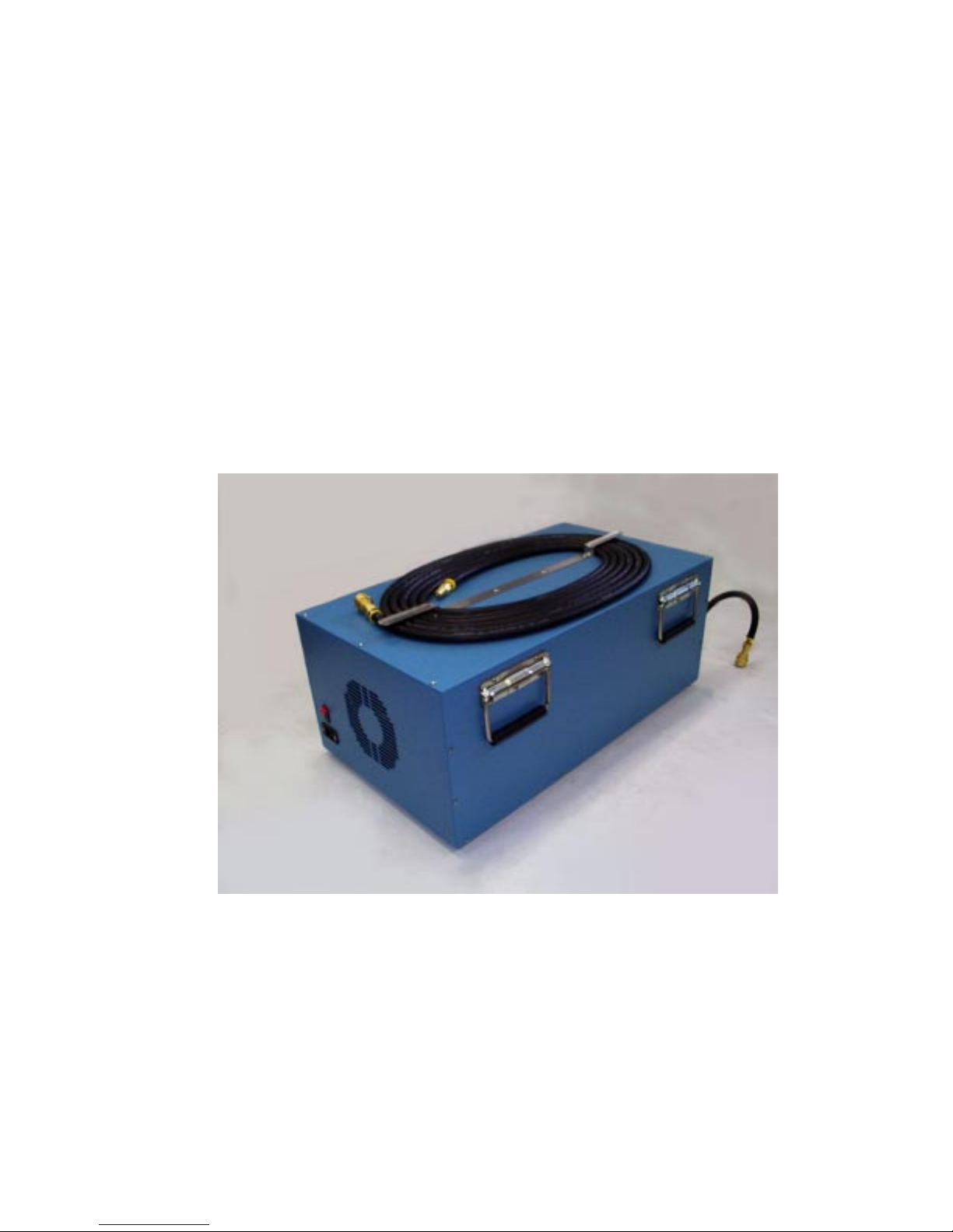
Model ACS-517B
Air Compressor System
Thunder Scientific Corporation
623 Wyoming Blvd. S.E. ◆ Albuquerque, New Mexico 87123-3198
Ordering: (800) 872.7728 ◆ Tel: (505) 265.8701 ◆ FAX: (505) 266.6203
www.thunderscientific.com
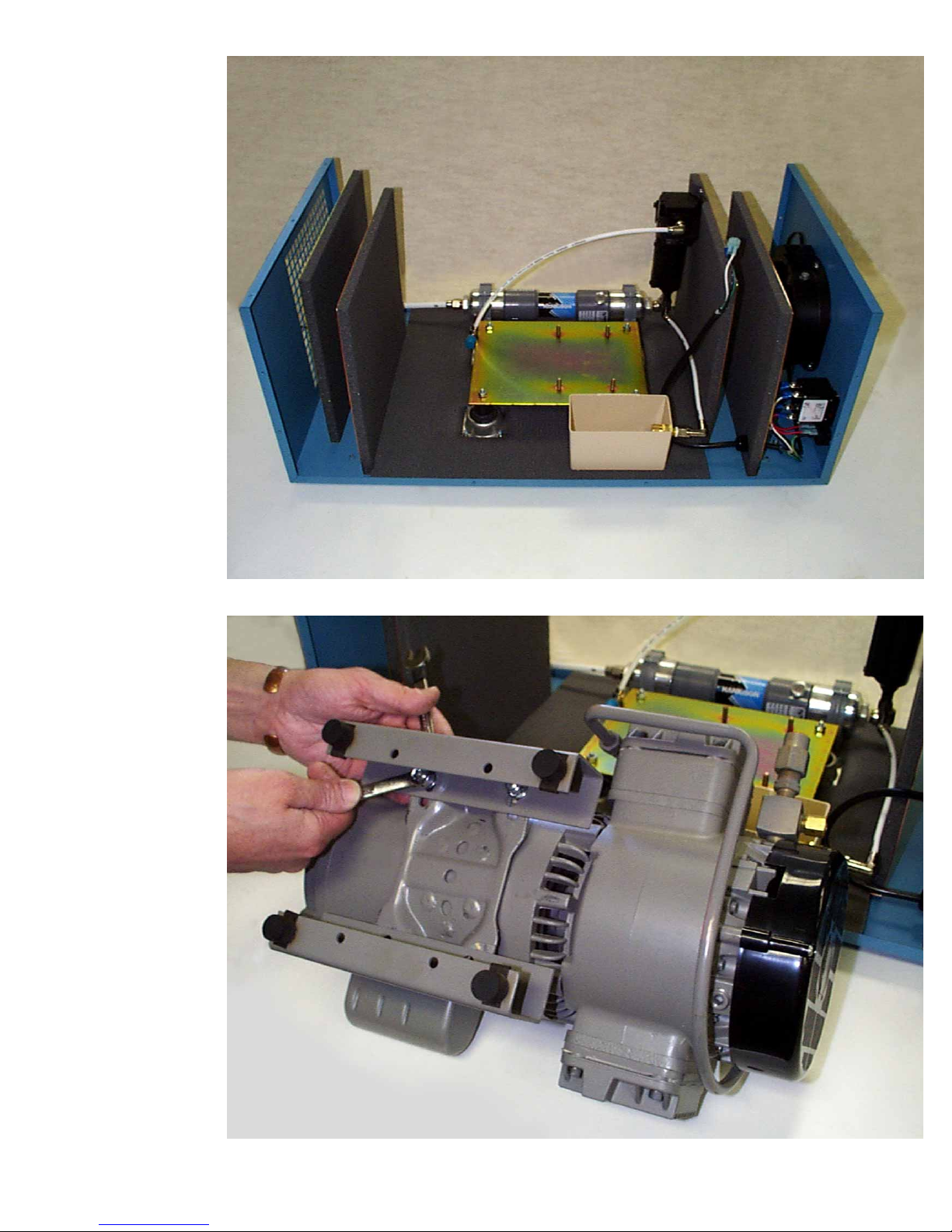
1. Remove the cover of the air compressor sound enclosure.
2. Remove the existing support brackets/feet from compressor unit.

3. Next remove the electrical cable cover and the compressor power cable. BE SURE UNIT IS UNPLUGGED.
Ground wire
LOW VOLTAGE
YEL/BLK
RED
BROWN
ORANGE
BLACK
WHITE
YELLOW
HIGH VOLTAGE
YEL/BLK
LINE
1
LINE
BROWN
RED
ORANGE
WHITE
BLACK
YELLOW
4
5
6
LINE
1
3
4
5
LINE
6
TO REVERSE,
INTERCHANGE
RED AND BLACK LEADS
ON HIGH VOLTAGE UNIT.
Figure 1
4. Install the ground wire, see Figure 1

PIN 1
Black wire
PIN 3
PIN 4
PIN 5
PIN 6
FIGURE 2
5. Connect the black wire to pin 1, see Figure 2.
White wire
6. Connect the white wire to pin 6, see Figure 2.

7. Replace the electrical cable cover on compressor unit.
8. Place the compressor as shown on the compressor mounting plate with studs through slots. Remove the round
black muffler from the compressor and save for step 17.

9. Slide the compressor towards the over flow drain box until it meets the end of the slot.
10. Add the hardware provided to all four studs, starting with the washer, then lock washer, and then the nut.

11. Remove the brass quick connect and elbow from the compressor unit.
12. Remove the nickel plated elbow by compressing the sleeve at the tube end of fitting and pull tubing out.

13. Screw nickel plated elbow into compressor and align elbow fitting at approximate angle as shown.
14. Reinsert Impolene tubing into nickel plated elbow and push firmly into place, then pull tube to see if snug.

CUT THE HOLE HERE
15. Cut a slit or hole in the foam insulation for the hose to pass through, then slide the insulation over the
compressor fan shrouding as shown above.
16. Apply silicone between fan shroud and insulation with silicone syringe (provided).

17. Insert the elbow (provided) where the muffler was removed from step 8. Then slide the black rubber hose
(provided) through the hole in the foam and the hole in the baffle panel.
18. Screw in the muffler into the rubber hose.

19. Slide the brass flare fitting of the rubber hose on to the threads of the elbow.
20. Tighten down the brass flare fitting.

21. Now replace compressor box cover with screws (22) provided and place in 2500 cart with hose side in line
with air tank and connect hose as shown above. Unit is now ready for use with your 2500.
PA RTS PROVIDED
1. Air Compressor System
2. 50 feet of air hose.
3. Silicone sealant
4. (4) each of washers, lockwashers, and nuts.
5. Compressor fan shroud insulation foam.
6. Black rubber hose with flare fitting.
7. 90° elbow.
 Loading...