

Page 1
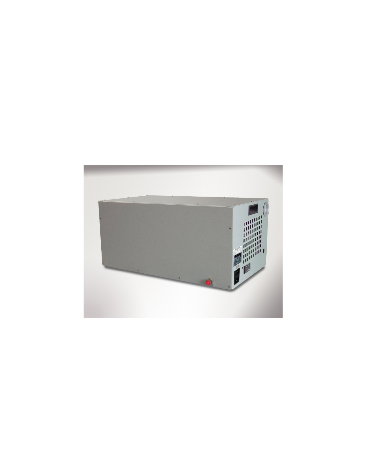
®
Operation and Maintenance Manual
for the
ACS1210
Air Compressor System
Thunder Scientific Corporation
623 Wyoming Blvd. SE Albuquerque, New Mexico 87123-3198
Ordering: (800) 872.7728
Copyright © 2020 by Thunder Scientific Corporation, All Rights Reserved
Tel: (505) 265.8701 FAX: (505) 266.6203
www.thunderscientific.com
Page 2

MADE IN USA
ACS1210 Operation and Maintenance Manual
Document Edition – 005 June 10, 2020
THUNDER SCIENTIFIC® is the registered trademark of Thunder Scientific Corporation.
All the information provided in this document is correct and true at the time of publication.
Thunder Scientific Corporation reserves the right to change any technical data without notice.
Page 3

TABLE OF CONTENTS
1 INTRODUCTION ............................................................................................. 2
2 SPECIFICATIONS and ENVIRONMENTAL CONDITIONS ............................ 2
2.1 Specifications ......................................................................................... 2
2.2 Environmental Conditions ...................................................................... 2
2.3 Warranty ................................................................................................ 2
3 SAFETY GUIDELINES .................................................................................... 3
4 INSTALLATION ............................................................................................... 3
4.1 Unpacking .............................................................................................. 3
4.2 Location ................................................................................................. 3
4.3 Hose Installation .................................................................................... 4
4.4 Power ..................................................................................................... 4
4.4.1 Extension Cord ...................................................................................... 4
5 COMPONENTS and CONTROLS ................................................................... 4
5.1 Power Switch ......................................................................................... 4
5.2 Hour Meter ............................................................................................. 4
5.3 Outlet Pressure Regulator ..................................................................... 4
5.4 Outlet Pressure Gauge .......................................................................... 4
5.5 Air Compressor ...................................................................................... 5
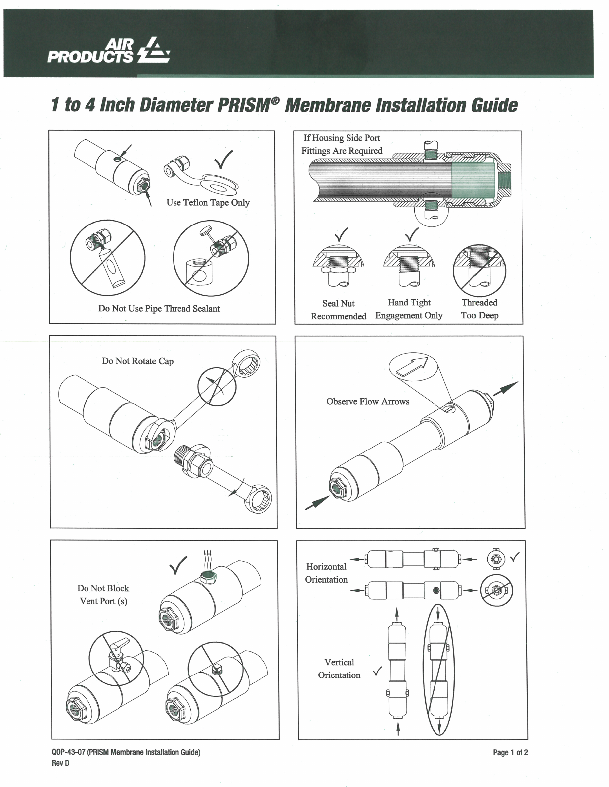
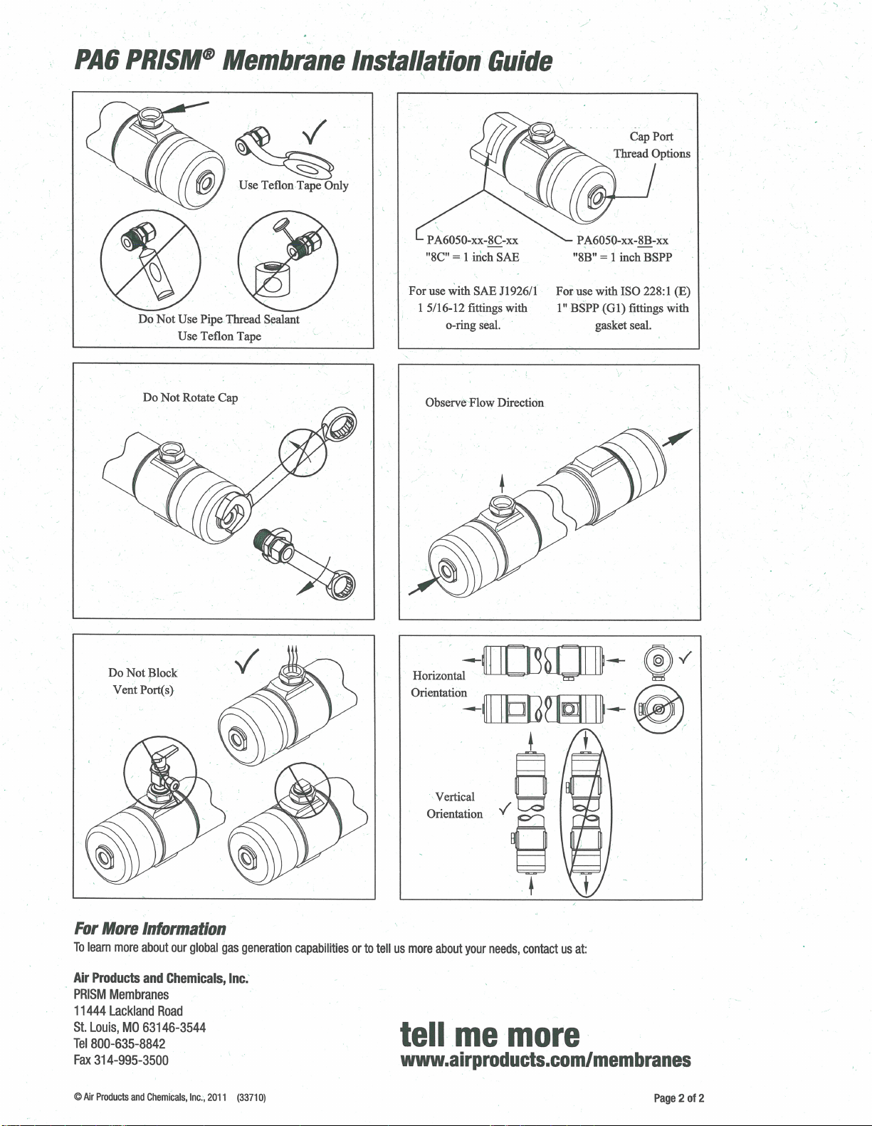
5.6 Membrane Air Dryer .............................................................................. 5
5.7 Safety Valve ........................................................................................... 5
5.8 Dimensional Drawing ............................................................................. 5
5.9 Component Locations ............................................................................ 6
6 GENERAL OPERATION ................................................................................. 7
6.1 Set-up .................................................................................................... 7
6.2 Pressure Adjustment ............................................................................. 7
6.3 Shut-down .............................................................................................. 7
7 INSPECTION and MAINTENANCE ................................................................ 7
7.1 Recommended Maintenance Schedule ................................................. 7
7.2 Filter Inspection and Replacement ........................................................ 7
7.3 Storage Procedures ............................................................................... 8
7.4 Service Kit .............................................................................................. 8
7.5 Heat Limit Switch ................................................................................... 9
8 SCHEMATICS ................................................................................................. 9
8.1 Pneumatic Schematic ............................................................................ 9
8.2 Electrical Schematic ............................................................................ 10
9 TROUBLESHOOTING GUIDE ...................................................................... 12
10 PARTS LIST .................................................................................................. 12
Thunder Scientific Corporation ACS 1210 Air Compressor System 1-1
Document Number: ACS1210.doc - Edition 05 - June 2020
Page 4

1 INTRODUCTION
The ACS1210 Oil-Less Compressed Air System is designed to be used as the air supply
for a Thunder Scientific Model 1200 humidity generator. The ACS1210 consists of a
vibration isolated oil-less piston compressor, membrane style air dryer, and output
regulator, all incorporated into a sound muffling cabinet. The ACS1210 is ideal for
laboratory use because of its high-pressure capability, 100% duty cycle capability, low
sound level of less than 70 decibels, and long service life.
2 SPECIFICATIONS and ENVIRONMENTAL CONDITIONS
2.1 Specifications
Voltage/Frequency 60Hz: ........................................................ 100-120VAC 50/60Hz, 10A
Voltage/Frequency 50Hz: ........................................................ 220-240VAC 50/60Hz, 6.3A
Pressure Rating (MAWP): .................................................................................... 165 psiG
Pressure Dew Point ............................................................ approximately 0 °C at 165 psiG
Duty Cycle: ................................................................................................................. 100%
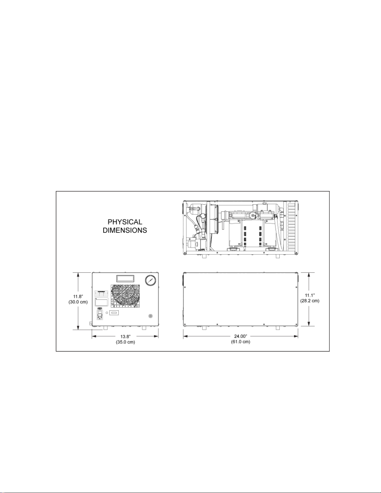
Physical Dimensions: ...................... 24.0 w" x 13.8 d" x 11.8 h" (61 cm x 35 cm x 30 cm)
Dry Weight: ............................................................................................ 48.2 lbs.(21.89 kg)
2.2 Environmental Conditions
Operating Temperature: .................................................................................... 15 to 30 °C
Storage Temperature: ...................................................................................... > 0 to 50 °C
Humidity: .................................................................................... 5 to 90% Non-condensing
2.3 Warranty
Thunder Scientific Corporation (TSC) warrants this product to be free of defects in
material and workmanship under normal use and service when operated within the
specified design limitations for a period of 90 days from date of shipment or 2000
operating hours, whichever comes first. TSC's obligation under this warranty shall be
limited to the following: the Product is returned to TSC with transportation charges
prepaid and that TSC's examination reveals the Product to be defective, TSC, at its
option, shall repair or replace at TSC's plant, any part or parts of the Product which is or
are defective. This warranty shall not apply to any Product that has become damaged or
inoperative because of ordinary wear, misuse, cold, heat, rain, excessive humidity, freeze
damage, use of improper chemicals, negligence, accident, failure to operate the product
in accordance with the instructions provided in the Owners Manual(s) supplied with the
product, improper maintenance, the use of accessories or attachments not recommended
by TSC or unauthorized repair or alterations.
THIS WARRANTY IS EXCLUSIVE AND IN LIEU OF ANY WARRANTY OF
MERCHANTABILITY, FITNESS FOR A PARTICULAR PURPOSE OR ANY OTHER
WARRANTY, WHETHER EXPRESS OR IMPLIED, AND ALL OTHER LIABILITIES AND
OBLIGATIONS ON THE PART OF TSC; TSC SHALL NOT BE LIABLE FOR ANY
INCIDENTAL, INDIRECT OR CONSEQUENTIAL LOSS, DAMAGE, OR EXPENSE
THAT MAY RESULT FROM ANY DEFECT, FAILURE OR MALFUNCTION OF THE
PRODUCT.
All warranties: express or implied, with respect to any device or component not
manufactured by TSC but incorporated into its Product are the responsibility of the
original manufacturer and shall not affect or apply to TSC.
Thunder Scientific Corporation ACS 1210 Air Compressor System 1-2
Document Number: ACS1210.doc - Edition 05 - June 2020
Page 5

3 SAFETY GUIDELINES
All compressed gases, including air, can be dangerous. Know and follow all safety rules
when using compressed air and especially when disconnecting and venting compressed
air lines.
Always operate the ACS1210 system in a clean, dry, well ventilated area, free of
combustible materials, or solvent vapors. Operate the ACS1210 in an open area at least
12 inches away from any wall or obstruction that would restrict the flow of fresh air to the
ventilation openings. Restricting any of the ACS1210 housing openings will cause
serious overheating leading to probable failure or possible fire.
Your ACS1210 system is powered by electricity. Like any other electrically powered
device, if not used properly it may cause electric shock. Never operate in wet conditions
and never operate with cover removed. Failure to provide adequate grounding could
result in serious injury or death from electrocution. Make certain that the electrical circuit
to which the ACS1210 is connected provides proper electrical grounding, correct voltage
and adequate fuse protection.
Attempting to operate the ACS1210 with damaged or missing parts or attempting to
repair the ACS1210 with protective cover removed can expose you to moving parts and
can result in serious injury. Any repair required should be performed by authorized
personnel. Repairs attempted by unqualified personnel can result in serious injury or
death by electrocution.
The compressed air directly from the ACS1210 is not safe for breathing and should never
be used to supply air for human consumption. The dried air from a membrane dryer will
contain less oxygen than normal air and under some conditions the dried air will not meet
breathing air standards for oxygen content. The air stream may also contain carbon
monoxide, toxic vapors, or solid particles. Breathing these contaminants can cause
serious injury or death.
This ACS1210 can fall from a table or workbench causing damage to the compressor and
could result in serious injury. Always operate the ACS1210 in a stable secure position to
prevent accidental movement of the unit.
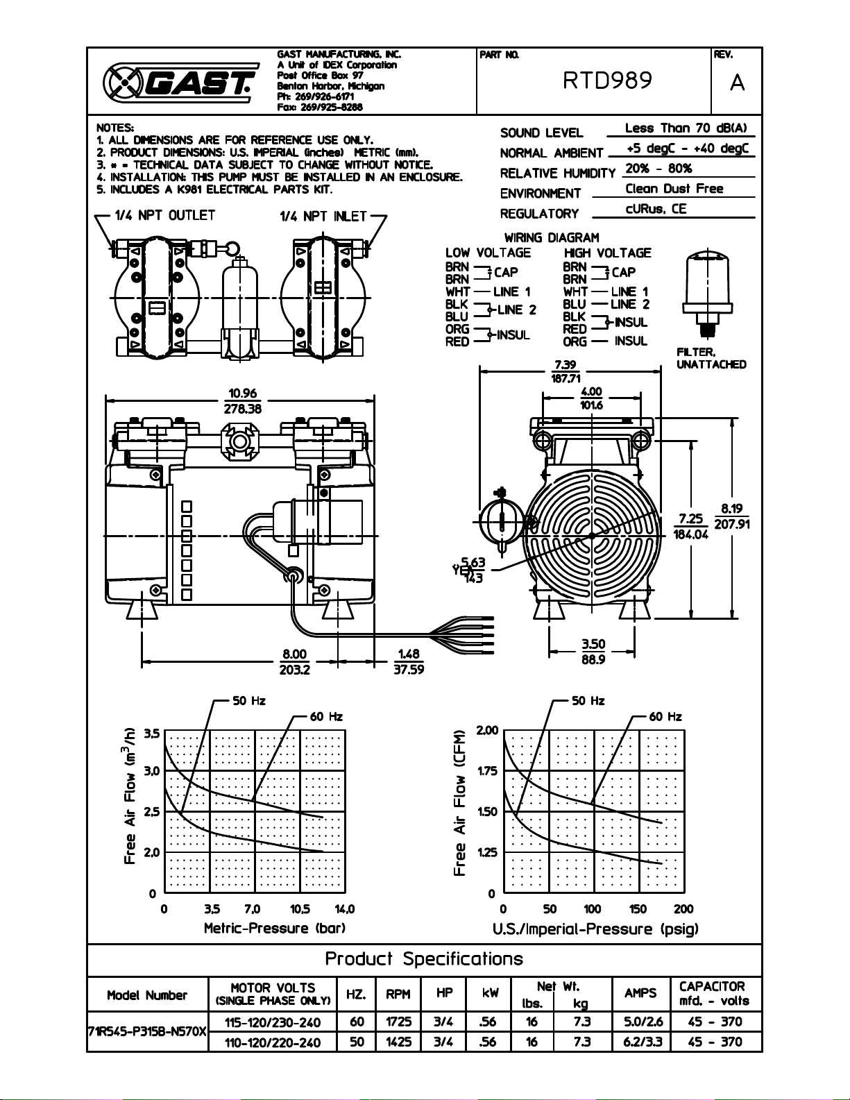
Refer to attached 71R Series Rocking Piston Oil-Less Pump Operating and Maintenance
Manual for additional specifications, service instructions, safety guidelines, hazard and
warning information.
4 INSTALLATION
4.1 Unpacking
Unpack the ACS1210 carefully and inspect it for any damage that may have occurred
during shipment. If there is shipping damage, notify the carrier immediately. Verify that
the power cord, air hose, and manual are present. If possible, save shipping container
for future use.
4.2 Location
Locate the ACS1210 on the 1200 utility cart or in a clean, dry and well-ventilated area. If
located remotely the system should be located at least 12 inches away from the wall or
other obstructions that will restrict the flow of air to the ventilation openings. The
compressor enclosure is designed to allow for proper cooling; therefore, ventilation
openings must remain unrestricted to maintain proper operating temperature.
Thunder Scientific Corporation ACS 1210 Air Compressor System 1-3
Document Number: ACS1210.doc - Edition 05 - June 2020
Page 6

4.3 Hose Assembly
Apply Teflon tape (1 thread back from end of fitting) to hose fitting and assemble hose
fitting to air outlet of ACS1210 using appropriate wrenches. Connect hose to fitting.
Connect other end of hose to the 1200 humidity generator.
Important: The hex fittings on the air outlet of the ACS1210 and the 1200 humidity
generator MUST be held in place with a wrench when tightening the fitting and hose.
4.4 Power
The ACS1210 is equipped with a power receptacle and cord having a grounding wire with
an appropriate grounding plug. The plug must be used with an outlet that has the same
configuration as the grounded plug and has been installed and grounded in accordance
with all local codes and ordinances.
Power of the appropriate voltage, frequency, and current capacity is applied via power
cord to the ACS1210 power receptacle.
4.4.1 Extension Cord
If an extension cord must be used, be sure it is a 3-wire extension cord that has a 3-blade
grounding plug, and a 3-slot receptacle that will accept the plug on the ACS1210 and is
14 gauge or larger and no longer than 50 feet.
5 COMPONENTS and CONTROLS
5.1 Power Switch
The Power Entry Module (PEM) allows power to be turned on or off at this location
independent from the 1200 generator. The Power Entry Module allows insertion of the
removable power cord, houses the On/Off power switch, and also houses the 10 amp
time-delay fuse (FS1).
5.2 Hour Meter
The Hour Meter (HM1) tracks total run time of the ACS1210 air compressing system.
5.3 Outlet Pressure Regulator
The Output Pressure Regulator (REG) controls the pressure available at the ACS1210
outlet which is indicated on the pressure gauge located on the left side of the system.
Turn the 9/32” (7mm) adjustment shaft clockwise to increase pressure and
counterclockwise to decrease pressure.
Note: Pressures higher than 165 psi should be avoided. Higher pressures will be
indicated by the "popping off" of the compressor safety valve.
Note: Adjustment may be necessary after one hour of run time to keep the indicated
pressure at 165 psi.
5.4 Outlet Pressure Gauge
Note: The Outlet Pressure Gauge (G1) indicates the regulated pressure available at the
outlet of the ACS1210 air compressing system. This pressure is controlled by the outlet
pressure regulator.
Thunder Scientific Corporation ACS 1210 Air Compressor System 1-4
Document Number: ACS1210.doc - Edition 05 - June 2020
Page 7
5.5 Air Compressor
The Oil-less Air Compressor (COMP) provides a maximum pressure of 165 psiG at a flow rate of
20 liters per minute or less.
5.6 Membrane Compressed Air Dryer
The Membrane Compressed Air Dryer (AD1) is located after the air compressors and is
specifically designed to remove water vapor from the compressed air stream. Typical pressure
dew points of 0 °C or less are maintained.
5.7 Safety Valve
The Safety Valve (mounted on compressor) protects the system against over pressure. Over
pressure is indicated by the "popping off" sound of the safety valve.
5.8 Dimensional Drawing
Thunder Scientific Corporation ACS 1210 Air Compressor System 1-5
Document Number: ACS1210.doc - Edition 05 - June 2020
Page 8
2
1
Regulator
Adjustment
3 4 5 6 8 7 10
9
Time Delay
Fuse Location
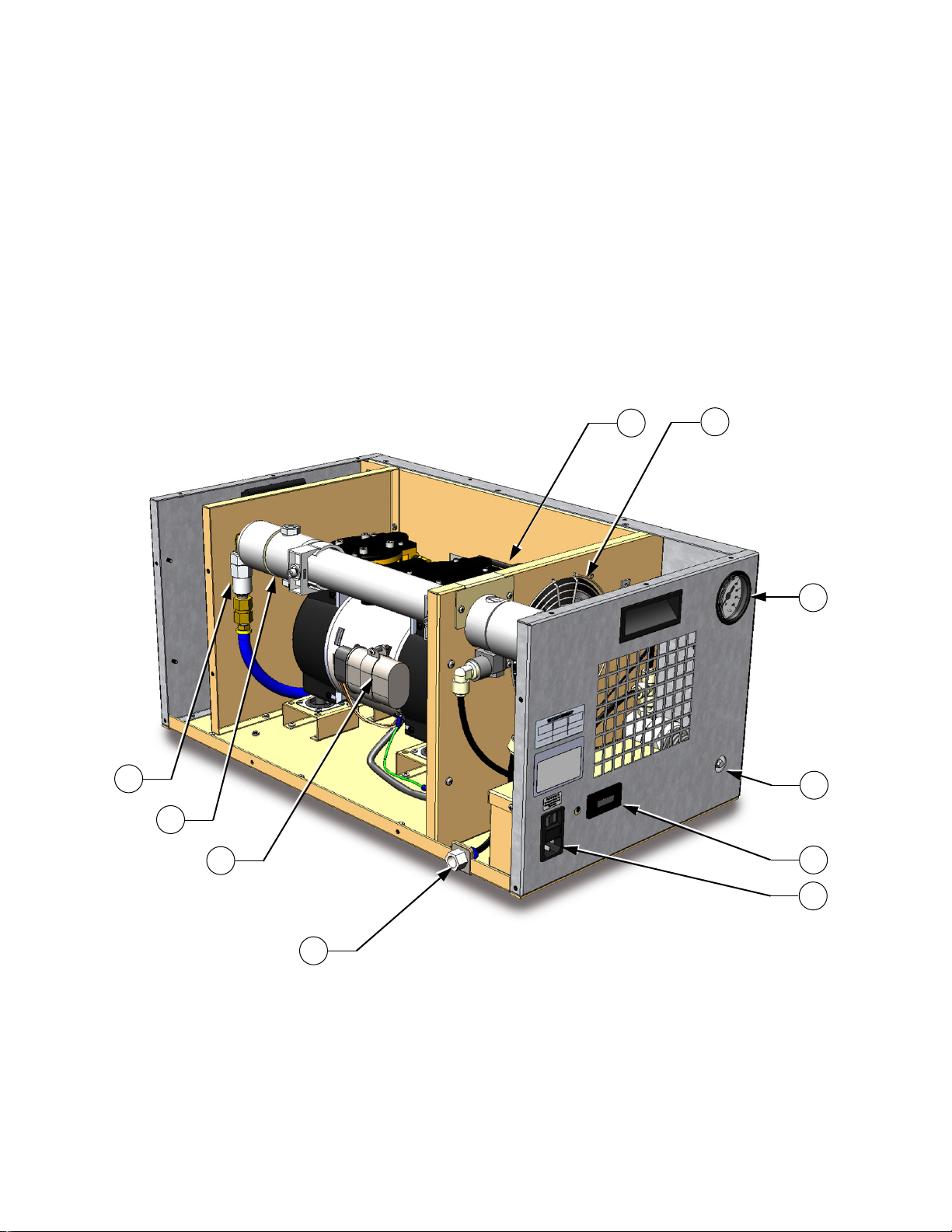
5.9 Component Locations
ITEM DESCRIPTION ITEM DESCRIPTION
1. Power Entry Module (PEM) 8. Air Compressor (COMP)
2. Hour Meter (HM1) 9. Air Intake Filter (F1)
3. Pressure Gauge (G1) 10. Air Dryer (AD1)
4. Regulator (REG) 11. Heat Limit Switch (HLS) On Page 9
5. Air Outlet 12. Solenoid Valve (SOL1) On Page 9
6. Particulate Filter (LF1)
7. Circulation Fan (CF1)
Rear View
Thunder Scientific Corporation ACS 1210 Air Compressor System 1-6
Document Number: ACS1210.doc - Edition 05 - June 2020
Page 9

6 GENERAL OPERATION
6.1 Start-up
Be sure the "Hose Installation" of paragraph 4.3 has been completed before proceeding.
Insert the power cord into the ACS1210 power receptacle. With the ACS1210 power
switch in the off position, plug the power cord into an AC mains outlet of the appropriate
voltage, frequency, and current capacity as indicated by the equipment label.
Apply power to the ACS1210 using the On/Off power switch. The compressor will start
and the pressure gauge will indicate approximately 165 psiG.
6.2 Pressure Adjustment
If pressure adjustment is required adjust the output pressure to 165 psiG, during no-flow
conditions, by turning the 9/32” (7mm) adjustment shaft on the regulator clockwise to
increase pressure and counterclockwise to decrease pressure.
6.3 Shut-down
Disconnect power to the ACS1210 using the On/Off power switch.
Important: All pressure MUST
be vented before disconnecting the air supply
hose or personal injury may result.
7 INSPECTION and MAINTENANCE
7.1 Recommended Maintenance Schedule
Periodic
Hours
Maintenance 100% Duty Cycle
Initial Inlet Filter Inspection 1
st 500
To establish service period
Minor Service Kit 1,500
Major Pump Rebuild or
Replacement 3,000
7.2 Filter Inspection
The Intake Filters require periodic inspection. Initial inspection is suggested at 500
hours; then user should determine the frequency thereafter. Most problems can be
prevented by keeping the intake filters clean. A dirty intake filter will decrease pump
performance and can decrease pump life.
Warning: Disconnect power and be sure all pressure has
been vented before service!
Thunder Scientific Corporation ACS 1210 Air Compressor System 1-7
Document Number: ACS1210.doc - Edition 05 - June 2020
Page 10
1. Intake
Filter (F1)
a. Remove the cover by pushing in and turning clockwise.
b. Clean paper/felt filter using air or vacuum.
c. Replace cover by pushing in and turning counterclockwise.
lean or replace element at 3,000 hours.
C
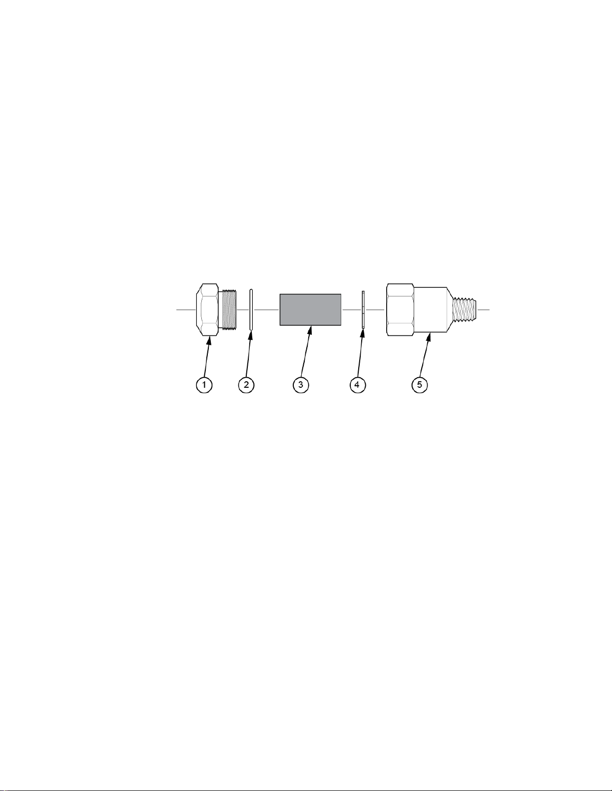
articulate a. Remove the filter by using a backup wrench on inlet elbow.
2. P
Filter (LF1) b. Unscrew the adapter (1) by turning counterclockwise.
c. Remove filter (3) and clean with water and blow dry or replace.
d. Inspect bowl (4 & 5) and seal (2). If dirty, clean by wipi
he bowl with a soft dry cloth.
t
e. Insure seal is clean and in place then re-install filter and
rotate the adapter clockwise until snug.
f. Re-install adapter using a backup wrench on inlet elbow
turning clockwise.
ng
P
articulate Filter (LF1)
7.
3 Storage Procedures
P
roper shutdown procedures must be followed to prevent pump damage. Failure to do
so may result in premature pump failure. The non-lubricated compressor is constructed
of ferrous metals and/or aluminum which are treated for corrosion protection but are still
subject to possible rust and corrosion when pumping condensable vapors such as water.
F
ollow the steps below to assure correct shutdown and storage between uses:
1. NEVER oil this non-lubricated compressor as damage will result.
2. For long term storage of the ACS1210, disconnect the air hose at outlet and
apply power allowing the compressor to run "open" for at least five minutes.
After five minutes remove power and plug/cap outlet to prevent contaminants
from entering. The ACS1210 is now ready for storage.
7.4 Service Kit
efer to attached 71R Series Rocking Piston Oil-Less Pump Operating and Maintenance
R
Manual for parts and procedures.
Thunder Scientific Corporation ACS 1210 Air Compressor System 1-8
Document Number: ACS1210.doc - Edition 05 - June 2020
Page 11
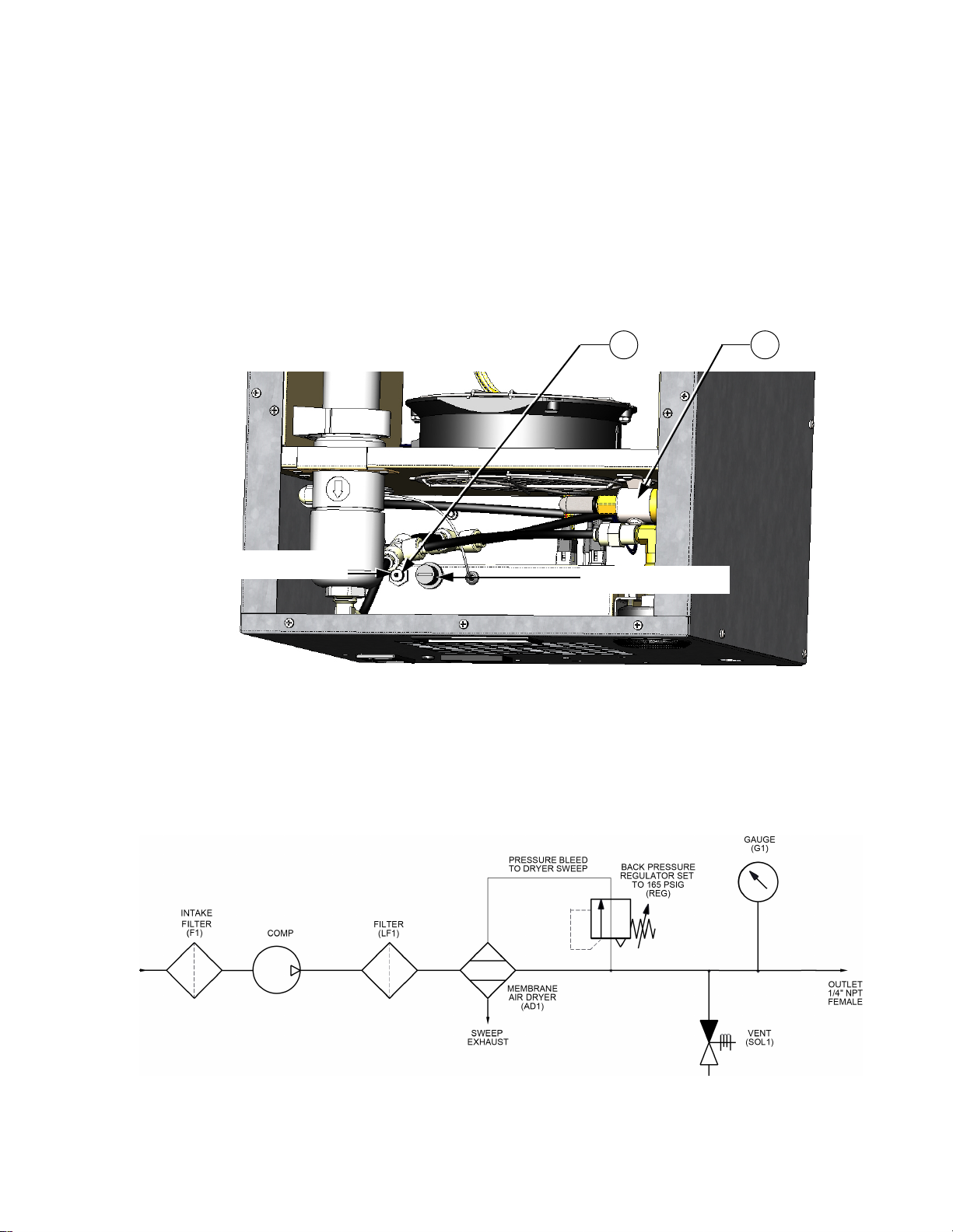
7.5 Heat Limit Switch
11
12
Black Slotted Cap
Heat Limit Switch
The non-recycling heat limit switch (HLS) trips at a predetermined set point shutting down
the circuit until reactivated. This switch is tripped in the event of elevated temperature
above the maximum operating temperature.
To reactivate limit switch
a. Remove ACS1210 top access cover.
b. Locate and remove the black slotted limit switch cap.
c. Press the reset button (under black cap).
d. Replace black slotted cap.
e. Replace the ACS1210 access cover.
Top View
8 SCHEMATICS
8.1 Pneumatic Schematic
Figure 1-1
Thunder Scientific Corporation ACS 1210 Air Compressor System 1-9
Document Number: ACS1210.doc - Edition 05 - June 2020
Page 12
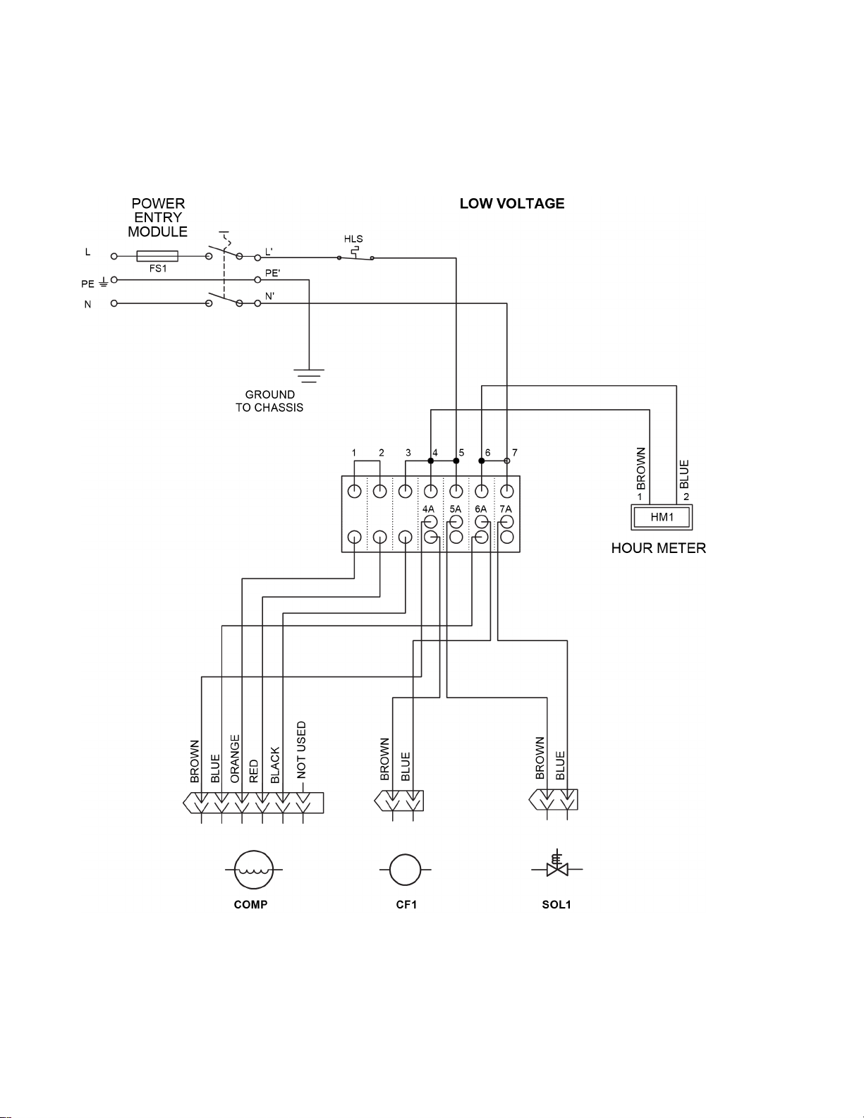
8.2 Electrical Schematics
110 VAC
Figure 1-2
Thunder Scientific Corporation ACS 1210 Air Compressor System 1-10
Document Number: ACS1210.doc - Edition 05 - June 2020
Page 13
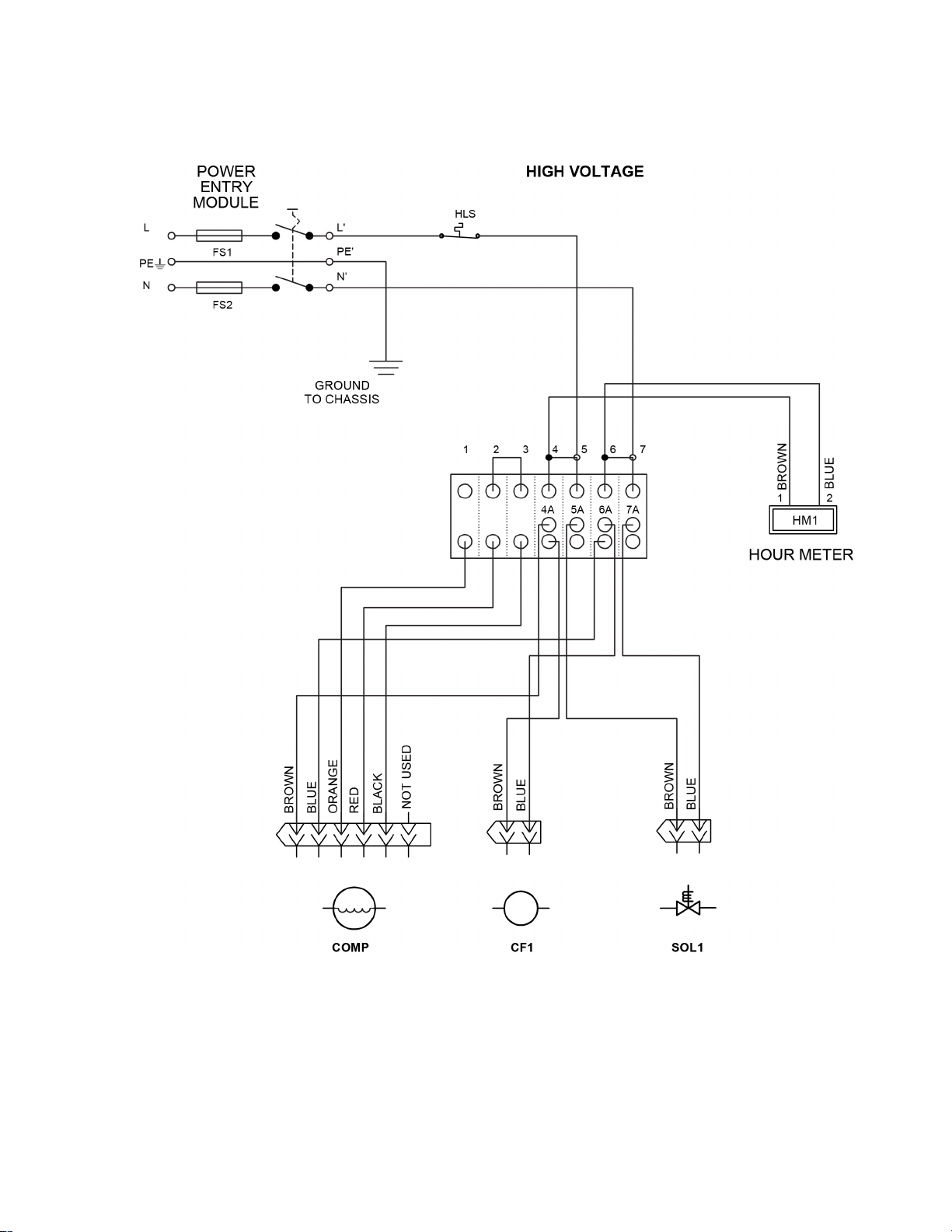
220 VAC
Figure 1-3
Thunder Scientific Corporation ACS 1210 Air Compressor System 1-11
Document Number: ACS1210.doc - Edition 05 - June 2020
Page 14

9 TROUBLESHOOTING GUIDE
Possible Reason No / Low High Excessive Over Won't
Pressure Pressure Noise Heating Start
Dirty Intake Filter (F1) X
Dirty Particulate Filter (LF1) X
Hose Leak X
Regulator Adjustment X X X
Worn or Damaged Compressor X X X
Worn or Damaged Fan X X
Safety Valve "Popping Off" X X
Plugged Pressure Line X X
Low Voltage X X
Blocked Ventilation Opening X X X X
High Outlet Pressure X
Overheating X X X X X
Heat Limit Switch Tripped X X
10 PARTS LIST
Find # Qty Description Part Number
PEM 1 Power Entry Module PEM-1205
* PEM-1105
FS1 1 Fuse, 10 Amp Time Delay GMC10
FS2 2 Fuse, 6.3 Amp Time Delay * GDC6.3
HM1 1 Hour Meter HRMETERACS
COMP 1 Compressor, 100-120VAC 50/60Hz ACS2022
Compressor, 220-240VAC 50/60Hz * ACS2022
G1 1 Gauge, Pressure G1X510
REG 1 Regulator, Back Pressure JBPREG
AD1 1 Air Dryer, Membrane MD1015
CF1 1 Fan, Circulation MR2B3
* MR77B3
F1 1 Element, Air Intake Filter C85679
LF1 1 Filter, Particulate FRP-95-199
SOL1 1 Valve, Solenoid U147121-110
* U147121-220
HLS 1 Switch, Heat Limit CAP-MR-140-SS
* Asterisk Indicates High Voltage Parts
Thunder Scientific Corporation ACS 1210 Air Compressor System 1-12
Document Number: ACS1210.doc - Edition 05 - June 2020
Page 15

This Page Intentionally
Left Blank
Thunder Scientific Corporation ACS 1210 Air Compressor System 1-13
Document Number: ACS1210.doc - Edition 05 - June 2020
Page 16
71R & 72R SERIES
ROCKING PISTON OIL-LESS PUMPS
OPERATION & MAINTENANCE MANUAL
Product Use Criteria:
• Pump only clean, dry air.
• Operate at 32ºF - 104ºF (0ºC - 40ºC).
• Protect unit from dirt & moisture.
• Do not pump flammable or explosive gases or
use in an atmosphere that contains such gases.
• Protect all surrounding items from exhaust air. This
exhaust air can become very hot.
• Corrosive gases and particulate material will
damage unit. Water vapor, oil-based contaminants
or other liquids must be filtered out.
• Consult your Gast Distributor/Representative
before using at high altitudes.
• This pump is oil-less and requires NO lubrication.
Thank you for purchasing this Gast product. It is manufactured to the highest standards
using quality materials. Please follow all recommended maintenance, operational
and safety instructions and you will receive years of trouble free service.
www.gastmfg.com
ISO 9001 & 14001 CERTIFIED
®Registered Trademark/™Trademark of Gast Manufacturing Inc., Copyright ©2002 Gast Manufacturing Inc. All Rights Reserved.
PART NO. 70 - 6800 G495PL (REV-G)
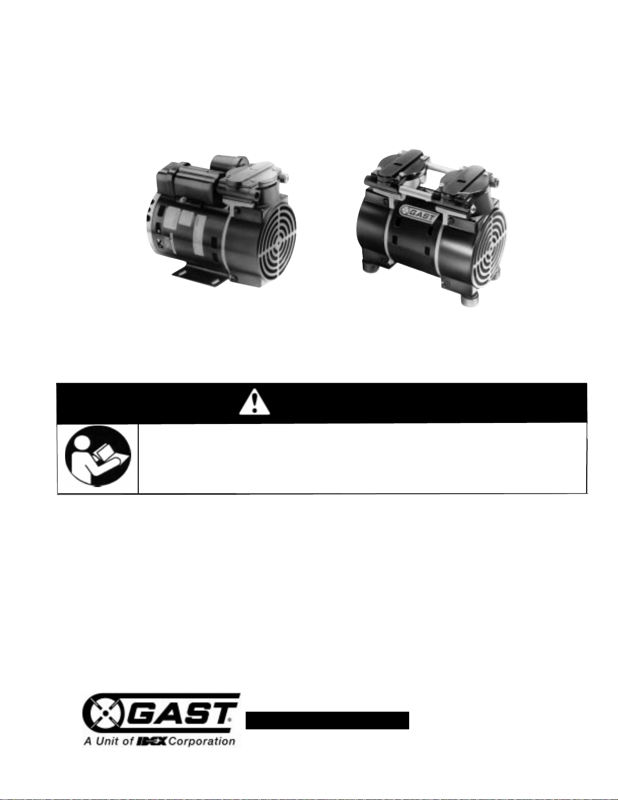
Single Cylinder Model Shown
Twin Cylinder Model Shown
WARNING
PLEASE READ THIS MANUAL COMPLETELY BEFORE INSTALLING AND USING
THIS PRODUCT. SAVE THIS MANUAL FOR FUTURE REFERENCE AND
KEEP IN THE VICINITY OF THE PRODUCT.
Page 17
Motor Control
It is your responsibility to contact a qualified
electrician and assure that the electrical installation
is adequate and in conformance with all national
and local codes and ordinances. The metal
capacitor must be grounded.
Determine the correct overload setting required to
protect the motor (see motor starter manufacturer’s
recommendations). Select fuses, motor protective
switches or thermal protective switches to provide
protection. Fuses act as short circuit protection for the
motor, not as protection against overload. Incoming line
fuses must be able to withstand the motor’s starting
current. Motor starters with thermal magnetic overload
or circuit breakers protect motor from overload or
reduced voltage conditions.
The wiring diagram supplied with the product provides
required electrical information. Check that power
source is correct to properly operate the dual-voltage
motors.
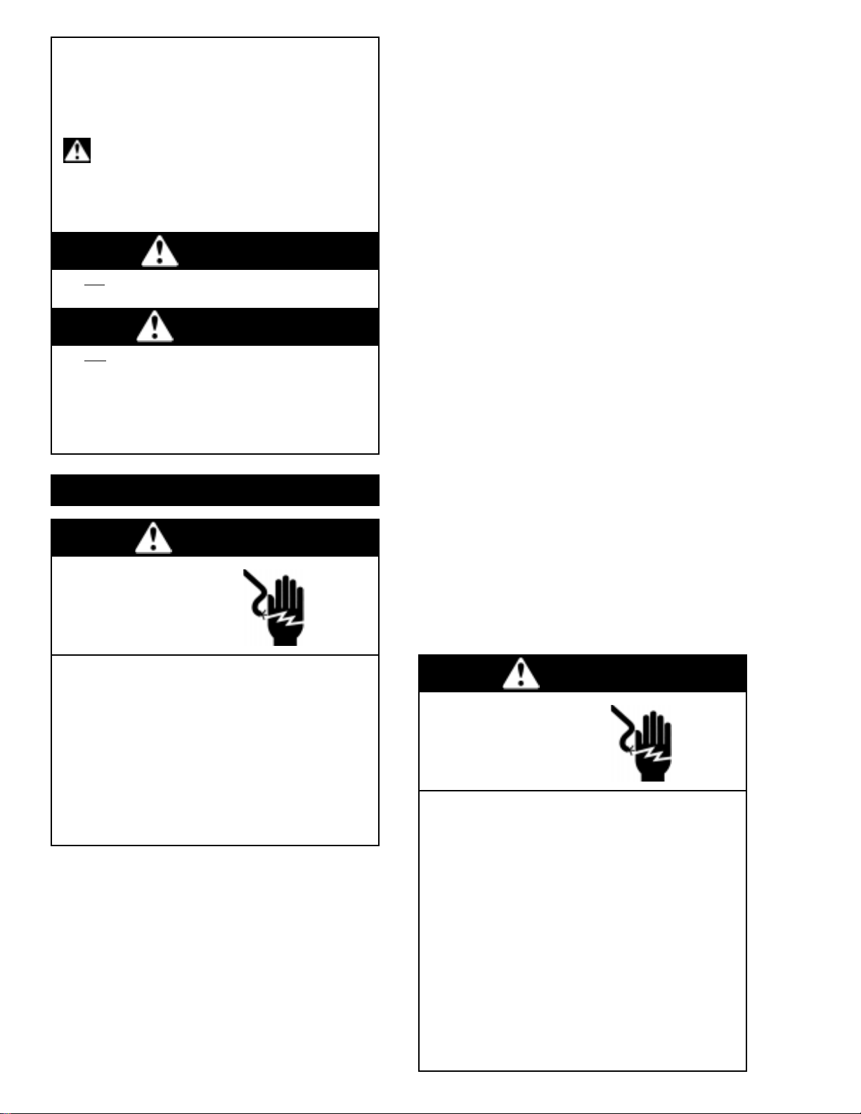
Your safety and the safety of others
is extremely important.
We have provided many important safety messages
in this manual and on your product. Always read
and obey all safety messages.
This is the safety alert symbol. This symbol
alerts you to hazards that can kill or hurt you and
others. The safety alert symbol and the words
“DANGER” and “WARNING” will precede all safety
messages. These words mean:
You will
be killed or seriously injured if you don’t
follow instructions.
You can be killed or seriously injured if you don’t
follow instructions.
All safety messages will identify the hazard, tell you
how to reduce the chance of injury, and tell you
what can happen if the safety instructions are not
followed.
Correct installation is your responsibility. Make sure
you have the proper installation conditions and that
installation clearances do not block air flow.
Blocking air flow over the product in any way can
cause the product to overheat.
Mounting
This product can be installed in any orientation.
Mounting the product to a stable, rigid operating surface
and using shock mounts will reduce noise and vibration.
INSTALLATION
Accessories
The product’s external intake and exhaust muffler will
provide adequate filtration in most applications. Check
filters periodically and replace when necessary. Consult
your Gast Distributor/Representative for additional filter
recommendations.
WARNING
DANGER
Plumbing
Remove plugs from the IN and OUT ports. Connect
with pipe and fittings that are the same size or larger
than the product’s threaded ports. Be sure to connect
the intake and exhaust plumbing to the correct inlet and
outlet ports. Ports will not support plumbing.
Install relief valves and gauges at inlet or outlet or both,
to monitor performance. Check valves may be required
to prevent back streaming through the pump.
Electrical Connection
WARNING
c
Electrical Shock Hazard
Disconnect electrical power at the circuit breaker
or fuse box before installing this product.
Install this product where it will not come into
contact with water or other liquids.
Install this product where it will be weather
protected.
Electrically ground this product.
Failure to follow these instructions can result in
death, fire or electrical shock.
WARNING
c
Electrical Shock Hazard
This product must be properly grounded.
Do not modify the plug provided. If it will not
fit the outlet, have the proper outlet installed
by a qualified electrician.
If repair or replacement of the cord or plug is
necessary,do not connect the grounding wire
to either flat blade terminal. The wire with
insulation that is green or green with yellow
stripes is the grounding wire.
Check the condition of the power supply wiring.
Do not permanently connect this product to
wiring that is not in good condition or is
inadequate for the requirements of this product.
Failure to follow these instructions can result in
death, fire or electrical shock.
Page 18
OPERATION
Model with a power supply cord:
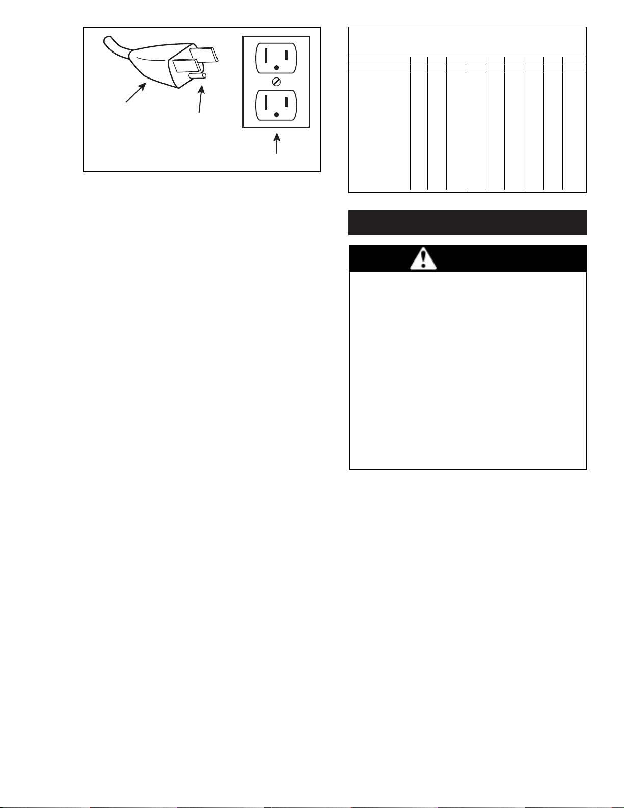
This product must be grounded. For either 120-volt or
220/240-volt circuits connect power supply cord
grounding plug to a matching grounded outlet. Do not
use an adapter. (See above diagram.)
Check with a qualified electrician or serviceman if
the grounding instructions are not completely
understood, or if you are not sure whether the
product is properly grounded. Do not modify the
plug provided. If it will not fit the outlet, have the
proper outlet installed by a qualified electrician.
In the event of an electrical short circuit, grounding
reduces the risk of electric shock by providing an
escape wire for the electric current. This product may
be equipped with a power supply cord having a
grounding wire with an appropriate grounding plug.
The plug must be plugged into an outlet that is properly
installed and grounded in accordance with all local
codes and ordinances.
Grounded Plug
Model that is permanently wired:
This product must be connected to a grounded,
metallic, permanent wiring system, or an equipment
grounding terminal or lead on the product.
Power supply wiring must conform to all required safety
codes and be installed by a qualified person. Check
that supply voltage agrees with that listed on product
nameplate.
Extension cords:
Use only a 3-wire extension cord that has a 3-blade
grounding plug. Connect extension cord plug to a
matching 3-slot receptacle. Do not use an adapter.
Make sure your extension cord is in good condition.
Check that the gage wire of the extension cord is the
correct size wire to carry the current this product will
draw.
An undersized cord is a potential fire hazard, and will
cause a drop in line voltage resulting in loss of power
causing the product to overheat. The following table
indicates the correct size cord for length required and
the ampere rating listed on the product nameplate. If in
doubt, use the next heavier gage cord. The smaller
the gage number, the heavier the wire gage.
Minimum gage for extension cords
Amps Volts Length of cord in feet
120v 25 50 100 150 200 250 300 400 500
240v 50 100 200 300 400 500 600 800 1000
0-2 18 18 18 16 16 14 14 12 12
2-3 18 18 16 14 14 12 12 10 10
3-4 18 18 16 14 12 12 10 10 8
4-5 18 18 14 12 12 10 10 8 8
5-6 18 16 14 12 10 10 8 8 8
6-8 18 16 12 10 10 8 6 6 6
8-10 18 14 12 10 88664
10-12 16 14 10 886644
12-14 16 12 10 866642
14-16 16 12 10 866442
16-18 14 12 8 864422
18-20 14 12 8 664422
Start Up
If motor fails to start or slows down significantly under
load, shut off and disconnect from power supply. Check
that the voltage is correct for motor and that motor is
turning in the proper direction. Check the plug, cord
and switch for damage. If so equipped, the thermal
protection switch has tripped, the motor can restart after
cooling.
It is your responsibility to operate this product at
recommended pressures or vacuum duties and
room ambient temperatures. Do not start against a
vacuum or pressure load.
Grounding Pin
120-volt grounded connectors
shown. 220/240-volt grounded
connectors will differ in shape.
Grounded Outlet
WARNING
Injury Hazard
Install proper safety guards as needed.
Keep fingers and objects away from openings and
rotating parts.
When provided, motor terminal covers must be in
place for safe operation.
Product surfaces become very hot during operation,
allow product surfaces to cool before handling.
Air stream from product may contain solid or liquid
material that can result in eye or skin damage,
wear proper eye protection.
Wear hearing protection. Sound level from motor
may exceed 70 dBA.
Failure to follow these instructions can result in
burns, eye injury or other serious injury.
Page 19
It is your responsibility to:
• Regularly inspect and make necessary repairs to
product in order to maintain proper operation.
• Make sure that pressure is released from product
before starting maintenance.
MAINTENANCE
c
Disconnect electrical power supply cord before
performing maintenance on this product.
If product is hard wired into system, disconnect
electrical power at the circuit breaker or fuse box
before performing maintenance on this product.
Failure to follow these instructions can result in
death, fire or electrical shock.
Electrical Shock Hazard
WARNING
Check that all external accessories such as relief
valves and gauges are attached to cover and are not
damaged before re-operating product.
Check intake and exhaust filters after first 500 hours of
operation. Clean filters and determine how frequently
filters should be checked during future operation. This
one procedure will help to assure the product’s
performance and service life.
SHUTDOWN PROCEDURES
It is your responsibility to follow proper shutdown
procedures to prevent product damage.
NEVER ADD OIL TO THIS OIL-LESS PUMP.
Proper shutdown procedures must be followed to
prevent pump damage. Failure to do so may result in
premature pump failure. Gast Manufacturing Rocking
Piston Oil-Less Pumps are constructed of ferrous
metals or aluminum which are subject to rust and
corrosion when pumping condensable vapors such as
water. Follow the steps below to assure correct storage
and shutdown between operating periods.
1. Disconnect plumbing.
2. Operate product for at least 5 minutes without
plumbing.
3. Run at maximum vacuum for 10 to 15 minutes.
4. Repeat step 2.
5. Disconnect power supply.
6. Plug open ports to prevent dirt or other
contaminants from entering product.
Gast will NOT guarantee field-rebuilt product
performance. For performance guarantee, the
product must be returned to a Gast Authorized
Service Facility.
Service Kit contents vary. Most contain gasket and filter
parts.
SERVICE KIT INSTALLATION
1. Remove filter cover.
2. Remove filters and felt (some filters are held
together with a snap fitting). Clean filters by
washing in a non-petroleum based solvent or soap
and water. After cleaning, dry with compressed air
to make sure all moisture is removed before
reinstalling filters.
3. Reinstall felt and filters.
4. Reinstall cover.
WARNING
Injury Hazard
Product surfaces become very hot during operation,
allow product surfaces to cool before handling.
Air stream from product may contain solid or liquid
material that can result in eye or skin damage,
wear proper eye protection.
Clean this product in a well ventilated area.
Failure to follow these instructions can result in
burns, eye injury or other serious injury.
WARNING
c
Electrical Shock Hazard
Disconnect electrical power supply cord before
installing Service Kit.
If product is hard wired into system, disconnect
electrical power at the circuit breaker or fuse box
before installing Service Kit.
Vent all air lines to release pressure or vacuum.
Failure to follow these instructions can result in
death, fire or electrical shock.
Page 20

1. Disconnect electrical power to pump.
2. Disconnect air supply and vent all air lines to
release pressure or vacuum.
3. Mark the orientation of the ports so cover will be
reinstalled correctly.
4. Remove screws from the head of the pump.
Remove the head of the pump.
5. Mark orientation of valve plate(s). Remove valve
plate(s).
6. Remove and discard old cups(s), retainer screws,
cylinder O-ring(s), head O-ring(s), valves and valve
retainers.
7. Install new cup(s) on rod(s) facing up.
8. Reinstall retainer plates.
9. Apply a thread locking compound (Loctite 222) to
retainer screws. Torque screws to 34-38 in. lbs.
10.Carefully install cylinder(s) over cup(s) at an angle to
avoid damaging cup(s).
11.Clean valve plates with water based solvent. Take
care to not scratch valve seats.
12.Install valves and valve retainers. Check that the
orientation with the ports is correct.
13.Apply a thread locking compound (Loctite 222) to
retainer screws. Torque screws to 10-13 in. lbs.
14.Install cylinder O-ring(s) in the bottom of valve
plate(s).
15.Check that the orientation of valve plate(s) with the
ports is correct.
16.Install head O-rings in the O-ring grooves on top of
valve plate.
17.Reinstall head over valve plate(s) checking that
orientation with ports is correct.
18.Torque screws to 50 in. lbs.
Check that all external accessories such as relief
valves and gauges are not damaged before
re-operating product.
If pump still does not produce proper vacuum or
pressure, send unit to a Gast Authorized Service Facility
for repair.
Gast finished products, when properly installed and operated under normal conditions of use, are warranted by Gast to
be free from defects in material and workmanship for a period of twelve (12) months from the date of purchase from
Gast or an authorized Gast Representative or Distributor. In order to obtain performance under this warranty, the buyer
must promptly (in no event later than thirty (30) days after discovery of the defect) give written notice of the defect to
Gast Manufacturing Incorporated, PO Box 97, Benton Harbor Michigan USA 49023-0097 or an authorized Service
Center (unless specifically agreed upon in writing signed by both parties or specified in writing as part of a Gast OEM
Quotation). Buyer is responsible for freight charges both to and from Gast in all cases.
This warranty does not apply to electric motors, electrical controls, and gasoline engines not supplied by Gast. Gast’s
warranties also do not extend to any goods or parts which have been subjected to misuse, lack of maintenance,
neglect, damage by accident or transit damage.
THIS EXPRESS WARRANTY EXCLUDES ALL OTHER WARRANTIES OR REPRESENTATIONS EXPRESSED OR
IMPLIED BY ANY LITERATURE, DATA, OR PERSON. GAST’S MAXIMUM LIABILITY UNDER THIS EXCLUSIVE
REMEDY SHALL NEVER EXCEED THE COST OF THE SUBJECT PRODUCT AND GAST RESERVES THE RIGHT,
AT ITS SOLE DISCRETION, TO REFUND THE PURCHASE PRICE IN LIEU OF REPAIR OR REPLACEMENT.
GAST WILL NOT BE RESPONSIBLE OR LIABLE FOR INDIRECT OR CONSEQUENTIAL DAMAGES OF ANY KIND,
however arising, including but not limited to those for use of any products, loss of time, inconvenience, lost profit, labor
charges, or other incidental or consequential damages with respect to persons, business, or property, whether as a
result of breach of warranty, negligence or otherwise. Notwithstanding any other provision of this warranty, BUYER’S
REMEDY AGAINST GAST FOR GOODS SUPPLIED OR FOR NON-DELIVERED GOODS OR FAILURE TO FURNISH
GOODS, WHETHER OR NOT BASED ON NEGLIGENCE, STRICT LIABILITY OR BREACH OF EXPRESS OR
IMPLIED WARRANTY IS LIMITED SOLELY, AT GAST’S OPTION, TO REPLACEMENT OF OR CURE OF SUCH
NONCONFORMING OR NON-DELIVERED GOODS OR RETURN OF THE PURCHASE PRICE FOR SUCH GOODS
AND IN NO EVENT SHALL EXCEED THE PRICE OR CHARGE FOR SUCH GOODS. GAST EXPRESSLY
DISCLAIMS ANY WARRANTY OF MERCHANTABILITY OR FITNESS FOR A PARTICULAR USE OR PURPOSE WITH
RESPECT TO THE GOODS SOLD. THERE ARE NO WARRANTIES WHICH EXTEND BEYOND THE DESCRIPTIONS
SET FORTH IN THIS WARRANTY, notwithstanding any knowledge of Gast regarding the use or uses intended to be
made of goods, proposed changes or additions to goods, or any assistance or suggestions that may have been made
by Gast personnel.
Unauthorized extensions of warranties by the customer shall remain the customer’s responsibility.
CUSTOMER IS RESPONSIBLE FOR DETERMINING THE SUITABILITY OF GAST PRODUCTS FOR CUSTOMER’S
USE OR RESALE, OR FOR INCORPORATING THEM INTO OBJECTS OR APPLICATIONS WHICH CUSTOMER
DESIGNS, ASSEMBLES, CONSTRUCTS OR MANUFACTURES.
This warranty can be modified only by authorized Gast personnel by signing a specific, written description of any
modifications.
WARRANTY
Page 21
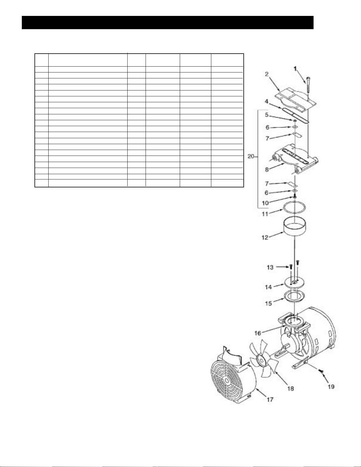
REF DESCRIPTION QTY 71R135-P001B 71R142-P001B 72R142-P001B
1 CAP SCREWS 4 BB570 BB570 BB570
2 HEAD 1 AT265G AT265G AT265
4 ∆ HEAD O-RING 1 AT258 AT258 AT258
5 HEX NUT 1 BC164 BC164 BC164
6 ∆ VALVE RETAINER 2 AF819A AF819A AF819A
7 ∆ LEAF VALVE 2 AF817 AF817 AF817
8 VALVE PLATE 1 AT631E AT631E AT281E
10 VALVE SCREW 1 BB330B BB330B BB330A
11 ∆ CYLINDER O-RING 1 AT256 AT256 AT276
12 ∆ CYLINDER 1 AT272 AT272 AT275
13 ∆ RETAINER SCREW 2 AT283 AT283 AT283
14 RETAINER PLATE 1 AT715 AT715 AT566A
15 ∆ PISTON CUP 1 AT329 AT329 AT280
16 ROD ASSEMBLY 1 AT526KZ AT526GZ AT527GZ
17 SHROUD 1 AT266 AT266 AT266
18 FAN 1 AT260A AT260A AT260A
19 SHROUD SCREW 4 AT261 AT261 AT261
20 VALVE PLATE ASSEMBLY 1 AT633K AT633K AT282K
*** FILTER 1 B300F B300F B300F
*** SERVICE KIT 1 K704 K704 K705
EXPLODED PRODUCT VIEW, PARTS & ORDERING INFORMATION
*** Item not shown.
∆ Denotes parts included in the Service Kit.
Parts listed are for stock models. For specific OEM models, please consult the factory.
When corresponding or ordering parts, please give complete model and serial numbers.
Page 22
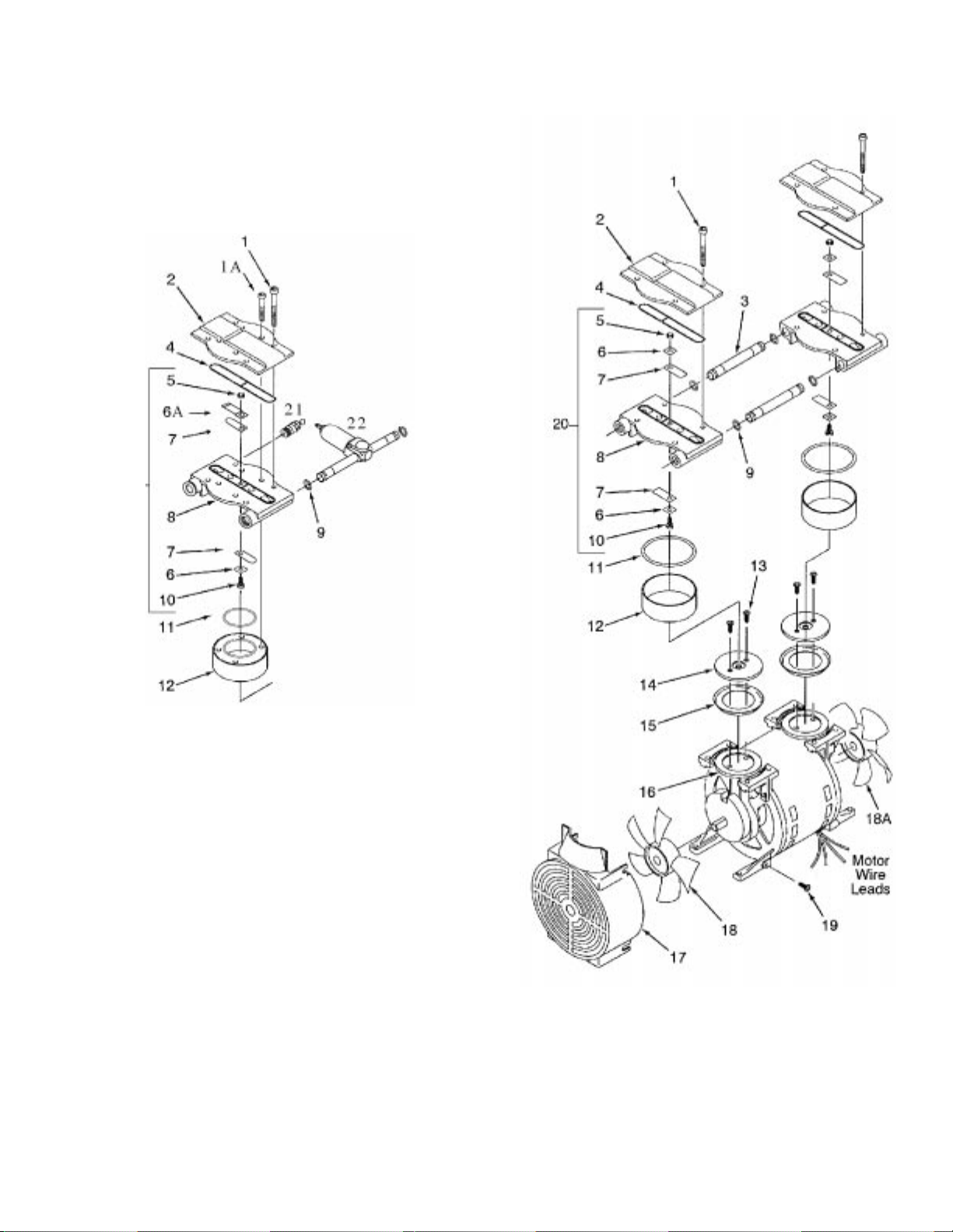
(FIG 1)
FOR MODELS 71R545-P315B
COVER/VALVE PLATE ASSM. SHOWN
SEPARATELY TO SHOW HIGH
PRESSURE END OF UNIT
Page 23
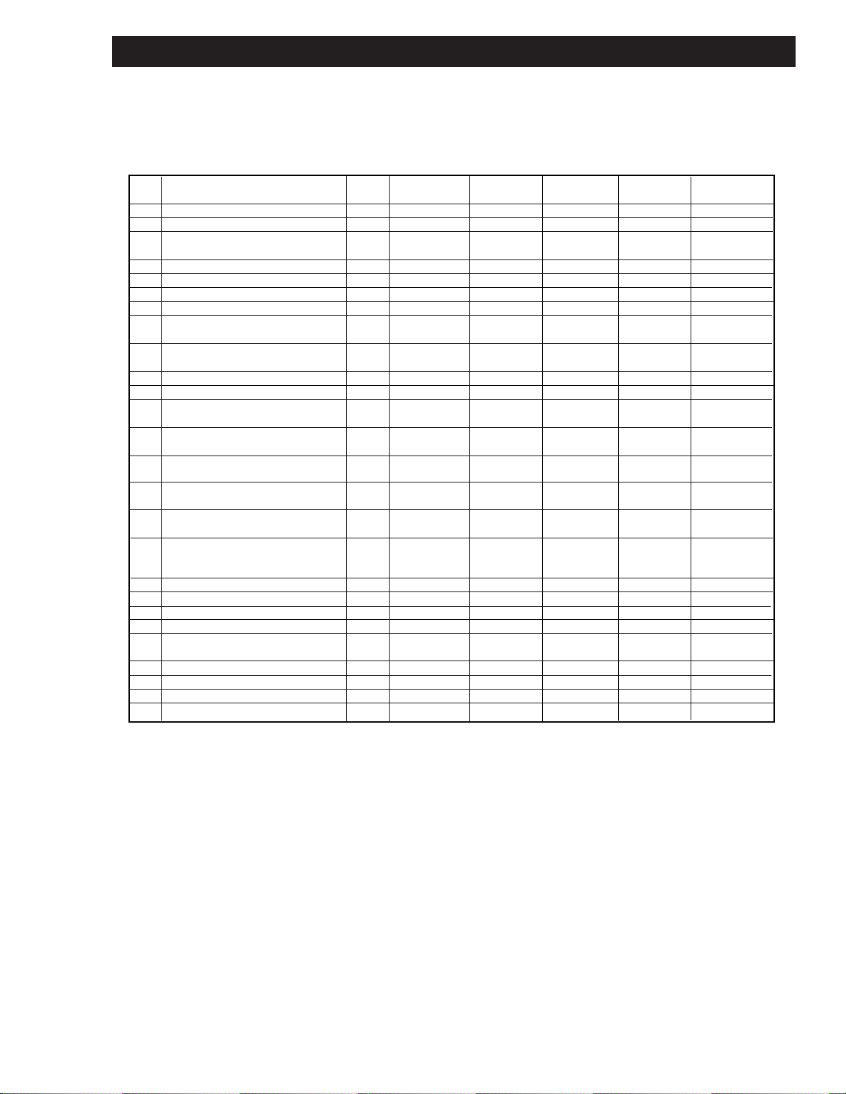
EXPLODED PRODUCT VIEW, PARTS & ORDERING INFORMATION
*** Item not shown.
∆ Denotes parts included in the Service Kit.
Parts listed are for stock models. For specific OEM models, please consult the factory.
When corresponding or ordering parts, please give complete model and serial numbers.
REF DESCRIPTION QTY 71R645-P112 71R655-P112 72R645-P112 72R655-P112 71R545-P315B
71R645-V114 71R655-V114 72R645-V114 72R655-V114
1 CAP SCREWS 8 BB570 BB570 BB570 BB570 (4) BB570
1A CAP SCREWS 4 (4) BB614B
2 HEAD 2 AT265G AT265G AT265G AT265G (1) AT265G
(1) AT265H
4 ∆ HEAD O-RING 2 AT258 AT258 AT258 AT258 AT258
5 HEX NUT 2 BC164 BC164 BC164 BC164 BC164
6 ∆ VALVE RETAINER 2 AF819A AF819A AF819A AF819A (3) AF819A
6A VALVE LIMITER 1 (1) AH406
7 ∆ LEAF VALVE 2 AF817 AF817 AF817 AF817 (2) AF817
(2) AJ827A
8 VALVE PLATE 1 AT631 AT631 AT632 AT632 (1) AT631C
(1) AT632X
9 ∆ TUBE O-RING 4 AK846 AK846 AK846 AK846 (2) AT528
10 VALVE SCREW 2 BB330 BB330 BB330 BB330 BB330B
11 ∆ CYLINDER O-RING 1 AT256 AT256 AT276 AT276 (1) AT256
(1) AJ787
12 ∆ CYLINDER 2 AT272 AT272 AT275 AT275 (1) AT272
(1) AT291
13 ∆ RETAINER SCREW 4 BB557 BB557 AT283 AT283 (2) AT283
(2) BB557
14 RETAINER PLATE 2 AT273 AT273 AT274C AT274C (1) AT715
(1) AT443A
15 ∆ PISTON CUP 2 AT329 AT329 AT280 AT280 (1) AT329
(1) AT299A
16 ROD ASSEMBLY (pressure models) 2 A T465FZ AT547BZ AT467FZ AT584BZ (1) AT453FZ
(1) AT459QZ
ROD ASSEMBLY(vacuum models) 2 AT466FVZ AT560BVZ AT469FVZ AT493BVZ
17 SHROUD 2 AT266 AT266 AT266 AT266 AT266
18 FAN 1 AT260A AT260A AT260A AT260A AT260A
18A FAN-LEAD END 1 AT259A AT259A AT259A AT259A AT259A
19 SHROUD SCREW 8 AT261 AT261 AT261 AT261 AT261
20 VALVE PLATE ASSEMBLY 1 AT633 AT633 AT634 AT634 AT633G
1 AT633A AT633A AT634A AT634A AT634X
21 RELIEF VALVE 1 AT471
22 FILTER 1 AT441
*** RUBBER FEET 4 AB319 AB319 AB319 AB319 AB319
*** SERVICE KIT 1 K557 K557 K558 K558 K634
Page 24
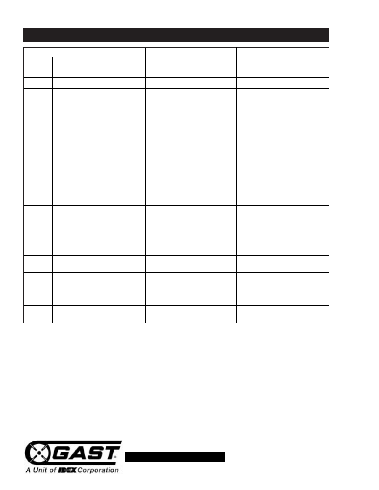
Low High Pump Won’t Excess Reason and remedy
Vacuum Pressure Vacuum Pressure Overheat Start Noise for problem.
• • • • • Filter dirty. Clean or replace.
• • • • • Muffler dirty. Clean or replace.
• • Valves dirty or valves bent.
Clean or replace.
• • Worn cup.
Repair or replace.
• • • Relief valve set too high.
Inspect and adjust.
• • Relief valve set too low.
Inspect and adjust.
• • • • • • Plugged vacuum/pressure line.
Inspect and repair.
• • Collapsed vacuum line.
Inspect and repair.
• • Low voltage, won’t start.
Check power source.
• • • Voltage wrong.
Check power source.
• • • Worn cup/piston hitting cylinder.
Replace.
• • Cylinder misadjustment.
Realign.
• • • Leaky hose or check valve.
Replace.
• • • • • Dirt or liquid on top of piston.
Inspect and clean.
• • • • • Motor not wired correctly.
Check wiring diagram/line voltage.
• • • Blown head gasket.
Replace.
TROUBLESHOOTING CHART
PART NO. 70 - 6800 G495PL (REV-G)
ISO 9001 & 14001 CERTIFIED
www.gastmfg.com
Page 25
MAINTENANCE RECORD
DATE PROCEDURE PERFORMED
For repair parts ordering information and exploded product view, visit our
website or call us at the number listed below.
We have Gast Authorized Repair Facilities throughout the world. For the most
up-to-date listing, contact one of our sales offices below:
World Headquarters
P.O. Box 97
2550
Meadowbrook Rd.
Benton Harbor, MI 490230097
Ph: 269/926-6171
FAX: 269/925-8288
www.gastmfg.com
European Sales &
Service Headquarters
Beech House Knaves Beech
Business Centre
Loudwater, High Wycombe
Bucks, England HP10 9SD
Tel: +44 1628 551500
Fax: +44 1628 551590
www.gastltd.com
Gast Hong Kong
Unit 12, 21/F, Block B
New Trade Plaza
6, On Ping Street, Shatin
N. T. Hong Kong
Ph: (852) 2690 1008
Fax: (852) 2690 1012
www.gasthk.com
www.gastltd.com
ISO 9001 & 14001 CERTIFIED
www.gastmfg.com
Page 26
Page 27
Page 28
 Loading...