

Thunder Scientific 5A-1MP Owner's Operation And Maintenance Manual

THUNDER SCIENTIFIC CORPORATION
MODEL 5A-1MP
ELECTRONIC PSYCHROMETER
RELATIVE HUMIDITY AND TEMPERATURE
MEASUREMENT SYSTEM
OPERATION AND
MAINTENANCE MANUAL
THUNDER SCIENTIFIC CORPORATION
ALBUQUERQUE, NEW MEXICO 87123-3198
623 WYOMING BLVD. S.E.

ELECTRONIC PSYCHROMETER
MODEL 5A-1MP
RELATIVE HUMIDITY AND TEMPERATURE
MEASUREMENT SYSTEM
OPERATION AND
MAINTENANCE MANUAL
ALBUQUERQUE, NEW MEXICO 87123-3198
THUNDER SCIENTIFIC CORPORATION
623 WYOMING BLVD. SE
WWW.THUNDERSCIENTIFIC.COM
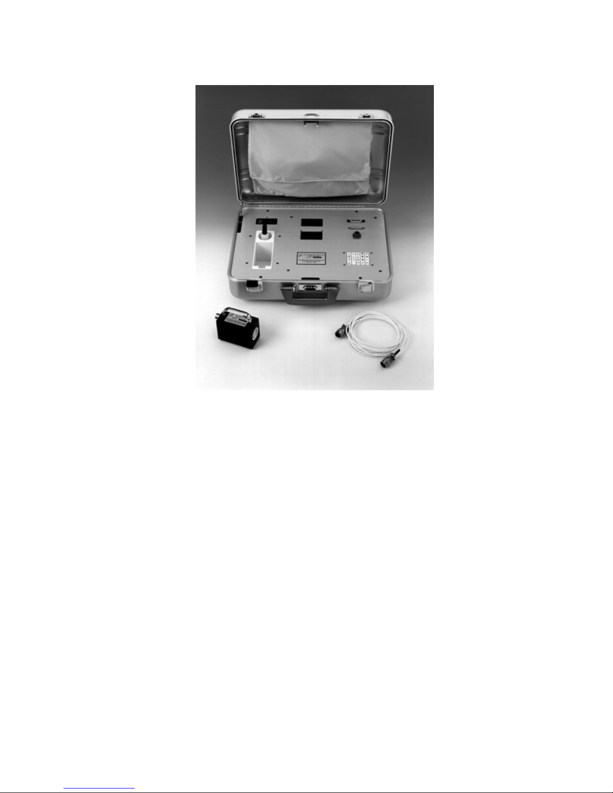
5A-1MP Laboratory Reference Psychrometer

TABLE OF CONTENTS
Section 1 - GENERAL INFORMATION
Warranty
1.1 GENERAL DESCRIPTION.........................................................................1-1
1.2 SPECIFICATIONS......................................................................................1-2
1.3 FEATURES.................................................................................................1-2
Section 2 - INSTALLATION
2.1 GENERAL..................................................................................................2-1
2.2 ELECTRICAL.............................................................................................2-1
2.3 COMPUTER/PRINTER INTERFACING......................................................2-1
2.4 IEEE 488 INTERFACING (OPTIONAL)....................................................2-3
Section 3 - OPERATION
3.1 GENERAL..................................................................................................3-1
3.2 STANDARD OPERATING PROCEDURES.................................................3-1
3.2.1 Power-up .............................................................................................3-1
3.2.2 Probe Preparation ................................................................................3-2
3.2.3 System Operation.................................................................................3-2
3.2.4 Probe # Selection.................................................................................3-3
3.2.5 Entering the Pressure ...........................................................................3-3
3.2.6 Entering the Flow Rate.........................................................................3-4
3.2.7 Enabling/Disabling the Blower .............................................................3-5
3.2.8 Enabling/Disabling the Printer..............................................................3-5
3.2.9 Displaying Desired Readings................................................................3-6
3.2.10 Changing the Time ..............................................................................3-7
3.2.11 Changing the Date ...............................................................................3-7
3.2.12 Changing the Time Interval..................................................................3-7
3.2.13 Changing the Amount of Averaging ....................................................3-8
3.2.14 Changing the Printer Options...............................................................3-8
3.2.15 Switching Between °C and °F................................................................3-9
3.2.16 Enabling the AUTO Mode.................................................................3-10

Section 4 - MAINTENANCE
4.1 PROBE WICK CHANGEOUT INSTRUCTIONS..........................................4-1
4.2 FACTORY CERTIFICATION AND RECERTIFICATION...........................4-2
4.3 NIST CERTIFICATION AND RECERTIFICATION ...................................4-3
Section 5 - RS-232 INTERFACE
5.1 GENERAL..................................................................................................5-1
5.2 RS-232 PROTOCOL ...................................................................................5-1
5.3 INITIALIZING THE HOST TERMINAL OR COMPUTER.........................5-1
5.4 CLEARING THE 5A-1MP I/O BUFFERS....................................................5-2
Section 6 - IEEE 488 INTERFACE
6.1 GENERAL..................................................................................................6-1
6.2 IEEE 488 ADDRESSING............................................................................6-1
6.3 CLEARING THE 5A-1MP BUFFERS .........................................................6-1
Section 7 - IEEE 488/RS-232 COMMAND REFERENCE
7.1 GENERAL..................................................................................................7-1
Section 8 - CABLING SPECIFICATIONS AND PINOUTS
8.1 DB25 PRINTER AND RS-232 CONNECTOR.............................................8-1
8.2 IEEE 488 CONNECTOR.............................................................................8-2

WARRANTY
Thunder Scientific Corporation warrants each instrument of its manufacture
to be free from defect in materials and workmanship.
The limit of liability under this warranty is to repair or replace any part
thereof which shall within one year after delivery to the original purchaser,
and returned by the original purchaser, prove to be defective after
examination by Thunder Scientific Corporation.
This warranty specifically excludes the probe sensors, which may become
damaged or broken due to wick changes. Shipping damage is covered by
insurance and will be honored if report is made within one week of receipt of
the instrument. Warranty returns must be authorized by the factory.

Section 1
GENERAL INFORMATION
1.1 GENERAL DESCRIPTION
The Thunder Scientific Model 5A-1MP is a microprocessor based Laboratory Standard
Psychrometer designed for precise measurement of air temperature and relative humidity.
The 5A-1MP uses a 2-bulb measurement system employing Wet and Dry calibrated
Platinum Resistance Thermometers (PRT's) operating under a controlled air velocity. One
PRT, referred to as the Dry Bulb, is used for sensing air temperature. The other PRT, the
Wet Bulb, uses a specially woven wick (or sock) to facilitate an unimpeded capillary flow of
distilled or high purity reagent water from a reservoir below. The Wet Bulb measures a
depression temperature.
The signals from the PRT's are converted to digital format, read by the microprocessor, and
mathematically corrected to temperature data. The data is then used to calculate Percent
Relative Humidity and Dewpoint Temperature.
Front panel display of any of the above data is selected by user input at the keyboard. The
upper display is the data readout device, and the lower display indicates which data or other
function is currently enabled. Upon selection of data output to this real-time LED display,
current readings are updated four to five times each second allowing for fast system
response to any changes in the sampled environment.
Printer output, enabled from the keyboard, allows for hardcopy printouts of all current
psychrometric data. Printer output is at user selected time intervals ranging from a one
minute minimum to 24 hour maximum, or at any one minute increment in between.
An Auto Mode feature is also included which, when enabled, will put the probe in
synchronous operation with the printer. In this mode, the probe aspirator will automatically
run prior to any sample for hardcopy output. After printout, the aspirator will be disabled
and will remain off until the next sample time is reached.
Bi-directional RS-232 and optional IEEE 488 communication capabilities allow for remote
operation and data retrieval when connected to a computer or terminal. All functions
available from the front panel keypad are also available over the RS-232 and IEEE 488 links
through a series of more than 40 commands.
The Model 5A-1MP is a precision laboratory grade instrument, and when operated and
handled accordingly, will provide years of excellent service.
1-1

1.2 SPECIFICATIONS
Relative Humidity (RH)
Measurement Range ....................................................................................1% to 100% RH
Resolution 0.01% RH
Guaranteed Accuracy ..............................................................................................±1% RH
Typical Accuracy ..................................................................................................±0.5% RH
Temperature
Measurement Range ...............................................................................0-100°C / 32-212°F
Resolution 0.01°C and °F
Guaranteed Accuracy .................................................................................. ±0.3°C / ±0.5°F
Typical Accuracy ......................................................................................... ±0.1°C / ±0.2°F
Data Interface
Printer Interface ........................................................................................Centronics Parallel
Computer Interface (standard)..............................................................Bi-directional RS-232
Computer Interface (optional) .................................................................................IEEE 488
Power Requirements ...............................................................................115 VAC, 50/60 Hz
(OPT) 220 VAC, 50/60 Hz
1.3 FEATURES
1) Z-80 Central Processing Unit, automatically computes percent relative humidity,
temperature, and dewpoint in °C or °F.
2) Bi-directional RS-232 and IEEE 488 computer interfaces allow for remote
operation/data collection.
3) Battery backed-up real time clock.
4) Centronics printer interface with user selectable input intervals from one minute to 24
hours in one minute increments.
5) AUTO mode capability enables probe aspirator for one minute prior to each printout.
6) Non susceptible to contamination by chemicals or long term exposure to high relative
humidity and temperature.
7) Certification of Traceability to the National Institute of Standards and Technology.
8) Direct NIST certification available.
1-2
Section 2
INSTALLATION
2.1 GENERAL
The 5A-1MP is designed as a portable test instrument requiring no special physical
installation. The instrument must, however, be connected to a source of AC power (Section
2.2) and may be connected to a printer and/or computer (Sections 2.2, 2.3, 2.4) for remote
data collection and coefficient manipulation (also see Figures 2-1, 2-2, and 2-3).
2.2 ELECTRICAL
Using the 6' power cord provided, connect the 5A-1MP to a 115 VAC, 50/60 Hz, grounded
outlet.
2.3 COMPUTER/PRINTER INTERFACING
The RS-232 computer interface shares a connector with the parallel printer interface (refer to
Section 8.2 for the specific pinouts). Since the computer and printer interfaces are sharing
the same connector, only the cables supplies by the factory should be used. When replacing
or repairing factory supplies cables, the wiring connections described in Section 8.1 must be
followed.
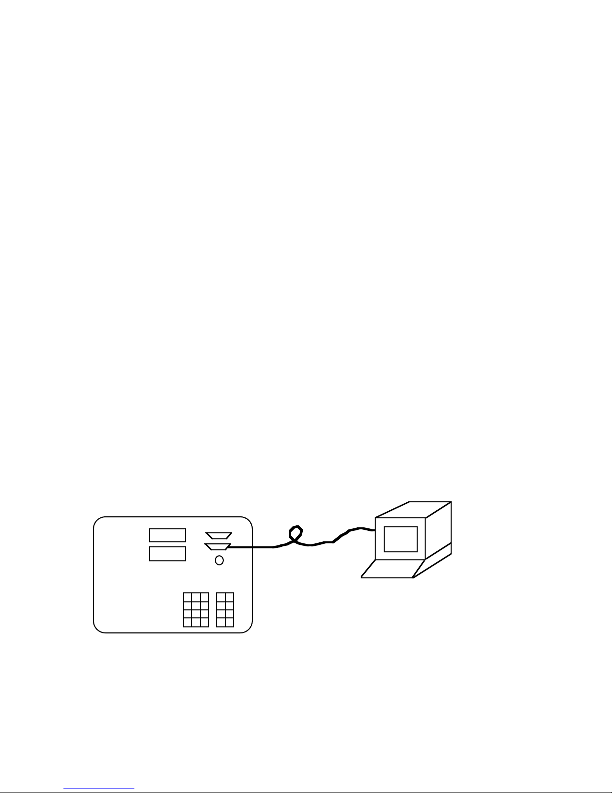
If a computer is to be connected via the RS-232 interface (but no printer is to be connected),
use the small round interface cable with the hooded DB25 connectors at each end. Plug the
cable end marked "5A-1MP" into the DB25 connector on the psychrometer. Plug the other
end into an RS-232 port of a computer or terminal. Depending upon the connections at the
computer terminal, a gender changer, null modem adapter, or other interface
cables/connectors may be required.
Communicating with the 5A-1MP via the RS-232 interface is discussed in Section 5.
RS-232 Terminal
or Computer
Small, Round
Serial Cable
Figure 2-1
Computer/Terminal Connection
2-1
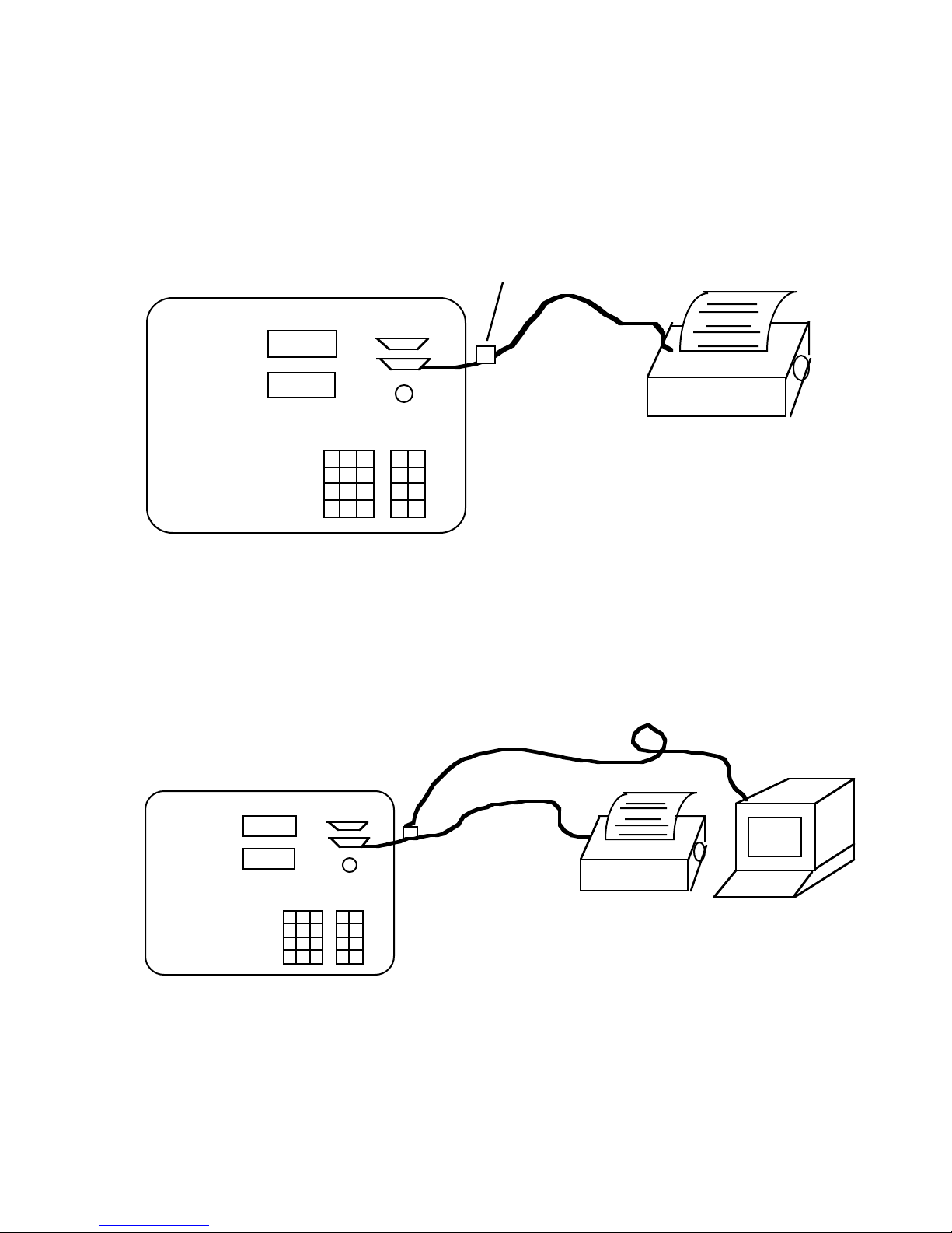
If a printer is to be connected, use the flat ribbon type cable which contains a Centronics type
36 pin ribbon-D connector on one end, and two DB25 connectors on the other end. Plug the
36 pin Centronics connector into the mating connector of the printer. Plug one of the DB25
connectors into the mating connector of the psychrometer. Note that only one of the DB25
connectors is of the proper gender to mate with the psychrometer.
Unused Connector
Flat Ribbon
Cable
Figure 2-2
Printer Connection
If both the printer and computer are to be connected to the psychrometer, connect the printer
first by following the procedures previously outlined (see Figure 2-2). Then plug the RS-232
cable into the unused connector on the printer cable. This connection scheme allows both the
printer and computer to communicate with the 5A-1MP simultaneously.
Small, Round Serial Cable
Flat Ribbon Cable
RS-232 Terminal
or Computer
Figure 2-3
Computer/Terminal and Printer Connections
2-2

2.4 IEEE 488 INTERFACING (OPTIONAL)
The 5A-1MP may be connected to an IEEE 488 bus via its 24 pin D-type IEEE 488
connector located on the top panel above the computer/printer interface connector (see
Figure 2-4). IEEE 488 communication with the 5A-1MP is discussed in Section 8. See
Section 8.1 for wiring specifications.
IEEE 488 Cable
Flat Ribbon Cable
Figure 2-4
IEEE 488 Connection
IEEE 488 Computer
2-3

Section 3
OPERATION
3.1 GENERAL
The 5A-1MP is capable of operation in either manual or automatic mode, invoked either
from the keypad, the serial interface, or the IEEE 488 interface. In general, operation
consists of filling the probe reservoir with pure distilled water, turning the 5A-1MP ON,
entering the current barometric pressure, and enabling the blower (or aspirator) motor.
After taking data, the blower motor should then be turned off until another sample is
required.
3.2 STANDARD OPERATING PROCEDURES
3.2.1 Power-up
Ensure that installation is performed in accordance with Section 2. Press the power switch
ON. The LED Displays should indicate the time of day on the upper panel, and P--7
(meaning parameter 7, the time) on the lower panel. If for some reason the power-up mode
appears incorrect, either cycle the power off and on again or execute a cold reset. A cold
reset is executed by pressing the reset key while holding down the decimal point key. This
procedure performs exactly the same function as cycling the power off and on. All values,
functions, and modes of the system are restored to their power-up default status.
NOTE 1: Due to the use of CMOS circuitry within the 5A-1MP, peripherals such
as a printer may be supplying enough power to the 5A-1MP to prevent it from fully
cycling down during a power-off sequence. This failure to fully cycle down may
cause an invalid power-up sequence. To prevent this problem, one or both of the
following should be performed when peripheral devices are connected to the 5A1MP:
A) Power down peripherals when powering down the 5A-1MP.
When powering up, power up the 5A-1MP first, then power up the
peripherals.
B) Hold down the decimal point key on the keypad while either
powering up or pressing RESET. This forces the 5A-1MP through
the proper power up initialization sequence regardless of any previous
failure to fully cycle down.
3-1

3.2.2 Probe Preparation
The black probe housing contains two Platinum Resistance Thermometers (PRT's) which
are used for measuring the air temperature (called the Dry Bulb temperature) and the
depression temperature (called the Wet Bulb temperature). The Wet Bulb sensor is the one
which is covered by the woven cotton wick. During operation, the wick remains wet by
drawing water (through capillary action) from the reservoir in the bottom of the probe
housing. The reservoir must be filled prior to operation, and drained after operation
allowing the wick to dry. (The probe should never be stored with a wet wick, as a stagnant
wet wick provides an excellent media for the growth of micro-organisms (bacteria), thus
altering the accuracy of the instrument).
Fill the reservoir with pure distilled water by removing the filler plug (the larger of the two
screws) on the bottom plate of the probe housing. A dime usually works well for this
purpose. Using the bottle and dropper provided, fill the reservoir to the bottom of the filling
hole, while holding the probe so that the round white teflon shaft is vertical, and the motor
end is downward. Replace the filler plug and tighten. Squirt several droppers full of water
directly on the wick covering the Wet Bulb sensor. This flooding procedure is used to
clean the wick and flush away possible contaminants. Dry the probe by gently shaking out
excess water from within the teflon shaft portion of the probe. Avoid tapping or banging
the probe. Cotton swab sticks (Q-tips) may be needed to thoroughly dry the inside of the
white teflon probe shaft. Also dry the outside with a clean cloth while watching for leaks
around the bottom of the probe at the edges of the reservoir cover. The reservoir cover is
sealed by a rubber gasket and secured by the small screw in the center. Tighten this center
screw as necessary.
Place the probe in the environment to be tested and connect the white power signal cable. If
multiple probes were calibrated with this 5A-1MP, ensure that the probe number and cable
number match, as they were calibrated from the factory as a set. Connect the other end of
the cable to the mating connector on the 5A-1MP.
3.2.3 System Operation
In order to measure relative humidity and other psychrometric data in the test environment,
the user must
1) Prepare the probe. (Refer to Section 3.2.2).
2) Enter the probe number. (Refer to Section 3.2.4).
3) Enter the current pressure. (Refer to Section 3.2.5).
4) Aspirate the probe. (Refer to Section 3.2.7).
5) Wait approximately 1 minute for stabilization.
6) Display and/or print data. (Refer to Sections 3.2.8, ).
7) Stop probe aspiration. (Refer to Section 3.2.7).
If the psychrometer is being operated within a humidity generator (such as the Thunder
Scientific Model 8500 Automated Two-Pressure Humidity Generator), fittings are available
in order to aspirate the probe from the humidity generator rather than the blower motor.
When using external sources such as this for aspiration, the flow rate of the source must be
known and entered into the 5A-1MP. (Refer to Section 3.2.6, Entering the Flow Rate).
3-2

3.2.4 Probe # Selection
If the 5A-1MP has been supplied with more than one probe, the probe number which is
currently connected to the system must be entered so that the appropriate calibration
coefficients will be used in all mathematical calculations of Dry Bulb and Wet Bulb
temperature. Failing to enter the probe number of the currently connected probe will result
in erroneous data. Greatest accuracy will also be achieved when using a numbered probe
cable which matches the number on the probe, since the probe and cable are factory
calibrated as a set.
Enter the probe number by pressing
0
PROBE
SET
n
ENTER
where n is a number between 1 and 4 corresponding to the number on the connected cable
and probe. The power-up default is always Probe 1. The probe number may also be
changed from either the IEEE 488 or the RS-232 interface. (Refer to PROBe command,
Section 7).
3.2.5 Entering the Pressure
For proper RH calculations, the absolute pressure of the test environment must be known
and entered (in inches of mercury) into the 5A-1MP. The actual pressure may be measured
using an absolute pressure transducer available from a number of different manufacturers.
An alternate method is to obtain the approximate barometric pressure from the nearest
airport or weather station. Be sure to obtain the actual pressure before any altitude
adjustments have been applied. Since the pressure must be entered into the 5A-1MP in
inches of mercury, some common conversions follow.
in Hg = PSIA * 2.03602
= Pa * 0.00014503774
= kPa * 0.14503774
= atm * 29.921
= mm Hg/25.4
= in H2O/13.6086
= mm H2O * 1.8665
= Torr/25.4
= Bar * 29.53
= mb/33.8638
3-3

Convert the pressure to inches of mercury if required and enter it in the following manner;
however, use the appropriate pressure. For example, to enter a pressure of 30.12 inches of
mercury, press
PRESS.
LED's display RH on top, P--1 on bottom.
SET
Enables SET mode. Displays Pressure setting (factory default 29.92)
(Note Press. and Set are same color).
3
30.12 Displays 9.923
0
30.12. Displays 9230
.
30.12. Displays 9230.
1
30.12. Displays 230.1
2
30.12. Displays 30.12
ENTER
Ends SET mode. Display reverts to previous reading.
This new pressure value only remains valid until changed again from the keypad, serial
interface or IEEE 488 interface, or until the unit is cold reset as in Section 3.2.1. Note that
the decimal point is required but that it will automatically trail the second digit entered
unless the decimal point key is pressed during the entry sequence. To change the pressure
from either the RS-232 or IEEE 488 interface, refer to the PRESsure command, Section 7.
To save the currently entered pressure as the power up default pressure, use the SAVE
command, Section 7.
3.2.6 Entering the Flow Rate
When aspirating the probe from an external source such as an 8500 Automated TwoPressure Relative Humidity Generator, the system mass flow rate may be entered into the
psychrometer. As an example, a mass flow rate of 100 SLPM would be entered by
pressing
3-4

FLOW
SET
1
0
0
.
0
ENTER
This number only remains valid until changed again from either the keypad, the IEEE 488,
or the serial interface, or a cold reset is performed. (Refer to Section 3.2.1, Power-Up).
Also, anytime the unit is aspirated by enabling the internal blower motor, the flow rate
entered is ignored and all calculations are performed utilizing a preset flow rate determined
during factory calibration. If probe aspiration is always accomplished with the internal
blower, the flow rate need not be altered from its power-up default value. The flow rate may
also be set from either the RS-232 or IEEE 488 interface. (Refer to FLOW command,
Section 7).
3.2.7 Enabling/Disabling the Blower
BLWR
ON
Pressing the
OFF
key enables and disables the blower motor within the probe. When
enabled, the leftmost dot of the lower LED display will illuminate. The blower should be
enabled for at least 30 seconds to 1 minute prior to taking readings in order to allow the
system to stabilize. After the desired readings have been taken, disable the blower by
pressing the same key again. The blower may also be controlled from either the RS-232 or
IEEE 488 interface. (Refer to BLOWer command, Section 7). Note that there is a normal
1 to 2 second delay associated with blower turnoff.
3.2.8 Enabling/Disabling the Printer
If a printer is connected to the psychrometer. (Refer to Section 2.3, Computer/Printer
Interfacing), current printouts of all relevant psychrometric data is available.
To enable the printer,
PRINT
ON
press the
OFF
key on the keypad. The second dot from the left on the lower display
will illuminate, and data will then be printed at the specified time intervals. (Refer to Section
3.2.12, Changing the Time Interval). Pressing the key again disables the printer.
PRINT
NOW
The
key may be used at any time to immediately send one line of data to the
printer.
The start of each page is preceded with a header and the end of each page is appended with
a formfeed (or top of form), provided that headers and formfeeds are enabled. (Refer to
Section 3.2.13, Printer Options). The printer may also be controlled from either the RS-232
or IEEE 488 interface. (Refer to PRINter command, Section 7).
3-5

3.2.9 Displaying Desired Readings
Ω
With the 5A-1MP in the normal parameter display mode, indicated by a "P" on the leftmost
digit of the lower LED display, select the desired display parameter by pressing any of the
numeric keys. The keys and associated parameters are listed below:
Key Display Parameter
0
PROBE
Probe #
1
RH
RH
2
DP
Dewpoint
3
DRY TMP
Dry Bulb Temperature
4
WET TMP
5
DRY
6
Ω
WET
7
TIME
8
DATE
9
INTRVL
Wet Bulb Temperature
Dry Bulb Resistance
Wet Bulb Resistance
Time of Day
Date
Time Interval between printouts
Notice that the display parameters relate to the black text on the bottom of the keys.
3-6

SET
The blue text at the top of some of the keys indicates that when using the
key, it is
the parameter in blue which will be changed. (Refer to Sections 3.2.4-3.2.6, 3.2.10-3.2.14
for use of the SET key). Those keys without blue text have identical SET and DISPLAY
parameters. (Exceptions are the Dry Ω and Wet Ω which have no corresponding SET
parameters).
3.2.10 Changing the Time
7
TIME
h
key on the keypad. To change the time, press
m
m
ENTER
Display the time by pressing the
TIME
SET
h
where hh and mm are the hours and minutes desired. Time is entered in 24 hour military
format. For example, the time 6:15 p.m. must be entered as 1815. The time may also be set
from either the RS-232 or IEEE 488 interface. (Refer to TIME command, Section 7).
3.2.11 Changing the Date
8
Display the date by pressing the
DATE
key on the keypad.
Change the date by pressing
DATE
SET
m
m
d
d
ENTER
where mm and dd are the month and day respectively. For example, December 25 is
entered as 1225. The date may also be set from either the RS-232 or IEEE 488 interface.
(Refer to DATE command, Section 7).
3.2.12 Changing the Time Interval
9
Display the printout time interval by pressing the
INTRVL
key on the keypad. The
numbers shown on the upper display represent the hours and minutes between printed
3-7

readings whenever the printer is enabled (note that the printer is automatically enabled in
AUTO mode).
To change the interval from its 1 minute default, press
INTRV L
where hh and mm represent the desired hours and minutes between printouts. Allowable
intervals range from a minimum of 0001 (1 minute) to a maximum of 2359 (23 hours, 59
minutes). The interval may also be set from either the RS-232 or IEEE 488 interface.
(Refer to INTErval command, Section 7).
3.2.13 Changing the Amount of Averaging
On power-up, the averaging amount is set to 0 and no internal averaging takes place. While
averaging is not normally required for stable readings, its use may prove beneficial in
unstable and/or electrically noisy environments. The 5A-1MP uses a weighted sum
averaging technique where by the currently displayed value is multiplied by n, added to the
new value, then the total is divided by n + 1. To change the averaging from its 0 default
value, press
AVERAGE
where nnnn is a number between 0000 and 9999 inclusive, with reasonable values between 0
and 100.0 inclusive. Note that fractional numbers are also valid. The averaging amount
remains valid until changed, or until a cold reset is performed. (Refer to Section 3.2.1,
Power-Up). Averaging may also be changed from either the RS-232 or IEEE 488 interface.
(Refer to AVERage command, Section 7).
SET
SET
h
n
h
n
m
n
m
n
ENTER
ENTER
3.2.14 Changing the Printer Options
Printer options available from the keypad include
A) Enabling/disabling formfeeds.
B) Enabling/disabling the header.
C) Setting the end of line terminator to
1) Carriage return only.
2) Line feed only.
3) Carriage return, line feed.
4) Line feed, carriage return.
D) Setting the number of lines per page.
3-8

The factory default printer options are set at and broken down as follows:
0360
ABCC
A =0for a carriage return only at the end of each line (factory default).
1 for a line feed only.
2 for a carriage return then line feed.
3 for a line feed then carriage return.
B =0for no header and no formfeeds.
1 for header, but no formfeeds.
2 for formfeeds, but no header.
3 for header and formfeeds (factory default).
CC = 00-99 lines per page. (factory default=60).
To change the printer options, first determine the appropriate 4 digit number ABCC from the
previous descriptions, then enter the number by pressing
RT O PT
If the printer was enabled, or if the
SET
A
B
PRINT
NOW
C
C
ENTER
key had been used prior to setting the printer
options, the printer may need to be disabled then re-enabled to make the new printer options
become valid (primarily when changing the lines per page). The options entered remain
valid until changed again or a cold reset is performed. (Refer to Section 3.2.1, Power-Up).
Printer options may also be set from either the RS-232 or IEEE 488 interface. (Refer to
FORMfeed, HEADer, ENDLine, and LINEs commands, Section 7). Current printer
options may also be stored as power-up defaults through the use of the SAVE command,
Section 7.
3.2.15 Switching Between °C and °F
C / F
The 5A-1MP powers up in °F mode. To switch to °C, press the
key. The
rightmost dot on the lower LED display will illuminate. Return to °F with the same key.
This key affects the display and printer temperature scales only, and does not affect the
temperature scale of the serial and IEEE 488 interfaces which are always °C. The
temperature scale is also selectable through either the RS-232 or IEEE 488 interface. (Refer
to DEGRees command, Section 7).
3-9

3.2.16 Enabling the AUTO mode
AUTO
ON
Enable the AUTO mode by pressing the
OFF
key. The third dot from the left on the
lower display will illuminate indicating the AUTO mode is now enabled. The AUTO mode
also enables the printer (illuminates the second dot) and controls the operation of the blower
motor (the first dot). In AUTO mode operation, the 5A-1MP will automatically enable the
blower exactly 60 seconds prior to each printout of data which occurs at the specified time
interval. (Refer to Section 3.2.12, Changing the Time Interval). The blower will then be
disabled immediately following each print, and will remain off until 60 seconds prior to the
next print time. In this way, the blower remains on for only 1 minute during each sampling
time interval, greatly extending the service of the blower motor which has a 300 hour
nominal run life. Note that if the interval is set to 1 minute, the blower will remain on
continuously.
NOTES:
1) While in AUTO mode, the printer remains enabled and cannot be disabled by the
user.
PRINT
ON
The
OFF
key is therefore locked out and has no effect.
2) Once within the 60 seconds prior to each print time when the blower is enabled, it
may not be disabled by the user.
BLWR
ON
The
OFF
key is therefore locked out and has no effect during this 60 second
time interval.
AUTO
ON
The AUTO mode is disabled by pressing the
OFF
key again. Disabling AUTO mode
also disables the printer and blower motor, restoring them back to user control from the
keypad. The AUTO mode may also be controlled from either the RS-232 or IEEE 488
interface. (Refer to AUTO command, Section 7).
3-10

Section 4
MAINTENANCE
4.1 PROBE WICK CHANGEOUT INSTRUCTIONS
The CK-1 Wick Changeout Kit is provided to easily change wicks in the sensing probe.
Wick changes should be performed after approximately 40 hours of operation, or more
often, particularly if the instrument is in a dirty environment. A replacement wick supply
should be kept on hand and can be ordered from the factory in advance of the need.
Consult the factory for current price information in the event a replacement supply is
needed.
To change the wick, perform the following:
1) Place probe upside down upon two blocks of wood or other material, one on each
side of the probe handle.
2) Remove reservoir plug, cover screw, and rubber feet.
3) Gently pry reservoir cover with plastic tool and remove.
4) Carefully remove the four housing retainer screws located in the corners of the probe;
they join the two halves of the probe.
5) Gently remove bottom half of probe housing, feeding the wick through the vertical
teflon wick tube. Keep the large horizontal teflon air sleeve in place during removal.
Note - Blower motor is also loose once housing is removed.
6) Lift teflon air sleeve up and off the sensor mounts taking care to feed the wick
through the air sleeve avoiding any lateral movement and undue strain upon the sensor.
7) The sensor and wick are now in the open where the wick may be removed. Using the
dropper provided, apply several drops of ethyl alcohol to the portion of the wick
covering the sensor. Allow to soak for approximately one minute, replenishing the
alcohol as evaporation occurs.
8) Using one of the picks provided, gently probe the wick covering the sensor to loosen.
9) Using the curved tweezers provided, very gently push the wick up on itself or up on
the sensor, assisting with the other hand from the reservoir side. (The wick construction
is very similar to a "Chinese finger puzzle" in that pushing tends to release it where
pulling only tightens the wick and compounds the problem of removal.) The wick
should expand. When this occurs, use the tweezers to slide the wick from the sensor.
4-1

CAUT ION!
IF WICK IS FROZEN TO THE SENSOR WITH DEPOSITS DUE TO
CONTAMINATED WATER, DO NOT
FORCE. THIS WILL BREAK THE SENSOR
LEADS, CAUSING EXPENSIVE REPAIR COSTS. IF ALCOHOL DOES NOT
LOOSEN THE DEPOSIT, RETURN TO THUNDER SCIENTIFIC FOR REMOVAL.
THUNDER SCIENTIFIC IS NOT RESPONSIBLE FOR LEAD BREAKAGE AND/OR
SENSOR REPLACEMENT IF SUCH OCCURS.
If a wick changeout schedule is maintained and the water is drained from the probe after
each use this problem should not occur.
10) Apply provided finger cots to the thumb and index finger of each hand. Soak a
clean cloth with alcohol and remove all traces of talcum from the outer surfaces. If this
is not done, the wick becomes contaminated.
11) The replacement wicks are supplied in a sealed vial of alcohol. Remove wick from
the vial.
12) Using the taper tool provided, push the wick onto the tool approximately one inch or
more, causing expansion by pushing on the wick.
13) Remove from tool and clip frayed end square.
14) Slide wick gently onto sensor and over the teflon to the shoulder.
15) Using the dropper, apply several drops of water on the wick at the sensor. Note
wick expands slightly, indicating water retention. Gently form the wick around end of
sensor and flatten between the sensor and wick tube to offer minimum wind resistance.
16) Feed wick through teflon air sleeve, slide sleeve over teflon sensor mounts, and seat
it on the probe half.
17) Feed wick through wick tube in bottom probe half and mate the probe halves. Coil
wick inside reservoir and replace cover.
18) Replace four corner screws, rubber feet, and reservoir plug.
4.2 FACTORY CERTIFICATION AND RECERTIFICATION
Factory certification is initially provided at no charge with each new instrument. Since
certification is typically good for one year, the instrument should be recertified by the
factory on an annual basis. Generally, three temperature calibration points and three
humidity check points are sufficient. If the instrument requires more than general cleaning,
a reconditioning charge will also be applied. Consult the factory for current pricing
information.
4-2

4.3NIST CERTIFICATION AND RECERTIFICATION
If it is desired that the instrument be certified by the National Institute of Standards and
Technology (NIST), all NIST charges are passed net plus 20% to the customer, plus F.O.B.
charges to and from, plus insurance coverage.
In the case of NIST certification, it is recommended (although not required) that the
instrument be sent to Thunder Scientific, so that NIST certification can be performed in
conjunction with recommended annual factory calibration service.
4-3

Section 5
RS-232 INTERFACE
5.1 GENERAL
Virtually all functions available through the keypad are also available through the RS-232
interface. Each command available over the RS-232 interface is included in Section 7 and is
provided with a description, normal syntax and usage, and both computer and terminal
communication examples. There are basically two types of commands available; one for
input, one for output. Input commands consist of the basic command word, followed by a
question mark (?), and are used to input information from the 5A-1MP to the computer or
terminal.
Output commands consist of the basic command word, followed by an equals sign (=), and
the numeric or string data, and are used to output information from the terminal or computer
to the 5A-1MP. Spaces are completely ignored by the 5A-1MP and are neither
acknowledged nor echoed. Errors in command syntax do not generate error messages. The
command in error is simply ignored.
For wiring/cabling instructions, refer to Section 2.3.
5.2 RS-232 PROTOCOL
All commands and data sent to and from the 5A-1MP are done so at the following factory
preset parameters:
Baud Rate: 1200 (Factory selectable from 300-9600)
Word Size: 8 Bits
Stop Bits: 1
Parity: None
The 5A-1MP only requires one stop bit when receiving, but will use two stop bits while
sending. The computer terminal may be set to either one or two stop bits, depending on
user preference.
5.3 INITIALIZING THE HOST TERMINAL OR COMPUTER
Ensure that a computer/terminal is connected in accordance with Section 2.3. In order to
communicate over the RS-232 interface, the terminal or computer must be configured to
operate with the same protocol as that of the 5A-1MP. For the proper protocol parameters,
refer to Section 5.2, RS-232 Protocol.
The following example illustrates the initialization for IBM BASICA when the 5A-1MP
interface is connected to com1 of the computer.
5-1

10 'INIT ROUTINE FOR 5A-1MP TO COM1 CONNECTION.
20 'SET COM1 TO #1.
30 OPEN "COM1:1200,n,8,2,cs,ds,cd,rs" as #1
40 '
50 '
60 'NOW CLEAR 5A-1MP DATA BUFFERS
70 '
80 PRINT #1, CHR$ (3);
90 '
100 '
110 'DISABLE 5A-1MP ECHOING.
120 PRINT #1, "ECHO=OFF"
130 '
140 '
150 'WAIT A BIT.
160 FOR X=1 TO 50:NEXT X
170 '
180 'CHECK AND CLEAR COM1 INPUT BUFFER.
190 IF EOF(1) THEN 210
200 A$=INPUT$ (LOC(1), #1)
210 '
220 '
230 '
240 'INITIALIZATION COMPLETE. START COMMAND PROGRAMMING.
.
.
.
5.4 CLEARING THE 5A-1MP INPUT BUFFERS
After computer or terminal initialization and prior to actual communications between the
terminal or computer and the 5A-1MP, the data I/O buffers of the 5A-1MP should be
cleared. To clear the I/O buffers from a terminal, send a Control C or ASCII Code 3
(ETX).
To clear the I/O buffers from a computer, send a CHR$ (3). For an example of this, see
lines 60-80 of the initialization program of Section 5.3.
5-2

Section 6
IEEE 488 INTERFACE
6.1 GENERAL
Virtually all functions available through the keypad are also available through the
optional IEEE 488 interface. Each command used over this interface is included in
Section 7 and is provided with a description, normal syntax and usage, and an HP BASIC
example. There are basically two types of commands available; one for input, one for
output. Input commands consist of the basic command word, followed by a question
mark (?), and are used to input information from the 5A-1MP to the computer.
Output commands consist of the basic command word, followed by an equals sign (=),
and the numeric or string data, and are used to output information from the computer to
the 5A-1MP. Spaces are completely ignored by the 5A-1MP. Errors in command syntax
do not generate error messages. The command in error is simply ignored.
6.2 IEEE 488 ADDRESSING
All 5A-1MP'S are initially set to an IEEE 488 address of 5 when originally shipped and
during factory calibration/recalibration. The address is not hardware selectable, but is
software selectable, and may be changed to any value between 0 and 9. Once changed,
the new address becomes permanent (until changed again). Since this address is stored in
non-volatile zero-power RAM, there is no limit to the number of times which the address
may be altered. To change the address, refer to the ADDR command in Section 7. Note
that the SAVE command does not affect the stored address.
6.3 CLEARING THE 5A-1MP I/O BUFFERS
After power-up, it is good practice to clear the 5A-1MP I/O buffers prior to beginning
IEEE 488 communications.
Executing the HP BASIC command CLEAR 7 clears all devices on the bus, while
CLEAR 705 clears the 5A-1MP only. Either is sufficient to clear the 5A-1MP I/O
buffers.
The HP BASIC CLEAR command may also be used at any time to clear pending 5A-
1MP outputs and garbage in the 5A-1MP input buffer due to aborted OUTPUT 705
commands.
Refer to the following example:
10 ASSIGN @ PSY TO 705 !Set up communication path
20 CLEAR @ PSY !Clear 5A-1MP I/O buffers
.
.
.
6-1

Section 7
COMMAND REFERENCE
7.1 GENERAL
The following is a comprehensive list of commands available over the RS-232 and IEEE
488 interfaces. Each of the commands is organized in alphabetical order on the remaining
pages. Each command contains examples of its usage and proper syntax when connected to
a computer on the IEEE 488 bus, or to a computer/terminal on the RS-232 interface. Note
that only the first four characters of each command are actually required when
communicating with the 5A-1MP, and additional characters are simply ignored.
Note also that each command ends with either a questions mark (?), (when requesting data
from the 5A-1MP), or an equal sign (=) followed by data (when sending data to the 5A1MP).
In general, commands which alter the psychrometer's configuration or calibration only
remain in effect until power is removed or a cold reset is performed. However, all
calibration coefficients, the printer configuration, the default pressure, and the IEEE 488
device address may be stored in non-volatile memory as the new power-up default values.
Refer to the ADDRess, SAVE and RESTore commands for further details.
COMMANDS GROUPED BY CATEGORY
Temp, RH, Dew Point DRYTemp
WETTemp
RH
DP
Saturation Vapor Pressures DRYSvp
WETSvp
DPSVp
SET Parameters AVERage
FLOW
PRESsure
PROBe
Real Time Clock TIME
DATE
Printer Control PRINt
FORMfeed
HEADer
LINEs
ENDLine
INTErval
7-1

Misc Control AUTO
BLOWer
DEGRees
DISPlay
RESEt
RESTore
SAVE
Calibration Parameters DRYOhms
WETOhms
DZERo
DSPAn
DLINearity
WZERo
WSPAn
WLINearity
DOZEro
DOSPan
DOLInearity
WOZEro
WOSPan
WOLInearity
RS-232 Parameters ECHO
IEEE 488 Parameters ADDRess
7-2
 Loading...