

Page 1
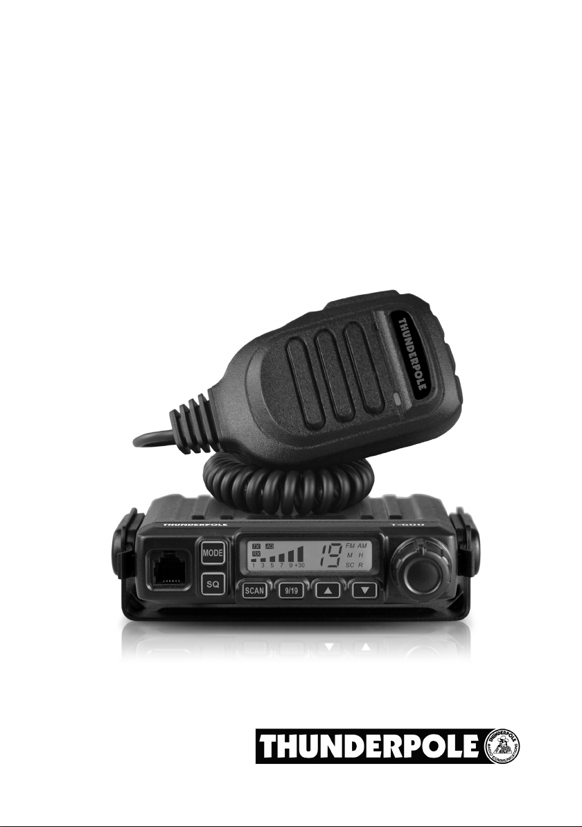
T-600
MULTI STANDARD PROGRAMMABLE
27 MHz CB MOBILE TRANSCEIVER
OWNER’S MANUAL
Page 2

Declaration of Conformity
EC Certicate of Conformity
(to EC Directive 2014/53)
DECLARATION OF CONFORMITY
With the present declaration, we certify that the following products :
THUNDERPOLE T-600
comply with all the technical regulations applicable to the above mentioned products
in accordance with the EC Directive 2014/53/EU.
Type of product : CB Transceiver
Details of applied standards :
EN 60950-1: 2006 + A11: 2009 + A1: 2010
+ A12: 2011 + A2: 2013
EN 62311: 2008
EN 301 489-1 V2.2.0 (2017-03)
EN 300 433 V2.1.1 (2016-05)
Manufacturer :
THUNDERPOLE
1 Hartburn Close, Crow Lane Ind Est
Northampton, NN3 9UE, England
Tel. +44 1604 402403
E-mail : [email protected]
Contact Reference :
Alan Crumpton
Tel. +44 1604 402403
E-mail : [email protected]
Northampton, 30/04/2021
Mr. Alan Crumpton
(General Manager)
NOTICE!
It is recommended to carefully read this owner’s manual before using the product. This will also help the user to
prevent using the radio in violation of the regulations valid in the country where the product is used, as well as to
avoid any possible interference with other services.
Page 3
Index - Introduction - Contents of the box
Index - Introduction - Contents of the box . . . . . . . . . . . . . . . . . . . . . . . . . . . . . . . . . . . . . . . . . . . . . . 1
Controls and operation . . . . . . . . . . . . . . . . . . . . . . . . . . . . . . . . . . . . . . . . . . . . . . . . . . . . . . . . . . . 2 - 4
Installation . . . . . . . . . . . . . . . . . . . . . . . . . . . . . . . . . . . . . . . . . . . . . . . . . . . . . . . . . . . . . . . . . . . . . . . . 5
Frequency band selection / table . . . . . . . . . . . . . . . . . . . . . . . . . . . . . . . . . . . . . . . . . . . . . . 6
User Information . . . . . . . . . . . . . . . . . . . . . . . . . . . . . . . . . . . . . . . . . . . . . . . . . . . . . . 7
Specications . . . . . . . . . . . . . . . . . . . . . . . . . . . . . . . . . . . . . . . . . . . . . . . . . . . . . . . . . . . . . . . . . . . . . 8
NOTICE !
Before using this transceiver, please check it has been programmed on the correct frequency band
and operating mode allowed by the regulations valid in the country where the product is used. If not,
please change the frequency band(see page 6).
NOTE: This transceiver is factory pre-programmed on the UK frequency band (UK 40CH FM 4W).
Congratulations!
Congratulations for selecting and purchasing a quality THUNDERPOLE product.
This transceiver includes a number of advanced functions and systems, therefore it is important to carefully
read this owner’s manual before using the radio. With the correct use of this product in accordance with the
operating method described in this manual, the product will offer trouble free use for many years.
THUNDERPOLE is constantly engaged in developing and providing quality products meeting the customers
requirements, however any suggestions or comments on this product that might help us to improve quality are
warmly welcome.
The THUNDERPOLE T-600 is a CB transceiver using advanced hardware and software design, it includes a
special multi-standard programmable circuit, which allows you to program the frequency band and operating
mode in compliance with the regulations valid in the various European countries. Therefore this product can be
used in any country of the European Community.
The radio is delivered factory pre-programmed on the UK frequency band (UK 40CH FM 4W).
Contents of the box
Please check that all the following items are contained in the box :
• Main unit (transceiver)
• DC power cord with fuse holder and fuse
• Condenser microphone
• Car mounting bracket
• Microphone bracket
• Owner’s manual
- 1 -
Page 4
Controls and operation
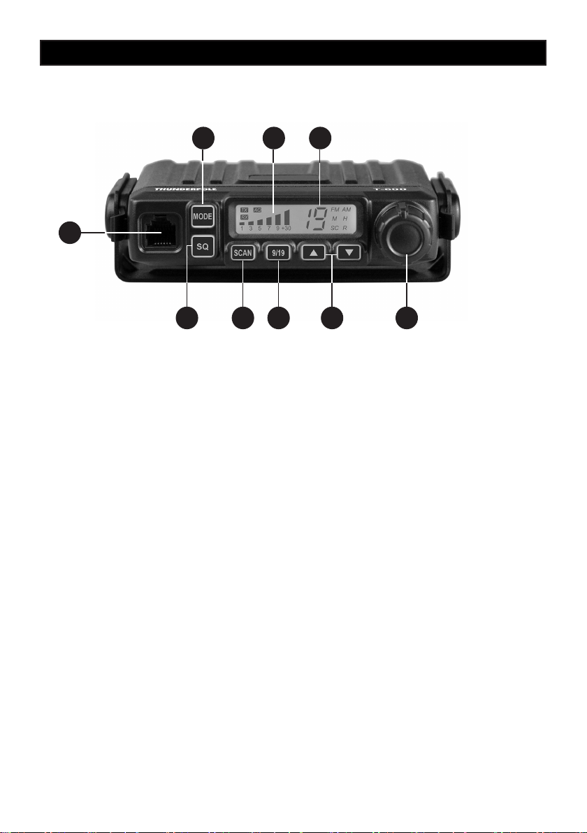
Front Panel
7 8 9
1
2 3 4 5 6
1. Microphone Connector
Connect the microphone to this connector and insert it until it clicks securely in.
2. SQ (Squelch) Button
A short press of this button allows you to change the squelch level using the Up / Down buttons (5) or
(14) and (16) on the microphone.
0. = Squelch off (hear all signals and noise)
0.1 = Lowest Squelch level (hear weak signals through to strong signals)
2.8 = Highest Squelch level (hear only the strongest signals)
A long press of this button will switch the ‘Auto Squelch’ function on (or off), this automatically silences
receiver noise, avoiding squelch manual adjustment, when switched on ‘AQ’ will be displayed on the
screen and there are 9 auto squelch levels to choose from. We suggest to start with A.1 and if you hear
noise move up a level, until you hear only silence or transmissions:
A.1 = Lowest Auto Squelch level (hear weak signals but also maybe noise)
A.9 = Highest Auto Squelch level (hear no noise but only the strongest signals)
3.Scan Button
A short press of this button will enter SCAN mode and the radio will scan until a transmission is found.
4. Channel 9 / 19 Button
A short press of this button will change the channel to 9, short press again for channel 19, then again to
go back to your chosen channel.
A long press of this button will enter LOCK mode and LC will be displayed on the screen temporarily, all
button presses will be invalid whilst in this mode. To exit LOCK mode long press the button again
- 2 -
Page 5
Controls and operation
5. Up / Down Buttons
These buttons change the channel up or down by 1 channel, you can also change the squelch level by rst
short pressing the SQ button.
6. On / Off / Volume Control
Use this knob to switch radio ON and OFF, as well as to adjust the receiver volume to the desired level.
7. Mode Button
A short press of this button whilst the radio is programmed to the UK frequency band will change the band
between UK (FM), EU (FM) and EU (AM) frequency bands. If the radio is programmed to a different band that
allows AM/FM operation, this button will just alternate between AM and FM mode.
A long press of this button will enter the band selection mode and the frequency band can be changed using
the Up and Down Buttons (5). To select a band long press again, or short press the PTT button.
A table of frequency bands can be found on page 6.
8. RX /TX Signal Meter
6-bar LED display to indicate the strength of the received signal, or the power of the outgoing signal.
9. CHANNEL DISPLAY
The display shows the channel number.
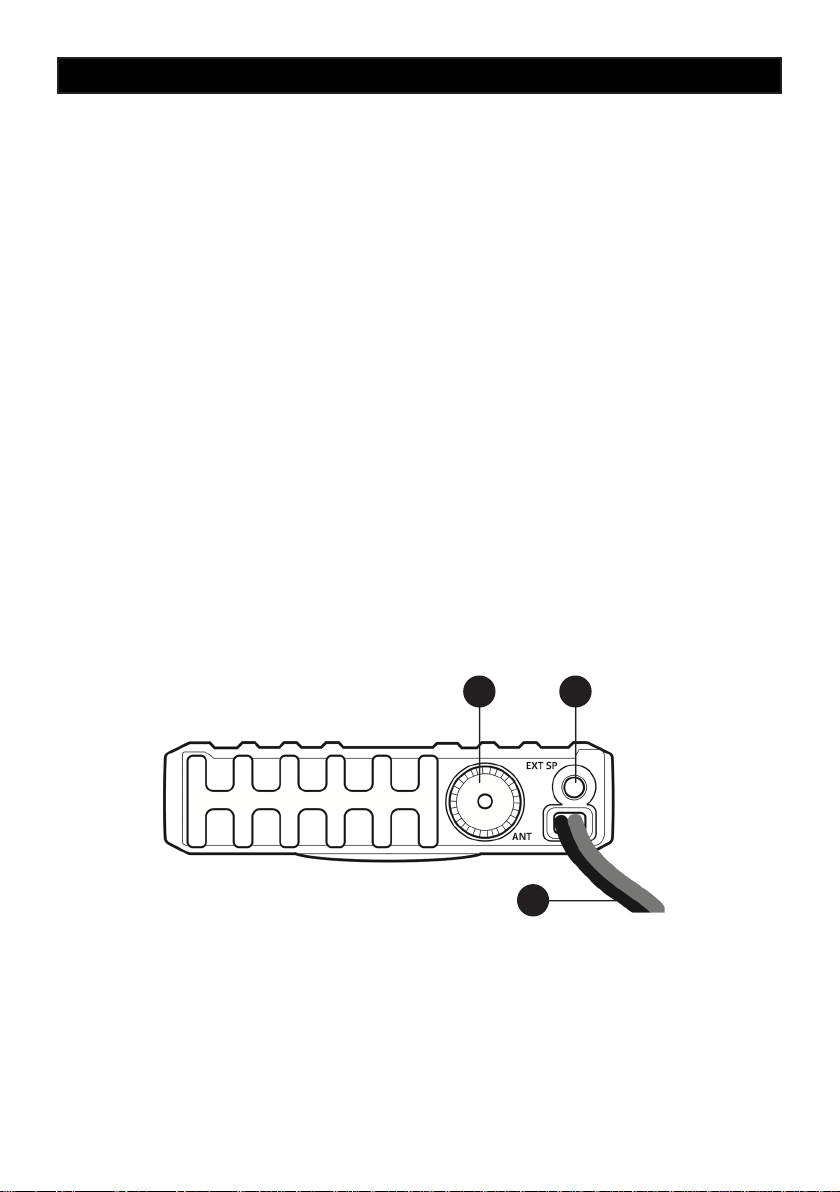
Rear Panel
1112
10
10. 13.8VDC POWER CORD
Power cord input that can be connected to a 13.8v supply in your vehicle or suitable DC power supply
unit.
11. EXT (External Speaker) Jack
This jack is for connecting an external speaker (optional).
12. ANTENNA Connector
Antenna connector. Refer to the section INSTALLATION OF THE ANTENNA (Page 5).
- 3 -
Page 6
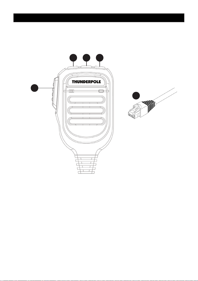
Microphone
13
Controls and operation
14 15 16
17
13. PTT (Push-to-Talk) Button
Transmitter button. Press the PTT button to transmit and release it to return to the receive mode.
14. Up Button
This button allows you to change the operating channel upwards (or the squelch level, see page 2.)
15. ASQ Button
This button has the same functionality as the SQ (2) button on the radio, see page 2 for more details.
16. Down Button
This button allows you to change the operating channel downwards (or the squelch level, see page 2.)
17. MICROPHONE Plug
RJ microphone connector. Connect it to the microphone connector (1) on the front panel of the radio.
- 4 -
Page 7

Installation
Installation
Before installing the main unit in the vehicle, check and select the most convenient location, in
order that the radio will be easy to reach and comfortable to operate, without obstructing any of the
vehicles controls. Use the supplied bracket and hardware to install the radio.
Installation of the Main Unit
Before connecting the radio to the vehicles electric system, make sure that radio is switched off,
with the OFF/VOLUME (6) knob completely turned counter clockwise at OFF position. The DC
power cable (10) of the radio is complete with a fuse holder with fuse located on the red positive (+)
wire. Connect the DC power cable to the vehicles electric system, with special attention to correct
polarity. Connect the red wire to the positive (+) pole and the black wire to the negative (-) pole of
the vehicles electric system. Make sure that the wires and terminals are rmly and stably connected, in order to prevent cables from disconnecting or causing short circuits.
Installation of the Antenna
A specic 27MHz CB antenna must be used. Please make sure to carefully install the antenna
mount on the vehicle with a good connection to ground. Before connecting the antenna to the radio,
it is necessary to check the correct operation of the antenna with low standing wave ratio (S.W.R.),
using an SWR meter. If not, the transmitter circuit of the radio could be damaged. The antenna
should be installed on the highest part of the vehicle, free from obstacles and as far away as possible from any source of electric or electromagnetic noise. The RF antenna coaxial cable must not
be damaged or pressed on its way between antenna and the radio. The correct operation of the
antenna and the low standing wave ratio (S.W.R.) must be checked periodically. Connect the RF
antenna coaxial cable to the antenna connector (12), located on the rear side of the radio.
Checking Operation of the Radio
Once the radio has been connected to the vehicles electric system and to the antenna, the correct
operation of the system may be checked. Please proceed as follows :
1) Check that the power cable is correctly connected.
2) Check that the RF antenna coaxial cable is correctly connected.
3) Connect the microphone to the connector (1), located on the front side of the radio.
4) Turn the radio on using the ON/OFF/VOL (6) knob and adjust the volume to the desired level.
5) Select the desired channel, using the channel selector buttons (5, or 14 and 16 on mic).
6) Set the SQUELCH level using SQ button (2), to cut the background noise.
7) Press the PTT (13) key to transmit and release it to receive.
- 5 -
Page 8
Frequency band selection / table
Frequency Band Selection / Programming
This Thunderpole T-600 CB radio must be programmed and exclusively used on a frequency band
allowed in the country where the product is used (see below). When radio is switched ON, the
current programmed frequency band code will be displayed for approx. 1 second. To program a
different frequency band, proceed as follows :
1) Long press the Mode button (7) until the frequency band ID is displayed on the screen
2) Use the Up / Down buttons (5) to choose the frequency band required (see table below)
3) To select the band long press the Mode button (7) again
UK/CE Channel Selection (Frequency Band “U”)
If the UK Frequency band has been selected, all 80 channels available for UK use can be accessed
by short pressing the ‘Mode’ button (7), this will change the band between UK(FM) , EU(FM) and
EU(AM) frequency bands. If the radio is programmed to a different band that allows AM/FM operation, this button will justalternate between AM and FM mode.
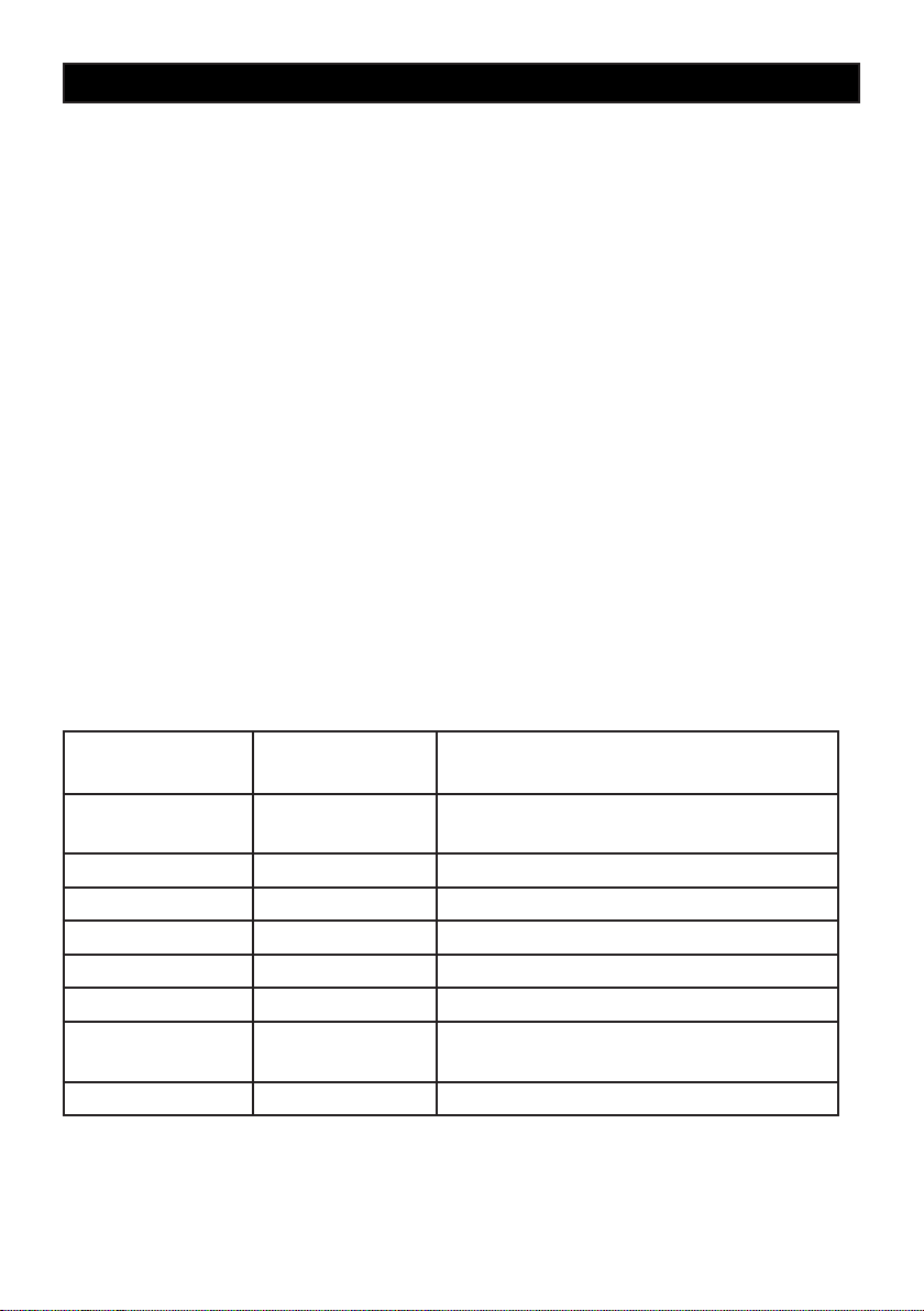
Frequency Band Table
7 programmable frequency bands are available, as per the below table :
FREQUENCY BAND
ID CODE
UK UK 40 FM UK CHANNELS
EU EUROPE 40CH FM 4W - 40CH AM 4W
CE EUROPE 40CH FM 4W
PL POLAND 40CH FM 4W - 40CH AM 4W
I ITALY 40CH FM 4W - 40CH AM 4W
I2 ITALY 34CH AM / FM 4W
DE GERMANY 40CH FM / AM 4W
IN EUROPE 27 CH AM / FM 4 W
COUNTRY SPECIFICATIONS
(Channels, Operating Modes, TX Power)
40 FM / AM EU CHANNELS
80CH FM 4W
- 6 -
Page 9
User information
Attention ! This radio has been pre-programmed on the UK frequency band (UK 40CH FM 4W) for
use in the UK only. For use in other countries, please refer to the frequency band table on page 6.
User Information
in accordance with art. 13 of the Legislative Decree of 25th July 2005, no. 15 ”Implementation of
Directives 2002/95/EC, 2002/96/EC and 2003/108/EC, relative to reduction of the use of hazardous
substances in electrical and electronic equipment, in addition to waste disposal”.
The crossed bin symbol shown on the equipment indicates that at the end of its
working life the product must be collected separately from other waste.
The user must therefore take the above equipment to the appropriate differentiated
collection centres for electronic and electro technical waste, or return it to the dealer
when purchasing a new appliance of equivalent type, in a ratio of one to one.
Appropriate differentiated waste collection for subsequent recycling, treatment and environmentfriendly disposal of the discarded equipment helps to prevent possible negative environmental and
health effects and encourages recycling of the component materials of the equipment.
Illegal disposal of the product by the user will be punished by application of the administrative nes
provided for by the legislative decree no. 22/1997 (article 50 and following of the legislative decree
no. 22/1997).
IMPORTANT !
Never attempt to open the cabinet of the transceiver. No user serviceable parts inside. Internal
modications or tampering may cause damage to the product, modifying its technical specications
will void all warranty rights.
If service or repair is required, please go to an authorised service centre or specialised technician.
- 7 -
Page 10

Specications
General
Channels 40 AM / FM (refer to the frequency bands table at page 6)
Frequency range 26.565 - 27.99125 MHz
Operating temperature -20°/+60°C
DC input voltage 13.8Vdc ±15%
Size 102 (W) x 27 (H) x 110 (D) mm
Weight 385 gr.
Receiver
Sensitivity better than 0.25uv@12db
Audio output 1W at 8 ohm
Image rejection 70dB
Adjacent channel 60dB
Frequency Response 300-3000Hz
Transmitter
Frequency error ±300Hz
Maximum RF power 4W at 13.8Vdc
Spurious transmissions < 4nW (-54 dBm)
Adjacent channel rejection 60dB
Modulation 80% to 90% (AM)
Deviation 1.7KHz - 2.0 KHz (FM)
Impedance 50 ohm unbalanced
Current drain 2A Max
- 8 -
Page 11
Notes
Page 12

 Loading...