

Page 1

8261 State Route 235
Dayton, OH 45424 USA
Phone: (937) 482-0200
Fax: (937) 482-0030
www.apache-laser.com
Operator’s Manual
Model 54 - Exterior
Model 56 - Interior
THUNDER® Laser Detector
Page 2

Thank you for purchasing an Apache Technologies, Inc.
product. Your THUNDER® Laser Detector is a premium
quality tool that has been designed and manufactured to
provide years of precise and reliable performance.
This manual is an important part of your purchase as it
will familiarize you with the unit and explain the numerous
features that have been designed into it. Please read this
manual thoroughly before using your THUNDER Laser
Detector.
Contents
THUNDER Laser Detectors
Models 54 and 56
General Description ...................................................2
Operation Model 54 ................................................... 3
Please contact your Apache dealer or the Apache factory
should you have questions regarding specific applications
or if you require additional information.
IMPORTANT: Fill out the Warranty Registration Card
and return it to Apache Technologies, Inc.
Please record your THUNDER Laser Detector information
below for future reference.
MODEL / SERIAL NO: ___________/___________
DATE OF PURCHASE: ______________________
PURCHASED FROM: _______________________
_______________________
PHONE: _______________________
Operation Model 56 ................................................... 7
Maintenance and Safety ............................................9
Specifications ..........................................................10
Warranty .................................................................. 12
P/N ATI-230048 Rev C
Page 3

General Description
The THUNDER family of hand-held laser detectors is
designed to receive and indicate reference elevation
information from rotating laser levels.
Model 54 is designed for general outdoor use. It has a
Liquid Crystal Display (LCD) on the front that gives a
visual indication of High, Low or On-grade. A beeper
also emits three distinct audible tones for High, Low or
On-grade. A general purpose rod clamp is included with
the Model 54.
Model 56 is designed for interior applications with visible
beam rotating lasers. It may also be used with exterior
invisible rotating lasers. It uses Light Emitting Diodes
(LED’s) on the front for grade indicators which display red
for high or low and green for on-grade. A beeper also emits
three distinct audible tones for each of the three grade
channels. A magnet is built into the top of the housing to
attach it to ceiling grids. A lanyard is included as a drop
protection device.
The THUNDER Detectors have been specifically designed
for use in harsh, loud construction environments. Impact
resistant housings, recessed windows, waterproof design,
attached battery doors, durable battery contacts, and a high
volume beeper are incorporated into every detector.
THUNDER Laser Detector
Model 54 - Exterior
3
1
2
1. Power Switch and Loudness Selector - turns the unit
on and off and selects volume level.
2. Beeper Output - emits distinct sound for High, Low, and
On-grade elevations.
3. Laser Reception Window - protects the photocells which
detect the laser signal.
4. LCD Window - visually indicates the detectors position
relative to the laser beam. Also indicates power on and
low battery warning.
4
2
3
Page 4
THUNDER Laser Detector
Model 54 - Exterior
THUNDER Laser Detector
Model 54 - Operation
5
6
7
8
9
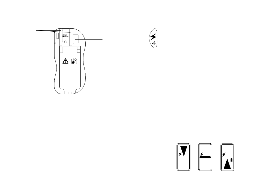
5. Clamp Slots - two dovetail slots accept the rod clamp.
6. Tab Slot - accepts clamp tab and locks clamp in place.
7. Offset Marking Notch - used for transferring reference
marks. The top of the detector is 1.0” (2.5 cm) above the
laser On-grade location.
8. Serial Number Label.
9. Battery Door - compression sealed battery compartment
houses 2 x “AA” batteries and ID label. Use a coin to open
the door latch and insert batteries noting the plus (+) and
minus (-) terminal diagram on the housing.
4
Press the power switch once to turn the detector
on. The beeper will sound and all the symbols on
the LCD will be visible. The power symbol will be
displayed to indicate the unit is on. Pressing and
releasing the power switch again will toggle through
volume selections of off, low, and high. Depressing and
holding the power switch for approximately 2 seconds will
turn the detector off. The unit will automatically shut off if
it is not used for 30 minutes.
The photocells that detect the laser beam are located
behind the reception window. This window must be directed
toward the laser to receive the beam.
When a beam is received, the LCD will visually indicate
the detector’s position relative to the laser beam. A low
battery warning symbol will appear when approximately
one hour of battery life remains.
LCD Grade Indication
Power
On
High On-grade Low
5
Low Bat-
tery
Indicator
Page 5
THUNDER Laser Detector
Model 54 - Operation
THUNDER Laser Detector
Model 56 - Interior
When a laser beam is received, the beeper will also emit
audible signals. Fast beeping means the detector is too
high, continuous is on-grade, and slow is too low.
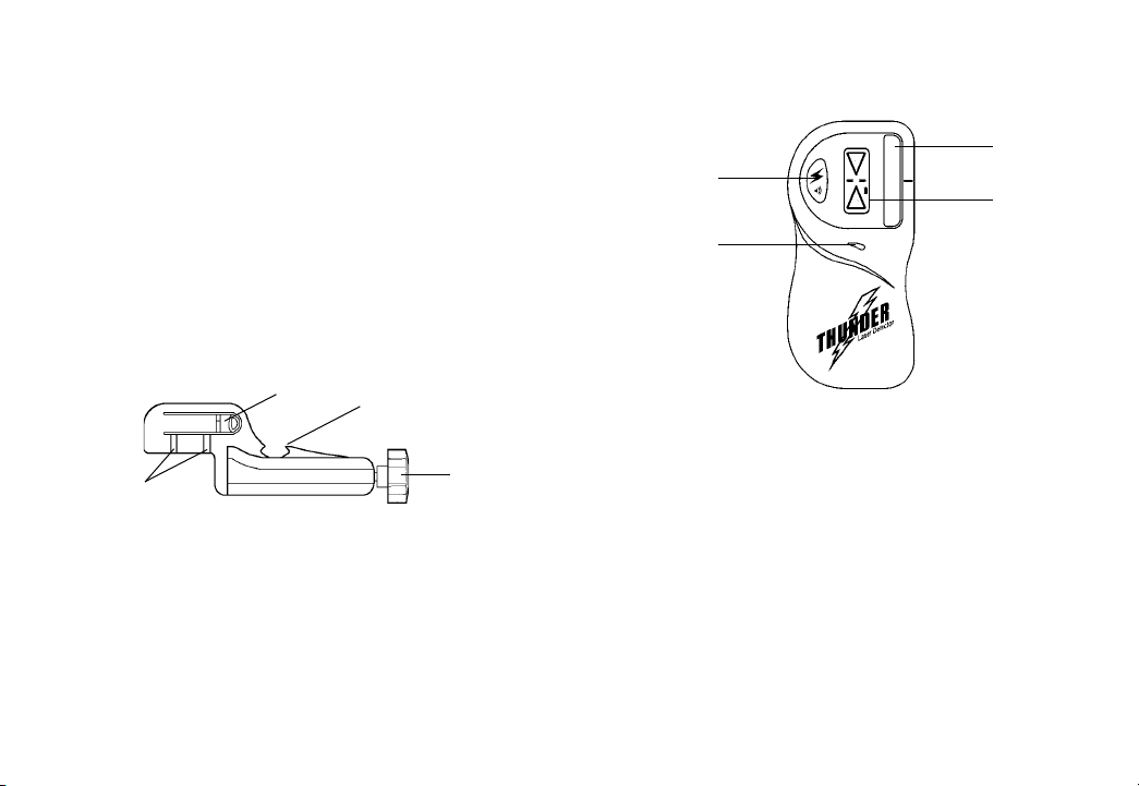
A Model 52 general purpose clamp is included with the
Model 54 to attach the detector to grade rods. To secure the
clamp to the detector, align the two dovetails of the clamp
to the grooves on the back of the detector. Slide the clamp
down onto the detector. A snapping action will ensure the
clamp is securely attached. To remove the clamp, depress
the thumb release tab and slide the clamp upward.
1
2
1. Clamp lock tab and thumb release - tab for securing and
thumb release for removing clamp from detector.
2. Dovetail slots - attaches clamp to the back of detector.
3. Reference Indicators - points are aligned with detector
On-grade for grade rod readings.
4. Clamping Screw - tightens the clamp onto rods and
staffs by moving the traveling jaw.
6 7
3
4
3
1
4
2
1. Power Switch and Loudness Selector - turns the unit
on and off and selects volume level.
2. Beeper Output - emits distinct sound for High, Low, and
On-grade elevations.
3. Laser Reception Window - protects the photocells which
detect the laser signal.
4. LED (Light Emitting Diode) Display - visually indicates
the detectors position relative to the laser beam. Also
indicates power on and low battery warning.
Page 6
THUNDER Laser Detector
Model 56 - Operation
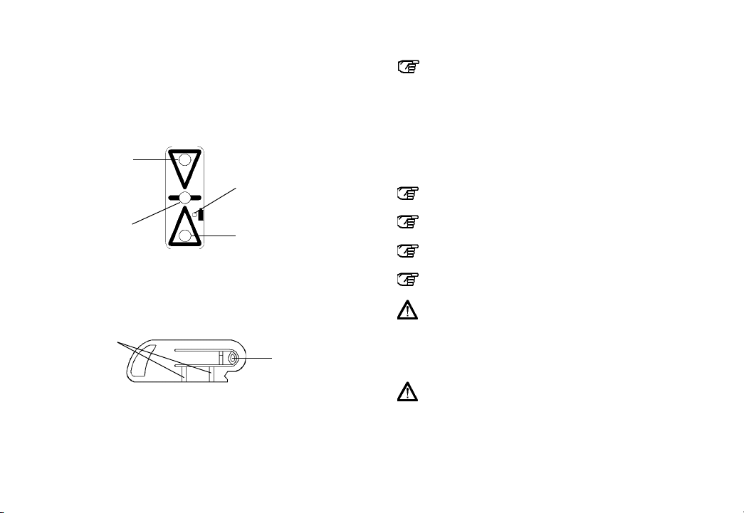
The operation of the Model 56 is similar to the Model 54
(Please refer to page 3). When a beam is received, the
LED will visually indicate the detector’s position relative
to the laser beam.
Red Light -
High Indication
Green Light -
On-grade
The center green LED will flash to indicate the detector is
on. The amber LED next to the battery symbol will appear
when approximately one hour of battery life remains.
Dovetail
Slots
A lanyard clip attaches to the detector in the same
manner as the Model 52 grade rod clamp. The lanyard
may be attached to the clip and used as a detector drop
protection device.
8
Amber Light -
Low Battery Indica-
tion
Red Light -
Low Indication
Thumb
Release
Maintenance and Safety
CLEANING: Do not wipe dust or dirt off the detector
reception window or display windows with a dry
cloth or other abrasive material as scratching could
occur, reducing visibility through these windows.
A soft cloth and mild soap and water are effective.
The unit may be submerged or sprayed with a low
pressure water hose if necessary. Do not use any
other fluids other than water or glass cleaner, as
they may attack polymer components.
TRANSPORT: Use the original carton or a laser
instrument case to transport the detector.
STORAGE: If the detector will not be used for a
month or more, remove the batteries.
BATTERIES: It is recommended to use only high
quality alkaline batteries.
INTENDED USES: The laser detector is designed
and suitable for detecting a rotating laser beam.
PROHIBITED USES:
- Operation without instruction.
- Operation other than the intended uses.
- Opening the detector, except the battery door.
- Modification or conversion of the detector.
- Use of accessories from other manufacturers.
PRECAUTIONS:
- The person in charge of the detector must understand the instructions in this manual and ensure
other users do also.
- Periodically carry out test measurements, particularly
after the detector has been subjected to abnormal use
and before and after important measurements.
9
Page 7

THUNDER Laser Detector
Model 54 - Exterior - Specifications
Detection Accuracy (Typical)
Model 54 ±0.080” (±2.0 mm)
Model 54-N ±0.030” (±0.75 mm)
Display LCD (arrow/bar/arrow)
Sealing Dustproof, Waterproof
Detection Range Up To 500 ft. radius
(dependent on laser) (150 m)
Mounting Conventional Clamp
Beeper Volumes High: 100+ dBA
@ 8 in. (20 cm) Low: 65 dBA
Display Channels 3
Window Capture Height 1.5 in. (38 mm)
Reception Angle ± 45°
Marking Notch 1.0 in. (25 mm)
Photocell side only
Low Battery Indicator Yes (LCD Symbol)
Battery Life 100+ hours continuous
Battery Size 2 x “AA”
Automatic Shut-Off 30 minutes
Operating Temperature -4°F to +140°F
(-20°C to +60°C)
*Specifications subject to change without notice
10
THUNDER Laser Detector
Model 56 - Interior - Specifications
Detection Accuracy (Typical) ±0.030” (±0.75 mm)
Display LED’s (red/green/red)
Sealing Dustproof, Waterproof
Detection Range Up To 300 ft. radius
(dependent on laser) (90 m)
Mounting Magnet Mount (top),
Lanyard
Beeper Volumes High: 100+ dBA
@ 8 in. (20 cm) Low: 65 dBA
Display Channels 3
Window Capture Height 1.5 in. (38 mm)
Reception Angle ± 45°
Marking Notch 1.0 in. (25 mm)
Photocell side only
Low Battery Indicator Yes (Amber LED)
Battery Life 75+ hours continuous
Battery Size 2 x “AA”
Automatic Shut-Off 30 minutes
Operating Temperature -4°F to +140°F
(-20°C to +60°C)
*Specifications subject to change without notice
11
Page 8

Warranty
Apache Technologies, Inc. THUNDER laser detectors are
warranted to be free of defects in material and workmanship
for a period of two years. This warranty period is twenty-four
months from the date the product is delivered from the
dealer to the purchaser or is put into service by a dealer
as a demonstration unit or rental unit.
A Warranty Registration Card must be filled out properly
and on file with Apache Technologies, Inc. or proof of
purchase presented to obtain warranty service.
Any evidence of misuse, alteration, or an attempt to
repair products by unauthorized personnel, or use of parts
other than those provided by Apache Technologies, Inc.
automatically voids the warranty. Competitor purchased
and tested units are excluded from this warranty.
The user of the product is expected to follow all operating,
maintenance and care instructions.
Apache Technologies, Inc. liability under this warranty is
limited to repairing or replacing any product returned to its
factory for that purpose. The foregoing states the entire
liability of Apache Technologies, Inc. regarding the purchase
and use of its product and they shall not be held responsible
for any consequential loss or damage of any kind.
This warranty is in lieu of all other warranties, expressed
or implied, and constitutes all of Apache Technologies, Inc.
liability with respect to merchandise sold by it.
12
CE DECLARATION OF CONFORMITY
Application of Council Directive:
89/336/EEC
Manufacturer's Name:
Apache Technologies, Inc.
Manufacturer's Address:
8261 State Route 235
Dayton, OH 45424 USA
European Representative Address:
Apache Technologies Europe GmbH
Langenberger Str. 590
D-45277 Essen, Germany
Model Number(s):
Thunder Model 54, 56
Equipment Type / Environment:
ITE / residential, commercial, light industrial
Harmonized Standards Applied:
Electromagnetic Compatibility (EMC),
EN 61000-6-1: 2001; EN 61000-4-2: 1995
EN 61000-4-3: 1995; EN 61000-4-8: 1995
EN 61000-6-3: 2001; EN 55011: 1998
We herewith declare, in exclusive responsibility, that the instrument conforms to the above mentioned directive including their amendments up to
the date below.
September 2003
Robert G. Conner, President
Notice to Our European Union Customers
For product recycling instructions and more information,
please go to: www.trimble.com/environment/summary.html
Recycling in Europe
To recycle Trimble WEEE, call: +31 497 53 2430,
and ask for the “WEEE associate,” or
mail a request for recycling instructions to:
Trimble Europe BV
c/o Menlo Worldwide Logistics
Meerheide 45
5521 DZ Eersel, NL
 Loading...