

Thundercomm Technology TURBOXSOMS820 User Manual
Quick Start Guide
6
9
10
11 13 14
16
24
25
26
28
29
30
8
12
3137
36
3539 34 3338
23
27
32
5
7
1
3
4
6
9
10
11 13 14
16
18
19
24
25
26
28
29
30
21
20
8
12
15
3137
40
36
3539 34 3338
22
23
27
32
5
2
17
7
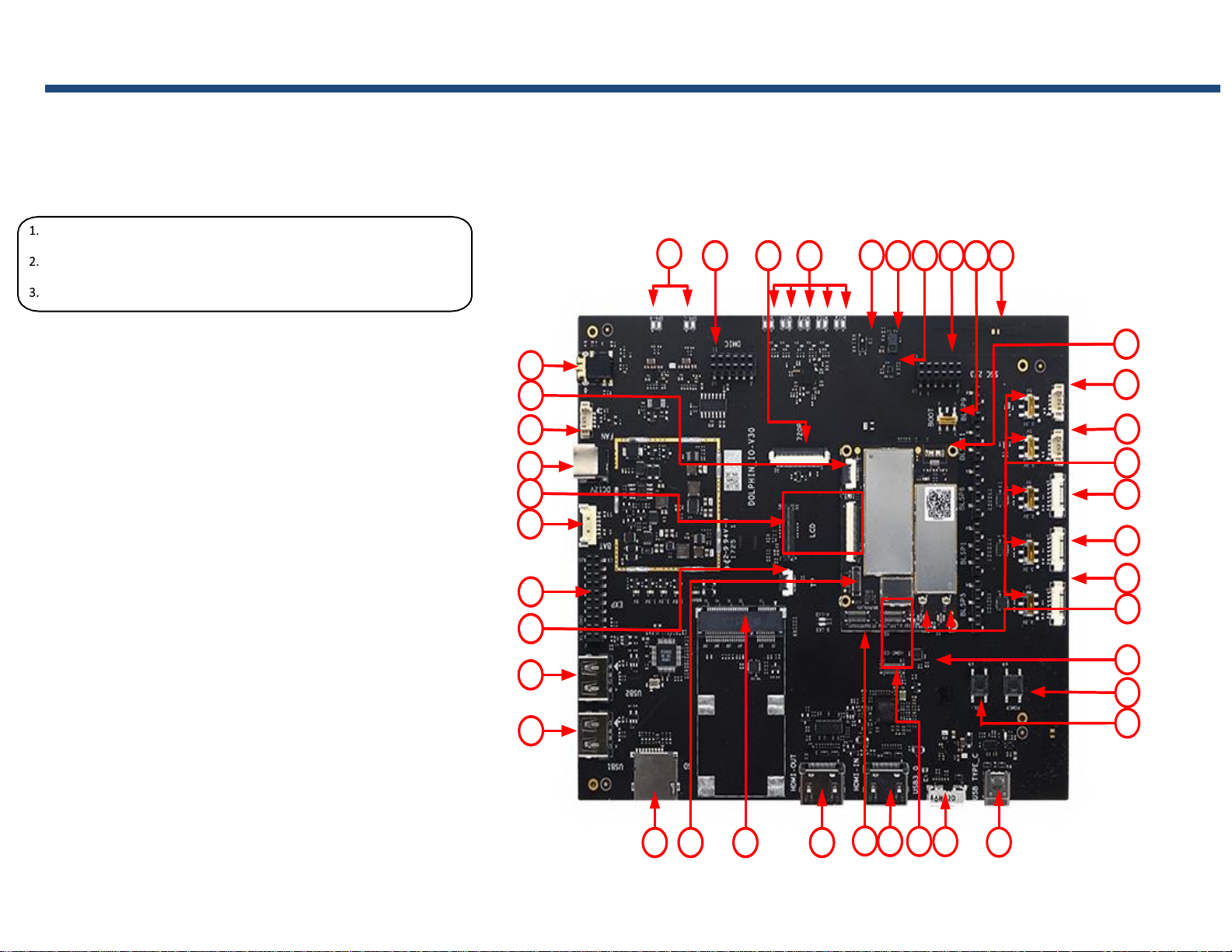
Package Contents
SOM Board with APQ8096 processor
Carrier Board
AC Power Adaptor
1. Headset Jack
2. Key connector
3. Fan connector
4. 12V DC Jack
5. LCM Convert connector
6. Battery connector
7. General purpose header
8. Touch Panel connector
9. USB 2.0 Type A connector 2
10. USB 2.0 Type A connector 1
11. TF Card
12. MIPI camera connector 0
13. Mini-PCIE connector
14. HDMI OUT connector
15. MIPI camera connector 1
16. HDMI IN connector
17. HDMI IN FPC connector
18. Micro USB3.0 connector
19. USB Type C connector(O)
20. VOL down or Reset button
21. Power button
22. A+G+M IMU
23. WLAN ext. ant. Connector
24. BLSP5 connector
25. BLSP1 connector
26. BLSP6 connector
27. Switch (5V/3.3V change)
28. UART11 connector
29. UART9 connector
30. Micro USB2.0 connector
31. Antenna 0 on board
32. Switch for Power on mode
33. Sensor Core I2C connector
34. MAG Sensor
35. Gesture Sensor
36. Proximity Sensor
37. Analog MICs
38. 720P LCD connector
39. DMICs connector
40. Speakers connector
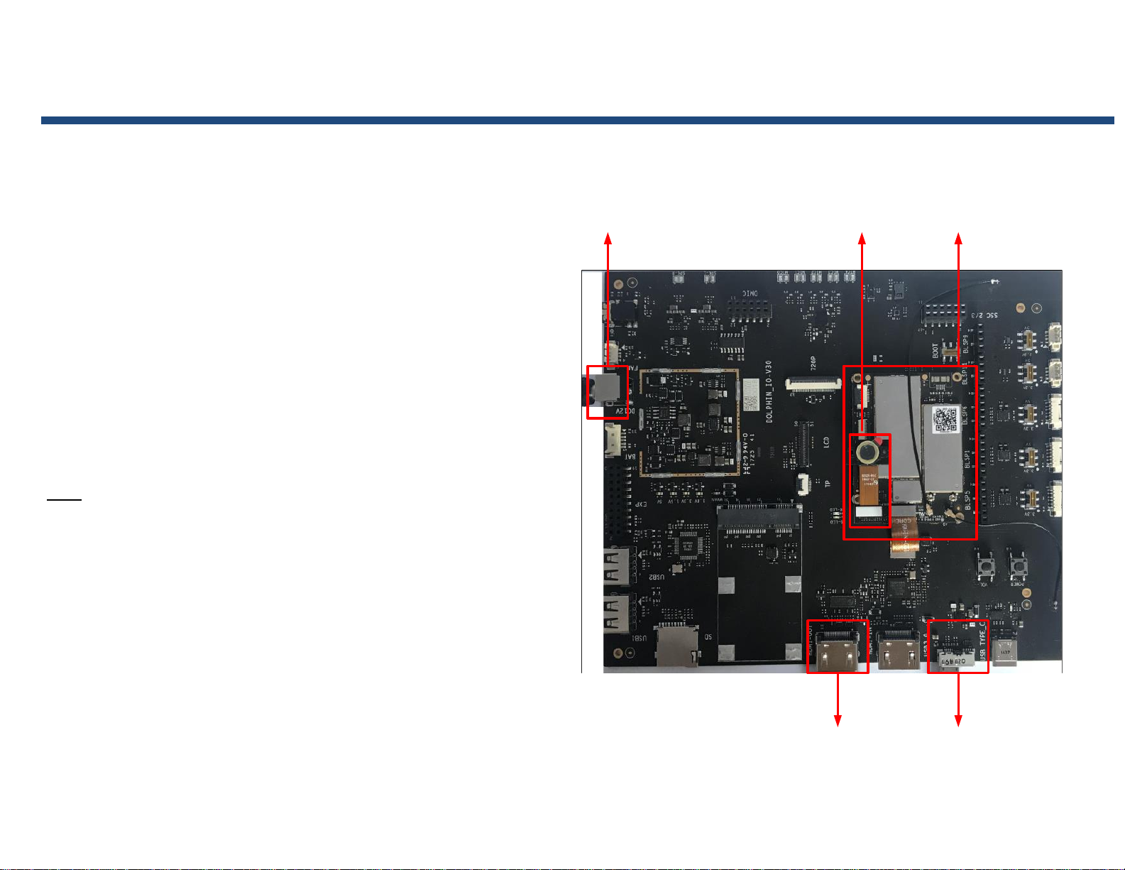
Quick Start Guide
SoM
IMX214
Camera
Power
Adapter
HDMI-OUT
USB 3.0
Thundersoft TurboX® S820 EVB Setup
Remove Thundersoft TurboX® S820 EVB board carefully from the anti-static bag
Connect SOM board, Carrier board and IMX214 Camera to the corresponding connector
as show below.
Connect Thundersoft TurboX® S820 EVB to a display through HDMI cable.
Connect Thundersoft TurboX® S820 EVB and PC through the USB cable.
Connect the Power Adapter to the Thundersoft TurboX® S820 EVB.
USB connector (18) as the debug interface, when need debugging.
Press power button (21) for 2 seconds the board will boot automatically.
Notes:
All FPC with ‘TEXT’ mark.
‘MB’ connecting to the SOM Board.
‘IO’ connecting to the Carrier Board.
Keep the ‘TEXT’ side up.
 Loading...