

Thundercomm Technology TURBOXSOMD845 User Manual

Thundercomm TurboX D845 System on Module
Thundercomm TurboX
A high performance embedded platform based on Qualcomm® Snapdragon
TM
D845 System on Module
845
™
processor
Description
Thundercomm TurboXTMD845 System on Module(SOM) is a high performance intelligent module, integrating
Android or Linux system, based on Qualcomm SDA845 processor. It integrates the advanced 10 nm Fin FET
process, a customized 64-bit ARM v8-compliant Octacore Qualcomm Kryo 385 applications processor.
TurboX D845 SOM supports short-range wireless communication through Wi-Fi 802.11 a/b/g/n/ac and BT5.0.
This SOM supports 3840*2400@60fps display, it can connect 4 x camera modules, and integrating multiple
audio and video input/output interfaces. This SOM provides a variety of GPIO, I2C, UART and SPI standard
interfaces. In addition, it supports two MIPI-DSI, four MIPI-CSI and SOM common standard protocol
interfaces such as USB3.1, PCIE2.1/3.0, I2S and SLIMBUS.
TurboX D845 SOM provides convenient and stable system solution for IOT field, it can be embedded into the
device on VR/AR, Drone, Robot, Smart Camera, AI devices, and any other connecting fields. The size of
module is 37mm x 60mm x 7.1mm, weight 10.3g, with 336PINs.
Features
The following table shows the detailed features and performance on TurboX D845 SOM.
Processors
64-bit applications processor (Kryo 385) with 2 MB L3 cache
Applications
Processor
Quad high-performance Kryo cores at 2.649 GHz - Kryo Gold cluster with 256 kB L2
cache per core
Quad low-power Kryo cores at 1.766 GHz - Kyro Silver cluster with 128 kB L2 cache
per core
Digital signal
Compute DSP with Qualcomm Hexagon Vector Extensions (dual-HVX512) processor
processing
Copyright © 2018 All Rights Reserved , Thundercomm Technology Co., Ltd.
1

Thundercomm TurboX D845 System on Module
Sensor core
Operating System Android OS 8
Memory
Snapdragon™ sensor core with dedicated sensor DSP and 1.0 MB memory (512 kB
TCM + 512 kB L2) to support always-on low-power use cases
64GB UFS + LPDDR4x 4GB
Four-channel PoP high-speed memory – LPDDR4x SDRAM (4 x 16-bit) designed for a
1866 MHz clock.
Multimedia
2 x 4-lane DSI DPHY 1.2 and DisplayPort 1.4 data concurrency over USB
Maximum concurrency configurations
Display support
3840x2400 at 60Hz primary + 3840 x 2160 or 4096 x 2160 at 60Hz DP
2 x 2560 x 1600 at 60 fps primary + 3840 x 2160 or 4096 x 2160 at 60fps DP
Support 3 x 4-lane MIPI_CSI + 1 x 2-lane MIPI_CSI
Dual 14-bit ISP + one Lite ISP
Camera support
Real-time sensor input resolution: 16 + 16 +2 MP
32 MP 30 fps ZSL with a dual ISP
16 MP 30 ZSL with single ISP
Video
4K60 encode for H.264 High Profile, H265 Main 10 Profile
Encode
4K30 encode for VP8
Decode 4K60 decode for H.264 High Profile, H265 Main 10 Profile and VP9 Profile 2
Graphics Adreno 630 - 4K 60 fps UI or 2x 2k x 2k 90 fps UI
Copyright © 2018 All Rights Reserved , Thundercomm Technology Co., Ltd.
2

Thundercomm TurboX D845 System on Module
OpenGL ES 3.2 + AEP, DX next, Vulkan 2
OpenCL 2.0 full profile, RenderScript
Audio (build in TurboX D845 Carrier Board)
Five DACs, five outputs
five differential analog inputs; four ADCs
Six digital microphones
Codec
Open DSP CPE voice activation subsystem for ultra low-power voice wake-up
Native DSD (WCD9341 only), MBHC, and ANC
130 dB dynamic range, 32-bit DAC
Low-power audio
Voice codec
support
Enhanced audio
Low-power, low-complexity; 7.1 surround sound
QCELP, EVS, EVRC, EVRC-B, EVRC-WB; G.7 Gen, G.729A/AB;
GSM-FR, GSM-EFR and GSM-HR; AMR-NB and AMR-WB
Surround sound: advanced multichannel
FluenceTMPro noise cancellation; enhanced speaker protection
Qualcomm enhance 3D audio solution, Qualcomm stereo audio expansion feature,
and Qualcomm intelligent mixing algorithm
Wireless connectivity
2.4G/5G, support 802.11 a/b/g/n/ac, 2 X 2 MIMO
WLAN
Support Bluetooth 5.0 + HS
Bluetooth
BLE
Connectivity
Copyright © 2018 All Rights Reserved , Thundercomm Technology Co., Ltd.
3

Thundercomm TurboX D845 System on Module
USB
PCIe 2x PCIe, one Gen 2 1-lane with PHY 2.1 and one Gen 3 1-lane with PHY 3.0
SDIO SD V3.0 4-bit for SD card
QUP 4 bit each; Multiplexed serial interface functions, can be configured as UART, I2C, SPI
SLIMbus One, highly multiplexed, high-speed, baseline WCD9340/WCD9341
MI2S
GPIO
2x USB 3.1, one can support Type-C with DisplayPort
Full duplex stereo or up to quad channel Tx/Rx MI2S (x3)
Up to eight channels for multi-channel Tx/Rx audio applications (x1)
12+ GPIO ports
Others
Support ADC interfaces
ADC Interface
Touchscreen
support
Physical size
Operating
temperature
RoHS All hardware components are fully compliant with EU RoHS directive
used for input voltage sense, battery temperature detection and general purpose
ADC
Capacitive panels via ext IC (I2C, and interrupts)
Size: 37mm x 60mm x7.1mm
Weight: approx. 10.3g
Interface: Connector
-20~50℃
Copyright © 2018 All Rights Reserved , Thundercomm Technology Co., Ltd.
4
Thundercomm TurboX D845 System on Module
Applications
TurboX D845 SOM is ideal for many applications including (but not limited to): AI, Robotics, Virtual Reality
(VR), Augmented Reality (AR),Drones and Medical Devices.
Revision History:
Version Date Description
V1.0 July 31, 2018 Revised Release
V1.1 Sep 28, 2018 Update the pin definition description
V1.2 Oct 8, 2018 Update format
Copyright © 2018 All Rights Reserved , Thundercomm Technology Co., Ltd.
5

Thundercomm TurboX D845 System on Module
Table of Contents
1 Physical Description............................................................................................................................................ 9
1.1 Major Components Location................................................................................................................9
1.2 Connectors Function and Part Number................................................................................................ 10
1.3 Package Drawing and Dimensions.......................................................................................................11
2 Functional Overview..........................................................................................................................................12
2.1 DSP(Hexagon v65)...............................................................................................................................12
2.2 Visual Processing Subsystem...............................................................................................................12
2.3 Secure Processing Unit (SPU)..............................................................................................................13
2.4 ISP(ISP280).......................................................................................................................................... 14
2.5 Connection............................................................................................................................................14
3 Interfaces Description........................................................................................................................................15
3.1 Interfaces Parameter Definitions..........................................................................................................15
3.2 Interfaces Detail Description................................................................................................................16
3.2.1 Power Supply Interface................................................................................................................ 16
3.2.2 Touchscreen Interface...................................................................................................................17
3.2.3 Display Interface.......................................................................................................................... 17
3.2.4 Camera Interfaces.........................................................................................................................18
3.2.5 Audio Interface.............................................................................................................................20
3.2.6 USB & DisplayPort Interface.......................................................................................................21
3.2.7 PCIe Interface...............................................................................................................................22
3.2.8 SSC Interface................................................................................................................................23
3.2.9 SDIO Interface..............................................................................................................................24
3.2.10 QUP Interface............................................................................................................................... 24
3.2.11 Power on Interface........................................................................................................................25
3.2.12 Reset Interface.............................................................................................................................. 26
Copyright © 2018 All Rights Reserved , Thundercomm Technology Co., Ltd.
6

Thundercomm TurboX D845 System on Module
3.2.13 Keys Interface...............................................................................................................................27
3.2.14 Sensor Interrupt Interface.............................................................................................................27
3.2.15 Debug UART Interface.................................................................................................................27
3.2.16 Battery Interface...........................................................................................................................28
3.2.17 ADCs Interface.............................................................................................................................28
3.2.18 PWMs and LED Current Driver Interface................................................................................... 28
3.2.19 Antenna Interface......................................................................................................................... 29
4 Connector PIN Summary......................................................................................................................................30
4.1 CON2401 BTB Connector................................................................................................................... 30
4.2 CON2402 BTB Connector................................................................................................................... 33
4.3 J2 BTB Connector................................................................................................................................ 36
5 Electrical Characteristics.................................................................................................................................. 37
5.1 Absolute Maximum Ratings.................................................................................................................37
5.2 Operating Conditions............................................................................................................................37
5.3 Digital-logic characteristics..................................................................................................................38
5.3.1 Digital GPIO characteristics.....................................................................................................38
5.3.2 SD card digital I/O characteristics............................................................................................... 39
5.4 MIPI......................................................................................................................................................40
5.5 USB.......................................................................................................................................................40
5.6 PCIe...................................................................................................................................................... 40
5.7 DisplayPort........................................................................................................................................... 41
5.8 SLIMbus............................................................................................................................................... 41
5.9 SDIO.....................................................................................................................................................41
5.10 I2S.........................................................................................................................................................41
5.11 I2C........................................................................................................................................................ 43
5.12 SPI.........................................................................................................................................................43
5.13 Fuel gauge.............................................................................................................................................44
Copyright © 2018 All Rights Reserved , Thundercomm Technology Co., Ltd.
7

Thundercomm TurboX D845 System on Module
5.14 LED Current Driver..............................................................................................................................44
5.15 ADC......................................................................................................................................................45
5.16 Power Consumption............................................................................................................................. 46
5.17 Thermal.................................................................................................................................................46
Copyright © 2018 All Rights Reserved , Thundercomm Technology Co., Ltd.
8
Thundercomm TurboX D845 System on Module
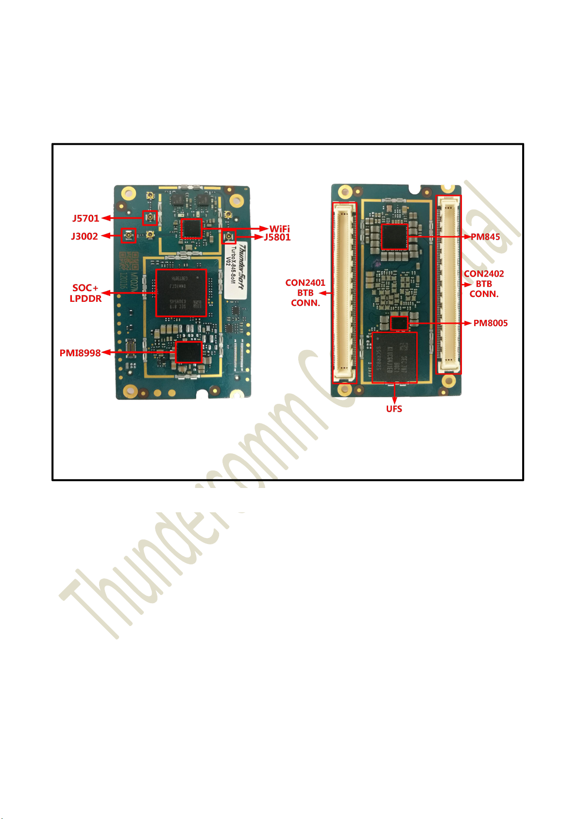
1.1 Major Components Location
1 Physical Description
TurboX D845 SOM’s major components as below map.
Figure 1.1- 1 TurboX D845 SOM Key component Location
Copyright © 2018 All Rights Reserved , Thundercomm Technology Co., Ltd.
9
Thundercomm TurboX D845 System on Module
1.2 Connectors Function and Part Number
Below table indicates connectors detail information.
Part Reference Description
BTB connectors, used for connecting to
CON2401,CON2402
Carrier Board.
J2 JTAG connector, used for JTAG Debug AXG7160J7 Panasonic
J3002,J5701,J5801 RF antenna connector, J3002 is for 818000500 ECT
Table 1.2- 1 Connector part number and information
Manufacturer Part
Manufacturer
Number
FX10A-168P-SV HIROSE
Copyright © 2018 All Rights Reserved , Thundercomm Technology Co., Ltd.
10
Thundercomm TurboX D845 System on Module
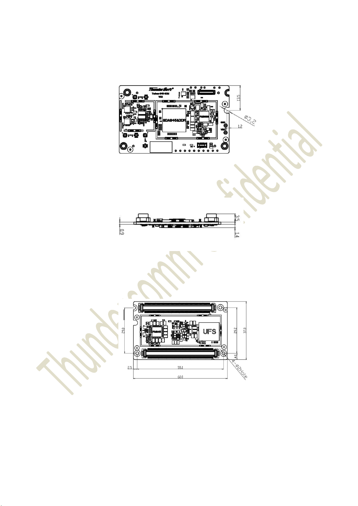
1.3 Package Drawing and Dimensions
Figure 1.3- 1 Top View
Figure 1.3- 2 Side View
Figure 1.3- 3 Bottom View
Copyright © 2018 All Rights Reserved , Thundercomm Technology Co., Ltd.
11

Thundercomm TurboX D845 System on Module
2 Functional Overview
2.1 DSP(Hexagon v65)
Hexagon Coprocessor (HCP) and VMA1.0
Universal Bandwidth Compression(UBWC) and DMA1.0
Vector TCM (VTCM)
Scatter-Gather support
HVX contexts and concurrency
Migrating to 128-byte mode for future forward compatibility
dspCV_init is deprecated
New HAP DCVS v2 APIs for clock and bus voting
dspCV_concurrency is deprecated
Session restart
SDK 3.x
Camera streaming – four tap points
Dedicated bus for camera streaming on the cDSP
Dedicated high-speed bus for data transfer from the DDR to the cDSP
FastCV software development kit with HVX acceleration
2.2 Visual Processing Subsystem
Improved GPGPU
Enhanced image processing for GPGPU use cases
Native MIPI and Bayer texture format support
Enhanced mathematics for machine learning (matrix Mul)
Architectural improvements for performance and power
Efficient multiview rendering for VR/AR
Copyright © 2018 All Rights Reserved , Thundercomm Technology Co., Ltd.
12

Thundercomm TurboX D845 System on Module
More efficient, wider Shader microarchitecture
Significant resource (ALU) increase in Shader Processors
Increased texture performance
Memory bandwidth reduction and efficiency improvements
Improved UI with updated 2D rasterization patterns
Improved hidden surface removal to reduce work
Better lossless compression to reduce memory bandwidth and power
Improvements for Vulkan support
Reduced overhead in hardware and driver
2.3 Secure Processing Unit (SPU)
Qualcomm Trusted Execution Environment
Isolates secure and non-secure software operations
Small code base, rigorously reviewed
Based on ARM’s TrustZone architecture
Secure Boot
Deters unauthorized code execution
Tamper resistant root of trust in ROM or e-fuses
Hardware Crypto
FIPS certifiable cryptographic engines and HW keys for more robust and fast encrypt/decrypt
Secure Storage and Key Provisioning
OTP e-fuse memory for storage of keys and configurations
Secure file system for encrypted storage of DRM keys and certificates
Provisioning of Keys
Secure Debug
Prevents JTAG debugger connection in commercial products and reverse engineering
Set by e-fuse, with support for secure RMA
operations
Copyright © 2018 All Rights Reserved , Thundercomm Technology Co., Ltd.
13

Thundercomm TurboX D845 System on Module
2.4 ISP(ISP280)
IFE: Image front-end engine
Bayer process for preview/video only
Stats for 3A
Muti-pass outputs feeding to IPE
IPE: Image processing engine, consists of 2 parts
NPS: Noise processing segment
PPS: Post processing segment
BPS: Bayer processing segment
Bayer process and noise reduction for snapshot only
Simple stats for special offline processing
Muti-pass outputs feeding to IPE
2.5 Connection
2 x 2 802.11ac with MU-MIMO
160 MHz & DBS support
Bluetooth 5.0
Optional dedicated BT antenna support concurrent operation for WLAN and BT with and without
RF performance meets all carrier requirments
Industry leading throughput
Low power island on MSM for lowest Wi-Fi power consumption (up to 61% improvement)
BT/BTLE integration within WCN3990 for lowest BT power consumption (up to 87% improvement)
dedicated BT antenna
Copyright © 2018 All Rights Reserved , Thundercomm Technology Co., Ltd.
14

Thundercomm TurboX D845 System on Module
3 Interfaces Description
3.1 Interfaces Parameter Definitions
This chapter introduces all the interfaces definition, purpose to guide developer easy to design and
verification on Thundercomm TurboXTMD845 SOM.
Symbol Description
AI Analog input
AO Analog output
B Bidirectional digital with CMOS input
CSI Supply voltage for MIPI_CSI circuits and I/O; (1.8 V only)
DI Digital input(CMOS)
DSI Supply voltage for MIPI_DSI I/O; (1.8 V only)
DO Digital output(CMOS)
H High-voltage tolerant
Programmable pull resistor. The default pull direction is indicated using capital letters
and is a prefix to other programmable options:
NP: pdpukp = default no-pull with programmable options following the colon (:)
nppdpukp
KP Contains an internal weak keeper device (keepers cannot drive external buses)
MIPI Mobile industry processor interface
PD: nppukp = default pull-down with programmable options following the colon (:)
PU: nppdkp = default pull-up with programmable options following the colon (:)
KP: nppdpu = default keeper with programmable options following the colon (:)
NP Contains no internal pull
OD Open drain
PD Contains an internal pull-down device
PI Power input
PO Power output
Copyright © 2018 All Rights Reserved , Thundercomm Technology Co., Ltd.
15
 Loading...